user's manual - Ana-Digi Systems
user's manual - Ana-Digi Systems
user's manual - Ana-Digi Systems

You also want an ePaper? Increase the reach of your titles
YUMPU automatically turns print PDFs into web optimized ePapers that Google loves.
CHAPTER 3 GENERAL SPECIFICATION<br />
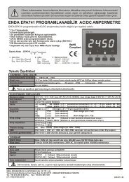
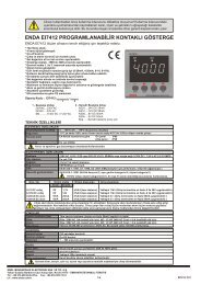
3.2 Pnet I/F Module Configuration<br />
G3L-PUEA<br />
RUN<br />
READY<br />
ERROR<br />
STATUS<br />
LINK-IF<br />
1<br />
G4L-PUEA<br />
RUN<br />
READY<br />
ERROR<br />
STATUS<br />
LINK-IF<br />
1<br />
G6L-PUEA<br />
RUN<br />
READY<br />
ERROR<br />
STATUS LINK<br />
COMM.<br />
CONN.<br />
1<br />
2<br />
G7L-PBEA<br />
PROGRAMMABLE<br />
LOGIC<br />
CONTROLLER<br />
COM RUN<br />
ERROR LINK-IF<br />
5<br />
1<br />
COMM.<br />
CONN.<br />
2<br />
CONFIG.<br />
CONN.<br />
3<br />
2 4<br />
COMM.<br />
CONN.<br />
2<br />
CONFIG.<br />
CONN.<br />
3<br />
CONFIG.<br />
CONN.<br />
3<br />
No. Names Description<br />
1 LED indicator Refer to LED display contents.<br />
2<br />
3<br />
Profibus-DP<br />
connector<br />
Configuration<br />
connector<br />
Connector for Profibus network (D-SUB 9 pin connector, female type)<br />
Connector to download the layout diagram of the prepared Profibus network, by<br />
using configuration tool.(D-SUB 9 pin connector, female type, refer to cable<br />
connection drawing.)<br />
4 Station no. switch Station no. switch of slave module (1~126 stations setting)<br />
5 Extension connector Connector to connect the extension module.<br />
Table 3.2 Module Configurations<br />
*G3L-PUEB, G4L-PUEB, G6L-PUEB are the same configuration.<br />
3-2