

SMX Programming Manual for the SMX Module - OEM Automatic AB
SMX Programming Manual for the SMX Module - OEM Automatic AB
SMX Programming Manual for the SMX Module - OEM Automatic AB

Create successful ePaper yourself
Turn your PDF publications into a flip-book with our unique Google optimized e-Paper software.
Logic Diagram<br />
SafePLC saves <strong>the</strong> configuration, <strong>the</strong> program sequence and <strong>the</strong> chosen<br />
parameterization as a Windows documents with <strong>the</strong> file name extension "*.plc<strong>SMX</strong>".<br />
The logic diagram is subdivided into field, which can take up <strong>the</strong> function blocks. The<br />
function blocks are inserted and displaced within this raster. Overlapping of function<br />
blocks is not possible.<br />
Within <strong>the</strong> logic diagram <strong>the</strong> two views "terminal diagram" and "logic diagram" are<br />
available <strong>for</strong> <strong>the</strong> user.<br />
The programmer is able to toggle between <strong>the</strong>se views as desired:<br />
Menu: View -> Change layout<br />
Keyboard: Crtl + Tab<br />
Control button in <strong>the</strong> toolbar "Drawing Aids"<br />
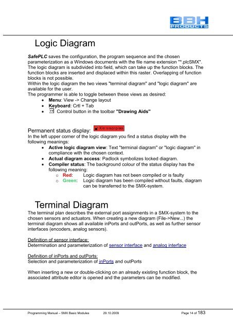
Permanent status display:<br />
In <strong>the</strong> left upper corner of <strong>the</strong> logic diagram you find a status display with <strong>the</strong><br />
following meanings:<br />
Active logic diagram view: Text "terminal diagram" or "logic diagram" in<br />
compliance with <strong>the</strong> chosen context.<br />
Actual diagram access: Padlock symbolizes locked diagram.<br />
Compiler status: The background colour of <strong>the</strong> status display has <strong>the</strong><br />
following meaning:<br />
o Red: Logic diagram has not been compiled or is faulty<br />
o Green: Logic diagram has been compiled without faults, diagram<br />
can be transferred to <strong>the</strong> <strong>SMX</strong>-system.<br />
Terminal Diagram<br />
The terminal plan describes <strong>the</strong> external port assignments in a <strong>SMX</strong>-system to <strong>the</strong><br />
chosen sensors and actuators. When creating a new diagram (File->New...) <strong>the</strong><br />
terminal diagram shows all available inPorts and outPorts, as well as fur<strong>the</strong>r sensor<br />
interfaces (encoders, analog sensors).<br />
Definition of sensor interface:<br />
Determination and parameterization of sensor interface and analog interface<br />
Definition of inPorts and outPorts:<br />
Selection and parameterization of inPorts and outPorts<br />
When inserting a new or double-clicking on an already existing function block, <strong>the</strong><br />
associated attribute editor is opened and <strong>the</strong> parameters can be modified.<br />
<strong>Programming</strong> <strong>Manual</strong> – <strong>SMX</strong> Basic <strong>Module</strong>s 29.10.2009 Page 14 of 183


