SMX Programming Manual for the SMX Module - OEM Automatic AB
SMX Programming Manual for the SMX Module - OEM Automatic AB
SMX Programming Manual for the SMX Module - OEM Automatic AB
Create successful ePaper yourself
Turn your PDF publications into a flip-book with our unique Google optimized e-Paper software.
Preparing <strong>the</strong> Wiring<br />
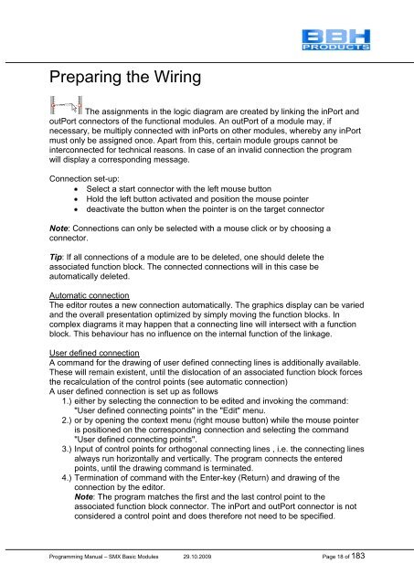
The assignments in <strong>the</strong> logic diagram are created by linking <strong>the</strong> inPort and<br />
outPort connectors of <strong>the</strong> functional modules. An outPort of a module may, if<br />
necessary, be multiply connected with inPorts on o<strong>the</strong>r modules, whereby any inPort<br />
must only be assigned once. Apart from this, certain module groups cannot be<br />
interconnected <strong>for</strong> technical reasons. In case of an invalid connection <strong>the</strong> program<br />
will display a corresponding message.<br />
Connection set-up:<br />
Select a start connector with <strong>the</strong> left mouse button<br />
Hold <strong>the</strong> left button activated and position <strong>the</strong> mouse pointer<br />
deactivate <strong>the</strong> button when <strong>the</strong> pointer is on <strong>the</strong> target connector<br />
Note: Connections can only be selected with a mouse click or by choosing a<br />
connector.<br />
Tip: If all connections of a module are to be deleted, one should delete <strong>the</strong><br />
associated function block. The connected connections will in this case be<br />
automatically deleted.<br />
<strong>Automatic</strong> connection<br />
The editor routes a new connection automatically. The graphics display can be varied<br />
and <strong>the</strong> overall presentation optimized by simply moving <strong>the</strong> function blocks. In<br />
complex diagrams it may happen that a connecting line will intersect with a function<br />
block. This behaviour has no influence on <strong>the</strong> internal function of <strong>the</strong> linkage.<br />
User defined connection<br />
A command <strong>for</strong> <strong>the</strong> drawing of user defined connecting lines is additionally available.<br />
These will remain existent, until <strong>the</strong> dislocation of an associated function block <strong>for</strong>ces<br />
<strong>the</strong> recalculation of <strong>the</strong> control points (see automatic connection)<br />
A user defined connection is set up as follows<br />
1.) ei<strong>the</strong>r by selecting <strong>the</strong> connection to be edited and invoking <strong>the</strong> command:<br />
"User defined connecting points" in <strong>the</strong> "Edit" menu.<br />
2.) or by opening <strong>the</strong> context menu (right mouse button) while <strong>the</strong> mouse pointer<br />
is positioned on <strong>the</strong> corresponding connection and selecting <strong>the</strong> command<br />
"User defined connecting points".<br />
3.) Input of control points <strong>for</strong> orthogonal connecting lines , i.e. <strong>the</strong> connecting lines<br />
always run horizontally and vertically. The program connects <strong>the</strong> entered<br />
points, until <strong>the</strong> drawing command is terminated.<br />
4.) Termination of command with <strong>the</strong> Enter-key (Return) and drawing of <strong>the</strong><br />
connection by <strong>the</strong> editor.<br />
Note: The program matches <strong>the</strong> first and <strong>the</strong> last control point to <strong>the</strong><br />
associated function block connector. The inPort and outPort connector is not<br />
considered a control point and does <strong>the</strong>re<strong>for</strong>e not need to be specified.<br />
<strong>Programming</strong> <strong>Manual</strong> – <strong>SMX</strong> Basic <strong>Module</strong>s 29.10.2009 Page 18 of 183


