Design Guide - Solvay Plastics
Design Guide - Solvay Plastics
Design Guide - Solvay Plastics

You also want an ePaper? Increase the reach of your titles
YUMPU automatically turns print PDFs into web optimized ePapers that Google loves.
Mechanical Properties<br />
The mechanical properties of a material are of<br />
fundamental importance to engineers when designing<br />
a part. The designer must match the mechanical<br />
properties of various candidate materials to the<br />
performance requirements of each application in order<br />
to determine which material is suitable for a given part<br />
design. Conversely, the designer can use the material<br />
property values to achieve an optimum part design.<br />
To assist the designer, the material properties listed<br />
in this manual have been grouped into short-term<br />
or instantaneous and long-term or time-dependent<br />
properties. The short-term properties generally measure<br />
strength at failure while the long-term properties show<br />
how the material properties are affected by temperature,<br />
continuous loading, or chemical exposure as a function<br />
of time.<br />
Short-Term Mechanical Properties<br />
Short-term mechanical properties typically include<br />
tensile strength and modulus, flexural strength and<br />
modulus, several impact tests, compressive strength,<br />
shear strength, and surface hardness. These properties<br />
are usually reported at room temperature, and other<br />
temperatures as appropriate. Since some polymers<br />
absorb atmospheric moisture which may affect the<br />
properties, the moisture content may also be specified,<br />
often using the Relative Humidity (RH) convention.<br />
The data sheets provided by the material suppliers<br />
typically list short-term properties, and their primary<br />
utility is for comparing similar materials. When using<br />
data sheets to compare materials, it is very important<br />
to insure that the same test methods have been used<br />
and that the data is reported in similar units.<br />
The utility of short-term mechanical properties in design<br />
is limited. Typically, the properties are measured using<br />
molded test specimens that have been specifically<br />
designed to yield reproducible results, under carefully<br />
controlled environmental conditions, using specified<br />
loading rates. These measurements often provide the<br />
highest value obtainable for any property and material.<br />
When parts are fabricated by a molding process they<br />
will likely contain a number of features such as stress<br />
concentrations, weld lines, corners or other aspects<br />
that may reduce strength. The strength of a material in<br />
an actual component may also be reduced, or in some<br />
cases enhanced, by reinforcing fiber orientation, relative<br />
degree of crystallinity, or thermal history (annealing).<br />
In addition, short-term properties do not provide any<br />
insight regarding time-related effects or the influence<br />
of chemical environments.<br />
Tensile Properties<br />
Test Methods<br />
There are two widely accepted methods of testing<br />
tensile properties, ASTM method D638 and ISO method<br />
527. These test methods measure the same property,<br />
but slightly different test specimens and test procedures<br />
are used. If the same material is tested using both<br />
procedures, the results will be similar but not the same.<br />
Therefore, only values obtained using the same method<br />
should be compared. In this document, whenever a<br />
tensile property value is given, the test method is also<br />
given, and in many cases values by both methods<br />
are provided.<br />
Regardless of which test method is used, tensile<br />
properties are determined by clamping each end of<br />
a test specimen in the jaws of a testing machine that<br />
applies a unidirectional axial force to the specimens at<br />
a specified rate. The force required to separate the jaws<br />
divided by the minimum cross-sectional area of the<br />
test specimen is defined as the tensile stress. The test<br />
specimen will elongate as a result of the stress being<br />
applied. The amount of elongation divided by the original<br />
length of the test specimen is the strain.<br />
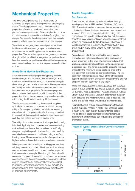
When the applied stress is plotted against the resulting<br />
strain, a curve similar to that shown in Figure 5 for Amodel<br />
ET-1000 HS resin is obtained. This is known as a "Stress-<br />
Strain" curve and is very useful in determining the short<br />
term behavior of a material when a load is applied. The<br />
curve of a ductile metal would have a similar shape.<br />
Figure 6 shows a typical stress/strain curve for a nonductile<br />
material, Amodel A-1933 PPA. Strain at failure<br />
is much lower than that of the unreinforced grade.<br />
The addition of glass fiber reinforcement improves<br />
the strength and stiffness but reduces the elongation<br />
or strain at failure.<br />
Stress, MPa<br />
Figure 5: Typical Stress/Strain Curve for Amodel<br />
ET-1000<br />
70<br />
60<br />
50<br />
40<br />
30<br />
20<br />
10<br />
0<br />
0<br />
0 5 10 15 20<br />
Strain, %<br />
10<br />
8<br />
6<br />
4<br />
2<br />
Stress, kpsi<br />
Property Data<br />
Amodel ® PPA <strong>Design</strong> <strong>Guide</strong><br />
19