Design Guide - Solvay Plastics
Design Guide - Solvay Plastics
Design Guide - Solvay Plastics
Create successful ePaper yourself
Turn your PDF publications into a flip-book with our unique Google optimized e-Paper software.
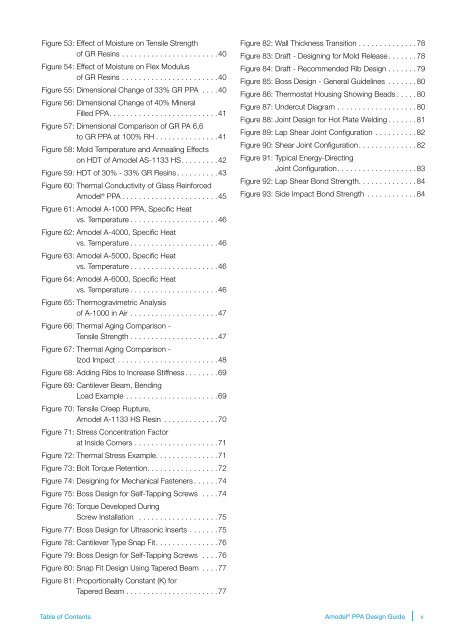
Figure 53: Effect of Moisture on Tensile Strength<br />
of GR Resins. ...................... 40<br />
Figure 54: Effect of Moisture on Flex Modulus<br />
of GR Resins . ...................... 40<br />
Figure 55: Dimensional Change of 33% GR PPA .... 40<br />
Figure 56: Dimensional Change of 40% Mineral<br />
Filled PPA. ......................... 41<br />
Figure 57: Dimensional Comparison of GR PA 6,6<br />
to GR PPA at 100% RH. .............. 41<br />
Figure 58: Mold Temperature and Annealing Effects<br />
on HDT of Amodel AS-1133 HS. ........ 42<br />
Figure 59: HDT of 30% - 33% GR Resins. ......... 43<br />
Figure 60: Thermal Conductivity of Glass Reinforced<br />
Amodel ® PPA....................... 45<br />
Figure 61: Amodel A-1000 PPA, Specific Heat<br />
vs. Temperature. .................... 46<br />
Figure 62: Amodel A-4000, Specific Heat<br />
vs. Temperature. .................... 46<br />
Figure 63: Amodel A-5000, Specific Heat<br />
vs. Temperature. .................... 46<br />
Figure 64: Amodel A-6000, Specific Heat<br />
vs. Temperature. .................... 46<br />
Figure 65: Thermogravimetric Analysis<br />
of A-1000 in Air. .................... 47<br />
Figure 66: Thermal Aging Comparison -<br />
Tensile Strength. .................... 47<br />
Figure 67: Thermal Aging Comparison -<br />
Izod Impact. ....................... 48<br />
Figure 68: Adding Ribs to Increase Stiffness. ....... 69<br />
Figure 69: Cantilever Beam, Bending<br />
Load Example. ..................... 69<br />
Figure 70: Tensile Creep Rupture,<br />
Amodel A-1133 HS Resin ............. 70<br />
Figure 71: Stress Concentration Factor<br />
at Inside Corners. ................... 71<br />
Figure 72: Thermal Stress Example. .............. 71<br />
Figure 73: Bolt Torque Retention. ................ 72<br />
Figure 74: <strong>Design</strong>ing for Mechanical Fasteners. ..... 74<br />
Figure 75: Boss <strong>Design</strong> for Self-Tapping Screws .... 74<br />
Figure 76: Torque Developed During<br />
Screw Installation ................... 75<br />
Figure 77: Boss <strong>Design</strong> for Ultrasonic Inserts. ...... 75<br />
Figure 78: Cantilever Type Snap Fit. .............. 76<br />
Figure 79: Boss <strong>Design</strong> for Self-Tapping Screws .... 76<br />
Figure 80: Snap Fit <strong>Design</strong> Using Tapered Beam .... 77<br />
Figure 81: Proportionality Constant (K) for<br />
Tapered Beam. ..................... 77<br />
Figure 82: Wall Thickness Transition. ............. 78<br />
Figure 83: Draft - <strong>Design</strong>ing for Mold Release. ...... 78<br />
Figure 84: Draft - Recommended Rib <strong>Design</strong>. ...... 79<br />
Figure 85: Boss <strong>Design</strong> - General <strong>Guide</strong>lines ....... 80<br />
Figure 86: Thermostat Housing Showing Beads. .... 80<br />
Figure 87: Undercut Diagram. .................. 80<br />
Figure 88: Joint <strong>Design</strong> for Hot Plate Welding. ...... 81<br />
Figure 89: Lap Shear Joint Configuration .......... 82<br />
Figure 90: Shear Joint Configuration. ............. 82<br />
Figure 91: Typical Energy-Directing<br />
Joint Configuration. .................. 83<br />
Figure 92: Lap Shear Bond Strength. ............. 84<br />
Figure 93: Side Impact Bond Strength. ........... 84<br />
Table of Contents<br />
Amodel ® PPA <strong>Design</strong> <strong>Guide</strong><br />
v


