Design Guide - Solvay Plastics
Design Guide - Solvay Plastics
Design Guide - Solvay Plastics

Create successful ePaper yourself
Turn your PDF publications into a flip-book with our unique Google optimized e-Paper software.
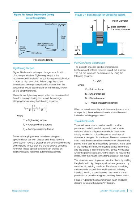
Figure 76: Torque Developed During<br />
Screw Installation<br />
Stripping Torque<br />
Figure 77: Boss <strong>Design</strong> for Ultrasonic Inserts<br />
Insert Diameter<br />
Boss diameter =<br />
2 x insert diameter<br />
Torque<br />
Thread<br />
Forming<br />
Torque<br />
Head makes contact<br />
with captured material<br />
Driving Torque<br />
Clamp<br />
Load<br />
0.7 t<br />
t<br />
Penetration Depth<br />
Tightening Torque<br />
Figure 76 shows how torque changes as a function<br />
of screw penetration. Tightening torque is the<br />
recommended installation torque for a given application.<br />
It must be high enough to fully engage the screw<br />
threads and develop clamp load but lower than the<br />
torque that would cause failure of the threads, known<br />
as the stripping torque.<br />
The optimum tightening torque value can be calculated<br />
from the average driving torque and the average<br />
stripping torque using the following equation.<br />
where<br />
1 3 1<br />
T T<br />
= T D<br />
+ T S<br />
2 2 2<br />
T T<br />
= Tightening torque<br />
T D<br />
= Average driving torque<br />
T S<br />
= Average stripping torque<br />
Some self-tapping screws have been designed<br />
specifically for use with plastics and these have the<br />
advantage of having a greater difference between driving<br />
and stripping torque than the typical screws designed<br />
for metal. These special fasteners can provide an<br />
additional safety factor for automated assembly.<br />
Pull Out Force Calculation<br />
The strength of a joint can be characterized<br />
by the amount of force required to pull-out a screw.<br />
The pull out force can be estimated by using the<br />
following equation:<br />
where<br />
F = πSDL<br />
F = Pull out force<br />
S = Shear strength<br />
D = Pitch diameter<br />
L = Thread engagement length<br />
When repeated assembly and disassembly are required<br />
or expected, threaded metal inserts should be used<br />
instead of self-tapping screws.<br />
Threaded Inserts<br />
Threaded metal inserts can be used to provide<br />
permanent metal threads in a plastic part; a wide<br />
variety of sizes and types are available. Inserts are<br />
usually installed in molded bosses whose internal<br />
diameter is designed for the insert. The most commonly<br />
used metal inserts are either molded-in or ultrasonically<br />
placed in the part as a secondary operation. In the case<br />
of the molded-in insert, the insert is placed in the mold<br />
and the plastic is injected around it. Stress will develop<br />
when the plastic cools around the insert. To reduce this<br />
stress, heat the inserts to the temperature of the mold.<br />
The ultrasonic insert is pressed into the plastic by melting<br />
the plastic with high frequency vibrations, generated by<br />
an ultrasonic welding machine. The ultrasonic welding<br />
melts material around the metal insert as it is being<br />
installed, forming a bond between the insert and the<br />
plastic that is usually strong and relatively free of stress.<br />
Figure 77 depicts the recommended insert and boss<br />
designs for use with Amodel ® PPA resin.<br />
<strong>Design</strong> Information<br />
Amodel ® PPA <strong>Design</strong> <strong>Guide</strong><br />
75