Design Guide - Solvay Plastics
Design Guide - Solvay Plastics
Design Guide - Solvay Plastics

You also want an ePaper? Increase the reach of your titles
YUMPU automatically turns print PDFs into web optimized ePapers that Google loves.
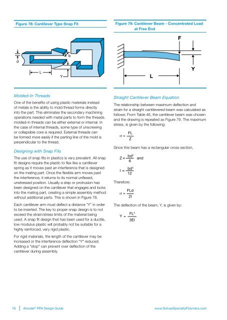
Figure 78: Cantilever Type Snap Fit<br />
Figure 79: Cantilever Beam - Concentrated Load<br />
at Free End<br />
F<br />
b<br />
d<br />
L<br />
Y<br />
L<br />
Y<br />
Molded-In Threads<br />
One of the benefits of using plastic materials instead<br />
of metals is the ability to mold thread forms directly<br />
into the part. This eliminates the secondary machining<br />
operations needed with metal parts to form the threads.<br />
molded-in threads can be either external or internal. In<br />
the case of internal threads, some type of unscrewing<br />
or collapsible core is required. External threads can<br />
be formed more easily if the parting line of the mold is<br />
perpendicular to the thread.<br />
<strong>Design</strong>ing with Snap Fits<br />
The use of snap fits in plastics is very prevalent. All snap<br />
fit designs require the plastic to flex like a cantilever<br />
spring as it moves past an interference that is designed<br />
on the mating part. Once the flexible arm moves past<br />
the interference, it returns to its normal unflexed,<br />
unstressed position. Usually a step or protrusion has<br />
been designed on the cantilever that engages and locks<br />
into the mating part, creating a simple assembly method<br />
without additional parts. This is shown in Figure 78.<br />
Each cantilever arm must deflect a distance “Y” in order<br />
to be inserted. The key to proper snap design is to not<br />
exceed the strain/stress limits of the material being<br />
used. A snap fit design that has been used for a ductile,<br />
low modulus plastic will probably not be suitable for a<br />
highly reinforced, very rigid plastic.<br />
For rigid materials, the length of the cantilever may be<br />
increased or the interference deflection "Y" reduced.<br />
Adding a "stop" can prevent over deflection of the<br />
cantilever during assembly.<br />
Straight Cantilever Beam Equation<br />
The relationship between maximum deflection and<br />
strain for a straight cantilevered beam was calculated as<br />
follows: From Table 46, the cantilever beam was chosen<br />
and the drawing is repeated as Figure 79. The maximum<br />
stress, is given by the following:<br />
σ = FL<br />
Z<br />
Since this beam has a rectangular cross section,<br />
Z =<br />
I =<br />
Therefore:<br />
bd 2<br />
6<br />
bd 3<br />
12<br />
σ = FLd<br />
2I<br />
and<br />
The deflection of the beam, Y, is given by:<br />
Y =<br />
FL 3<br />
3EI<br />
76 Amodel ® PPA <strong>Design</strong> <strong>Guide</strong><br />
www.<strong>Solvay</strong>SpecialtyPolymers.com