Design Guide - Solvay Plastics
Design Guide - Solvay Plastics
Design Guide - Solvay Plastics

You also want an ePaper? Increase the reach of your titles
YUMPU automatically turns print PDFs into web optimized ePapers that Google loves.
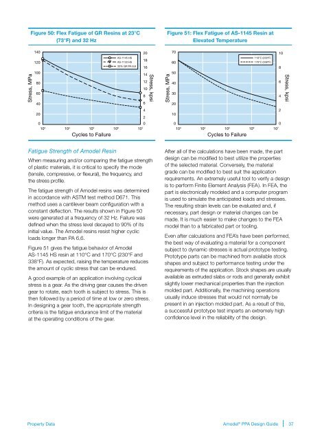
Figure 50: Flex Fatigue of GR Resins at 23°C<br />
(73°F) and 32 Hz<br />
Figure 51: Flex Fatigue of AS-1145 Resin at<br />
Elevated Temperature<br />
Stress, MPa<br />
140<br />
120<br />
100<br />
80<br />
60<br />
40<br />
20<br />
0<br />
AS-1145 HS<br />
AS-1133 HS<br />
33% GR PA 6,6<br />
10 3 10 4 10 5 10 6 10 7<br />
Cycles to Failure<br />
20<br />
18<br />
16<br />
14<br />
12<br />
10<br />
8<br />
6<br />
4<br />
2<br />
0<br />
Stress, kpsi<br />
Stress, MPa<br />
70<br />
60<br />
50<br />
40<br />
30<br />
20<br />
10<br />
0<br />
110°C (230°F)<br />
170°C (338°F)<br />
10 3 10 4 10 5 10 6 10 7<br />
Cycles to Failure<br />
10<br />
8<br />
6<br />
4<br />
2<br />
0<br />
Stress, kpsi<br />
Fatigue Strength of Amodel Resin<br />
When measuring and/or comparing the fatigue strength<br />
of plastic materials, it is critical to specify the mode<br />
(tensile, compressive, or flexural), the frequency, and<br />
the stress profile.<br />
The fatigue strength of Amodel resins was determined<br />
in accordance with ASTM test method D671. This<br />
method uses a cantilever beam configuration with a<br />
constant deflection. The results shown in Figure 50<br />
were generated at a frequency of 32 Hz. Failure was<br />
defined when the stress level decayed to 90% of its<br />
initial value. The Amodel resins resist higher cyclic<br />
loads longer than PA 6,6.<br />
Figure 51 gives the fatigue behavior of Amodel<br />
AS-1145 HS resin at 110°C and 170°C (230°F and<br />
338°F). As expected, raising the temperature reduces<br />
the amount of cyclic stress that can be endured.<br />
A good example of an application involving cyclical<br />
stress is a gear. As the driving gear causes the driven<br />
gear to rotate, each tooth is subject to stress. This is<br />
then followed by a period of time at low or zero stress.<br />
In designing a gear tooth, the appropriate strength<br />
criteria is the fatigue endurance limit of the material<br />
at the operating conditions of the gear.<br />
After all of the calculations have been made, the part<br />
design can be modified to best utilize the properties<br />
of the selected material. Conversely, the material<br />
grade can be modified to best suit the application<br />
requirements. An extremely useful tool to verify a design<br />
is to perform Finite Element Analysis (FEA). In FEA, the<br />
part is electronically modeled and a computer program<br />
is used to simulate the anticipated loads and stresses.<br />
The resulting strain levels can be evaluated and, if<br />
necessary, part design or material changes can be<br />
made. It is much easier to make changes to the FEA<br />
model than to a fabricated part or tooling.<br />
Even after calculations and FEA’s have been performed,<br />
the best way of evaluating a material for a component<br />
subject to dynamic stresses is actual prototype testing.<br />
Prototype parts can be machined from available stock<br />
shapes and subject to performance testing under the<br />
requirements of the application. Stock shapes are usually<br />
available as extruded slabs or rods and generally exhibit<br />
slightly lower mechanical properties than the injection<br />
molded part. Additionally, the machining operations<br />
usually induce stresses that would not normally be<br />
present in an injection molded part. As a result of this,<br />
a successful prototype test imparts an extremely high<br />
confidence level in the reliability of the design.<br />
Property Data<br />
Amodel ® PPA <strong>Design</strong> <strong>Guide</strong><br />
37