Design Guide - Solvay Plastics
Design Guide - Solvay Plastics
Design Guide - Solvay Plastics

Create successful ePaper yourself
Turn your PDF publications into a flip-book with our unique Google optimized e-Paper software.
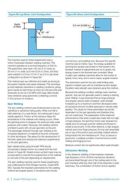
Figure 89: Lap Shear Joint Configuration<br />
Figure 90: Shear Joint Configuration<br />
Depth<br />
of Weld<br />
0.2 mm (0.008 in.)<br />
30° - 45°<br />
Interference<br />
The machine used for these experiments was a<br />
Vinton Hydroweld Vibration welding machine. This<br />
machine operates at a nominal frequency of 240 Hz.<br />
The specimens used were 102 mm (4 in.) long, by<br />
25 mm (1 in.) wide, by 6 mm (0.25 in.) thick, and they<br />
were welded in a 25 by 13 mm (1 by 0.5 in.) lap shear<br />
configuration as shown in Figure 89.<br />
This method was very effective and welds as strong as<br />
the parent material were easily obtained. This technique<br />
proved relatively insensitive to welding conditions, giving<br />
good results at weld times as short as 0.60 seconds and<br />
pressures as low as 2.20 MPa (320 psig). Best results<br />
were obtained using specimens containing a normal<br />
(1.8%) amount of moisture.<br />
Spin Welding<br />
The spin welding method uses frictional heat to join two<br />
cylindrical or spherical mating parts. While one half is<br />
held stationary in a nest fixture, the mating part is spun<br />
rapidly against it. Friction at the interface raises the<br />
temperature of the material until melting occurs. When<br />
the spinning action is stopped, the parts are held under<br />
pressure until cooled. Obviously, this welding method<br />
is limited to parts with circular geometry at the joint.<br />
The advantage obtained through spin welding is the<br />
increased dispersion of material at the joint compared<br />
to other techniques. This allows for the development of<br />
hermetic seals and reduces the tolerance requirements<br />
on the joint geometry.<br />
Spin welded joints using Amodel ® PPA should<br />
incorporate a design known as a shear joint like that<br />
shown in Figure 90. Details known as flash traps may be<br />
incorporated to channel the localized flow of the material<br />
to one side of the part depending on requirements.<br />
The spin welding machine used for these experiments<br />
was a Mechasonic KLN Omega machine, model SPN-<br />
063. Typically the important parameters for this welding<br />
method are angular speed, in revolutions per minute,<br />
normal force, and welding time. Because this specific<br />
machine was an inertia- type, the energy available for<br />
spinning the sample was limited to that stored in the<br />
flywheel. Instead of adjustments per se to speed, the<br />
energy stored in the flywheel was controlled. More<br />
modern spin welding machines allow for the control of<br />
speed, force, time, and in some cases, angular location.<br />
The specimens used for the spin weld testing were<br />
injection molded cups with an interference joint design.<br />
Excellent weld strength was obtained using this method.<br />
Because the welding condition settings were machinespecific,<br />
they are not generally useful in setting a starting<br />
point. Rather, it was observed that as forge pressure<br />
and angular velocity were increased, weld strength<br />
increased up to a maximum and then decreased when<br />
an excessive amount of either pressure or velocity were<br />
applied. The values for these parameters are strictly<br />
dependent on the part geometry and therefore they<br />
are not noted here. The explanation of the observed<br />
phenomena is that when a weld was made with too high<br />
a forge pressure, the spinning motion was stopped too<br />
rapidly and not enough polymer melted and flowed to<br />
create a sound joint. In the other extreme, a high angular<br />
velocity and a low forge pressure, the top part essentially<br />
sat on top of the bottom part and freely rotated without<br />
being forced into the interference fit. Thus, to assure a<br />
good joint, a welding condition must be found so both<br />
melting and forging occurs.<br />
Moisture content did not significantly affect weld strength.<br />
Ultrasonic Welding<br />
In the ultrasonic welding of thermoplastic materials,<br />
high frequency (10 to 40 KHz) mechanical vibrations<br />
are transmitted through one of the mating parts to the<br />
joint interface while the other half of the assembly is held<br />
stationary. The combination of friction and an applied<br />
82 Amodel ® PPA <strong>Design</strong> <strong>Guide</strong><br />
www.<strong>Solvay</strong>SpecialtyPolymers.com