Design Guide - Solvay Plastics
Design Guide - Solvay Plastics
Design Guide - Solvay Plastics

Create successful ePaper yourself
Turn your PDF publications into a flip-book with our unique Google optimized e-Paper software.
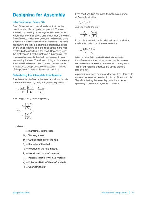
<strong>Design</strong>ing for Assembly<br />
Interference or Press Fits<br />
One of the most economical methods that can be<br />
used to assemble two parts is a press fit. The joint is<br />
achieved by pressing or forcing the shaft into a hole<br />
whose diameter is smaller than the diameter of the shaft.<br />
The difference in diameter between the hole and shaft<br />
is referred to as the diametrical interference. The force<br />
maintaining the joint is primarily a compressive stress<br />
on the shaft resulting from the hoop stress in the hub<br />
created by the insertion of the shaft. Depending upon<br />
the relative moduli of the shaft and hub materials, the<br />
compressive stress in the shaft can also contribute to<br />
maintaining the joint. The stress holding an interference<br />
fit will exhibit relaxation over time in a manner that is<br />
analogous to creep, because the apparent modulus<br />
of the polymeric material decreases over time.<br />
Calculating the Allowable Interference<br />
The allowable interference between a shaft and a hub<br />
can be determined by using the general equation:<br />
If the shaft and hub are made from the same grade<br />
of Amodel resin, then:<br />
E h<br />
= E S<br />
= E<br />
and the interference is:<br />
I =<br />
S d<br />
E<br />
D S<br />
F+1<br />
F<br />
If the hub is made from Amodel resin and the shaft is<br />
made from metal, then the interference is:<br />
I = S d D S<br />
F<br />
F + υ h<br />
E h<br />
When a press fit is used with dissimilar materials,<br />
the differences in thermal expansion can increase or<br />
decrease the interference between two mating parts.<br />
This could increase or reduce the stress affecting<br />
joint strength.<br />
A press fit can creep or stress relax over time. This could<br />
cause a decrease in the retention force of the assembly.<br />
Therefore, testing the assembly under its expected<br />
operating conditions is highly recommended.<br />
S d<br />
D I<br />
s<br />
F + υ<br />
=<br />
h<br />
+<br />
F<br />
E h<br />
1 − υ s<br />
E s<br />
and the geometry factor is given by:<br />
2<br />
D<br />
1+<br />
S<br />
Dh<br />
F =<br />
2<br />
D<br />
1−<br />
S<br />
Dh<br />
where<br />
I = Diametrical interference<br />
S d<br />
= Working stress<br />
D h<br />
= Outside diameter of the hub<br />
D S<br />
= Diameter of the shaft<br />
E h<br />
= Modulus of the hub material<br />
E S<br />
= Modulus of the shaft material<br />
υ h<br />
= Poisson’s Ratio of the hub material<br />
υ S<br />
= Poisson’s Ratio of the shaft material<br />
F = Geometry factor<br />
<strong>Design</strong> Information<br />
Amodel ® PPA <strong>Design</strong> <strong>Guide</strong><br />
73