Design Guide - Solvay Plastics
Design Guide - Solvay Plastics
Design Guide - Solvay Plastics
You also want an ePaper? Increase the reach of your titles
YUMPU automatically turns print PDFs into web optimized ePapers that Google loves.
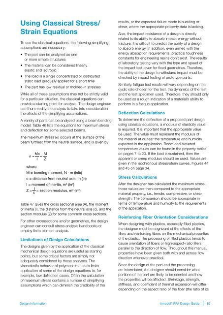
Using Classical Stress/<br />
Strain Equations<br />
To use the classical equations, the following simplifying<br />
assumptions are necessary:<br />
• The part can be analyzed as one<br />
or more simple structures<br />
• The material can be considered linearly<br />
elastic and isotropic<br />
• The load is a single concentrated or distributed<br />
static load gradually applied for a short time<br />
• The part has low residual or molded-in stresses<br />
While all of these assumptions may not be strictly valid<br />
for a particular situation, the classical equations can<br />
provide a starting point for analysis. The design engineer<br />
can then modify the analysis to take into consideration<br />
the effects of the simplifying assumptions.<br />
A variety of parts can be analyzed using a beam bending<br />
model. Table 46 lists the equations for maximum stress<br />
and deflection for some selected beams.<br />
The maximum stress (σ) occurs at the surface of the<br />
beam furthest from the neutral surface, and is given by:<br />
σ = Mc =<br />
I<br />
M<br />
Z<br />
where<br />
M = bending moment, N · m (inlb)<br />
c = distance from neutral axis, m (in)<br />
I = moment of inertia, m 4 (in 4 )<br />
Z = I = section modulus, m 3 (in 3 )<br />
c<br />
Table 47 gives the cross sectional area (A), the moment<br />
of inertia (I), the distance from the neutral axis (c), and the<br />
section modulus (Z) for some common cross sections.<br />
For other crosssections and/or geometries, the design<br />
engineer can consult stress analysis handbooks or<br />
employ finite element analysis.<br />
Limitations of <strong>Design</strong> Calculations<br />
The designs given by the application of the classical<br />
mechanical design equations are useful as starting<br />
points, but some critical factors are simply not<br />
adequately considered by these analyses. The<br />
viscoelastic behavior of polymeric materials limits<br />
application of some of the design equations to, for<br />
example, low deflection cases. Often the calculation<br />
of maximum stress contains a number of simplifying<br />
assumptions which can diminish the credibility of the<br />
results, or the expected failure mode is buckling or<br />
shear, where the appropriate property data is lacking.<br />
Also, the impact resistance of a design is directly<br />
related to its ability to absorb impact energy without<br />
fracture. It is difficult to predict the ability of a design<br />
to absorb energy. In addition, even armed with the<br />
energy absorption requirements, practical toughness<br />
constants for engineering resins don’t exist. The results<br />
of laboratory testing vary with the type and speed of<br />
the impact test, even for fixed geometries. Therefore,<br />
the ability of the design to withstand impact must be<br />
checked by impact testing of prototype parts.<br />
Similarly, fatigue test results will vary depending on the<br />
cyclic rate chosen for the test, the dynamics of the test,<br />
and the test specimen used. Therefore, they should only<br />
be used as a rough indication of a material’s ability to<br />
perform in a fatigue application.<br />
Deflection Calculations<br />
To determine the deflection of a proposed part design<br />
using classical equations, a modulus of elasticity value<br />
is required. It is important that the appropriate value<br />
be used. The value must represent the modulus of<br />
the material at or near the temperature and humidity<br />
expected in the application. Room and elevated<br />
temperature values can be found in the property tables<br />
on pages 7 to 20. If the load is sustained, then the<br />
apparent or creep modulus should be used. Values are<br />
given in the isochronous stress/strain curves, Figures 44<br />
and 45 on page 34.<br />
Stress Calculations<br />
After the designer has calculated the maximum stress,<br />
those values are then compared to the appropriate<br />
material property, i.e., tensile, compressive, or shear<br />
strength. The comparison should be appropriate in<br />
terms of temperature and humidity to the requirements<br />
of the application.<br />
Reinforcing Fiber Orientation Considerations<br />
When designing with plastics, especially filled plastics,<br />
the designer must be cognizant of the effects of the<br />
fillers and reinforcing fibers on the mechanical properties<br />
of the plastic. The processing of filled plastics tends to<br />
cause orientation of fibers or high-aspect-ratio fillers<br />
parallel to the direction of flow. Throughout this manual,<br />
properties have been given both with and across flow<br />
direction whenever practical.<br />
Since the design of the part and the processing<br />
are interrelated, the designer should consider what<br />
portions of the part are likely to be oriented and how<br />
the properties will be affected. Shrinkage, strength,<br />
stiffness, and coefficient of thermal expansion will differ<br />
depending on the aspect ratio of the fiber (the ratio of its<br />
<strong>Design</strong> Information<br />
Amodel ® PPA <strong>Design</strong> <strong>Guide</strong><br />
67


