You also want an ePaper? Increase the reach of your titles
YUMPU automatically turns print PDFs into web optimized ePapers that Google loves.
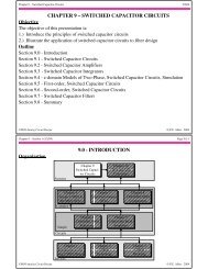
Chapter 6 – Section 2 (5/2/04) Page 6.2-8<br />
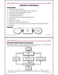
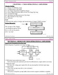
Miller Compensation of the Two-Stage Op Amp<br />
V DD<br />
V CC<br />
M3<br />
M1<br />
-<br />
M2<br />
v in<br />
+<br />
+<br />
VBias<br />
-<br />
C M<br />
M5<br />
M4<br />
V SS<br />
Q3 Q4<br />
M6<br />
C M<br />
Q6<br />
C c v out<br />
C c v out<br />
-<br />
Q1 Q2<br />
C<br />
v I<br />
C II in C<br />
+<br />
I<br />
C II<br />
M7<br />
+<br />
VBias<br />
-<br />
The various capacitors are:<br />
C c = accomplishes the Miller compensation<br />
C M = capacitance associated with the first-stage mirror (mirror pole)<br />
C I = output capacitance to ground of the first-stage<br />
C II = output capacitance to ground of the second-stage<br />
Q5<br />
V EE<br />
Q7<br />
Fig. 120-08<br />
CMOS <strong>Analog</strong> Circuit <strong>Design</strong> © P.E. Allen - 2004<br />
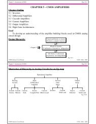
Chapter 6 – Section 2 (5/2/04) Page 6.2-9<br />
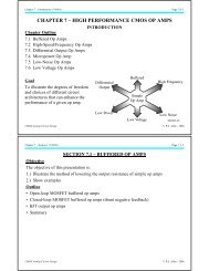
Compensated Two-Stage, Small-Signal Frequency Response Model Simplified<br />
Use the CMOS op amp to illustrate:<br />
1.) Assume that g m3 >> g ds3 + g ds1<br />
2.) Assume that g m3<br />
C M<br />
>> GB<br />
Therefore,<br />
v 1 v2<br />
C c<br />
+<br />
-g m1 v in<br />
2 1 g m2 v in<br />
C M g m3 2 g m4 v 1<br />
C 1 rds2 ||r ds4<br />
g m6 v 2 r ds6 ||r ds7 C L<br />
v out<br />
-<br />
r ds1 ||r ds3<br />
g m1 v in rds2 ||r ds4<br />
g m6 v 2 rds6 ||r ds7<br />
C II<br />
+<br />
v in<br />
-<br />
CI<br />
C c<br />
v 2<br />
+<br />
v out<br />
-<br />
Fig. 120-09<br />
Same circuit holds for the BJT op amp with different component relationships.<br />
CMOS <strong>Analog</strong> Circuit <strong>Design</strong> © P.E. Allen - 2004