You also want an ePaper? Increase the reach of your titles
YUMPU automatically turns print PDFs into web optimized ePapers that Google loves.
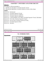
Chapter 6 – Section 2 (5/2/04) Page 6.2-32<br />
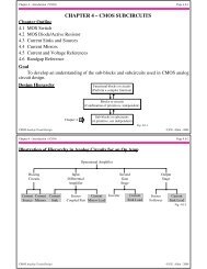
Slew Rate of a Two-Stage CMOS Op Amp<br />
Remember that slew rate occurs when currents flowing in a capacitor become limited and<br />
is given as<br />
I lim = C dv C<br />
dt where v C is the voltage across the capacitor C.<br />
-<br />
v in >>0<br />
+<br />
M3<br />
M1<br />
+<br />
VBias<br />
-<br />
I 5<br />
M4<br />
M2<br />
M5<br />
V DD<br />
V SS<br />
Positive Slew Rate<br />
C c I5<br />
Assume a<br />
virtural<br />
ground<br />
M6<br />
I 6 I CL<br />
C L<br />
I 7<br />
M7<br />
v out<br />
-<br />
v in I 5 SR- = min⎢<br />
⎥<br />
⎣<br />
C c<br />
, I 7-I 5<br />
C L<br />
= I 5<br />
⎦ Cc if I 7 >>I 5 .<br />
Therefore, if C L is not too large and if I 7 is significantly greater than I 5 , then the slew rate<br />
of the two-stage op amp should be,<br />
SR = I 5<br />
Cc<br />
v out<br />
Chapter 6 – Section 3 (5/2/04) Page 6.3-1<br />
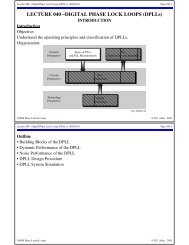
SECTION 6.3 - TWO-STAGE OP AMP DESIGN<br />
Unbuffered, Two-Stage CMOS Op Amp<br />
V DD<br />
M3<br />
M4<br />
C c<br />
M6<br />
v out<br />
Notation:<br />
- M1 M2<br />
v in<br />
+<br />
+<br />
VBias<br />
-<br />
M5<br />
V SS<br />
M7<br />
C L<br />
Fig. 6.3-1<br />
S i = W i<br />
L i<br />
= W/L of the ith transistor<br />
CMOS <strong>Analog</strong> Circuit <strong>Design</strong> © P.E. Allen - 2004