Valent_IOM_Controls - RJI-Sales.com
Valent_IOM_Controls - RJI-Sales.com
Valent_IOM_Controls - RJI-Sales.com
Create successful ePaper yourself
Turn your PDF publications into a flip-book with our unique Google optimized e-Paper software.
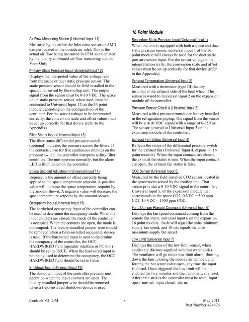
Air Flow Measuring Station (Universal Input 11)<br />
Measured by the either the Inlet cone sensor or AMD<br />
damper located in the outside air inlet. This is the<br />
actual air flow being measured in CFM as calculated<br />
by the factory calibrated air flow measuring station.<br />
View Only<br />
Primary Static Pressure Input (Universal Input 12)<br />
Displays the interpreted value of the voltage read<br />
from the space or duct static pressure sensor. The<br />
static pressure sensor should be field installed in the<br />
space/duct served by the rooftop unit. The output<br />
signal from the sensor must be 0-10 VDC. The space<br />
/ duct static pressure sensor, when used, must be<br />
connected to Universal Input 12 on the 34 point<br />
module depending on the configuration of the<br />
ventilator. For the sensor voltage to be interpreted<br />
correctly, the conversion scale and offset values must<br />
be set up correctly for that device (refer to the<br />
Appendix).<br />
Filter Status Input (Universal Input 13)<br />
The filter status differential pressure switch<br />
(optional) indicates the pressure across the filters. If<br />
the contacts close for five continuous minutes on the<br />
pressure switch, the controller interprets a dirty filter<br />
condition. The unit operates normally, but the alarm<br />
LED is illuminated on the controller.<br />
Space Setpoint Adjustment (Universal Input 14)<br />
Represents the amount of offset currently being<br />
applied to the space temperature setpoint. A positive<br />
value will increase the space temperature setpoint by<br />
the amount shown. A negative value will decrease the<br />
space temperature setpoint by the amount shown.<br />
Occupancy Input (Universal Input 15)<br />
The hardwired occupancy input of the controller can<br />
be used to determine the occupancy mode. When the<br />
input contacts are closed, the mode of the controller<br />
is occupied. When the contacts are open, the mode is<br />
unoccupied. The factory-installed jumper wire should<br />
be removed when a field-installed occupancy device<br />
is used. If the hardwired input is used to determine<br />
the occupancy of the controller, the OCC<br />
HARDWIRED field (operator interface or PC tool)<br />
should be set to TRUE. When the hardwired input is<br />
not being used to determine the occupancy, the OCC<br />
HARDWIRED field should be set to False<br />
Shutdown Input (Universal Input 16)<br />
The shutdown input of the controller prevents unit<br />
operation when the input contacts are open. The<br />
factory-installed jumper wire should be removed<br />
when a field-installed shutdown device is used.<br />
16 Point Module<br />
Secondary Static Pressure Input (Universal Input 1)<br />
When the unit is equipped with both a space and duct<br />
static pressure sensor, universal input 1 of the 16<br />
point module will always be used for the duct static<br />
pressure sensor input. For the sensor voltage to be<br />
interpreted correctly, the conversion scale and offset<br />
values must be set up correctly for that device (refer<br />
to the Appendix).<br />
Exhaust Temperature (Universal Input 2)<br />
Measured with a thermistor (type III) factory<br />
installed at the exhaust side of the heat wheel. The<br />
sensor is wired to Universal Input 2 on the expansion<br />
module of the controller.<br />
Pressure Sensor Circuit A (Universal Input 3)<br />
Measured with a pressure transducer factory installed<br />
in the refrigeration piping. The signal from the sensor<br />
will be a 0-10 VDC signal with a range of 0-750 psi.<br />
The sensor is wired to Universal Input 3 on the<br />
expansion module of the controller.<br />
Exhaust Fan Status (Universal Input 4)<br />
Reflects the status of the differential pressure switch<br />
for the exhaust fan (Universal Input 4, expansion 16<br />
point module). When the input contacts are closed,<br />
the exhaust fan status is true. When the input contacts<br />
are open, the exhaust fan status is false.<br />
CO2 Sensor (Universal Input 5)<br />
Measured by the field installed CO2 sensor located in<br />
the space/room served by the rooftop unit. That<br />
sensor provides a 0-10 VDC signal to the controller,<br />
Universal Input 5, of the expansion module that<br />
corresponds to the space CO2: 0 VDC = 500 ppm<br />
CO2, 10 VDC = 1500 ppm CO2.<br />
Fan / Damper Remote Command (Universal Input 6)<br />
Displays the fan speed <strong>com</strong>mand <strong>com</strong>ing from the<br />
remote fan input, universal input 6 on the expansion<br />
16 point module. 0vdc will equal the units minimum<br />
supply fan speed, and 10 vdc equals the units<br />
maximum supply fan speed.<br />
Low Limit (Universal Input 7)<br />
Displays the status of the low limit sensor, when<br />
applicable (factory supplied with hot water coils).<br />
The ventilator will go into a low limit alarm, shutting<br />
down the fans, closing the outside air damper, and<br />
forcing the hot water valve open, any time the input<br />
is closed. Once triggered the low limit will be<br />
enabled for five minutes and then automatically reset.<br />
After three strikes the controller must be reset. Input<br />
open=normal, input closed=alarm.<br />
<strong>Controls</strong> V2 <strong>IOM</strong> 8 May 2011<br />
Part Number 474626


