Valent_IOM_Controls - RJI-Sales.com
Valent_IOM_Controls - RJI-Sales.com
Valent_IOM_Controls - RJI-Sales.com

You also want an ePaper? Increase the reach of your titles
YUMPU automatically turns print PDFs into web optimized ePapers that Google loves.
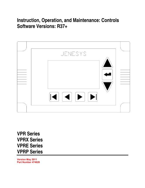
Instruction, Operation, and Maintenance: <strong>Controls</strong><br />
Software Versions: R37+<br />
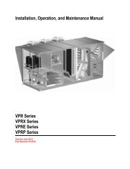
VPR Series<br />
VPRX Series<br />
VPRE Series<br />
VPRP Series<br />
Version May 2011<br />
Part Number 474626
Table of Contents<br />
Safety ............................................................................................................................................................................................... 3<br />
Special Design Requests ............................................................................................................................................................... 3<br />
Warranty Documentation ............................................................................................................................................................... 4<br />
I/O Configuration............................................................................................................................................................................. 5<br />
Universal Inputs............................................................................................................................................................................ 5<br />
Digital Outputs ............................................................................................................................................................................ 10<br />
Analog Outputs........................................................................................................................................................................... 11<br />
LCD Settings ................................................................................................................................................................................. 12<br />
Basic Functions .......................................................................................................................................................................... 13<br />
Advance Adjustment................................................................................................................................................................... 17<br />
Setpoint Descriptors ................................................................................................................................................................... 18<br />
Universal Maintenance Tool (UMT) Settings.............................................................................................................................. 45<br />
Basic Functions .......................................................................................................................................................................... 47<br />
Advanced Functions ................................................................................................................................................................... 49<br />
NDIO Network ............................................................................................................................................................................ 53<br />
BACnet IP Communication Guide............................................................................................................................................. 102<br />
BACnet IP Points List ............................................................................................................................................................... 104<br />
BACnet MSTP Communication Guide ...................................................................................................................................... 107<br />
BACnet MSTP Points List......................................................................................................................................................... 109<br />
LonTalk Communication Guide................................................................................................................................................. 112<br />
LonTalk Points List ................................................................................................................................................................... 113<br />
Web User Interface (Web UI) Installation and Operation ........................................................................................................ 116<br />
Initial Setup............................................................................................................................................................................... 116<br />
Basic Functions ........................................................................................................................................................................ 121<br />
Advanced Functions ................................................................................................................................................................. 123<br />
Sequence of Control................................................................................................................................................................... 124<br />
<strong>Controls</strong> V2 <strong>IOM</strong> 2 May 2011<br />
Part Number 474626
Safety<br />
WARNING:<br />
Improper installation, adjustment, service, maintenance, or alteration can cause property damage, personal injury,<br />
or loss of life. Installation, startup, and service must be performed by a qualified installer, service agency,<br />
or gas supplier.<br />
The customer must provide proper equipment and fully-trained installers to follow local safety requirements when<br />
receiving, installing, or servicing equipment. Consult all local building, electrical, occupational safety, and gas<br />
codes.<br />
Lock out all power supplies before servicing the unit to prevent accidental startup. All fan blades should be secured<br />
to prevent wind rotation. Remove any restrictive device before restoring power.<br />
The Clean Air Act of 1990 bans the intentional venting of refrigerant (CFC and HCFC) as of July 1, 1992.<br />
Approved methods of recovery, recycling, or reclaiming refrigerant must be followed. Fines and/or incarceration<br />
may be levied for non-<strong>com</strong>pliance.<br />
Special Design Requests<br />
VPR, VPRE, VPRP and VPRX units are occasionally built with special features requested by the customer. This<br />
manual does not reflect any Special Design Requests and only covers standard options.<br />
<strong>Controls</strong> V2 <strong>IOM</strong> 3 May 2011<br />
Part Number 474626
Warranty Documentation<br />
Manufacturer warrants to the original purchaser that the manufacturer's equipment will be free from defects in<br />
material and workmanship if installed, maintained and operated under normal conditions of service in accordance<br />
with the instructions of the manufacturer for the following periods:<br />
▪ Overall unit - for a period of one year from the date of original installation but, in no event, for longer than<br />
eighteen months from the date of shipment from its factory<br />
▪ Compressors - for a period of five years from the date of original installation but, in no event, for longer than 66<br />
months from the date of shipment from its factory<br />
Manufacturer will repair or replace, F.O.B. factory, without charge, any part it has manufactured or supplied which<br />
upon examination at its factory shall prove to have been defective. This warranty may not be assigned or transferred.<br />
No allegedly defective part or <strong>com</strong>ponent may be returned to the manufacturer without its prior written<br />
authorization.<br />
WARRANTY DOES NOT INCLUDE LABOR CHARGES INCURRED IN THE REMOVAL, REPLACEMENT<br />
OR ADJUSTMENT OF DEFECTIVE PARTS OR COMPONENTS, NOR TRANSPORTATION CHARGES<br />
INCURRED IN RETURNING ALLEGEDLY DEFECTIVE PARTS OR COMPONENTS TO THE LOCATION<br />
OF THE EQUIPMENT. No warranty herein extended shall apply to correction of conditions arising from improper<br />
or incorrectly connected air duct, piping, wiring, power supply, blown fuses, freezing, or any other condition<br />
resulting from improper installation, operation, or maintenance by anyone other than the manufacturer's employee or<br />
its representative. The foregoing warranty shall not apply if damage results from any contingency beyond the<br />
manufacturer's control, not to equipment installed outside of the boundaries of the Continental U.S.A., Canada, or<br />
Alaska unless specifically noted in writing by the manufacturer, nor to equipment which has been tampered with or<br />
altered or upon which, or any <strong>com</strong>ponent of which, any serial number has been altered, defaced or removed.<br />
The manufacturer shall not be liable to the original Purchaser of any third person for any consequential, secondary,<br />
or incidental damages due to or resulting from the design, construction, installation, servicing, or operation of the<br />
warranted equipment or for any other cause whatsoever. THE WARRANTIES HEREIN SET FORTH ARE IN<br />
LIEU OF ALL OTHER WARRANTIES, EXPRESS OR IMPLIED, AND ALL OTHER OBLIGATIONS OR<br />
LIABILITIES ON THE PART OF THE MANUFACTURER.<br />
The manufacturer neither assumes nor authorizes any person to assume for it any other obligation or liability in<br />
connection with warranted equipment or any part thereof. THE MANUFACTURER HEREBY EXCLUDES THE<br />
IMPLIED WARRANTY OF MERCHANTABILITY. THE MANUFACTURER HEREBY EXCLUDES THE<br />
IMPLIED WARRANTY OF FITNESS FOR ANY PARTICULAR PURPOSE FROM ANY SALE MADE TO<br />
THE PURCHASER.<br />
<strong>Controls</strong> V2 <strong>IOM</strong> 4 May 2011<br />
Part Number 474626
I/O Configuration<br />
Universal Inputs<br />
34 Point Module<br />
Universal Input Terminals Notes<br />
1 Supply Air Temperature<br />
2 Cooling Coil Leaving Air Temperature<br />
3 Outside Air Temperature<br />
4 Space Temperature<br />
5 Outside Air Relative Humidity<br />
6 Space Relative Humidity<br />
7 Damper End Switch<br />
8 Supply Fan Status<br />
9 High Pressure Cutout, Circuit A<br />
10 Low Pressure Cutout, Circuit A<br />
11 High Pressure Cutout, Circuit B<br />
12 Low Pressure Cutout, Circuit B<br />
13 Filter Status<br />
14 (not used)<br />
15 Occupancy Input<br />
16 Shutdown Input<br />
U1<br />
0V<br />
0V<br />
U2<br />
U3<br />
0V<br />
0V<br />
U4<br />
U5<br />
0V<br />
0V<br />
U6<br />
U7<br />
0V<br />
0V<br />
U8<br />
U9<br />
0V<br />
0V<br />
U10<br />
U11<br />
0V<br />
0V<br />
U12<br />
U13<br />
0V<br />
0V<br />
U14<br />
U15<br />
0V<br />
0V<br />
U16<br />
10kΩ Thermistor, Type III<br />
10kΩ Thermistor, Type III<br />
10kΩ Thermistor, Type III<br />
10kΩ Thermistor, Type III<br />
0-10 VDC (0-100%)<br />
0-10 VDC (0-100%)<br />
Contact Closed = End Switch(es) Made, Damper(s) OPEN<br />
Contact Closed = Fan ON<br />
Contact Closed = Normal<br />
Contact Closed = Normal<br />
Contact Closed = Normal<br />
Contact Closed = Normal<br />
Contact Closed = Dirty Filter<br />
Contact Closed = Occupied<br />
Contact Closed = Run<br />
<strong>Controls</strong> V2 <strong>IOM</strong> 5 May 2011<br />
Part Number 474626
16 Point Module Optional Expansion Module<br />
1 Static Pressure Input Secondary<br />
2 Exhaust Temperature<br />
3 Pressure Sensor Circuit A<br />
4 Exhaust Fan Status<br />
5 CO2 Sensor<br />
6 Fan Speed / Damper Command<br />
7 Freezestat<br />
8 Pressure Sensor Circuit B<br />
Universal Inputs Terminals Notes<br />
U1<br />
0V<br />
0V<br />
U2<br />
U3<br />
0V<br />
0V<br />
U4<br />
U5<br />
0V<br />
0V<br />
U6<br />
U7<br />
0V<br />
0V<br />
U8<br />
0-10 VDC (display range varies)<br />
10kΩ Thermistor, Type III<br />
0-10 VDC (0-750 psi)<br />
Contact Closed = Fan ON<br />
0-10 VDC (0-2000 ppm)<br />
0-10 VDC (0-100%)<br />
Contact Closed = End Switch(es) Made, Freezestat<br />
NORMAL<br />
0-10 VDC (0-750 psi)<br />
<strong>Controls</strong> V2 <strong>IOM</strong> 6 May 2011<br />
Part Number 474626
34 Point Module<br />
Supply Air Temperature (Universal Input 1)<br />
The supply air temperature sensor ships with the unit.<br />
The sensor wire is factory-provided and is preterminated<br />
in the unit. The sensor ships loose (in the<br />
control panel) and must be field installed downstream<br />
of the unit, with the probe in the supply duct. The<br />
supply air sensor is a 10kΩ thermistor (at 77°F), type<br />
III thermistor curve.<br />
Cooling Coil Leaving Air Temperature (Universal Input 2)<br />
The coil leaving air temperature sensor is factory<br />
wired and installed in the coil section of the unit<br />
between the evaporator and reheat coils, closest to the<br />
evaporator coil. The coil leaving air sensor is a 10kΩ<br />
thermistor (at 77°F), type III thermistor curve.<br />
Outside Air Temperature (Universal Input 3)<br />
The outside air temperature sensor is factory wired<br />
and installed on the outside of the unit under the<br />
outside air damper hood. The sensor is a <strong>com</strong>bination<br />
sensor (temperature and relative humidity). The<br />
outside air temperature sensor is a 10kΩ thermistor<br />
(at 77°F), type III thermistor curve.<br />
Space Temperature (Universal Input 4)<br />
The space temperature sensor must be field wired and<br />
installed. Refer to wiring instructions in this manual.<br />
The space temperature sensor is a 10kΩ thermistor<br />
(at 77°F), type III thermistor curve.<br />
Outside Air Relative Humidity (Universal Input 5)<br />
The outside air relative sensor is factory wired and<br />
installed on the outside of the unit under the outside<br />
air damper hood. The sensor is a <strong>com</strong>bination sensor<br />
(temperature and relative humidity). The outside air<br />
relative humidity sensor is a DC voltage device (0-10<br />
VDC, 0-100% RH).<br />
Space Relative Humidity (Universal Input 6)<br />
The space temperature sensor must be field wired and<br />
installed. Refer to wiring instructions in this manual.<br />
The space relative humidity sensor is a DC voltage<br />
device (0-10 VDC, 0-100% RH).<br />
Damper End Switch (Universal Input 7)<br />
Units may be equipped with only the outside air<br />
damper (100% outside air only) or outside and return<br />
dampers (100% outside air with recirculation). In all<br />
cases, the damper actuator is controlled with a 0-10<br />
VDC signal from the controller to the actuator. When<br />
actuators are included for outside and return dampers,<br />
both dampers are concurrently controlled with one 0-<br />
10 VDC signal (opposing direction handled<br />
physically with the actuators). For applications with<br />
one damper actuator, the damper end contact closure<br />
is wired to the controller to indicate when the damper<br />
is open sufficiently for air flow. For applications with<br />
both outside and return dampers, the end switches are<br />
wired in parallel. In those applications, at least one<br />
end switch must close to indicate the damper is open<br />
sufficiently for air flow.<br />
Supply Fan Status (Universal Input 8)<br />
The supply fan status of the unit is determined with a<br />
differential pressure switch. The switch is mounted in<br />
the control panel with tubing running to the high and<br />
low pressure sides of the fan. When the fan speed<br />
increases enough to create the pressure differential,<br />
the contacts internal to the switch close, confirming<br />
fan operation.<br />
High / Low Pressure Cutout, Circuit A (Universal Input 9)<br />
Each refrigeration circuit (one or two <strong>com</strong>pressors<br />
per circuit, depending on the unit) includes both high<br />
and low pressure switches. When the refrigerant<br />
pressure of the circuit exceeds the switch limit, the<br />
cutout device contacts open, causing a shutdown<br />
alarm. When the high pressure condition is<br />
addressed, the high pressure cutout device must be<br />
manually reset by pressing the red button on the<br />
device. When the refrigerant pressure of the circuit<br />
falls below the switch limit, the cutout device<br />
contacts open, causing a shutdown alarm. The low<br />
pressure cutout device automatically resets when the<br />
fault condition is addressed.<br />
High / Low Pressure Cutout, Circuit B (Universal Input 10)<br />
Each refrigeration circuit (one or two <strong>com</strong>pressors<br />
per circuit, depending on the unit) includes both high<br />
and low pressure switches. When the refrigerant<br />
pressure of the circuit exceeds the switch limit, the<br />
cutout device contacts open, causing a shutdown<br />
alarm. When the high pressure condition is<br />
addressed, the high pressure cutout device must be<br />
manually reset by pressing the red button on the<br />
device. When the refrigerant pressure of the circuit<br />
falls below the switch limit, the cutout device<br />
contacts open, causing a shutdown alarm. The low<br />
pressure cutout device automatically resets when the<br />
fault condition is addressed.<br />
<strong>Controls</strong> V2 <strong>IOM</strong> 7 May 2011<br />
Part Number 474626
Air Flow Measuring Station (Universal Input 11)<br />
Measured by the either the Inlet cone sensor or AMD<br />
damper located in the outside air inlet. This is the<br />
actual air flow being measured in CFM as calculated<br />
by the factory calibrated air flow measuring station.<br />
View Only<br />
Primary Static Pressure Input (Universal Input 12)<br />
Displays the interpreted value of the voltage read<br />
from the space or duct static pressure sensor. The<br />
static pressure sensor should be field installed in the<br />
space/duct served by the rooftop unit. The output<br />
signal from the sensor must be 0-10 VDC. The space<br />
/ duct static pressure sensor, when used, must be<br />
connected to Universal Input 12 on the 34 point<br />
module depending on the configuration of the<br />
ventilator. For the sensor voltage to be interpreted<br />
correctly, the conversion scale and offset values must<br />
be set up correctly for that device (refer to the<br />
Appendix).<br />
Filter Status Input (Universal Input 13)<br />
The filter status differential pressure switch<br />
(optional) indicates the pressure across the filters. If<br />
the contacts close for five continuous minutes on the<br />
pressure switch, the controller interprets a dirty filter<br />
condition. The unit operates normally, but the alarm<br />
LED is illuminated on the controller.<br />
Space Setpoint Adjustment (Universal Input 14)<br />
Represents the amount of offset currently being<br />
applied to the space temperature setpoint. A positive<br />
value will increase the space temperature setpoint by<br />
the amount shown. A negative value will decrease the<br />
space temperature setpoint by the amount shown.<br />
Occupancy Input (Universal Input 15)<br />
The hardwired occupancy input of the controller can<br />
be used to determine the occupancy mode. When the<br />
input contacts are closed, the mode of the controller<br />
is occupied. When the contacts are open, the mode is<br />
unoccupied. The factory-installed jumper wire should<br />
be removed when a field-installed occupancy device<br />
is used. If the hardwired input is used to determine<br />
the occupancy of the controller, the OCC<br />
HARDWIRED field (operator interface or PC tool)<br />
should be set to TRUE. When the hardwired input is<br />
not being used to determine the occupancy, the OCC<br />
HARDWIRED field should be set to False<br />
Shutdown Input (Universal Input 16)<br />
The shutdown input of the controller prevents unit<br />
operation when the input contacts are open. The<br />
factory-installed jumper wire should be removed<br />
when a field-installed shutdown device is used.<br />
16 Point Module<br />
Secondary Static Pressure Input (Universal Input 1)<br />
When the unit is equipped with both a space and duct<br />
static pressure sensor, universal input 1 of the 16<br />
point module will always be used for the duct static<br />
pressure sensor input. For the sensor voltage to be<br />
interpreted correctly, the conversion scale and offset<br />
values must be set up correctly for that device (refer<br />
to the Appendix).<br />
Exhaust Temperature (Universal Input 2)<br />
Measured with a thermistor (type III) factory<br />
installed at the exhaust side of the heat wheel. The<br />
sensor is wired to Universal Input 2 on the expansion<br />
module of the controller.<br />
Pressure Sensor Circuit A (Universal Input 3)<br />
Measured with a pressure transducer factory installed<br />
in the refrigeration piping. The signal from the sensor<br />
will be a 0-10 VDC signal with a range of 0-750 psi.<br />
The sensor is wired to Universal Input 3 on the<br />
expansion module of the controller.<br />
Exhaust Fan Status (Universal Input 4)<br />
Reflects the status of the differential pressure switch<br />
for the exhaust fan (Universal Input 4, expansion 16<br />
point module). When the input contacts are closed,<br />
the exhaust fan status is true. When the input contacts<br />
are open, the exhaust fan status is false.<br />
CO2 Sensor (Universal Input 5)<br />
Measured by the field installed CO2 sensor located in<br />
the space/room served by the rooftop unit. That<br />
sensor provides a 0-10 VDC signal to the controller,<br />
Universal Input 5, of the expansion module that<br />
corresponds to the space CO2: 0 VDC = 500 ppm<br />
CO2, 10 VDC = 1500 ppm CO2.<br />
Fan / Damper Remote Command (Universal Input 6)<br />
Displays the fan speed <strong>com</strong>mand <strong>com</strong>ing from the<br />
remote fan input, universal input 6 on the expansion<br />
16 point module. 0vdc will equal the units minimum<br />
supply fan speed, and 10 vdc equals the units<br />
maximum supply fan speed.<br />
Low Limit (Universal Input 7)<br />
Displays the status of the low limit sensor, when<br />
applicable (factory supplied with hot water coils).<br />
The ventilator will go into a low limit alarm, shutting<br />
down the fans, closing the outside air damper, and<br />
forcing the hot water valve open, any time the input<br />
is closed. Once triggered the low limit will be<br />
enabled for five minutes and then automatically reset.<br />
After three strikes the controller must be reset. Input<br />
open=normal, input closed=alarm.<br />
<strong>Controls</strong> V2 <strong>IOM</strong> 8 May 2011<br />
Part Number 474626
Pressure Sensor Circuit B (Universal Input 8)<br />
Measured with a pressure transducer factory installed<br />
in the refrigeration piping. The signal from the sensor<br />
will be a 0-10 VDC signal with a range of 0-750 psi.<br />
The sensor is wired to Universal Input 8 on the<br />
expansion module of the controller.<br />
<strong>Controls</strong> V2 <strong>IOM</strong> 9 May 2011<br />
Part Number 474626
Digital Outputs<br />
34 Point Module<br />
Digital Output Terminals Notes<br />
1 Supply Fan Start/Stop<br />
D1<br />
2 Compressor 1 Start/Stop<br />
1C2<br />
1C2<br />
3 Compressor 2 Start/Stop<br />
D2<br />
D3<br />
Used only for units with 2 or more <strong>com</strong>pressors<br />
3C4<br />
4 Compressor 3 Start/Stop<br />
3C4<br />
Used only for units with 3 or more <strong>com</strong>pressors<br />
D4<br />
5 Compressor 4 Start/Stop<br />
D5<br />
Used only for units with 4 <strong>com</strong>pressors<br />
5C6<br />
6 Gas Heat Enable<br />
5C6<br />
7 Gas Heat Enable Stage Two<br />
D6<br />
D7<br />
450 Only<br />
7C8<br />
8 (not used)<br />
7C8<br />
9 Alarm Output<br />
D8<br />
D9<br />
10 (not used)<br />
9C10<br />
9C10<br />
D10<br />
16 Point Module Optional Expansion Module<br />
Digital Outputs Terminals Notes<br />
1 Exhaust Fan Start/Stop<br />
D1<br />
2 Energy Recovery Wheel Start/Stop<br />
1C2<br />
1C2<br />
D2<br />
3 Gas Heat Enable Stage Three<br />
4 (not used)<br />
D3<br />
12 to 1, 450 option<br />
3C4<br />
3C4<br />
D4<br />
<strong>Controls</strong> V2 <strong>IOM</strong> 10 May 2011<br />
Part Number 474626
Analog Outputs<br />
34 Point Module Module<br />
Analog Output Terminals Notes<br />
AO1<br />
0-10 VDC (0-100%). Used for (analog) modulating<br />
1 Outside Air Damper Control<br />
0V<br />
dampers.<br />
0V<br />
2 Return Air / Heat Wheel Bypass<br />
0-10 VDC (0-100%)<br />
AO2<br />
3 Modulating Gas Control<br />
4 Supply Fan Speed Control (VFD)<br />
5 Electric Heat Control<br />
6 Digital Scroll Control<br />
7 Modulating Hot Gas Reheat Control<br />
8 (not used)<br />
16 Point Module Optional Expansion Module<br />
AO3<br />
0V<br />
0V<br />
AO4<br />
AO5<br />
0V<br />
0V<br />
AO6<br />
AO7<br />
0V<br />
0V<br />
AO8<br />
0-10 VDC (0-100%)<br />
0-10 VDC (0-100%)<br />
0-10 VDC (0-100%)<br />
0-10 VDC (0-100%)<br />
0-10 VDC (0-100%)<br />
Analog Outputs Terminals Notes<br />
1 Exhaust Fan Speed Control (VFD)<br />
2 Heat Wheel Speed Control (VFD)<br />
3 Water Valve Circuit A<br />
4 Water Valve Circuit B<br />
AO1<br />
0V<br />
0V<br />
AO2<br />
AO3<br />
0V<br />
0V<br />
AO4<br />
0-10 VDC (0-100%)<br />
0-10 VDC (0-100%).<br />
0-10 VDC (0-100%).<br />
0-10 VDC (0-100%).<br />
<strong>Controls</strong> V2 <strong>IOM</strong> 11 May 2011<br />
Part Number 474626
LCD Settings<br />
All VPR, VPRE, VPRP and VPRX series units are<br />
equipped with a fully-programmed microprocessor<br />
controller with the following standard features:<br />
• Liquid crystal display (LCD) interface<br />
• Internal time clock (may be disabled)<br />
• Primary controls sequence (discharge air control)<br />
• Component safeties and alarms<br />
• Ethernet RJ-45 network port<br />
Seven interface buttons are located on the bottom and<br />
right of the LCD interface. Descriptions of each are<br />
shown in the table below.<br />
Points, scheduling, and system settings can be<br />
manipulated through either the LCD interface or a<br />
<strong>com</strong>puter connected to the controller and the free<br />
UMT software program.<br />
Overview & User Interface<br />
The control center of all VPR, VPRE, VPRP and<br />
VPRX series units is accessible from the service end<br />
of the unit (opposite outdoor air intake hood). The<br />
upper right-hand access door houses the control<br />
center, unit disconnect, and LCD interface. Note that<br />
the LCD interface is accessible through an opening in<br />
the control center door to allow servicing without<br />
opening the control center (which requires the<br />
disconnect to be turned to the off position).<br />
Button<br />
▲ and ▼<br />
◄ and ►<br />
│◄ and ►│<br />
Description<br />
Press the (Enter) button to select a<br />
value and/or to enter a value into<br />
memory.<br />
Use the up and down arrows to scroll<br />
through menus and/or to increase or<br />
decrease the value of a selected<br />
setpoint.<br />
Use the right and left arrows to scroll<br />
horizontally through different menus<br />
and/or position the cursor below an<br />
editable setpoint digit. In addition, the<br />
left and right arrows are used for the<br />
PREV and NEXT functions as<br />
indicated.<br />
These two symbols are used only to<br />
select the MENU LAST text above it.<br />
<strong>Controls</strong> V2 <strong>IOM</strong> 12 May 2011<br />
Part Number 474626
Basic Functions<br />
Menu Commands<br />
The buttons described in the user interface section are<br />
often used to represent on-screen <strong>com</strong>mands. Please<br />
see the table below for a full list of these fields and<br />
their purpose.<br />
Menu Item<br />
PREV<br />
NEXT<br />
MENU<br />
LAST<br />
dashed underline<br />
solid underline<br />
NULL<br />
CANC<br />
< `<br />
> `<br />
Description<br />
Press the ◄ button when the PREV<br />
field is shown on the display to go back<br />
to the previous menu.<br />
Press the ► button when the NEXT<br />
field is shown on the display to go back<br />
to the next set of menu options.<br />
Press the │◄ button when the MENU<br />
field is shown to go back to the main<br />
menu.<br />
Press the ►│button when the LAST<br />
field is shown to advance to the last<br />
menu.<br />
Identifies a status-only field. These<br />
values can be monitored but not<br />
changed.<br />
Identifies a field which may be changed<br />
within the LCD display.<br />
Press the│◄ button when the NULL<br />
field is shown to set the value to Null or<br />
NA (this action is not re<strong>com</strong>mended<br />
unless instructed to do so by the<br />
factory).<br />
Press the ►│button when the CANC<br />
field is shown to cancel the current<br />
action.<br />
Press the ◄ button when the < ` field<br />
is shown to move one character or<br />
decimal place to the left.<br />
Press the ► button when the > ` field<br />
is shown to move one character or<br />
decimal place to the right.<br />
General Navigation<br />
Use the ◄, ►,▲, and ▼ arrows on the keypad<br />
display to select the field of choice and change the<br />
value of a highlighted field. Press (enter) to select.<br />
Use the ►│ button to save a setting on the controller.<br />
Main Menu<br />
Upon initial start-up or after a loss of power, the<br />
controller will default to the main menu after a reboot<br />
period of 2-4 minutes.<br />
<strong>Valent</strong> LCD Interface<br />
POINTS<br />
SCHEDULING<br />
SYSTEM SETTINGS<br />
Three options are available within the main menu<br />
providing the following parameter adjustments.<br />
Menu<br />
Points<br />
Scheduling<br />
System Settings<br />
Description<br />
System<br />
Status<br />
Dampers<br />
Cooling<br />
Heating<br />
Manual override<br />
Temp setpoints<br />
Humid setpoints<br />
Unocc setpoints<br />
Heat Wheel and Exhaust Fan<br />
CO2 Control<br />
Static Control<br />
Heat Pump<br />
Air Flow Measuring Station<br />
Advanced set points<br />
BACnet IP<br />
BACnet MSTP<br />
Lonworks<br />
Set internal time clock<br />
TCP/IP settings<br />
System time<br />
Time zone<br />
<strong>Controls</strong> V2 <strong>IOM</strong> 13 May 2011<br />
Part Number 474626
Setpoint Adjustment<br />
1. Push any button on the LCD interface to refresh<br />
the display. If the main menu is not shown, press<br />
the MENU button to return to the main menu.<br />
2. Use the up and down arrows to move the<br />
underline cursor to the POINTS selection and<br />
press enter.<br />
<strong>Valent</strong> LCD Interface<br />
POINTS<br />
SCHEDULING<br />
SYSTEM SETTINGS<br />
3. Use the up and down arrows as well as the PREV<br />
and NEXT button to navigate to the various set<br />
points stored in the controller. Note that setpoints<br />
with a dotted underline are read-only.<br />
4. Once the desired setpoint is underlined press the<br />
enter button to change the value.<br />
5. Modifications are made through the LCD by<br />
changing one significant digit at a time. Use the<br />
up and down arrows to change the value of the<br />
digit and the left and right arrows to move from<br />
one digit to the other.<br />
6. Once the setpoint has been modified to the<br />
desired value, push the enter button to update the<br />
controller. Note; It will take a few seconds for<br />
the value to update, the controller does not need<br />
to be restarted for the setpoint adjustment to take<br />
effect.<br />
<strong>Controls</strong> V2 <strong>IOM</strong> 14 May 2011<br />
Part Number 474626
Scheduling Adjustment<br />
IMPORTANT<br />
Internal schedule is defaulted to 24 hour occupancy<br />
from the factory.<br />
SELECT EVENT<br />
EDIT EVENT 0 -8:00 AM<br />
DELETE EVENT 0<br />
7. Push any button on the LCD interface to refresh<br />
the display. If the main menu is not shown, press<br />
the MENU button to return to the main menu.<br />
8. Use the up and down arrows to move the<br />
underline cursor to the SCHEDULING selection<br />
and press enter.<br />
<strong>Valent</strong> LCD Interface<br />
POINTS<br />
SCHEDULING<br />
SYSTEM SETTINGS<br />
BACK<br />
12. The event menu is the identical when editing<br />
existing events or creating new ones. Use the up<br />
and down arrows to select the desired field and<br />
press enter to change its value. Press enter to<br />
<strong>com</strong>plete the change.<br />
MONDAY EVENT<br />
START TIME: 8:00 AM<br />
END TIME: 10:00 AM<br />
VALUE:<br />
TRUE<br />
9. Press enter a second time when the<br />
SCHEDULING MENU is shown. The<br />
SCHEDULING DETAILS screen will be<br />
displayed with a seven-day, 24-hour grid.<br />
MENU<br />
SCHEDULE DETAILS<br />
TIMES S M T W T F S<br />
8:00 AM ___<br />
9:00 AM<br />
10:00 AM<br />
11:00 AM<br />
SETTING:<br />
CANC<br />
MENU SAVE<br />
CANC<br />
13. To temporarily disable an event, change the<br />
VALUE field from TRUE to FALSE.<br />
14. Press the back arrow to SAVE the settings in the<br />
controller.<br />
MONDAY EVENT<br />
START TIME:<br />
8:00 AM<br />
END TIME: 10:00 AM<br />
VALUE:<br />
TRUE<br />
10. Using the left and right arrow keys, move the<br />
visible curser to the day a schedule change is<br />
desired. Press the enter button to edit an existing<br />
event (if cursor is located on an existing event)<br />
or create a new one (if cursor is located on an<br />
open time slot).<br />
11. If an existing event is selected, the SELECT<br />
EVENT menu will appear. Press enter to edit the<br />
event or use the down arrow to underline the<br />
DELETE EVENT 0 menu option. Press enter to<br />
delete the event from the current schedule.<br />
MENU SAVE<br />
CANC<br />
<strong>Controls</strong> V2 <strong>IOM</strong> 15 May 2011<br />
Part Number 474626
Fan Speed Adjustment<br />
Each VPR, VPRE, VPRP and VPRX rooftop unit<br />
includes an variable frequency drive (VFD) for the<br />
supply section as well as the exhaust fan section<br />
(dedicated VFD for each).<br />
Supply Fan<br />
To modify the supply fan speed of a VPR, VPRE,<br />
VPRP or VPRX unit, the 0-10 VDC output signal to<br />
the VFD must be changed from within the JeneSys<br />
controller.<br />
1. Using the LCD display on the controller, go to<br />
the advanced setpoints menu.<br />
2. Using the PREV and NEXT buttons, move the<br />
underscore to the SUPPLY FAN SPEED and<br />
press (enter) on the keypad.<br />
3. Use the ◄ and ► (left and right) and ▲ and ▼<br />
(up/down) arrows to move the cursor to the<br />
desired digit allowing the desired output to be<br />
entered (e.g., 95.4%).<br />
4. Press the enter button to save the change.<br />
Exhaust Fan<br />
The procedure to modify the exhaust fan speed (if<br />
equipped) is similar to adjusting the supply fan speed.<br />
However, note that the exhaust fan speed operates<br />
based on an offset from the supply fan speed. As a<br />
result, the parameter to adjust exhaust fan speed is<br />
listed as EF VFD OFFSET with an available<br />
adjustment range of -20% to +20%. To modify the<br />
EF VFD OFFSET parameter follow the instructions<br />
below.<br />
1. Using the LCD display on the controller, go to<br />
the advanced setpoints menu.<br />
2. Using the PREV and NEXT buttons, move the<br />
underscore to the EF VFD OFFSET and press<br />
(enter) on the keypad.<br />
3. Use the ◄ and ► (left and right) and ▲ and ▼<br />
(up/down) arrows to move the cursor to the<br />
desired digit allowing the desired output to be<br />
entered (e.g., - 14.0%).<br />
4. Press the enter button to save the change.<br />
IMPORTANT<br />
Changes to the supply fan speed parameter (SUPPLY<br />
FAN SPEED) will affect the speed of the exhaust fan<br />
as well.<br />
Verification<br />
With the changes made to the VFD parameter(s),<br />
confirm the VFD/fan speed by enabling the fan to<br />
operate. Upon startup, the fan should quickly ramp to<br />
the design speed. The speed (in Hz) is indicated on<br />
the front of the display. If the controller is sending a<br />
fan speed of 100%, fan speed analog output should<br />
be 10 VDC and the fan speed should be the design<br />
limit.<br />
Advanced Setpoints<br />
STATIC SETPT 0.07 IN/WC<br />
EF VFD OFFSET 0.0 %<br />
SUPPLY FAN SPEED 100.0 %<br />
LOW LIMIT SETPT 35 F<br />
LOW LOCKOUT SP 3 F<br />
STNDBY FAN SPEED 100 %<br />
MENU PREV NEXT LAST<br />
<strong>Controls</strong> V2 <strong>IOM</strong> 16 May 2011<br />
Part Number 474626
Advance Adjustment<br />
IP Address Adjustment<br />
The local display may be used to change the default<br />
network settings of the controller.<br />
1. Using the keypad buttons, select the "SYSTEM<br />
SETTINGS" option and hit the (enter) key.<br />
POINTS<br />
SCHEDULING<br />
SYSTEM SETTINGS<br />
4. When all changes are <strong>com</strong>plete, select the<br />
"SAVE" option in the menu. The program will<br />
indicate that a reboot is required. Allow 2-30<br />
minutes for the controller to reboot and normal<br />
operation restored.<br />
-REBOOT-<br />
CONTROLLER MUST<br />
REBOOT TO SAVE<br />
THESE SETTINGS<br />
CONTINUE<br />
YES NO<br />
2. Once in the system settings menu, use the arrow<br />
keys to select the "SET TCP/IP SETTINGS"<br />
option.<br />
JENESYS SYSTEM SETTINGS<br />
SET TCP / IP SETTINGS<br />
SYS DATE: NOV 19, 2007<br />
SYS TIME: 15:02<br />
TIMEZONE: AMERICA/CHICA<br />
(-5/-6)<br />
MENU<br />
CANC<br />
3. Using the arrow keys, navigate through the<br />
Jenesys TCP/IP settings menu to change the IP<br />
address, subnet mask, or gateway of the local<br />
controller.<br />
JENESYS TCP / IP SETTINGS<br />
IP ADDRESS: 192.168.1.101<br />
SUBNETMASK: 255.255.255.0<br />
GATEWAY: 192.168.1.1<br />
MENU<br />
SAVE<br />
<strong>Controls</strong> V2 <strong>IOM</strong> 17 May 2011<br />
Part Number 474626
Setpoint Descriptors<br />
System<br />
Current Alarm<br />
Displays the current alarm state of the unit.<br />
View Only<br />
Reset<br />
This point allows the user to reset all of the units<br />
alarms and reboots the units controller. To reset the<br />
controller down arrow to the reset option, hit the<br />
enter button once, down arrow once to reset allow 5<br />
min, press enter again:<br />
Normal (default)<br />
Reset allow 5 min.<br />
Editable<br />
Occupancy<br />
Displays Occupied during the day (occupied hours),<br />
Unoccupied and night (unoccupied hours), and<br />
Standby (when unit is running in standby. The<br />
occupancy of the controller is determined by:<br />
• Hardwired occupancy input<br />
• Local time clock/schedule<br />
• Communicated <strong>com</strong>mand from building<br />
automation system<br />
When a hardwired occupancy input is used, remove<br />
the occupancy input jumper wire on Universal Input<br />
15. Connect the occupancy device to that input. The<br />
setup parameter for Occupancy Hardwired must be<br />
set to True.<br />
To use the units standby feature the Occupancy<br />
Hardwired must be left at false, occupied and<br />
unoccupied will be set via the units stand alone<br />
controller. When the stand alone schedule is occupied<br />
and the universal input 15 is open the unit will run in<br />
standby mode. When the stand alone schedule is<br />
occupied and the universal input 15 is closed the unit<br />
will run in occupied mode. When the stand alone<br />
schedule is unoccupied and the universal input 15 is<br />
either open or closed the unit will be in unoccupied<br />
mode.<br />
The occupancy can also be determined by the local<br />
time clock/schedule in the controller. When the local<br />
clock/schedule is used, set Occupancy Hardwired to<br />
False. Ensure that the time and date are set correctly<br />
in the controller.<br />
Finally, a <strong>com</strong>municated <strong>com</strong>mand from a building<br />
automation system (BAS) can be used to determine<br />
the occupancy of the controller. When a<br />
<strong>com</strong>municated <strong>com</strong>mand is to be used, set<br />
Occupancy Hardwired to False. Communication is<br />
possible via several <strong>com</strong>munication protocols<br />
including LonTalk, BACnet IP, and BACnet MS/TP.<br />
View Only<br />
Sup Fan Start Stop<br />
True when:<br />
Run Stop Input (hardwired) is AllowToRun and<br />
System enable is True and<br />
All fan alarms are False and<br />
Duct static pressure high limit is False (duct static<br />
VAV units) and<br />
Occupancy is True (occupied) or<br />
Night operation is True (night heating, cooling, or<br />
dehumidification)<br />
View Only<br />
Range: True, False<br />
Supply Fan Speed<br />
Displays the defined speed for the supply fan. The<br />
rooftop unit includes a variable frequency drive<br />
(VFD) for the supply fan motor. In constant volume<br />
operation, the speed of the fan remains constant at the<br />
defined speed (50-100%, adjustable). At 100%, the<br />
fan speed is determined according to the setup of the<br />
VFD (the design frequency, in Hz). The speed of the<br />
supply fan may be slowed for constant volume<br />
operation by adjusting the supply fan speed in the<br />
controller (50-110%). The minimum speed must not<br />
be less than 50% of the design flow to ensure proper<br />
heating and cooling operation.<br />
For variable air volume (VAV) applications, the<br />
speed of the fan is automatically determined by the<br />
controller (50-100%).<br />
Editable<br />
Range: 50-100%<br />
Default: 100%<br />
Sup Fan Status<br />
Reflects the status of the differential pressure switch<br />
for the supply fan (Universal Input 8). When the<br />
input contacts are closed, the supply fan status is<br />
True. When the input contacts are open, the supply<br />
fan status is False.<br />
View Only<br />
Range: True, False<br />
System Enable<br />
Must be True for normal unit operation. When<br />
system enable is False, the unit is <strong>com</strong>pletely<br />
disabled and will not operate.<br />
Editable<br />
Range: True, False<br />
Default: True<br />
<strong>Controls</strong> V2 <strong>IOM</strong> 18 May 2011<br />
Part Number 474626
Op Mode<br />
Displays the operating mode of the controller.<br />
View-only<br />
Range: Unoccupied Fan Only<br />
Unoccupied Heating<br />
Unoccupied Cooling<br />
Unoccupied Cooling + Dehumidification<br />
Occupied Fan Only<br />
Occupied Heating<br />
Occupied Cooling<br />
Occupied Cooling + Dehumidification<br />
Standby Fan Only<br />
Standby Heating<br />
Standby Cooling<br />
Standby Cooling + Dehumidification<br />
Alarm Output<br />
Displays the status of the alarm output (Digital<br />
Output, 9) of the controller. Whenever any alarm set<br />
up via the alarm output select is on, digital output 9<br />
will close.<br />
View Only<br />
Range: Normal, Alarm<br />
Exh Fan Start Stop<br />
Displays the controlled <strong>com</strong>mand for the exhaust fan.<br />
The exhaust fan is <strong>com</strong>manded on whenever the<br />
supply fan status is on, the unit is occupied, and the<br />
outside air damper is open past the exhaust fan enable<br />
damper position.<br />
View Only<br />
Range: True, False<br />
Exh Fan Status<br />
Reflects the status of the differential pressure switch<br />
for the exhaust fan (Universal Input 4, expansion 16<br />
point module). When the input contacts are closed,<br />
the exhaust fan status is true. When the input contacts<br />
are open, the exhaust fan status is false.<br />
View Only<br />
Range: True, False<br />
Exhaust Fan Speed<br />
Displays the defined speed for the exhaust fan. The<br />
rooftop unit includes a variable frequency drive<br />
(VFD) for the exhaust fan motor. In constant volume<br />
operation, the speed of the fan remains constant at the<br />
defined speed (15-100%, adjustable). At 100%, the<br />
fan speed is determined according to the setup of the<br />
VFD (the design frequency, in Hz). The speed of the<br />
exhaust fan may be slowed for constant volume<br />
operation by adjusting the exhaust fan offset in the<br />
controller (-50-60%). The minimum speed must not<br />
be less than 15% of the design flow to ensure proper<br />
motor operation.<br />
View Only<br />
HW Start Stop<br />
Displays the status of the digital output D2 on the 16<br />
point expansion module. Will display On when the<br />
heat wheel is <strong>com</strong>manded on, and Off when<br />
<strong>com</strong>manded off.<br />
View Only<br />
HW VFD SPD<br />
Displays the defined speed for the heat wheel. If the<br />
rooftop unit is equipped with a variable frequency<br />
drive (VFD) for the heat wheel motor. In heating<br />
mode the speed will increase as the supply air<br />
temperature decreases. Working inversely in cooling<br />
mode increasing the speed of the heat wheel as the<br />
supply temperature increases.<br />
View Only<br />
FnB HX Damper<br />
Displays the defined position of the units face and<br />
bypass damper position (If applicable). The face and<br />
bypass damper will be controlled on analog output 2<br />
on the 34 point module.<br />
View Only<br />
Rotation Sensor, Filter Alert<br />
Displays the status of the filter status input (Universal<br />
Input 13). When the input contacts are open, the filter<br />
status is Normal. When the input contacts are closed,<br />
the filter status is Alarm. A filter status alarm does<br />
not affect unit operation, and/or (if installed) HW is<br />
<strong>com</strong>manded on, but the heat wheel is not rotating.<br />
View Only<br />
Range: Normal, Alarm<br />
HP Water Valve A<br />
Displays the signal in percent closed being delivered<br />
to the water valve A, to maintain the condensing<br />
temperature in cooling mode and suction temperature<br />
in heating mode.<br />
View Only<br />
HP Water Valve B<br />
Displays the signal in percent closed being delivered<br />
to the water valve B, to maintain the condensing<br />
temperature in cooling mode and suction temperature<br />
in heating mode.<br />
View Only<br />
<strong>Controls</strong> V2 <strong>IOM</strong> 19 May 2011<br />
Part Number 474626
Unit Shutdown Input<br />
Displays the status of the unit shutdown input<br />
(Universal Input 16) of the controller. When the input<br />
contacts are closed, the unit is allowed to run. When<br />
the input contacts are open, Shutdown is initiated<br />
(supply fan off, all heating and cooling off, outside<br />
air damper closed).<br />
View Only<br />
Range: Run, Stop<br />
Occupancy Input<br />
Represents the status of the hardwired occupancy<br />
input, Universal Input 15 on the controller. When the<br />
hardwired occupancy input is Closed, the input is<br />
Occupied. When the hardwired occupancy input is<br />
Open, the input is Unoccupied.<br />
View Only<br />
Low Limit Input<br />
Represents the status of Universal Input 7 on the<br />
expansion module, and is used for a hardwired low<br />
limit stat supplied with units ordered with hot water<br />
heat.<br />
View Only<br />
Range: Normal, Alarm<br />
Head Press AO<br />
Displays the signal in percent Speed being delivered<br />
to the head pressure control VFD, to maintain the<br />
condensing temperature in cooling mode and suction<br />
temperature in heating mode.<br />
View Only<br />
Head Press DO<br />
Displays the status of the head pressure control<br />
digital output, to maintain the condensing<br />
temperature in cooling mode and suction temperature<br />
in heating mode.<br />
View Only<br />
Reversing Valve<br />
Displays the status of the reversing valve digital<br />
output, the digital output will be off when in cooling<br />
mode and on in heating mode.<br />
View Only<br />
Software Version<br />
Displays the version of the application software in<br />
the controller and should not be edited.<br />
Editable<br />
Default: r31<br />
Defrost Mode<br />
Reflects the status of the air source heat pumps<br />
defrost mode Defrost mode will be initiated when the<br />
suction pressure drops below the outside air dewpoint<br />
minus an offset for a reset period of time. When in<br />
defrost mode the all controlled condenser fans will<br />
turn off and the unit will run in cooling mode to heat<br />
up and melt the frost built up on the outdoor coil.<br />
View Only<br />
Range: True, False<br />
<strong>Controls</strong> V2 <strong>IOM</strong> 20 May 2011<br />
Part Number 474626
Status<br />
Supply Air Temp<br />
Measured by the field installed (factory provided)<br />
sensor located in the supply duct immediately<br />
downstream of the rooftop unit. The sensor is a<br />
thermistor (type III) and is wired to Universal Input 1<br />
at the controller.<br />
View Only<br />
Space Temp<br />
Measured by the field installed (factory provided if<br />
ordered) sensor located in the space/room served by<br />
the rooftop unit. The sensor is a thermistor (type III)<br />
and is wired to Universal Input 4 at the controller.<br />
View Only<br />
Range: -20 to 20°F<br />
Default: 0°F<br />
Space RH<br />
Measured by the field installed RH sensor located in<br />
the space/room served by the rooftop unit. That<br />
sensor provides a 0-10 VDC signal to the controller,<br />
Universal Input 6, that corresponds to the space<br />
relative humidity: 0 VDC = 0% RH, 10 VDC = 100%<br />
RH.<br />
View Only<br />
Space Dewpoint<br />
Calculated based on the field installed (factory<br />
provided if ordered) space temperature sensor and<br />
field installed (factory provided if ordered) space<br />
humidity sensor.<br />
View Only<br />
Coil Leaving Temp<br />
Measured with a thermistor (type III) factory<br />
installed at the discharge side of the evaporator coil.<br />
The sensor is wired to Universal Input 2 on the<br />
controller.<br />
View Only<br />
Outside Temp<br />
Measured by the factory installed sensor located<br />
under the weather hood near the outside air dampers<br />
of the unit. The sensor is a thermistor (type III) and is<br />
wired to Universal Input 3 at the controller.<br />
View Only<br />
Outside RH<br />
Measured by the field installed RH sensor located in<br />
the outside air inlet hood of the unit. That sensor<br />
provides a 0-10 VDC signal to the controller,<br />
Universal Input 5, that corresponds to the outside air<br />
relative humidity: 0 VDC = 0% RH, 10 VDC = 100%<br />
RH.<br />
View Only<br />
Outside Dewpoint<br />
Calculated based on factory installed RH sensor and<br />
factory installed outside air temperature sensor.<br />
View Only<br />
Space Effec SP<br />
Represents the active space temperature setpoint<br />
being used for control purposes. Depending on the<br />
heating or cooling operation of the unit.<br />
View Only<br />
Supply EffecSP<br />
Represents the active supply temperature setpoint<br />
being used for control purposes. Depending on the<br />
heating or cooling operation of the unit.<br />
View Only<br />
Space Static Press<br />
Displays the interpreted value of the voltage read<br />
from the space static pressure sensor. The space static<br />
pressure sensor should be field installed in the<br />
space/room served by the rooftop unit. The output<br />
signal from the sensor must be 0-10 VDC. The space<br />
static pressure sensor, when used, must be connected<br />
to Universal Input 12 on the 34 point module on the<br />
controller depending on the configuration of the<br />
ventilator. For the sensor voltage to be interpreted<br />
correctly, the conversion scale and offset values must<br />
be set up correctly for that device (refer to the<br />
Appendix).<br />
View Only<br />
Stpt Slider<br />
Measured by the field installed (factory provided)<br />
sensor located in the space/room served by the<br />
rooftop unit. The slider is wired to Universal Input 14<br />
at the controller.<br />
View Only<br />
Exh Air Temp<br />
Measured with a thermistor (type III) factory<br />
installed at the exhaust side of the heat wheel. The<br />
sensor is wired to Universal Input 2 on the expansion<br />
module of the controller.<br />
View Only<br />
Space CO2<br />
Measured by the field installed CO2 sensor located in<br />
the space/room served by the rooftop unit. That<br />
sensor provides a 0-10 VDC signal to the controller,<br />
Universal Input 5, of the expansion module that<br />
corresponds to the space CO2: 0 VDC = 500 ppm<br />
CO2, 10 VDC = 1500 ppm CO2.<br />
View Only<br />
<strong>Controls</strong> V2 <strong>IOM</strong> 21 May 2011<br />
Part Number 474626
Duct Static Press<br />
Displays the interpreted value of the voltage read<br />
from the duct static pressure sensor. The duct static<br />
pressure sensor should be field installed<br />
approximately 2/3 down the supply duct. The output<br />
signal from the sensor must be 0-10 VDC. The duct<br />
static pressure sensor, when used, must be connected<br />
to Universal Input 12 on the 34 point module or<br />
Universal Input 1 on the 16 point module on the<br />
controller depending on the configuration of the<br />
ventilator. For the sensor voltage to be interpreted<br />
correctly, the conversion scale and offset values must<br />
be set up correctly for that device (refer to the<br />
Appendix).<br />
View Only<br />
Space Enthalpy<br />
Calculated based on the field installed (factory<br />
provided if ordered) space temperature sensor and<br />
field installed (factory provided if ordered) space<br />
humidity sensor.<br />
View Only<br />
Outside Air Enthalpy<br />
Calculated based on factory installed RH sensor and<br />
factory installed outside air temperature sensor.<br />
View Only<br />
AFMS Sensor<br />
Measured by the either the Inlet cone sensor or AMD<br />
damper located in the outside air inlet. This is the<br />
actual air flow being measured in CFM as calculated<br />
by the factory calibrated air flow measuring station.<br />
View Only<br />
HP Ckt A Press<br />
Measured with a pressure transducer factory installed<br />
in the refrigeration piping. The signal from the sensor<br />
will be a 0-10 VDC signal with a range of 0-750 psi.<br />
The sensor is wired to Universal Input 3 on the<br />
expansion module of the controller.<br />
View Only<br />
HP Ckt B Press<br />
Measured with a pressure transducer factory installed<br />
in the refrigeration piping. The signal from the sensor<br />
will be a 0-10 VDC signal with a range of 0-750 psi.<br />
The sensor is wired to Universal Input 8 on the<br />
expansion module of the controller.<br />
View Only<br />
HP Ckt A Temp<br />
Displays the calculated value for circuit A's<br />
condensing temperature when in cooling mode, and<br />
suction temperature when in heating mode.<br />
View Only<br />
HP Ckt B Temp<br />
Displays the calculated value for circuit B's<br />
condensing temperature when in cooling mode, and<br />
suction temperature when in heating mode.<br />
View Only<br />
<strong>Controls</strong> V2 <strong>IOM</strong> 22 May 2011<br />
Part Number 474626
Dampers<br />
Outside Air Damper Position<br />
Displays the status of the modulating damper<br />
percentage. Analog Output 1 is used to control<br />
modulating dampers. For units with no return<br />
dampers, the outside dampers are first controlled<br />
Open. When damper operation is confirmed (damper<br />
end switch True), the supply fan is enabled. For units<br />
with return dampers, the supply fan is enabled prior<br />
to damper operation.<br />
View Only<br />
Damper End Switch<br />
Displays the status of the damper end switch<br />
universal input 7. When the damper end switch is<br />
True, at least one of the dampers (outside or return) is<br />
sufficiently open for air flow. On units with only<br />
outside air dampers (no return dampers), the supply<br />
fan can only operate when the damper end switch is<br />
made (True).<br />
View Only<br />
OAD Min Position<br />
Minimum position of the damper during occupied<br />
operation. The outside damper is always closed<br />
during unoccupied operation for units with return air<br />
dampers.<br />
Editable<br />
Range: 0-100%<br />
Default: 100%<br />
Allow Econo<br />
This point allows user to select if the unit utilizes the<br />
economizer function:<br />
5. Enab Econ<br />
6. Disab Econ (default)<br />
Editable<br />
Econo W/Cool Ena<br />
Allows user to select whether the unit allows<br />
economizer operation along with mechanical cooling<br />
or only as a first stage of cooling.<br />
7. Enab Econ With Cooling (default)<br />
8. Disab Econ With Cooling<br />
Editable<br />
Temp or Enth Sel<br />
Select whether the unit bases its economize<br />
calculations on space enthalpy vs. outside air<br />
enthalpy or space temperature vs. outside air<br />
enthalpy. For units with no space temperature<br />
connected, OAT based economizer will automatically<br />
be selected.<br />
9. Enthalpy Econo (default)<br />
10. Temperature Econo<br />
Editable<br />
Econo Type Temp or OA Based<br />
Select whether the unit bases its economize<br />
calculations on space temp vs. setpoint or OAT vs.<br />
setpoint. For units with no space temperature<br />
connected, OAT based economizer will automatically<br />
be selected.<br />
11. OAT Only<br />
12. Space Temp (default)<br />
Editable<br />
<strong>Controls</strong> V2 <strong>IOM</strong> 23 May 2011<br />
Part Number 474626
Cooling<br />
Cooling SP<br />
Displays the current cooling setpoint that the unit will<br />
control the supply air temperature to when in cooling<br />
mode.<br />
View Only<br />
Compressor 1 Command<br />
Represents the <strong>com</strong>manded state of Compressor 1,<br />
Digital Output 2 of the controller.<br />
View Only<br />
Compressor 2 Command<br />
Represents the <strong>com</strong>manded state of Compressor 2,<br />
Digital Output 3 of the controller.<br />
View Only<br />
Compressor 3 Command<br />
Represents the <strong>com</strong>manded state of Compressor 3,<br />
Digital Output 4 of the controller.<br />
View Only<br />
Compressor 4 Command<br />
Represents the <strong>com</strong>manded state of Compressor 4,<br />
Digital Output 5 of the controller.<br />
View Only<br />
H/L PC -A<br />
Represents the status of Universal Input 9. The high<br />
pressure cutout and low pressure cutout for circuit A,<br />
are wired in series. When tripped, the high pressure<br />
cutout requires manual reset, press the red button on<br />
the switch to reset. The low pressure cutout is<br />
automatically reset when the pressure is above the<br />
mechanical limit of the switch. The pressure cutout<br />
switches are located in the <strong>com</strong>pressor section of the<br />
unit.<br />
View Only<br />
Range: Normal, Alarm<br />
H/L PC -B<br />
Represents the status of Universal Input 10. The high<br />
pressure cutout and low pressure cutout for circuit B,<br />
are wired in series. When tripped, the high pressure<br />
cutout requires manual reset, press the red button on<br />
the switch to reset. The low pressure cutout is<br />
automatically reset when the pressure is above the<br />
mechanical limit of the switch. The pressure cutout<br />
switches are located in the <strong>com</strong>pressor section of the<br />
unit.<br />
View Only<br />
Range: Normal, Alarm<br />
Reheat Pct<br />
The capacity (in percentage) being delivered by the<br />
hot gas reheat valves and coil if installed. Hot gas<br />
reheat is controlled by dehumidification logic and in<br />
cooling mode to maintain the supply air temperature<br />
at setpoint.<br />
View Only<br />
Reheat Ena<br />
Displays the status of the hot gas reheat loop enable.<br />
True when <strong>com</strong>pressor 1 is enabled, not in shutdown,<br />
and unit is not in heating mode:<br />
Occupied dehumidification operation or<br />
Unoccupied dehumidification operation or<br />
Unit is cooling and supply temperature is below<br />
supply air setpoint.<br />
View Only<br />
Digital Pct<br />
The output in percentage of analog output 6<br />
controlling the loaded and unloaded percentage of the<br />
digital scroll <strong>com</strong>pressor.<br />
View Only<br />
Digital Scroll Priority<br />
This point allows the selection between temperature<br />
and humidity priority digital scroll operation during<br />
dehumidification.<br />
13. Temperature<br />
14. Humidity<br />
Editable<br />
Default: Temperature<br />
CWVLV Action<br />
Used to change the operation of the modulating<br />
cooling output that controls the chilled water valve (if<br />
applicable). In Direct Action the output delivers<br />
0VDC at 0% and 10VDC at 100% cooling capacity.<br />
In Reverse Action the output delivers 10VDC at 0%<br />
and 0VDC at 100% cooling capacity.<br />
Editable<br />
Range: Direct Action, Reverse Action<br />
Default: Direct Action<br />
Chilled Wtr Vlv Pct<br />
Represents signal controlling the chilled water valve<br />
on analog output 6.<br />
View Only<br />
CW Coil LL Stpt<br />
Displays and edits the coil temperature that when<br />
below will shut the unit down to protect the chilled<br />
water coil.<br />
Editable<br />
Range: -20-60°F<br />
Default: 36°F<br />
<strong>Controls</strong> V2 <strong>IOM</strong> 24 May 2011<br />
Part Number 474626
CW FRZ Protect<br />
Used to disable the chilled water coil freeze<br />
protection. Should only be disabled if the chilled<br />
water coil is adequately protected from freezing.<br />
15. Enabled<br />
16. Disabled<br />
Editable<br />
Default: Enabled<br />
Amb Clg LockedOn<br />
Displays the status of the ambient cooling lock on.<br />
The units first stage cooling source is locked on once<br />
the outside air temperature gets above the cooling<br />
lockin setpoint.<br />
View Only<br />
Crnt Lockon Tmp<br />
Displays the outside air temperature that when<br />
reached will lock the units first stage of cooling on.<br />
View Only<br />
<strong>Controls</strong> V2 <strong>IOM</strong> 25 May 2011<br />
Part Number 474626
Heating<br />
Heating SP<br />
Displays the current heating setpoint that the unit will<br />
control the supply air temperature to when in heating<br />
mode.<br />
View Only<br />
Electric Heat<br />
Displays the signal in percent currently being sent to<br />
the electric heater (Analog Output, 5). The heating<br />
output percentage will increase, as the supply air<br />
temperature decreases.<br />
View Only<br />
Mod Heat Enable<br />
Displays the status of the modulating heat output<br />
(Digital Output, 6) of the controller.<br />
True when all <strong>com</strong>pressors are off and:<br />
Occupied heating operation or<br />
Unoccupied heating operation or<br />
Low supply air temperature<br />
View Only<br />
Mod Heat Pct<br />
Displays the signal in percent currently being sent to<br />
the modulating gas furnace (Analog Output, 3). The<br />
heating output percentage will increase, as the supply<br />
air temperature decreases.<br />
View Only<br />
HWVLV Action<br />
Used to change the operation of the modulating heat<br />
output that controls the hot water valve (if<br />
applicable). In Direct Action the output delivers<br />
0VDC at 0% and 10VDC at 100% heating capacity.<br />
In Reverse Action the output delivers 10VDC at 0%<br />
and 0VDC at 100% heating capacity.<br />
Editable<br />
Range: Direct Action, Reverse Action<br />
Default: Direct Action<br />
Mod Heat Stage 2<br />
Displays the status of the stage 2 modulating heat<br />
output (Digital Output, 7) of the controller.<br />
True when all <strong>com</strong>pressors are off and the heat<br />
enable <strong>com</strong>mand, modulating heat digital output has<br />
been on for two minutes and:<br />
Occupied heating operation or<br />
Unoccupied heating operation or<br />
Low supply air temperature<br />
View Only<br />
Mod Heat Stage 3<br />
Displays the status of the stage 3 modulating heat<br />
output (Digital Output, 3 of the expansion module) of<br />
the controller.<br />
True when all <strong>com</strong>pressors are off and the heat<br />
enable <strong>com</strong>mand, modulating heat stage 2 digital<br />
output has been on for two minutes and:<br />
Occupied heating operation or<br />
Unoccupied heating operation or<br />
Low supply air temperature<br />
View Only<br />
Winter Mode<br />
Allows user to select if the unit will go into a winter<br />
mode. Winter mode will allow the unit to slow the<br />
supply fan or modulate the outside air damper toward<br />
closed to keep the supply air setpoint once all heat<br />
sources are to 100% for more that 2 minutes.<br />
17. True (default)<br />
18. False<br />
Editable<br />
Winter Mode Act<br />
Allows the user to select what action the unit will<br />
take once it enters winter mode. Winter mode will<br />
slow the supply fan or modulate the outside air<br />
damper toward closed to keep the supply air setpoint<br />
once all heat sources are to 100% for more that 2<br />
minutes.<br />
19. Slow Fan (default)<br />
20. Mod Damper Closed<br />
Editable<br />
Amb Htg LockedOn<br />
Displays the status of the ambient heating lock on.<br />
The units heating source is locked on once the<br />
outside air temperature gets below the heating lockon<br />
setpoint.<br />
View Only<br />
Crnt Lockon Tmp<br />
Displays the outside air temperature that when below<br />
will lock the units first stage of heating on.<br />
View Only<br />
<strong>Controls</strong> V2 <strong>IOM</strong> 26 May 2011<br />
Part Number 474626
Manual Override<br />
Output Control<br />
Used to change the control of the outputs between<br />
Auto and Override. In Auto, the outputs of the<br />
controller are driven by the control logic in the<br />
controller. In Override, the outputs of the controller<br />
are driven Off (digital) and to 0% (analog). At that<br />
point, the outputs can be individually controlled to<br />
the desired state for test purposes. Output control<br />
automatically returns to Auto after two hours.<br />
Editable<br />
Range: Auto, Override<br />
Default: Auto<br />
Supply Fan<br />
Used to override the supply fan of the unit. When<br />
output control is changed to Override ,all outputs of<br />
the controller are driven Off (digital) and to 0%<br />
(analog). To manually override the control of the fan,<br />
change the supply fan to On. The supply fan<br />
percentage (speed) may also be adjusted as needed.<br />
The supply fan automatically returns to Auto after 90<br />
minutes or when output control is Auto.<br />
Editable<br />
Range: Off, On<br />
Default: Off<br />
Fan Speed Pct<br />
Used to override the supply fan percentage (speed).<br />
When output control is changed to Override, all<br />
outputs of the controller are driven Off (digital) and<br />
to 0% (analog). To manually override the control of<br />
the fan, change the supply fan to On. The supply fan<br />
percentage (speed) may be adjusted as needed. The<br />
supply fan automatically returns to Auto after 90<br />
minutes or when output control is Auto.<br />
Editable<br />
Range: 50-100%<br />
Default: 100%<br />
Damper<br />
Used to override the Dampers of the unit. When<br />
output control is changed to Override ,all outputs of<br />
the controller are driven Off (digital) and to 0%<br />
(analog). To manually override the control of the<br />
dampers, change the dampers to On. The outside<br />
damper position (percentage) may also be adjusted as<br />
needed. The dampers automatically return to Auto<br />
after 90 minutes or when output control is Auto.<br />
Editable<br />
Range: Off, On<br />
Default: Off<br />
Outside Damper Pct<br />
Used to adjust the outside damper position while the<br />
outputs are controlled in Override. The default<br />
damper position in override is 100%. The outside<br />
damper automatically returns to Auto after 90<br />
minutes or when output control is Auto. The outside<br />
damper may only be overridden if the fan status is<br />
True.<br />
Editable<br />
Range: 0-100%<br />
Default: 100%<br />
Compressor 1<br />
Used to override the output for <strong>com</strong>pressor 1. When<br />
output control is changed to Override, all outputs of<br />
the controller are driven Off (digital) and to 0%<br />
(analog). To manually override the control of the<br />
<strong>com</strong>pressor 1 output, change <strong>com</strong>pressor 1 to On.<br />
The <strong>com</strong>pressor 1 output automatically returns to<br />
Auto after 60 minutes or when output control is Auto.<br />
Compressor overrides are only possible when the<br />
supply fan status is True and when all heat is off.<br />
Editable<br />
Range: Off, On<br />
Default: Off<br />
Compressor 2<br />
Used to override the output for <strong>com</strong>pressor 2. When<br />
output control is changed to Override, all outputs of<br />
the controller are driven Off (digital) and to 0%<br />
(analog). To manually override the control of the<br />
<strong>com</strong>pressor 2 output, change <strong>com</strong>pressor 2 to On.<br />
The <strong>com</strong>pressor 2 output automatically returns to<br />
Auto after 60 minutes or when output control is Auto.<br />
Compressor overrides are only possible when the<br />
supply fan status is True and when all heat is off.<br />
Editable<br />
Range: Off, On<br />
Default: Off<br />
Compressor 3<br />
Used to override the output for <strong>com</strong>pressor 3. When<br />
output control is changed to Override, all outputs of<br />
the controller will be driven Off (digital) and to 0%<br />
(analog). To manually override the control of the<br />
<strong>com</strong>pressor 3 output, change <strong>com</strong>pressor 3 to On.<br />
The <strong>com</strong>pressor 3 output automatically returns to<br />
Auto after 60 minutes or when output control is Auto.<br />
Compressor overrides are only possible when the<br />
supply fan status is True and when all heat is off.<br />
Editable<br />
Range: Off, On<br />
Default: Off<br />
<strong>Controls</strong> V2 <strong>IOM</strong> 27 May 2011<br />
Part Number 474626
Compressor 4<br />
Used to override the output for <strong>com</strong>pressor 4. When<br />
output control is changed to Override, all outputs of<br />
the controller are driven Off (digital) and to 0%<br />
(analog). To manually override the control of the<br />
<strong>com</strong>pressor 4 output, change <strong>com</strong>pressor 4 to On.<br />
The <strong>com</strong>pressor 4 output automatically returns to<br />
Auto after 60 minutes or when output control is Auto.<br />
Compressor overrides are only possible when the<br />
supply fan status is True and when all heat is off.<br />
Editable<br />
Range: Off, On<br />
Default: Off<br />
Digital Scroll Percentage<br />
Used to override the digital scroll <strong>com</strong>pressor<br />
percentage (percent). When output control is changed<br />
to Override, all outputs of the controller are driven<br />
Off (digital) and to 0% (analog). To manually<br />
override the control of the digital scroll <strong>com</strong>pressor,<br />
change the enable digital scroll <strong>com</strong>pressor to On.<br />
The digital scroll <strong>com</strong>pressor percentage (percent)<br />
may be adjusted as needed. The water valves<br />
automatically returns to Auto after 90 minutes or<br />
when output control is Auto.<br />
Editable<br />
Range: 0-100%<br />
Default: 100%<br />
Hot Gas Reheat<br />
Used to override the output for hot gas reheat. When<br />
output control is changed to Override, all outputs of<br />
the controller are driven Off (digital) and to 0%<br />
(analog). To manually override the control of the hot<br />
gas reheat, change hot gas reheat to On and edit the<br />
hot gas reheat percentage as needed. The hot gas<br />
reheat output automatically returns to Auto after 30<br />
minutes or when output control is Auto. Hot gas<br />
reheat overrides are only possible when the<br />
<strong>com</strong>pressor 1 is on.<br />
Editable<br />
Range: Off, On<br />
Default: Off<br />
Hot Gas Reheat Pct<br />
Used to override the percentage of the hot gas reheat.<br />
When output control is changed to Override, all<br />
outputs of the controller are driven Off (digital) and<br />
to 0% (analog). To manually override the control of<br />
the hot gas reheat, change hot gas reheat to On and<br />
edit the hot gas reheat percentage as needed. The hot<br />
gas reheat output automatically returns to Auto after<br />
30 minutes or when output control is Auto. Hot gas<br />
reheat overrides are only possible when the<br />
<strong>com</strong>pressor 1 is on.<br />
Editable<br />
Range: 0-100%<br />
Default: 100%<br />
Electric Heat<br />
Used to override the output for electric heat. When<br />
output control is changed to Override, all outputs of<br />
the controller are driven Off (digital) and to 0%<br />
(analog). To manually override the control of the<br />
electric heat, change electric heat to On and edit the<br />
electric heat percentage as needed. The electric heat<br />
output automatically returns to Auto after 30 minutes<br />
or when output control is Auto. Electric heat<br />
overrides are only possible when the supply fan<br />
status is True and all <strong>com</strong>pressors are off.<br />
Editable<br />
Range: Off, On<br />
Default: Off<br />
Elec Ht Pct<br />
Used to override the percentage of the electric heat.<br />
When output control is changed to Override, all<br />
outputs of the controller are driven Off (digital) and<br />
to 0% (analog). To manually override the control of<br />
the electric heat, change electric heat to On and edit<br />
the electric heat percentage as needed. The electric<br />
heat output automatically returns to Auto after 30<br />
minutes or when output control is Auto. Electric heat<br />
overrides are only possible when the supply fan<br />
status is True and all <strong>com</strong>pressors are off.<br />
Editable<br />
Range: 0-100%<br />
Default: 100%<br />
<strong>Controls</strong> V2 <strong>IOM</strong> 28 May 2011<br />
Part Number 474626
Modulating Heat<br />
Used to override the output for modulating heat.<br />
When output control is changed to Override, all<br />
outputs of the controller are driven Off (digital) and<br />
to 0% (analog). To manually override the control of<br />
the modulating heat, change modulating heat to On<br />
and edit the modulating heat percentage as needed.<br />
The modulating heat output automatically returns to<br />
Auto after 30 minutes or when output control is Auto.<br />
Modulating heat overrides are only possible when the<br />
supply fan status is True and all <strong>com</strong>pressors are off.<br />
Editable<br />
Range: Off, On<br />
Default: Off<br />
Mod Heat Pct<br />
Used to override the percentage of the modulating<br />
heat. When output control is changed to Override, all<br />
outputs of the controller are driven Off (digital) and<br />
to 0% (analog). To manually override the control of<br />
the modulating heat, change modulating heat to On<br />
and edit the modulating heat percentage as needed.<br />
The modulating heat output automatically returns to<br />
Auto after 30 minutes or when output control is Auto.<br />
Modulating heat overrides are only possible when the<br />
supply fan status is True and all <strong>com</strong>pressors are off.<br />
Editable<br />
Range: 0-100%<br />
Default: 100%<br />
Mod Heat 2 nd<br />
Used to override the output for the second stage of<br />
modulating heat currently only on VPR 450's. When<br />
output control is changed to Override, all outputs of<br />
the controller are driven Off (digital) and to 0%<br />
(analog). To manually override the control of the<br />
modulating heat, change modulating heat 2 nd stage to<br />
On. The modulating heat output automatically returns<br />
to Auto after 30 minutes or when output control is<br />
Auto. Modulating heat overrides are only possible<br />
when the supply fan status is True and all<br />
<strong>com</strong>pressors are off.<br />
Editable<br />
Range: Off, On<br />
Default: Off<br />
Mod Heat 3rd<br />
Used to override the output for the third stage of<br />
modulating heat currently only on VPR 450's. When<br />
output control is changed to Override, all outputs of<br />
the controller are driven Off (digital) and to 0%<br />
(analog). To manually override the control of the<br />
modulating heat, change modulating heat 3rd stage to<br />
On. The modulating heat output automatically returns<br />
to Auto after 30 minutes or when output control is<br />
Auto. Modulating heat overrides are only possible<br />
when the supply fan status is True and all<br />
<strong>com</strong>pressors are off.<br />
Editable<br />
Range: Off, On<br />
Default: Off<br />
Exhaust Fan<br />
Used to override the exhaust fan of the unit. When<br />
output control is changed to Override ,all outputs of<br />
the controller are driven Off (digital) and to 0%<br />
(analog). To manually override the control of the fan,<br />
change the exhaust fan to On. The exhaust fan<br />
percentage (speed) may also be adjusted as needed.<br />
The exhaust fan automatically returns to Auto after<br />
90 minutes or when output control is Auto.<br />
Editable<br />
Range: Off, On<br />
Default: Off<br />
Exh Fan Speed<br />
Used to override the exhaust fan percentage (speed).<br />
When output control is changed to Override, all<br />
outputs of the controller are driven Off (digital) and<br />
to 0% (analog). To manually override the control of<br />
the fan, change the exhaust fan to On. The exhaust<br />
fan percentage (speed) may be adjusted as needed.<br />
The exhaust fan automatically returns to Auto after<br />
90 minutes or when output control is Auto.<br />
Editable<br />
Range: 50-100%<br />
Default: 100%<br />
Heat Wheel Pct<br />
Used to override the heat wheel percentage (speed).<br />
When output control is changed to Override, all<br />
outputs of the controller are driven Off (digital) and<br />
to 0% (analog). To manually override the control of<br />
the heat wheel, change the heat wheel to On. The<br />
heat wheel percentage (speed) may be adjusted as<br />
needed. The heat wheel automatically returns to Auto<br />
after 90 minutes or when output control is Auto.<br />
Editable<br />
Range: 0-100%<br />
Default: 100%<br />
<strong>Controls</strong> V2 <strong>IOM</strong> 29 May 2011<br />
Part Number 474626
Heat Wheel<br />
Used to override the heat wheel percentage (speed).<br />
When output control is changed to Override, all<br />
outputs of the controller are driven Off (digital) and<br />
to 0% (analog). To manually override the control of<br />
the heat wheel, change the heat wheel to On. The<br />
heat wheel percentage (speed) may be adjusted as<br />
needed. The heat wheel automatically returns to Auto<br />
after 90 minutes or when output control is Auto.<br />
Editable<br />
Range: Off, On<br />
Default: Off<br />
Enable Heat Pump Water Valve<br />
Used to override the water valves on heat pump units.<br />
When output control is changed to Override, all<br />
outputs of the controller are driven Off (digital) and<br />
to 0% (analog). To manually override the control of<br />
the water valves, change the enable heat pump water<br />
valve to On. The water valve percentage (percent)<br />
may be adjusted as needed. The water valves<br />
automatically returns to Auto after 90 minutes or<br />
when output control is Auto.<br />
Editable<br />
Range: Off, On<br />
Default: Off<br />
Water Valve A Percentage<br />
Used to override the water valve A percentage<br />
(percent). When output control is changed to<br />
Override, all outputs of the controller are driven Off<br />
(digital) and to 0% (analog). To manually override<br />
the control of the water valves, change the enable<br />
heat pump water valve to On. The water valve A<br />
percentage (percent) may be adjusted as needed. The<br />
water valves automatically returns to Auto after 90<br />
minutes or when output control is Auto.<br />
Editable<br />
Range: 0-100%<br />
Default: 100%<br />
Water Valve B Percentage<br />
Used to override the water valve B percentage<br />
(percent). When output control is changed to<br />
Override, all outputs of the controller are driven Off<br />
(digital) and to 0% (analog). To manually override<br />
the control of the water valves, change the enable<br />
heat pump water valve to On. The water valve B<br />
percentage (percent) may be adjusted as needed. The<br />
water valves automatically returns to Auto after 90<br />
minutes or when output control is Auto.<br />
Editable<br />
Range: 0-100%<br />
Default: 100%<br />
Digital Scroll Percentage<br />
Used to override the digital scroll <strong>com</strong>pressor<br />
percentage (percent). When output control is changed<br />
to Override, all outputs of the controller are driven<br />
Off (digital) and to 0% (analog). To manually<br />
override the control of the digital scroll <strong>com</strong>pressor,<br />
change the enable digital scroll <strong>com</strong>pressor to On.<br />
The digital scroll <strong>com</strong>pressor percentage (percent)<br />
may be adjusted as needed. The water valves<br />
automatically returns to Auto after 90 minutes or<br />
when output control is Auto.<br />
Editable<br />
Range: 0-100%<br />
Default: 100%<br />
Chilled Wtr Vlv Ena<br />
Used to override the output for the chilled water<br />
valve. When output control is changed to Override,<br />
all outputs of the controller are driven Off (digital)<br />
and to 0% (analog). To manually override the control<br />
of chilled water valve output, change chilled water<br />
valve enable to On, then adjust the chilled water<br />
valve position to desired position. The <strong>com</strong>pressor 1<br />
output automatically returns to Auto after 60 minutes<br />
or when output control is Auto. Compressor<br />
overrides are only possible when the supply fan<br />
status is True and when all heat is off.<br />
Editable<br />
Range: Off, On<br />
Default: Off<br />
Chilled Vlv Pct<br />
Used to override the chilled water valve percentage<br />
(percent). When output control is changed to<br />
Override, all outputs of the controller are driven Off<br />
(digital) and to 0% (analog). To manually override<br />
the control of the chilled water valve, change the<br />
Chilled Wtr Vlv Ena to On. The water valve A<br />
percentage (percent) may be adjusted as needed. The<br />
water valves automatically returns to Auto after 90<br />
minutes or when output control is Auto.<br />
Editable<br />
Range: 0-100%<br />
Default: 100%<br />
<strong>Controls</strong> V2 <strong>IOM</strong> 30 May 2011<br />
Part Number 474626
Temperature Setpoints<br />
Occupied Space Setpoint<br />
Plus half of the Occupied Space Setpoint Deadband<br />
is the Space Occupied Cooling Setpoint. The<br />
Occupied Space Setpoint minus half of the deadband<br />
is the Space Occupied Heating Setpoint.<br />
Editable<br />
Range: 50-95°F<br />
Default: 70°F<br />
Supply Only Cooling Setpoint<br />
The supply air temperature setpoint in the cooling<br />
mode when supply air temperature control is used (no<br />
space temperature reset).<br />
Editable<br />
Range: 50-90°F<br />
Default: 65°F<br />
Supply Only Heating Setpoint<br />
The supply air temperature setpoint in the heating<br />
mode when supply air temperature control is used (no<br />
space temperature reset).<br />
Editable<br />
Range: 50-95°F<br />
Default: 68°F<br />
Supply Air Temp Cooling Low Limit<br />
Defines the minimum supply air temperature setpoint<br />
used in the cooling mode, when space temperature<br />
control with supply air temperature reset is used. This<br />
setpoint limit is not used during supply air<br />
temperature control (no reset).<br />
Editable<br />
Range: 45-70°F<br />
Default: 55°F<br />
Supply Air Temp Cooling High Limit<br />
Defines the maximum supply air temperature setpoint<br />
used in the cooling mode, when space temperature<br />
control with supply air temperature reset is used. This<br />
setpoint limit is not used during supply air<br />
temperature control (no reset).<br />
Editable<br />
Range: 50-80°F<br />
Default: 75°F<br />
Supply Air Temp Heating High Limit<br />
Defines the maximum supply air temperature setpoint<br />
used in the heating mode, when space temperature<br />
control with supply air temperature reset is used. This<br />
setpoint limit is not used during supply air<br />
temperature control (no reset).<br />
Editable<br />
Range: 70-120°F<br />
Default: 95°F<br />
Supply Air Temp Heating Low Limit<br />
Defines the minimum supply air temperature setpoint<br />
used in the heating mode, when space temperature<br />
control with supply air temperature reset is used. This<br />
setpoint limit is not used during supply air<br />
temperature control (no reset).<br />
Editable<br />
Range: 45-90°F<br />
Default: 65°F<br />
Supply or Supply w/ Reset Control<br />
Allows the user to force the unit into supply air only<br />
mode. If the unit detects a space temperature sensor it<br />
will automatically switch from supply air only to<br />
supply air w/ reset mode. If supply air control is<br />
desired with a space sensor installed this point must<br />
be set to force supply only. In supply air temperature<br />
control, the unit attempts to control the supply air<br />
temperature at fixed heating and cooling setpoints<br />
(adjustable). In space temperature control with supply<br />
air temperature reset, the unit <strong>com</strong>pares the space<br />
temperature to the space temperature heating setpoint<br />
and cooling setpoint to calculate the supply air<br />
temperature setpoint. The unit then modulates heating<br />
and cooling to maintain the supply air temperature at<br />
the setpoint, which automatically varies.<br />
Editable<br />
Range: Auto, Force Supply Only<br />
Default: Auto<br />
Cooling Lockout Setpoint<br />
The OAT that locks out cooling <strong>com</strong>pletely. Any<br />
time the OAT is below this temperature mechanical<br />
cooling will be locked out.<br />
Editable<br />
Range: -20-90°F<br />
Default: 55°F<br />
Heating Lockout Setpoint<br />
The OAT that locks out the units normal heating<br />
operation. Any time the OAT is above this<br />
temperature heating will be locked out.<br />
Editable<br />
Range: 45-90°F<br />
Default: 75°F<br />
<strong>Controls</strong> V2 <strong>IOM</strong> 31 May 2011<br />
Part Number 474626
Heat / Cool Changeover Setpoint<br />
The OAT that will determine if heating or cooling<br />
will have priority. When the OAT is above this<br />
temperature cooling will have priority, When the<br />
OAT is below this temperature heating will have<br />
priority. Set this value to Null and the controller will<br />
calculate this point automatically based on the current<br />
supply air temperature setpoint.<br />
Editable<br />
Range: 45-90°F<br />
Default: 65°F<br />
OAT Reset<br />
This point allows the use of the OAT reset. When<br />
enabled the supply air setpoint will be reset based on<br />
the outside air conditions When it is 40°F (Adj.) the<br />
reset will control to the supply only heating setpoint,<br />
as the OAT rises the supply setpoint will reset<br />
upwards towards the supply air cooling setpoint at<br />
80°F (Adj.).<br />
21. Enable Reset<br />
22. Disable Reset (Default)<br />
Editable<br />
Humidity Setpoints<br />
Occ Space RH Setpt<br />
Combined with the space relative humidity (RH)<br />
deadband to determine the (occupied and<br />
unoccupied) dehumidification mode. In the occupied<br />
mode, dehumidification is True when the outside<br />
dewpoint is greater than the outside dewpoint<br />
setpoint or the space relative humidity is greater than<br />
the space relative humidity setpoint.<br />
Dehumidification is False when the outside dewpoint<br />
is less than the outside dewpoint setpoint minus the<br />
outside dewpoint deadband and the space relative<br />
humidity is less than the space relative humidity<br />
setpoint minus the space relative humidity deadband.<br />
Notes: The outside dewpoint is calculated from the<br />
outside relative humidity and outside temperature.<br />
Unoccupied dehumidification can be determined<br />
based on space relative humidity or space dewpoint<br />
(selectable).<br />
Editable<br />
Range: 40-70%<br />
Default: 55%<br />
OA Dewpt Setpt<br />
Combined with the outside dewpoint deadband to<br />
determine the (occupied) dehumidification mode. In<br />
the occupied mode, dehumidification is True when<br />
the outside dewpoint is greater than the outside<br />
dewpoint setpoint or the space relative humidity is<br />
greater than the space relative humidity setpoint.<br />
Dehumidification is False when the outside dewpoint<br />
is less than the outside dewpoint setpoint minus the<br />
outside dewpoint deadband and the space relative<br />
humidity is less than the space relative humidity<br />
setpoint minus the space relative humidity deadband.<br />
Notes: The outside dewpoint is calculated from the<br />
outside relative humidity and outside temperature.<br />
Unoccupied dehumidification can be determined<br />
based on space relative humidity or space dewpoint<br />
(selectable) but does not use outside conditions.<br />
Editable<br />
Range: 40-100°F<br />
Default: 55°F<br />
<strong>Controls</strong> V2 <strong>IOM</strong> 32 May 2011<br />
Part Number 474626
Leaving Coil Setpt<br />
Used during dehumidification. In dehumidification,<br />
the controller attempts to maintain the leaving<br />
evaporator coil temperature at the leaving coil<br />
setpoint. Hot gas reheat is used to raise the supply air<br />
temperature to the supply air temperature setpoint.<br />
Changes to this parameter should be made only under<br />
direction from the factory.<br />
Editable<br />
Range: 45-55°F<br />
Default: 53°F<br />
UnOcc Setpoints<br />
Unocc Htg Setpt<br />
(60°F, adjustable) ) is <strong>com</strong>bined with the unoccupied<br />
space deadband (5°F, adjustable) to determine<br />
unoccupied Heating operation. During unoccupied<br />
operation, heating is enabled when the space<br />
temperature is below the space unoccupied heating<br />
setpoint minus one half the deadband. Heating is<br />
disabled when the space temperature is above the<br />
space unoccupied cooling setpoint plus one half the<br />
deadband.<br />
Editable<br />
Range: 35-75°F<br />
Default: 60°F<br />
Unocc Clg Setpt<br />
(80°F, adjustable) is <strong>com</strong>bined with the unoccupied<br />
space deadband (5°F, adjustable) to determine<br />
unoccupied cooling operation. During unoccupied<br />
operation, cooling is enabled when the space<br />
temperature is above the space unoccupied cooling<br />
setpoint plus one half the deadband. Cooling is<br />
disabled when the space temperature is below the<br />
space unoccupied cooling setpoint minus one half the<br />
deadband.<br />
Editable<br />
Range: 50-120°F<br />
Default: 80°F<br />
Unocc Deh<br />
This point allows user selection of how the unit is<br />
allowed to enter unoccupied dehumidification mode:<br />
23. Space Dewpoint<br />
24. Space RH<br />
25. None<br />
Editable<br />
Unocc Spc Dwpt Stpt<br />
In the unoccupied mode, Unoccupied Cooling +<br />
Dehumidification is True when the space dewpoint is<br />
greater than the space unoccupied dewpoint, and the<br />
unoccupied dehumidification control is set to space<br />
dewpoint. Unoccupied Cooling + Dehumidification is<br />
False when the space dewpoint is less than the<br />
unoccupied space dewpoint setpoint minus one half<br />
the space unoccupied dewpoint deadband.<br />
Unoccupied dehumidification can be determined<br />
based on space relative humidity or space dewpoint<br />
(selectable) but does not use outside conditions.<br />
Editable<br />
Range: 40-100°F<br />
Default: 53°F<br />
<strong>Controls</strong> V2 <strong>IOM</strong> 33 May 2011<br />
Part Number 474626
Unocc RH Setpt<br />
In the unoccupied mode, Unoccupied Cooling +<br />
Dehumidification is True when the space humidity is<br />
greater than the space unoccupied humidity setpoint,<br />
and the unoccupied dehumidification control is set to<br />
space humidity. Unoccupied Cooling +<br />
Dehumidification is False when the space humidity is<br />
less than the unoccupied space humidity setpoint<br />
minus one half the space unoccupied humidity<br />
deadband. Unoccupied dehumidification can be<br />
determined based on space relative humidity or space<br />
dewpoint (selectable) but does not use outside<br />
conditions.<br />
Editable<br />
Range: 0-100%<br />
Default: 55°F<br />
Occ Hardwired<br />
Must be False if the occupancy is determined either<br />
by the local time clock/schedule or a network<br />
<strong>com</strong>mand (LonTalk, BACnet, etc.). Occupancy<br />
Hardwired must be True if the occupancy is to be<br />
determined by the hardwired occupancy input -<br />
Universal Input 15 on the controller.<br />
Editable<br />
Range: False, True<br />
Default: False<br />
Unocc Clg Sup SP<br />
If the night cool style is set to setpoint, the unit will<br />
control to this setpoint any time it is running in<br />
unoccupied cooling mode.<br />
Editable<br />
Range: 55°F<br />
Default: 45 to 95°F<br />
Unocc Ht Sup SP<br />
If the night heat style is set to setpoint, the unit will<br />
control to this setpoint any time it is running in<br />
unoccupied heating mode.<br />
Editable<br />
Range: 90°F<br />
Default: 45 to 95°F<br />
Unocc Fan Spd<br />
Displays and edits the speed the supply fan VFD will<br />
run when unoccupied. When unit is started in night<br />
heating, cooling, or dehumidification the supply fan<br />
will run at this percentage of full speed. Unless the<br />
supply fan is controlling to maintain a duct or space<br />
static pressure, CO2, or is set up for a remote fan<br />
input.<br />
Editable<br />
Range: 50-100%<br />
Default: 100%<br />
Range: True, False<br />
UnOcc Dmp Pos<br />
Position of the damper on recirculation units during<br />
unoccupied operation.<br />
Editable<br />
Range: 0-100%<br />
Default: 0%<br />
Night Cool Style<br />
Allows user to select how the unit maintains the<br />
unoccupied cooling setpoint. Reset will reset the<br />
supply air based on space temperature. Setpoint will<br />
allow the units supply air temperature setpoint to be<br />
set, and the unit will supply this temperature air any<br />
time the unit is in unoccupied cooling mode.<br />
26. Reset (default)<br />
27. Setpoint<br />
Editable<br />
Night Heat Style<br />
Allows user to select how the unit maintains the<br />
unoccupied heating setpoint. Reset will reset the<br />
supply air based on space temperature. Setpoint will<br />
allow the units supply air temperature setpoint to be<br />
set, and the unit will supply this temperature air any<br />
time the unit is in unoccupied heating mode.<br />
28. Reset (default)<br />
29. Setpoint<br />
Editable<br />
Standby Heat SP<br />
Displays and sets the supply air temperature the unit<br />
will produce when in standby mode, heating, and set<br />
to supply air only.<br />
Default: 65°F<br />
Range: 45 to 90°F<br />
Standby Cool SP<br />
Displays and sets the supply air temperature the unit<br />
will produce when in standby mode, cooling, and set<br />
to supply air only.<br />
Default: 75°F<br />
Range: 50 to 110°F<br />
Stndby Spc Offst<br />
Displays and sets the offset from the occupied space<br />
temperature setpoint, when the unit is in standby<br />
mode and resetting the supply temperature based on<br />
the space temperature. The offset is divided in half<br />
and then added to the cooling setpoint, and subtracted<br />
from the heating setpoint. For example if the unit is<br />
set to a 70°F space setpoint and the unit is put in<br />
standby mode with the occupied standby space offset<br />
left at the default of 4°F, the heating setpoint would<br />
be 68°F, and cooling setpoint would be 72°F.<br />
Default: 4°F<br />
Range: 0 to 20°F<br />
<strong>Controls</strong> V2 <strong>IOM</strong> 34 May 2011<br />
Part Number 474626
Stndby Humid SP<br />
Displays and sets the space humidity that will put the<br />
unit into dehumidification mode when in standby<br />
operation.<br />
Default: 55%<br />
Range: 0 to 100%<br />
Stndby Dwpt SP<br />
Displays and sets the outside air dewpoint that will<br />
put the unit into dehumidification mode when in<br />
standby operation.<br />
Default: 55°F<br />
Range: 0 to 100°F<br />
Stndby Dmpr Pos<br />
Displays and sets the units damper position when it is<br />
in standby mode.<br />
Default: 100%<br />
Range: 0 to 100%<br />
Stndby Fan Speed<br />
Displays and sets the units supply fan VFD speed<br />
when it is in standby mode.<br />
Default: 100%<br />
Range: 0 to 100%<br />
Stndby Emergency<br />
Allows user to select if the unit will run in the<br />
standard standby mode allowing all functions of the<br />
unit to operate using the standby setpoints, or if<br />
emergency mode is selected the <strong>com</strong>pressors will be<br />
locked out, but all other standby functions and<br />
setpoints will remain in effect.<br />
30. Standard (default)<br />
31. Emergency<br />
Editable<br />
Heat Wheel and EXH<br />
EF VFD Offset<br />
Displays and edits the offset of the exhaust fans<br />
<strong>com</strong>manded VFD speed. The exhaust fan can be<br />
slowed by setting the setpoint toward -50% and sped<br />
up by setting toward 60%.<br />
Range: -50-60%<br />
Default: 0%<br />
EF Ena Dmp Pos<br />
Displays and edits the damper position in percent<br />
open the outside air damper need to achieve, before<br />
the exhaust fan will be allowed to run.<br />
Range: 0-50%<br />
Default: 15%<br />
EF Min Spd<br />
Displays and edits the minimum speed for the<br />
exhaust fan. Depending on the exhaust fan sequence,<br />
the exhaust fan will track the supply fan, the outside<br />
air damper, or to maintain a space static. Regardless<br />
of the sequence the exhaust fan VFD will never be<br />
controlled to a speed of less than this percentage of<br />
maximum.<br />
Range: 15-100%<br />
Default: 15%<br />
HW Heat DB<br />
Displays and edits the number of degrees the outside<br />
air temperature has to be below the space temperature<br />
in heating mode before the heat wheel is enabled in<br />
space temp mode.<br />
Range: 0-15 °F<br />
Default: 5 °F<br />
HW Cool DB<br />
Displays and edits the number of degrees the outside<br />
air temperature has to be above the space temperature<br />
in cooling mode, before the heat wheel is enabled in<br />
space temp mode.<br />
Range: 0-15 °F<br />
Default: 5 °F<br />
HW Heat OAT Ena<br />
Displays and edits the maximum outside air<br />
temperature that will allow the heat wheel to be<br />
enabled. Also when in outside air temperature<br />
operation this setpoint will be the outside air<br />
temperature when the heat wheel will enable.<br />
Range: 50-100 °F<br />
Default: 65 °F<br />
<strong>Controls</strong> V2 <strong>IOM</strong> 35 May 2011<br />
Part Number 474626
HW Cool OAT Ena<br />
Displays and edits the outside air temperature that<br />
when above the heat wheel will be enabled, when in<br />
outside air temperature operation.<br />
Range: 50-100 °F<br />
Default: 80 °F<br />
HW Effic Offset<br />
Displays and edits the number of degrees the outside<br />
air temperature has to be below the supply<br />
temperature setpoint in heating before the heat wheel<br />
is enabled in space temp mode. This setpoint is<br />
designed to counteract the efficiency of the heat<br />
wheel vs. the heat rise of the units heat source on low<br />
fire/minimum heat output.<br />
Range: 0-50 °F<br />
Default: 5 °F<br />
HW Humid LockOn Sp<br />
Displays and edits the outside air humidity that will<br />
force the heat wheel to run any time the exhaust fan<br />
is enabled.<br />
Editable<br />
Range: 0-100%<br />
Default: 65%<br />
HW OAT High LockOn<br />
Displays and edits the outside air temperature at<br />
which when above the heat wheel will be forced on<br />
when the exhaust fan is enabled.<br />
Range: 90-150 °F<br />
Default: 85 °F<br />
HW OAT Low LockOn<br />
Displays and edits the outside air temperature at<br />
which when below the heat wheel will be forced on<br />
when the exhaust fan is enabled.<br />
Range: -50-100 °F<br />
Default: 45 °F<br />
HW Start Sel<br />
Allows user to select if the heat wheel is controlled<br />
based on space temperature verses outside air<br />
temperature and supply setpoint, or based only on<br />
outside air temperature verses supply setpoint. OAT<br />
only will be automatically selected if a space sensor<br />
is not installed<br />
32. OAT Only<br />
33. Space Temp (default)<br />
Editable<br />
HW Exh Low Limit<br />
Displays and edits the exhaust air temperature that<br />
will put the unit into frost protect mode. If the unit is<br />
equipped with a VFD the heat wheel will slow down<br />
until the setpoint is maintained. If the unit is not<br />
equipped with a VFD the heat wheel will be jogged<br />
off and on to maintain setpoint.<br />
Range: 0-45 °F<br />
Default: 20 °F<br />
<strong>Controls</strong> V2 <strong>IOM</strong> 36 May 2011<br />
Part Number 474626
CO2 Control<br />
CO2 Setpoint<br />
The setpoint in ppm that the unit will modulate the<br />
outside air damper or fan speed to try and maintain.<br />
Editable<br />
Range: 0-2000ppm<br />
Default: 900ppm<br />
CO2 Max Dmpr Pos<br />
This is the furthest open the outside air damper will<br />
be controlled to when the CO2 is above setpoint.<br />
Editable<br />
Range: 0-100%<br />
Default: 100%<br />
CO2 Night Cycle<br />
Setting this point to true will allow the unit to turn on<br />
in unoccupied mode and bring the unit down to the<br />
CO2 setpoint.<br />
Editable<br />
Default: False<br />
Static Pressure Control<br />
Space Static Setpt<br />
Edits the setpoint for space static pressure. As the<br />
space static pressure drops below this setpoint<br />
depending on the units setup, the supply fan speed<br />
will increase, the exhaust fan speed will decrease, or<br />
the outside air damper will open, to increase the<br />
space static pressure. When the duct static pressure<br />
gets above this setpoint depending on the units setup,<br />
the supply fan speed will decrease, the exhaust fan<br />
speed will increase, or the outside air damper will<br />
close, to reduce the space static pressure.<br />
Editable<br />
Range: -1 to 1 inwc.<br />
Default: .02 inwc.<br />
Duct Static Setpt<br />
Edits the setpoint for the duct static pressure. As the<br />
duct static pressure drops below this setpoint the<br />
supply fan speed will increase to increase the duct<br />
static pressure, when the duct static pressure gets<br />
above this setpoint the supply fan speed will decrease<br />
to reduce the duct static pressure.<br />
Editable<br />
Range: 0 to 3 inwc.<br />
Default: 1 inwc.<br />
Duct Static Hi Lim<br />
Edits the setpoint for the duct static high limit. If the<br />
static pressure gets above this setpoint the unit will<br />
shut down. If the static pressure stays below this<br />
setpoint for fifteen minutes the unit will be allowed to<br />
restart.<br />
Editable<br />
Range: 0 to 8.0 inwc.<br />
Default: 2.5 inwc.<br />
<strong>Controls</strong> V2 <strong>IOM</strong> 37 May 2011<br />
Part Number 474626
Heat Pump Setpoints<br />
HP Cond SP<br />
Displays and edits the condensing temperature the<br />
water valve will modulate to maintain when in<br />
cooling mode.<br />
Range: 80-140 °F<br />
Default: 110 °F<br />
HP Suction SP<br />
Displays and edits the suction temperature the water<br />
valve will modulate to maintain when in heating<br />
mode.<br />
Range: 0-55 °F<br />
Default: 50 °F<br />
Heat Pump Valve SP Select<br />
Allows the selection of two factory defined heating<br />
suction low limit and cooling condensing high limit<br />
setpoint configurations depending on the use of<br />
glycol.<br />
34. Normal (default)<br />
35. Low Temp Glycol (Water must have Glycol)<br />
36. User Selectable<br />
Editable<br />
HP User Sel Suc Min<br />
Allows the user to select a suction temperature low<br />
limit other than the two factory defined settings.<br />
Should only be changed under the direction of the<br />
factory.<br />
Range: 10-40 °F<br />
Default: 30 °F<br />
HP User Sel Cond Max<br />
Allows the user to select a condensing temperature<br />
high limit other than the two factory defined settings.<br />
Should only be changed under the direction of the<br />
factory.<br />
Range: 100-150 °F<br />
Default: 125 °F<br />
HP Vlv Dis Pos<br />
Displays and edits the position in percent open the<br />
water valves will modulate to when the unit is<br />
unoccupied or disabled.<br />
Range: 0-100%<br />
Default: 100%<br />
HP LwSupTmp Act<br />
Allows the selection on recirculation units in low<br />
supply temp situations, if the digital scroll<br />
<strong>com</strong>pressor is 100%, and the supply air temperature<br />
is still below the heat pumps low supply setpoint the<br />
unit will either start slowing down the supply fan or<br />
begin closing the outside air damper until the supply<br />
air temperature gets above the heat pump low limit<br />
setpoint. For 100% OA units slow fan is the only<br />
option.<br />
37. Slow Fan (default)<br />
38. Mod Damper Closed<br />
Editable<br />
HP Cld Strt SP<br />
Displays and edits the outside air temperature that<br />
when below the unit will start in cold start mode<br />
Range: -20-60 °F<br />
Default: 30 °F<br />
Reset HP<br />
This point will reset a heat pump alarm after<br />
dropping below the heating suction temperature<br />
setpoint and the lumber of resets before lockout has<br />
been reached.<br />
Editable<br />
Press Reset and Save<br />
Air HP Heat L'Amb<br />
Displays and edits the outside air temperature at<br />
which the air cooled heat pump will be disabled, and<br />
the unit will switch to using it's secondary heat source<br />
only.<br />
Range: 40-90 °F<br />
Default: 40 °F<br />
Air HP Heat H'Amb<br />
Displays and edits the outside air temperature at<br />
which the air cooled heat pump will be the only heat<br />
source, locking out all other heat sources except the<br />
air cooled heat pump.<br />
Range: 40-90 °F<br />
Default: 60 °F<br />
<strong>Controls</strong> V2 <strong>IOM</strong> 38 May 2011<br />
Part Number 474626
Air Flow Measuring<br />
AFMS K Factor<br />
This point is set at the factory and is unique to each<br />
type of AMD damper or inlet cone. This point can be<br />
adjusted slightly to calibrate the AFMS reading.<br />
Editable<br />
AMD Damper Setpoint<br />
The setpoint in CFM that the AMD damper will try<br />
to maintain when the unit is occupied.<br />
Editable<br />
Default: 2000 cfm<br />
AFMS M Factor<br />
This point is set at the factory and is unique to each<br />
type of AMD damper or inlet cone. Should only be<br />
changed under the direction of the factory.<br />
Editable<br />
AMD Damper Area<br />
The area in square feet of the AMD damper opening.<br />
Should only be changed under the direction of the<br />
factory.<br />
Advanced Setpoints<br />
Setpt Deadband<br />
Combined with the Occupied Space Setpoint to<br />
derive the Space Occupied Cooling Setpoint and the<br />
Space Occupied Heating Setpoint. Refer to the prior<br />
definition.<br />
Editable<br />
Range: 0-10°F<br />
Default: 2°F<br />
OA Dewpt DB<br />
Combined with the outside dewpoint setpoint to<br />
determine the (occupied) dehumidification mode. In<br />
the occupied mode, dehumidification is True when<br />
the outside dewpoint is greater than the outside<br />
dewpoint setpoint or the space relative humidity is<br />
greater than the space relative humidity setpoint.<br />
Dehumidification is False when the outside dewpoint<br />
is less than the outside dewpoint setpoint minus the<br />
outside dewpoint deadband and the space relative<br />
humidity is less than the space relative humidity<br />
setpoint minus the space relative humidity deadband.<br />
Notes: The outside dewpoint is calculated from the<br />
outside relative humidity and outside temperature.<br />
Unoccupied dehumidification can be determined<br />
based on space relative humidity or space dewpoint<br />
(selectable) but does not use outside conditions.<br />
Editable<br />
Range: 0-10°F<br />
Default: 3°F<br />
Occ Space RH Db<br />
Combined with the space relative humidity (RH)<br />
setpoint to determine the (occupied and unoccupied)<br />
dehumidification mode. In the occupied mode,<br />
dehumidification is True when the outside dewpoint<br />
is greater than the outside dewpoint setpoint or the<br />
space relative humidity is greater than the space<br />
relative humidity setpoint. Dehumidification is False<br />
when the outside dewpoint is less than the outside<br />
dewpoint setpoint minus the outside dewpoint<br />
deadband and the space relative humidity is less than<br />
the space relative humidity setpoint minus the space<br />
relative humidity deadband.<br />
Notes: The outside dewpoint is calculated from the<br />
outside relative humidity and outside temperature.<br />
Unoccupied dehumidification can be determined<br />
based on space relative humidity or space dewpoint<br />
(selectable).<br />
Editable<br />
Range: 0-10%<br />
Default: 3°%<br />
<strong>Controls</strong> V2 <strong>IOM</strong> 39 May 2011<br />
Part Number 474626
Unocc DB<br />
(5°F, adjustable) is <strong>com</strong>bined with the space<br />
unoccupied heating and cooling setpoints (60°F and<br />
80°F, adjustable) to determine unoccupied operation.<br />
Editable<br />
Range: 0-10°F<br />
Default: 5°F<br />
Unocc Spc Dwpt DB<br />
When the space dewpoint is greater than the<br />
unoccupied space dewpoint setpoint plus one half the<br />
space unoccupied dewpoint deadband, the unit will<br />
enter Unoccupied Cooling + Dehumidification mode.<br />
Editable<br />
Range: 0-10°F<br />
Default: 6°F<br />
Unocc RH DB<br />
When the space humidity is greater than the<br />
unoccupied space humidity setpoint plus one half the<br />
space unoccupied humidity deadband, the unit will<br />
enter Unoccupied Cooling + Dehumidification mode.<br />
Editable<br />
Range: 0-10%<br />
Default: 5%<br />
Amb Clg Lockin<br />
When the outside air temperature is greater than the<br />
outside temp to lock on <strong>com</strong>pressor 1 setpoint,<br />
<strong>com</strong>pressor 1 remains on and does not cycle. The<br />
logic is only active during the occupied mode.<br />
Editable<br />
Range: 60-100°F<br />
Default: 75°F<br />
Unocc Clg Bst<br />
Offsets the unoccupied cooling setpoint by this value<br />
to cool down the space and shut down faster saving<br />
energy.<br />
Editable<br />
Range: 0-15°F<br />
Default: 10°F<br />
Unocc Htg Bst<br />
Offsets the unoccupied heating setpoint by this value<br />
to heat the space up and shut down faster saving<br />
energy.<br />
Editable<br />
Range: 0-15°F<br />
Default: 10°F<br />
Cmp 1 Amb L'out<br />
Displays and edits the <strong>com</strong>pressor ambient lockout<br />
setpoint. Compressor 1 operation is disabled when<br />
the outside air temperature is 2°F less than this<br />
ambient lockout setpoint (55°F, adjustable).<br />
Compressor 1 operation is enabled when the outside<br />
air temperature is greater than this ambient lockout<br />
setpoint.<br />
Editable<br />
Range: 45-90°F<br />
Default: 55°F<br />
Cmp 2 Amb L'out<br />
Displays and edits the <strong>com</strong>pressor ambient lockout<br />
setpoint. Compressor 2 operation is disabled when<br />
the outside air temperature is less than this ambient<br />
lockout setpoint (58°F, adjustable). Compressor 2<br />
operation is enabled when the outside air temperature<br />
is 3°F greater than this ambient lockout setpoint.<br />
Editable<br />
Range: 50-90°F<br />
Default: 60°F<br />
Cmp 3& 4 Amb L'out<br />
Displays and edits the <strong>com</strong>pressor ambient lockout<br />
setpoint. Compressors 3 and 4 are disabled when the<br />
outside air temperature is less than this ambient<br />
lockout setpoint (61°F, adjustable). Compressors 3<br />
and 4 are enabled when the outside air temperature is<br />
3°F greater than this ambient lockout setpoint.<br />
Editable<br />
Range: 50-90°F<br />
Default: 60°F<br />
Warm Up Ena<br />
Allows user to select if the unit is allowed to go into<br />
a warm up mode. Warm up mode will allow the unit<br />
too, once a day on startup. If the space temperature is<br />
lower than the space setpoint the unit will hold the<br />
outside air dampers closed until the unit warms the<br />
space up to setpoint.<br />
39. Disabled (default)<br />
40. Enabled<br />
Editable<br />
Cool Down Ena<br />
Allows user to select if the unit is allowed to go into<br />
a cool down mode. Cool down mode will allow the<br />
unit too, once a day on startup. If the space<br />
temperature is higher than the space setpoint the unit<br />
will hold the outside air dampers closed until the unit<br />
cools the space down to setpoint.<br />
41. Cool Down Disabled (default)<br />
42. Cool Down Enabled<br />
Editable<br />
<strong>Controls</strong> V2 <strong>IOM</strong> 40 May 2011<br />
Part Number 474626
Night Purge Ena<br />
Select whether the unit bases its economize<br />
calculations on space enthalpy vs. outside air<br />
enthalpy or space temperature vs. outside air<br />
enthalpy. For units with no space temperature<br />
connected, OAT based economizer will automatically<br />
be selected.<br />
43. Enabled<br />
44. Disabled (default)<br />
Editable<br />
Night Purge Stpt<br />
Displays and edits the night purge setpoint. When the<br />
outside air temperature is below this setpoint. The<br />
unit is allowed to turn on when unoccupied and open<br />
the outside air damper to cool down the space.<br />
Editable<br />
Default: 65°F<br />
M WrmUp Stpt<br />
Defines the space temperature that when below on<br />
start-up and warm up is enabled, the outside air<br />
damper will be held closed until the space<br />
temperature rises above this setpoint.<br />
Editable<br />
Range: 50-80°F<br />
Default: 70°F<br />
M Cldwn Stpt<br />
Defines the space temperature that when above on<br />
start-up and cool down is enabled, the outside air<br />
damper will be held closed until the space<br />
temperature drops below this setpoint.<br />
Editable<br />
Range: 60-100°F<br />
Default: 75°F<br />
Force Heat Setpt<br />
Is an outside air temperature setpoint. Heat is forced<br />
On if the outside air temperature falls below this<br />
setpoint.<br />
Editable<br />
Range: -100-60°F<br />
Default: 30°F<br />
Htvlv Case SP<br />
Once the outside air temperature drops below the hot<br />
water valve unocc ena SP. If the unit is equipped with<br />
a hot water coil, the hot water valves unocc case sp is<br />
the coil temperature the hot water valve will<br />
modulate to maintain when the unit is unoccupied.<br />
Editable<br />
Range: 35-100°F<br />
Default: 65°F<br />
Htvlv Unocc Ena SP<br />
Once the outside air temperature drops below this<br />
setpoint. The hot water will be allowed to modulate<br />
to maintain a coil temperature when unoccupied.<br />
Editable<br />
Range: 0-70°F<br />
Default: 45°F<br />
Low Limit Setpt<br />
Displays an alarm condition for the supply air<br />
temperature. When the measured supply air<br />
temperature is less than the supply air temperature<br />
low alarm setpoint (36°F, adjustable), the low alarm<br />
is True. . The temperature must be below this<br />
setpoint minus one half the deadband for five minutes<br />
to initiate the alarm, and once in alarm the supply air<br />
temperature must rise above this setpoint plus one<br />
half the deadband for five minutes for the alarm to<br />
clear. When in supply air temperature low alarm the<br />
unit will be shut down. If the unit goes into supply air<br />
temperature low alarm three times in a 24 hour period<br />
the unit will require a manual reset to restart.<br />
Editable<br />
Range: -20-60°F<br />
Default: 36°F<br />
Low Lockout SP<br />
The number of times the unit will wait five minutes<br />
and automatically reset on a low limit, before it will<br />
require a manual reset.<br />
Editable<br />
Default: 3<br />
Min Sup VFD Spd<br />
Displays the minimum speed in percentage of design<br />
speed the supply fan will be allowed to run.<br />
Depending on how the unit is designed many factors<br />
control the fan speed. This setpoint will set the<br />
lowest VFD speed that any of these sequences can<br />
lower the supply fan speed.<br />
Editable<br />
Range: 50-100%<br />
Default: 50%<br />
Max Sup VFD Spd<br />
Displays the maximum speed in percentage of design<br />
speed the supply fan will be allowed to run. This<br />
setpoint should be used when air balancing the unit.<br />
If more air is needed the speed can be increased up to<br />
10% above design, or 110%. If less air is needed<br />
reduce the percentage down toward a minimum of<br />
50% design.<br />
Editable<br />
Range: 50-110%<br />
Default: 100%<br />
<strong>Controls</strong> V2 <strong>IOM</strong> 41 May 2011<br />
Part Number 474626
Leaving Coil LL Setpt<br />
Compressors will start to stage off if the coil<br />
temperature drops below this temperature in cooling<br />
mode.<br />
Editable<br />
Range: 30-50°F<br />
Default: 42°F<br />
Optimized Start<br />
This point will be set to true automatically when the<br />
optimized start stop enable is set to OSS Enable. This<br />
point allows users to select whether the unit will<br />
allow optimized start functionality. Optimized start<br />
will optimally calculate the start time based on<br />
historical data including: space temperature, space<br />
setpoint, outside air temperature.<br />
45. true<br />
46. false (default)<br />
Editable<br />
Optimized Stop<br />
This point will be set to true automatically when the<br />
optimized start stop enable is set to OSS Enable. This<br />
point allows users to select whether the unit will<br />
allow optimized stop functionality. Optimized stop<br />
will optimally calculate the stop time based on<br />
historical data including: space temperature, space<br />
setpoint, outside air temperature.<br />
47. true<br />
48. false (default)<br />
Editable<br />
Optimized SS Ena<br />
Allows user to select whether the unit will allow<br />
optimized start stop functionality. Optimized start<br />
stop will optimally calculate the start and stop time<br />
based on historical data including: space temperature,<br />
space setpoint, outside air temperature.<br />
49. Enabled<br />
50. Disabled (default)<br />
Editable<br />
Alarm<br />
1. Critical Alarms Only<br />
Only alarms that shut down the unit will trigger the<br />
alarm output.<br />
• Supply Air Temperature High Alarm<br />
• Supply Air Temperature Low Alarm<br />
• Supply Air Temperature Failed Alarm<br />
• Unit Shutdown Input<br />
• Duct Static High Limit<br />
• Supply Fan Status Alarm<br />
2. Moderate Alarms<br />
All of the alarms above plus these additional alarms<br />
will trigger the alarm output.<br />
• High/Low Press Cutout -A<br />
• High/Low Press Cutout -B<br />
• HP Circuit A Press Cutout<br />
• HP Circuit A Press Cutout<br />
• Exhaust Fan Status Alarm<br />
3. All Alarms<br />
All of the units alarms will trigger the alarm output.<br />
• Rotation Sensor<br />
• Filter Alert<br />
Max Exh VFD Spd<br />
Displays and edits the maximum speed for the<br />
exhaust fan. Depending on the exhaust fan sequence,<br />
the exhaust fan will track the supply fan, the outside<br />
air damper, or to maintain a space static. Regardless<br />
of the sequence the exhaust fan VFD will never be<br />
controlled to a speed of greater than this percentage.<br />
Range: 50-110%<br />
Default: 50%<br />
<strong>Controls</strong> V2 <strong>IOM</strong> 42 May 2011<br />
Part Number 474626
BACnet IP<br />
Enable Comm<br />
The unit is sent out with the BACnet <strong>com</strong>m. disabled,<br />
and will need to be set to enabled in order for the<br />
controller to start <strong>com</strong>municating via BACnet. Once<br />
changed to Enabled and all other BACnet setting<br />
have been changed to their desired values, the<br />
controller will need to be rebooted for these settings<br />
to <strong>com</strong>e into effect.<br />
51. Disabled (default)<br />
52. Enabled<br />
Editable<br />
Object ID<br />
A BACnet method to identify a particular object<br />
within a device, using<br />
a <strong>com</strong>bination of its object type and an instance<br />
number (unique for that type, within that device). In<br />
the case of the single Device Object (type) per<br />
BACnet device, it must have a unique instance<br />
number across the BACnet internetwork on which it<br />
is installed.<br />
Editable<br />
Range: 0-4,194,302<br />
Default: 11<br />
Network Number<br />
Displays and edits the network number that the<br />
controller is currently set up on.<br />
Editable<br />
Range: 0-65,534<br />
Default: 1<br />
BACnet MSTP<br />
Enable Comm<br />
The unit is sent out with the BACnet <strong>com</strong>m. disabled,<br />
and will need to be set to enabled in order for the<br />
controller to start <strong>com</strong>municating via BACnet. Once<br />
changed to Enabled and all other BACnet setting<br />
have been changed to their desired values, the<br />
controller will need to be rebooted for these settings<br />
to <strong>com</strong>e into effect.<br />
53. Disabled (default)<br />
54. Enabled<br />
Editable<br />
Object ID<br />
A BACnet method to identify a particular object<br />
within a device, using<br />
a <strong>com</strong>bination of its object type and an instance<br />
number (unique for that type, within that device). In<br />
the case of the single Device Object (type) per<br />
BACnet device, it must have a unique instance<br />
number across the BACnet internetwork on which it<br />
is installed.<br />
Editable<br />
Range: 0-4,194,302<br />
Default: 11<br />
Network Number<br />
Displays and edits the network number that the<br />
controller is currently set up on.<br />
Editable<br />
Range: 0-65,534<br />
Default: 1<br />
MSTP Address<br />
Set the Mstp Address to a unique BACnet MAC<br />
address on that MSTP trunk, in decimal, with<br />
valid range from 0 (default) to 127. Each BACnet<br />
device on the MS/TP network segment must have<br />
a unique MAC address.<br />
Editable<br />
Range: 0-127<br />
Default: 1<br />
Baud Rate<br />
The controller supports all MSTP baud rates, from<br />
9600 to 76,800 kbps<br />
Editable<br />
Range: 9600 to 76,800 kbps<br />
Default: 9600<br />
<strong>Controls</strong> V2 <strong>IOM</strong> 43 May 2011<br />
Part Number 474626
Max Master<br />
Set Max Master to the largest known master device<br />
MSTP Address on the network, with possible room<br />
for expansion if needed.<br />
Editable<br />
Range: 0-127<br />
Default: 127<br />
Max Info Frames<br />
Max Info Frames property controls how many<br />
messages are sent before passing the token, and may<br />
be increased up to 50 to increase performance in<br />
some cases.<br />
Editable<br />
Range: 5-50<br />
Default: 20<br />
Lonworks<br />
Neuron<br />
The Neuron ID is a hardware address that will change<br />
if the hardware changes. Each LonWorks device has<br />
a unique 48 bit Neuron ID that was burnt into the<br />
Neuron chip when it was manufactured, resulting in<br />
approximately 300 trillion different <strong>com</strong>binations.<br />
The Neuron ID is broadcast through the network<br />
when a device is pinned so that a logical address<br />
(Subnet/Node ID) can be assigned. The network<br />
management tool must have the Neuron ID to<br />
<strong>com</strong>mission a device. The Neuron ID does not<br />
contain information about the address of a device. A<br />
device’s Neuron ID and Subnet/Node ID can be<br />
found in the Identifiers tab of the device’s properties.<br />
See also Subnet/Node ID.<br />
View Only<br />
Service Pin<br />
The service pin generates a service-pin message that<br />
contains the Neuron ID and the program code<br />
identification of the node. A service-pin message is a<br />
network message that is generated by a node<br />
and broadcast on the network. It can be used to<br />
<strong>com</strong>mission the LONWORKS network. Set to True<br />
to generate a service pin and the value will<br />
automatically be reset back to False.<br />
55. False (default)<br />
56. True<br />
Editable<br />
<strong>Controls</strong> V2 <strong>IOM</strong> 44 May 2011<br />
Part Number 474626
Universal Maintenance Tool (UMT) Settings<br />
Software Installation<br />
In order to <strong>com</strong>plete the <strong>com</strong>munication integration<br />
The UMT software is provided with a CD included in<br />
the control panel of the unit or is available for<br />
download at http://208.116.12.42/umt.exe. The<br />
software must be installed on a windows based PC,<br />
and runs the best using windows XP. It will run using<br />
Windows Vista or Windows 7, by right clicking on<br />
the UMT installer icon and going to properties. Then<br />
select the <strong>com</strong>patibility tab, and select Windows<br />
2000.<br />
5. Once the desired controller is identified, doubleclick<br />
on the controller name to continue. NOTE:<br />
If a controller is not found on the network at this<br />
point verify both your laptops and the controllers<br />
IP settings, they should be in the same range, but<br />
not the same. On occasion the JeneSys controller<br />
will not announce itself . If this happens<br />
manually type in the IP address of the JeneSys<br />
controller with all of the settings shown in step 7<br />
and hit connect.<br />
Controller Log In<br />
1. Install the Universal Maintenance Tool (UMT)<br />
software on the <strong>com</strong>puter being used to<br />
<strong>com</strong>municate with the controller.<br />
2. Connect the <strong>com</strong>puter and the microprocessor<br />
controller with the use of an ethernet cable.<br />
Computer should be connected through an<br />
ethernet port and the controller through the Web<br />
Server port as shown below.<br />
3. Configure the network settings in the <strong>com</strong>puter<br />
to the default addresses stored in the controller as<br />
programmed from the factory:<br />
Default IP 192.168.1.100<br />
Default Gateway 192.168.1.1<br />
Subnet Mask 255.255.255.0<br />
4. Start the UMT software program on the<br />
<strong>com</strong>puter. Upon start-up, UMT will check for<br />
JeneSys-based controllers on current network.<br />
6. From the task list select "Platform & Service".<br />
7. With a controller selected, a password screen<br />
will appear. Enter the following items where<br />
appropriate:<br />
IP Address 192.168.1.101<br />
Platform Port 3011<br />
Platform Username<br />
tridium<br />
Platform Password<br />
niagara<br />
Fox Port 1911<br />
Fox Username<br />
admin<br />
Fox Password<br />
[leave blank]<br />
<strong>Controls</strong> V2 <strong>IOM</strong> 45 May 2011<br />
Part Number 474626
8. Click on the "Connect" button to establish the<br />
connection between the <strong>com</strong>puter (via UMT) and<br />
the controller.<br />
The UMT software package will connect to the<br />
selected unit and download data from the individual<br />
station. Monitor the progress bar on the screen for the<br />
status of this operation. The download process should<br />
take approximately three minutes. When the<br />
download is <strong>com</strong>plete, the Station Director screen is<br />
displayed.<br />
<strong>Controls</strong> V2 <strong>IOM</strong> 46 May 2011<br />
Part Number 474626
Basic Functions<br />
Unit Status<br />
Select the Sensors tab to see a summary of the<br />
temperature inputs to the unit controller.<br />
System Time and Date<br />
Edit the time and date as required, then select Save.<br />
OR<br />
Use the time and date from the local PC by selecting<br />
Use Local. Then select Save.<br />
<strong>Controls</strong> V2 <strong>IOM</strong> 47 May 2011<br />
Part Number 474626
View and Edit Time Schedules<br />
On the Setpoints and Schedules tab, scroll down to<br />
the Schedules heading. Click on the double arrows to<br />
reveal the schedule entries for the unit controller.<br />
On the Schedules page, the occupied hours of<br />
operation are displayed for each of the seven days of<br />
the week. To edit the schedule, use the mouse to drag<br />
the start/stop times for each day. Simply click on the<br />
dividing line in the column and push it up or down to<br />
a new time. Alternatively, Event Start and Event<br />
Finish times can be edited directly using the fields<br />
near the bottom of the screen.<br />
When the changes are <strong>com</strong>plete, press Save at the<br />
bottom of the screen.<br />
Edit Space Temperature Setpoints<br />
To edit the occupied (daytime) space temperature<br />
setpoints, select the Setpoints and Schedules tab.<br />
The Occupied Space Setpoint defines the middle of<br />
occupied heating and occupied cooling setpoints. The<br />
Occupied Space Setpoint Deadband defines the<br />
difference between the two setpoints.<br />
Example:<br />
Occupied Space Setpoint = 71.5°F<br />
Occupied Space Setpoint Deadband =3.0°F<br />
Result:<br />
Occupied Cooling Setpoint = 73.0°F<br />
Occupied Heating Setpoint = 70.0°F<br />
With the changes <strong>com</strong>plete to the setpoint or<br />
deadband, press Save.<br />
IMPORTANT:<br />
The discharge air temperature setpoint is<br />
automatically calculated based on the actual space<br />
temperature and space temperature setpoint. Though<br />
the high/low limits for the discharge air temperature<br />
can be edited, the actual setpoint is determined<br />
automatically.<br />
<strong>Controls</strong> V2 <strong>IOM</strong> 48 May 2011<br />
Part Number 474626
Advanced Functions<br />
Station Copier<br />
From the Station Director screen, select the Platform<br />
tab. Expand any of the options by clicking on the<br />
double arrows to the right of the title.<br />
Copying a Station from the PC to the<br />
Controller (Download)<br />
1. Highlight the desired station from the list on the<br />
left side of the screen.<br />
2. Select Copy to start the station transfer wizard<br />
and download the station from the PC to the<br />
controller.<br />
3. Select Next.<br />
Use the Station Copier utility to copy application<br />
programs (stations) between the PC and the<br />
connected unit/controller. The information on the left<br />
side of the screen represents folders and files from<br />
the connected PC. The information on the right side<br />
of the screen represents the station running on the<br />
connected unit/controller.<br />
The files associated with the station should be located<br />
in the Stations folder of the Universal Maintenance<br />
Tool, normally found on the PC in:<br />
C:\Lynxspring\Universal Maintenance Tool\stations<br />
4. Assuming there is an existing station in the<br />
controller, the wizard warns that the existing<br />
controller will be replaced by the new one. Select<br />
Next.<br />
5. Select Copy every file, then select Next.<br />
<strong>Controls</strong> V2 <strong>IOM</strong> 49 May 2011<br />
Part Number 474626
6. Select Auto-START, then select Next.<br />
9. A pop-up indicates that the existing station is<br />
being shut down. This screen automatically<br />
closes when the shutdown is <strong>com</strong>plete.<br />
10. When the file transfer is <strong>com</strong>plete, select Close.<br />
The controller automatically reboots. NOTE:<br />
Allow 2-3 minutes for the controller to reboot.<br />
7. Select Reboot the remote host, then select Next.<br />
11. Disconnect from the controller and reconnect if<br />
desired.<br />
8. Select Finish.<br />
<strong>Controls</strong> V2 <strong>IOM</strong> 50 May 2011<br />
Part Number 474626
Copying a Station from the Controller to the<br />
PC (Upload)<br />
The station copier can also be used to upload or<br />
backup the station from the controller to the PC.<br />
1. Select the controller's station from the right side<br />
of the screen.<br />
2. Select Copy to upload/backup the station from<br />
the controller to the PC.<br />
3. Select Next.<br />
6. A pop-up indicates that the existing station is<br />
being saved. This screen automatically closes.<br />
4. Select Copy every file, then select Next.<br />
7. When the file transfer is <strong>com</strong>plete, select Close.<br />
5. Select Finish.<br />
<strong>Controls</strong> V2 <strong>IOM</strong> 51 May 2011<br />
Part Number 474626
TCP/IP Configuration<br />
Use the TCP/IP Configuration utility to edit the<br />
network address and related parameters for the<br />
controller. The controller ships with the following<br />
default settings:<br />
Default Gateway: 192.168.1.1<br />
IP Address: 192.168.1.101<br />
Subnet Mask: 255.255.255.0<br />
1. Expand Interface 1 by clicking on the doublearrows<br />
to the right of the title. Do not change the<br />
parameters for Interface 2.<br />
5. Disconnect from the controller and reconnect if<br />
desired.<br />
BACnet/Lonworks Communications<br />
Use the BACnet and Lonworks tabs only to change<br />
settings that are not available on the LCD. Setting on<br />
the LCD will override any setting set via the UMT.<br />
2. Edit the gateway, IP address, and subnet mask as<br />
required, then press Save TCPIP.<br />
3. The pop-up message asks for confirmation to<br />
reboot the controller. Select Yes.<br />
4. The pop-up message confirms that the controller<br />
is rebooting. Select OK. Note: Allow 2-3<br />
minutes for the controller to reboot.<br />
<strong>Controls</strong> V2 <strong>IOM</strong> 52 May 2011<br />
Part Number 474626
File Transfer Client<br />
Use the file transfer client only under the direction of<br />
the factory.<br />
NDIO Network<br />
NDIO (or ndio) refers to the input/output module(s)<br />
of the controller. Expand the table for the 34-point<br />
input/output module or 16-point module (used only in<br />
certain applications) by clicking on the doublearrows<br />
to the right of the title.<br />
Each hardware input and output point is listed along<br />
with the type, address, and current value. The address<br />
corresponds to the physical point of connection on<br />
the input/output module. For example, Boolean Input<br />
13 is universal input 13 on the input/output module<br />
defined as a Boolean (digital) input.<br />
AFMS<br />
AMD and Cone AFMS K Factor<br />
This point is set at the factory and is unique to each<br />
type of AMD damper or inlet cone. This point can be<br />
adjusted slightly to calibrate the AFMS reading.<br />
Editable<br />
AMD and Cone AFMS M Factor<br />
This point is set at the factory and is unique to each<br />
type of AMD damper or inlet cone. Should only be<br />
changed under the direction of the factory.<br />
Editable<br />
AMD Damper Area<br />
The area in square feet of the AMD damper opening.<br />
Should only be changed under the direction of the<br />
factory.<br />
AMD Damper Setpoint<br />
The setpoint in CFM that the AMD damper will try<br />
to maintain when the unit is occupied.<br />
Editable<br />
Default: 2000 cfm<br />
AMD PID Integral<br />
Should only be changed under the direction of the<br />
factory.<br />
Editable<br />
Default: 1<br />
AMD PID Output<br />
The result of the proportional-integral-derivative loop<br />
used in the calculation of the damper position that is<br />
needed to maintain the CFM setpoint This value is<br />
reflected in the logic controlling the outside air<br />
damper in occupied operation.<br />
View Only<br />
AMD PID Proportional<br />
Should only be changed under the direction of the<br />
factory.<br />
Editable<br />
Default: 5<br />
AFMS Input Scale<br />
This point should be used only factory direction, and<br />
will allow for the scale of AFMS to be adjusted in the<br />
field.<br />
Editable<br />
AFMS Input Offset<br />
This point should be used only factory direction, and<br />
will allow for the offset of AFMS to be adjusted in<br />
the field.<br />
Editable<br />
AFMS Input Select<br />
This point should be used only factory direction, and<br />
will allow the user to set the type of AFMS installed.<br />
Editable<br />
Alarms<br />
Unit Alarm Output displays the status of the unit<br />
alarm output (Digital Output 9) of the controller. This<br />
output is in Alarm (LED is on, and D9 closed):<br />
depending on how Alarm Output Select is set up.<br />
Alarm Output Select<br />
1. Critical Alarms Only<br />
Only alarms that shut down the unit will trigger the<br />
alarm output.<br />
• Supply Air Temperature High Alarm<br />
• Supply Air Temperature Low Alarm<br />
• Supply Air Temperature Failed Alarm<br />
• Unit Shutdown Input<br />
• Duct Static High Limit<br />
• Supply Fan Status Alarm<br />
2. Moderate Alarms<br />
All of the alarms above plus these additional alarms<br />
will trigger the alarm output.<br />
• High/Low Press Cutout -A<br />
• High/Low Press Cutout -B<br />
• HP Circuit A Press Cutout<br />
• HP Circuit A Press Cutout<br />
• Exhaust Fan Status Alarm<br />
3. All Alarms<br />
All of the units alarms will trigger the alarm output.<br />
• Rotation Sensor<br />
• Filter Alert<br />
<strong>Controls</strong> V2 <strong>IOM</strong> 53 May 2011<br />
Part Number 474626
Chilled Water Low Temperature Alarm<br />
Displays the status of the chilled water low<br />
temperature alarm that will shut down the fan and<br />
close the outside air damper to help protect the<br />
chilled water coil.<br />
View Only<br />
Range: Normal, Alarm<br />
Current Alarm<br />
Displays the current alarm state of the unit.<br />
View Only<br />
Duct Static Alarm<br />
For VAV applications, when the duct static pressure<br />
exceeds duct static pressure high limit (2.5 inwc.,<br />
adjustable)<br />
View Only<br />
Range: Normal, Alarm<br />
Exhaust Fan Status Alarm<br />
Exhaust fan <strong>com</strong>manded On but exhaust fan status is<br />
False<br />
View Only<br />
Range: Normal, Alarm<br />
High/Low Press Cutout -A<br />
Represents the status of Universal Input 9. The high<br />
pressure cutout and low pressure cutout for circuit A,<br />
are wired in series. When tripped, the high pressure<br />
cutout requires manual reset, press the red button on<br />
the switch to reset. The low pressure cutout is<br />
automatically reset when the pressure is above the<br />
mechanical limit of the switch. The pressure cutout<br />
switches are located in the <strong>com</strong>pressor section of the<br />
unit.<br />
View Only<br />
Range: Normal, Alarm<br />
High/Low Press Cutout -B<br />
Represents the status of Universal Input 10. The high<br />
pressure cutout and low pressure cutout for circuit B,<br />
are wired in series. When tripped, the high pressure<br />
cutout requires manual reset, press the red button on<br />
the switch to reset. The low pressure cutout is<br />
automatically reset when the pressure is above the<br />
mechanical limit of the switch. The pressure cutout<br />
switches are located in the <strong>com</strong>pressor section of the<br />
unit.<br />
View Only<br />
Range: Normal, Alarm<br />
HP Circuit A Press Cutout<br />
The heat pumps high pressure cutout and low<br />
pressure cutout for circuit A, are software based<br />
safety. The low pressure cutout will trip if the suction<br />
temperature gets below 30°F (adj.) in heating mode<br />
or above 125°F (adj.) in cooling mode. These alarms<br />
will automatically reset three times and then will<br />
require a manual reset.<br />
View Only<br />
Range: Normal, Alarm<br />
HP Circuit B Press Cutout<br />
The heat pumps high pressure cutout and low<br />
pressure cutout for circuit A, are software based<br />
safety. The low pressure cutout will trip if the suction<br />
temperature gets below 30°F (adj.) in heating mode<br />
or above 125°F (adj.) in cooling mode. These alarms<br />
will automatically reset after a five minute time<br />
delay.<br />
View Only<br />
Range: Normal, Alarm<br />
Low Limit Input<br />
Represents the status of Universal Input 7 on the<br />
expansion module, and is used for a hardwired low<br />
limit stat supplied with units ordered with hot water<br />
heat.<br />
View Only<br />
Range: Normal, Alarm<br />
Number of Low Limit Resets Before Lockout<br />
The number of times the unit will wait five minutes<br />
and automatically reset on a low limit, before it will<br />
require a manual reset.<br />
Editable<br />
Default: 3<br />
Rotation Sensor, Filter Alert<br />
Displays the status of the filter status input (Universal<br />
Input 13). When the input contacts are open, the filter<br />
status is Normal. When the input contacts are closed,<br />
the filter status is Alarm. A filter status alarm does<br />
not affect unit operation, and/or (if installed) HW is<br />
<strong>com</strong>manded on, but the heat wheel is not rotating.<br />
View Only<br />
Range: Normal, Alarm<br />
Supply Air Temperature Failed Alarm<br />
When the supply air temperature sensor input goes<br />
abnormal or out of range. The unit will shutdown and<br />
will not run until a valid supply air temperature is<br />
sensed.<br />
View Only<br />
Range: Normal, Alarm<br />
<strong>Controls</strong> V2 <strong>IOM</strong> 54 May 2011<br />
Part Number 474626
Supply Air Temperature Low Alarm<br />
Displays the status of the supply air temperature low<br />
temperature alarm. When the supply air temperature<br />
falls below the supply air temperature low alarm<br />
setpoint (35°F, adj), the supply air temperature low<br />
alarm is Alarm and the unit is shut down. The unit<br />
remains off until the supply air temperature is 5°F<br />
greater than the low limit setpoint.<br />
View Only<br />
Range: Normal, Alarm<br />
Supply Air Temperature High Alarm<br />
Displays the status of the supply air temperature high<br />
temperature alarm. When the supply air temperature<br />
rises above the supply air temperature high alarm<br />
setpoint (115°F, adj), the supply air temperature high<br />
alarm is Alarm. The alarm point returns to Normal<br />
when the supply air temperature is 5°F less than the<br />
high limit setpoint. This alarm does not affect unit<br />
operation.<br />
View Only<br />
Range: Normal, Alarm<br />
Supply Fan Status Alarm<br />
Displays the status of the fan status alarm. If the<br />
supply fan is <strong>com</strong>manded On and the fan status input<br />
(Universal Input 8) is False, the supply fan status<br />
alarm is set to Alarm after 30 seconds.<br />
View Only<br />
Range: Normal, Alarm<br />
Unit Alarm Output<br />
Displays the status of the alarm output (Digital<br />
Output, 9) of the controller. Whenever any alarm set<br />
up via the alarm output select is on, digital output 9<br />
will close.<br />
View Only<br />
Range: Normal, Alarm<br />
Unit Shutdown Input<br />
Displays the status of the unit shutdown input<br />
(Universal Input 16) of the controller. When the input<br />
contacts are closed, the unit is allowed to run. When<br />
the input contacts are open, Shutdown is initiated<br />
(supply fan off, all heating and cooling off, outside<br />
air damper closed).<br />
View Only<br />
Range: Run, Stop<br />
CO2<br />
CO2 Control Type<br />
If the unit is ordered with CO2 control this will allow<br />
the selection of how the unit controls CO2 levels:<br />
57. No CO2 Control (Default)<br />
58. CO2 Damper Control<br />
59. CO2 Fan Control<br />
CO2 Input Select<br />
The CO2 Input Select will allow the range of the<br />
CO2 sensor to be selected from the below options:<br />
60. 500 to 1500ppm (Default)<br />
61. 0 to 1000ppm<br />
62. 0 to 2000ppm<br />
63. User Selectable<br />
Editable<br />
Default: 500 to 1500ppm<br />
CO2 Input Offset<br />
This value is used in the calibration of the CO2<br />
sensor, and should only be changed under the<br />
direction of the factory.<br />
Editable<br />
Default: 250<br />
CO2 Input Scale<br />
This value is used in the calibration of the CO2<br />
sensor, and should only be changed under the<br />
direction of the factory.<br />
Editable<br />
Default: 125<br />
CO2 Night Cycle<br />
Setting this point to true will allow the unit to turn on<br />
in unoccupied mode and bring the unit down to the<br />
CO2 setpoint.<br />
Editable<br />
Default: False<br />
CO2 PID Integral<br />
Should only be changed under the direction of the<br />
factory.<br />
Editable<br />
Default: .5<br />
CO2 PID Output<br />
The result of the proportional-integral-derivative loop<br />
used in the calculation of the damper position or fan<br />
speed that is needed to maintain the CO2 setpoint<br />
View Only<br />
CO2 PID Proportional<br />
Should only be changed under the direction of the<br />
factory.<br />
Editable<br />
Default: 1.2<br />
CO2 Damper Setpoint<br />
The setpoint in ppm that the unit will modulate the<br />
outside air damper or fan speed to try and maintain.<br />
Editable<br />
Range: 0-2000ppm<br />
Default: 900ppm<br />
<strong>Controls</strong> V2 <strong>IOM</strong> 55 May 2011<br />
Part Number 474626
Occupied CO2 Enable<br />
Shows true when the CO2 mode is enabled in<br />
occupied mode.<br />
View Only<br />
Space CO2 Maximum Damper Position<br />
This is the furthest open the outside air damper will<br />
be controlled to when the CO2 is above setpoint.<br />
Editable<br />
Range: 0-100%<br />
Default: 100%<br />
Unoccupied CO2 Enable<br />
Shows true when the CO2 mode is enabled in<br />
unoccupied mode.<br />
View Only<br />
<strong>Controls</strong> Number<br />
A<br />
Should only be changed under the direction of the<br />
factory.<br />
Editable<br />
Default: Depends on unit configuration<br />
B<br />
Should only be changed under the direction of the<br />
factory.<br />
Editable<br />
Default: Depends on unit configuration<br />
C<br />
Should only be changed under the direction of the<br />
factory.<br />
Editable<br />
Default: Depends on unit configuration<br />
D<br />
Should only be changed under the direction of the<br />
factory.<br />
Editable<br />
Default: Depends on unit configuration<br />
E<br />
Should only be changed under the direction of the<br />
factory.<br />
Editable<br />
Default: Depends on unit configuration<br />
F<br />
Should only be changed under the direction of the<br />
factory.<br />
Editable<br />
Default: Depends on unit configuration<br />
G<br />
Should only be changed under the direction of the<br />
factory.<br />
Editable<br />
Default: Depends on unit configuration<br />
H<br />
Should only be changed under the direction of the<br />
factory.<br />
Editable<br />
Default: Depends on unit configuration<br />
I<br />
Should only be changed under the direction of the<br />
factory.<br />
Editable<br />
Default: Depends on unit configuration<br />
<strong>Controls</strong> V2 <strong>IOM</strong> 56 May 2011<br />
Part Number 474626
J<br />
Should only be changed under the direction of the<br />
factory.<br />
Editable<br />
Default: Depends on unit configuration<br />
K<br />
Should only be changed under the direction of the<br />
factory.<br />
Editable<br />
Default: Depends on unit configuration<br />
L<br />
Should only be changed under the direction of the<br />
factory.<br />
Editable<br />
Default: Depends on unit configuration<br />
M<br />
Should only be changed under the direction of the<br />
factory.<br />
Editable<br />
Default: Depends on unit configuration<br />
N<br />
Should only be changed under the direction of the<br />
factory.<br />
Editable<br />
Default: Depends on unit configuration<br />
O<br />
Should only be changed under the direction of the<br />
factory.<br />
Editable<br />
Default: Depends on unit configuration<br />
P<br />
Should only be changed under the direction of the<br />
factory.<br />
Editable<br />
Default: Depends on unit configuration<br />
Q<br />
Should only be changed under the direction of the<br />
factory.<br />
Editable<br />
Default: Depends on unit configuration<br />
Cooling Setpoints<br />
Chilled Water Freeze Protection<br />
This point allow the units chilled water coil freeze<br />
protection to be disabled. Freeze protection should<br />
only be disabled when the chilled water coil is<br />
properly protected from freezing.<br />
64. Enabled<br />
65. Disabled<br />
Editable<br />
Default: Enabled<br />
Chilled Water Low Alarm Setpoint<br />
Displays and edits the chilled water coil temperature<br />
that will turn off the supply fan and close the outside<br />
air dampers to try and protect the chilled water coil<br />
from freezing.<br />
Editable<br />
Range: -20-60°F<br />
Default: 36°F<br />
Chilled Water Valve Action<br />
Used to change the operation of the modulating<br />
cooling output that controls the chilled water valve (if<br />
applicable). In Direct Action the output delivers<br />
0VDC at 0% and 10VDC at 100% cooling capacity.<br />
In Reverse Action the output delivers 10VDC at 0%<br />
and 0VDC at 100% cooling capacity.<br />
Editable<br />
Range: Direct Action, Reverse Action<br />
Default: Direct Action<br />
Compressor 1 Ambient Lockout<br />
Displays and edits the <strong>com</strong>pressor ambient lockout<br />
setpoint. Compressor 1 operation is disabled when<br />
the outside air temperature is 2°F less than this<br />
ambient lockout setpoint (55°F, adjustable).<br />
Compressor 1 operation is enabled when the outside<br />
air temperature is greater than this ambient lockout<br />
setpoint.<br />
Editable<br />
Range: 45-90°F<br />
Default: 55°F<br />
Compressor 1 Min Off Cooling Mode<br />
Displays and edits the <strong>com</strong>pressors minimum amount<br />
of time in seconds, that the <strong>com</strong>pressor will be<br />
controlled off when the unit is in cooling priority<br />
mode.<br />
Editable<br />
Default: 180 sec.<br />
<strong>Controls</strong> V2 <strong>IOM</strong> 57 May 2011<br />
Part Number 474626
Compressor 1 Min Off Heating Mode<br />
Displays and edits the <strong>com</strong>pressors minimum amount<br />
of time in seconds, that the <strong>com</strong>pressor will be<br />
controlled off when the unit is in heating priority<br />
mode.<br />
Editable<br />
Default: 300 sec.<br />
Compressor 1 Min On Cooling Mode<br />
Displays and edits the <strong>com</strong>pressors minimum amount<br />
of time in seconds, that the <strong>com</strong>pressor will be<br />
controlled on when the unit is in cooling priority<br />
mode.<br />
Editable<br />
Default: 480 sec.<br />
Compressor 1 Min On Heating Mode<br />
Displays and edits the <strong>com</strong>pressors minimum amount<br />
of time in seconds, that the <strong>com</strong>pressor will be<br />
controlled on when the unit is in heating priority<br />
mode.<br />
Editable<br />
Default: 300 sec.<br />
Compressor 2 Ambient Lockout<br />
Displays and edits the <strong>com</strong>pressor ambient lockout<br />
setpoint. Compressor 2 operation is disabled when<br />
the outside air temperature is less than this ambient<br />
lockout setpoint (58°F, adjustable). Compressor 2<br />
operation is enabled when the outside air temperature<br />
is 3°F greater than this ambient lockout setpoint.<br />
Editable<br />
Range: 50-90°F<br />
Default: 60°F<br />
Compressor 2 to 4 Min Off Cooling Mode<br />
Displays and edits the <strong>com</strong>pressors minimum amount<br />
of time in seconds, that the <strong>com</strong>pressor will be<br />
controlled off when the unit is in cooling priority<br />
mode.<br />
Editable<br />
Default: 180 sec.<br />
Compressor 2 to 4 Min Off Heating Mode<br />
Displays and edits the <strong>com</strong>pressors minimum amount<br />
of time in seconds, that the <strong>com</strong>pressor will be<br />
controlled off when the unit is in heating priority<br />
mode.<br />
Editable<br />
Default: 300 sec.<br />
Compressor 2 to 4 Min On Cooling Mode<br />
Displays and edits the <strong>com</strong>pressors minimum amount<br />
of time in seconds, that the <strong>com</strong>pressor will be<br />
controlled on when the unit is in cooling priority<br />
mode.<br />
Editable<br />
Default: 480 sec.<br />
Compressor 2 to 4 Min On Heating Mode<br />
Displays and edits the <strong>com</strong>pressors minimum amount<br />
of time in seconds, that the <strong>com</strong>pressor will be<br />
controlled on when the unit is in heating priority<br />
mode.<br />
Editable<br />
Default: 300 sec.<br />
Compressor 3&4 Ambient Lockout<br />
Displays and edits the <strong>com</strong>pressor ambient lockout<br />
setpoint. Compressors 3 and 4 are disabled when the<br />
outside air temperature is less than this ambient<br />
lockout setpoint (61°F, adjustable). Compressors 3<br />
and 4 are enabled when the outside air temperature is<br />
3°F greater than this ambient lockout setpoint.<br />
Editable<br />
Range: 50-90°F<br />
Default: 60°F<br />
Cooling Changeover Delay Cooling Mode<br />
This is the delay from the time heating be<strong>com</strong>es<br />
disabled to cooling be<strong>com</strong>ing enabled, when the<br />
OAT is above the heat / cool changeover setpoint.<br />
Editable<br />
Default: 180 sec.<br />
Cooling Changeover Delay Heating Mode<br />
This is the delay from the time heating be<strong>com</strong>es<br />
disabled to cooling be<strong>com</strong>ing enabled, when the<br />
OAT is below the heat / cool changeover setpoint.<br />
Editable<br />
Default: 360 sec.<br />
Cooling Heat Cool Change OAT Subtract<br />
The number of degrees below the units supply air<br />
temperature setpoint, the OAT has to get before<br />
cooling is locked out. This is only applicable if the<br />
cooling lockout setpoint is set to Null.<br />
Editable<br />
Range: -20-20°F<br />
Default: 10°F<br />
<strong>Controls</strong> V2 <strong>IOM</strong> 58 May 2011<br />
Part Number 474626
Cooling Lockout Setpoint<br />
The OAT that locks out cooling <strong>com</strong>pletely. Any<br />
time the OAT is below this temperature mechanical<br />
cooling will be locked out.<br />
Editable<br />
Range: -20-90°F<br />
Default: 55°F<br />
Digital Scroll Minimum<br />
The minimum signal that the controller will send to<br />
the digital scroll. Any signal below this will cause the<br />
digital scroll to be off. Should only be changed under<br />
the direction of the factory.<br />
Editable<br />
Range: 10-10%<br />
Default: 12%<br />
Digital Scroll Priority<br />
This point allows the selection between temperature<br />
and humidity priority digital scroll operation during<br />
dehumidification.<br />
66. Temperature<br />
67. Humidity<br />
Editable<br />
Default: Temperature<br />
Heat / Cool Changeover Setpoint<br />
The OAT that will determine if heating or cooling<br />
will have priority. When the OAT is above this<br />
temperature cooling will have priority, When the<br />
OAT is below this temperature heating will have<br />
priority. Set this value to Null and the controller will<br />
calculate this point automatically based on the current<br />
supply air temperature setpoint.<br />
Editable<br />
Range: 45-90°F<br />
Default: 65°F<br />
Interstage Delay Cooling Priority<br />
Displays and edits an interstage delay, which is the<br />
minimum amount of time in seconds between the<br />
addition and subtraction of <strong>com</strong>pressor, when the<br />
OAT is above the heat / cool changeover setpoint..<br />
Editable<br />
Default: 180 sec.<br />
Interstage Delay Heating Priority<br />
Displays and edits an interstage delay, which is the<br />
minimum amount of time in seconds between the<br />
addition and subtraction of <strong>com</strong>pressor, when the<br />
OAT is below the heat / cool changeover setpoint..<br />
Editable<br />
Default: 360 sec.<br />
Leaving Coil Low Limit Setpoint<br />
Compressors will start to stage off if the coil<br />
temperature drops below this temperature in cooling<br />
mode.<br />
Editable<br />
Range: 30-50°F<br />
Default: 42°F<br />
Overcool Offset Space Temp<br />
Defines the maximum number of degrees the space<br />
temperature can get below setpoint before cooling is<br />
disabled. The space temperature must be below<br />
setpoint by this amount for 10 minutes before the<br />
cooling is disabled.<br />
Editable<br />
Range: 0-10°F<br />
Default: 2°F<br />
Overcool Offset Supply Only<br />
Defines the maximum number of degrees the supply<br />
temperature can get below setpoint before cooling is<br />
disabled. The supply temperature must be below<br />
setpoint by this amount for 10 minutes before the<br />
cooling is disabled.<br />
Editable<br />
Range: 0-50°F<br />
Default: 15°F<br />
Supply Air Temp Cooling High Limit<br />
Defines the maximum supply air temperature setpoint<br />
used in the cooling mode, when space temperature<br />
control with supply air temperature reset is used. This<br />
setpoint limit is not used during supply air<br />
temperature control (no reset).<br />
Editable<br />
Range: 50-80°F<br />
Default: 75°F<br />
Supply Air Temp Cooling Low Limit<br />
Defines the minimum supply air temperature setpoint<br />
used in the cooling mode, when space temperature<br />
control with supply air temperature reset is used. This<br />
setpoint limit is not used during supply air<br />
temperature control (no reset).<br />
Editable<br />
Range: 45-70°F<br />
Default: 55°F<br />
Supply Only Cooling Setpoint<br />
The supply air temperature setpoint in the cooling<br />
mode when supply air temperature control is used (no<br />
space temperature reset).<br />
Editable<br />
Range: 50-90°F<br />
Default: 65°F<br />
<strong>Controls</strong> V2 <strong>IOM</strong> 59 May 2011<br />
Part Number 474626
Unoccupied Cool Boost<br />
Offsets the unoccupied cooling setpoint by this value<br />
to cool down the space and shut down faster saving<br />
energy.<br />
Editable<br />
Range: 0-15°F<br />
Default: 10°F<br />
Cooling Setup<br />
Ambient Lockout C1<br />
Represents the lockout state of Compressor 1's<br />
ambient lockout.<br />
View Only<br />
Ambient Lockout C2<br />
Represents the lockout state of Compressor 2's<br />
ambient lockout.<br />
View Only<br />
Ambient Lockout C3 & 4<br />
Represents the lockout state of Compressor 3&4's<br />
ambient lockout.<br />
View Only<br />
Chilled Water Valve Output<br />
Represents signal controlling the chilled water valve<br />
on analog output 6.<br />
View Only<br />
Compressor 1 Command<br />
Represents the <strong>com</strong>manded state of Compressor 1,<br />
Digital Output 2 of the controller.<br />
View Only<br />
Compressor 2 Command<br />
Represents the <strong>com</strong>manded state of Compressor 2,<br />
Digital Output 3 of the controller.<br />
View Only<br />
Compressor 3 Command<br />
Represents the <strong>com</strong>manded state of Compressor 3,<br />
Digital Output 4 of the controller.<br />
View Only<br />
Compressor 4 Command<br />
Represents the <strong>com</strong>manded state of Compressor 4,<br />
Digital Output 5 of the controller.<br />
View Only<br />
Compressor 1 Locked ON<br />
When the outside air temperature is greater than the<br />
outside temp to lock on <strong>com</strong>pressor 1 setpoint,<br />
<strong>com</strong>pressor 1 remains on and does not cycle. The<br />
logic is only active during the occupied mode.<br />
View Only<br />
Control Cooling Reset Output<br />
The output of the reset that controls the supply air<br />
temperature in cooling mode.<br />
View Only<br />
Control Temperature<br />
The temperature that the <strong>com</strong>pressor(s) when enabled<br />
will be staging to maintain. This will be the supply<br />
<strong>Controls</strong> V2 <strong>IOM</strong> 60 May 2011<br />
Part Number 474626
air temperature in cooling mode and the coil<br />
temperature in dehumidification mode.<br />
View Only<br />
Cooling Correction Add Another<br />
The output from a group of logic that helps in the<br />
staging of the <strong>com</strong>pressors. If the <strong>com</strong>pressor staging<br />
gets out of sync and another <strong>com</strong>pressor is needed<br />
this point will read true.<br />
View Only<br />
Cooling Correction Subtract One<br />
The output from a group of logic that helps in the<br />
staging of the <strong>com</strong>pressors. If the <strong>com</strong>pressor staging<br />
gets out of sync and another <strong>com</strong>pressor is not<br />
needed this point will read true.<br />
View Only<br />
Cooling Lockout<br />
The Cooling Lockout output factors into the enabling<br />
of mechanical heating, based on the OAT being<br />
below the Cooling Lockout Setpoint. Is True when<br />
the outside air temperature is above the ambient<br />
lockout setpoint and the unit is not actively heating.<br />
View Only<br />
Cooling Loop Enabled<br />
Displays the state of the Cooling PID Loop Enable,<br />
which must be true for mechanical cooling to operate.<br />
View Only<br />
Cooling PID Integral<br />
Should only be changed under the direction of the<br />
factory.<br />
Editable<br />
Default: .75<br />
Cooling PID Output<br />
The result of the proportional-integral-derivative loop<br />
used in the calculation of the staging of the<br />
<strong>com</strong>pressors or other mechanical cooling source.<br />
View Only<br />
Cooling PID Proportional<br />
Should only be changed under the direction of the<br />
factory.<br />
Editable<br />
Default: 3<br />
Cooling PID Setpoint<br />
The offset from setpoint in °F that the unit will<br />
control its mechanical cooling to maintain. Should<br />
only be changed under the direction of the factory.<br />
Editable<br />
Default: -1°F<br />
Cooling Step<br />
Displays the output of the counter that goes into the<br />
calculation of the number of <strong>com</strong>pressor stages.<br />
View Only<br />
Digital Scroll Output<br />
The output in percentage of analog output 6<br />
controlling the loaded and unloaded percentage of the<br />
digital scroll <strong>com</strong>pressor.<br />
View Only<br />
Digital Scroll PID Integral<br />
Should only be changed under the direction of the<br />
factory.<br />
Editable<br />
Default: 1<br />
Digital Scroll PID Output<br />
The result of the proportional-integral-derivative loop<br />
used in the calculation of the percentage of loaded<br />
and unloaded time for the digital scroll <strong>com</strong>pressor.<br />
View Only<br />
Digital Scroll Loop Enabled<br />
Displays the state of the digital scroll PID loop<br />
enable, which must be true for the digital scroll to<br />
operate.<br />
View Only<br />
Digital Scroll PID Proportional<br />
Should only be changed under the direction of the<br />
factory.<br />
Editable<br />
Default: 5<br />
Digital Scroll PID Setpoint<br />
The offset from setpoint in °F that the unit will drive<br />
the digital scroll to maintain. Should only be<br />
changed under the direction of the factory.<br />
Editable<br />
Default: -1°F<br />
Effective Setpoint<br />
Represents the active space temperature setpoint<br />
being used for control purposes. Depending on the<br />
heating or cooling operation of the unit.<br />
View Only<br />
Effective Supply Setpoint<br />
Represents the active supply temperature setpoint<br />
being used for control purposes. Depending on the<br />
heating or cooling operation of the unit.<br />
View Only<br />
<strong>Controls</strong> V2 <strong>IOM</strong> 61 May 2011<br />
Part Number 474626
Heat / Cool Changeover<br />
The result of the calculation between the heat/cool<br />
changeover setpoint and the outside air temperature.<br />
This point will determine<br />
View Only<br />
High/Low Pressure Cutout -A<br />
Represents the status of Universal Input 9, the<br />
pressure cutout input for circuit A. When tripped,<br />
check the high pressure cutout switches are located in<br />
the <strong>com</strong>pressor section of the unit. Press the red<br />
button on the switch to reset, the low pressure cutout<br />
will automatically reset when the pressure is above<br />
the mechanical limit of the switch.<br />
View Only<br />
High/Low Pressure Cutout -B<br />
Represents the status of Universal Input 10, the<br />
pressure cutout input for circuit B. When tripped,<br />
check the high pressure cutout switches are located in<br />
the <strong>com</strong>pressor section of the unit. Press the red<br />
button on the switch to reset, the low pressure cutout<br />
will automatically reset when the pressure is above<br />
the mechanical limit of the switch.<br />
View Only<br />
Night Operation<br />
Is True when the following conditions are True:<br />
Supply Fan Status is True and<br />
Occupancy is False (unoccupied) and<br />
Either night cooling OR night dehumidification is<br />
True<br />
Notes: Night cooling is True when Cooling Mode is<br />
True and Space Temperature is greater than the<br />
Space Unoccupied Cooling Setpoint.<br />
View Only<br />
OK to Add Compressors<br />
Displays the output of the controllers calculation<br />
allowing another <strong>com</strong>pressor to be added, based on<br />
the output of the hot gas reheat and/or digital scroll<br />
<strong>com</strong>pressor (if applicable).<br />
View Only<br />
OK to Subtract Compressors<br />
Displays the output of the controllers calculation<br />
allowing <strong>com</strong>pressors to be subtracted, based on the<br />
output of the hot gas reheat and/or digital scroll<br />
<strong>com</strong>pressor (if applicable).<br />
View Only<br />
Operating Mode<br />
Displays the operating mode of the controller.<br />
View-only<br />
Range: Unoccupied Fan Only<br />
Unoccupied Heating<br />
Unoccupied Cooling<br />
Unoccupied Cooling + Dehumidification<br />
Occupied Fan Only<br />
Occupied Heating<br />
Occupied Cooling<br />
Occupied Cooling + Dehumidification<br />
Standby Fan Only<br />
Standby Heating<br />
Standby Cooling<br />
Standby Cooling + Dehumidification<br />
Outside Temp to Lock In Compressor 1<br />
When the outside air temperature is greater than the<br />
outside temp to lock on <strong>com</strong>pressor 1 setpoint,<br />
<strong>com</strong>pressor 1 remains on and does not cycle. The<br />
logic is only active during the occupied mode.<br />
Editable<br />
Range: 60-100°F<br />
Default: 75°F<br />
Step Logic Stage 1<br />
Represents the output of the <strong>com</strong>pressor sequencing<br />
block, before any safeties, or other logic is added to<br />
the decision to enable <strong>com</strong>pressor 1.<br />
View Only<br />
Step Logic Stage 2<br />
Represents the output of the <strong>com</strong>pressor sequencing<br />
block, before any safeties, or other logic is added to<br />
the decision to enable <strong>com</strong>pressor 1.<br />
View Only<br />
Step Logic Stage 3<br />
Represents the output of the <strong>com</strong>pressor sequencing<br />
block, before any safeties, or other logic is added to<br />
the decision to enable <strong>com</strong>pressor 1.<br />
View Only<br />
Step Logic Stage 4<br />
Represents the output of the <strong>com</strong>pressor sequencing<br />
block, before any safeties, or other logic is added to<br />
the decision to enable <strong>com</strong>pressor 1.<br />
View Only<br />
<strong>Controls</strong> V2 <strong>IOM</strong> 62 May 2011<br />
Part Number 474626
Damper Setup<br />
100% OA Damper Position<br />
Position of the damper during occupied and<br />
unoccupied operation. For units without return<br />
dampers, the outside damper must be open for<br />
occupied or unoccupied supply fan operation, and in<br />
most situations should be left at 100%<br />
Editable<br />
Range: 0-100%<br />
Default: 100%<br />
Damper Close Delay Time<br />
Used to delay closing the dampers by 30 seconds<br />
(adjustable) when the fan is <strong>com</strong>manded Off.<br />
Changes to this parameter should only be made under<br />
the direction of the factory.<br />
Editable<br />
Default: 30 seconds<br />
Damper Enabled<br />
Status of the units logic that allows the outside air<br />
damper to begin moving past 0%.<br />
View Only<br />
Damper End Switch<br />
Displays the status of the damper end switch<br />
universal input 7. When the damper end switch is<br />
True, at least one of the dampers (outside or return) is<br />
sufficiently open for air flow. On units with only<br />
outside air dampers (no return dampers), the supply<br />
fan can only operate when the damper end switch is<br />
made (True).<br />
View Only<br />
Damper Open Delay Time<br />
delays opening the dampers by 30 seconds<br />
(adjustable) when the fan is <strong>com</strong>manded On. This<br />
delay allows the mechanical heating and cooling to<br />
adjust the air temperature before opening the outside<br />
dampers.<br />
Editable<br />
Default: 30 seconds<br />
Damper Start PID Output<br />
The output of the PID used to slowly open the<br />
outside air damper when the unit is <strong>com</strong>manded<br />
occupied and has a return damper. This setpoint is the<br />
amount of time it will take for the outside air damper<br />
to open from fully closed to the damper position<br />
requested by the control logic.<br />
View Only<br />
Damper Start Ramp Time<br />
Used to slowly open the outside air damper when the<br />
unit is <strong>com</strong>manded occupied and has a return damper.<br />
This setpoint is the amount of time it will take for the<br />
outside air damper to open from fully closed to the<br />
damper position requested by the control logic.<br />
Changes to this parameter should only be made under<br />
the direction of the factory.<br />
Editable<br />
Default: 3 min.<br />
Outside Air Damper Minimum Position<br />
Minimum position of the damper during occupied<br />
operation. The outside damper is always closed<br />
during unoccupied operation for units with return air<br />
dampers.<br />
Editable<br />
Range: 0-100%<br />
Default: 100%<br />
Outside Air Damper Position<br />
Displays the status of the modulating damper<br />
percentage. Analog Output 1 is used to control<br />
modulating dampers. For units with no return<br />
dampers, the outside dampers are first controlled<br />
Open. When damper operation is confirmed (damper<br />
end switch True), the supply fan is enabled. For units<br />
with return dampers, the supply fan is enabled prior<br />
to damper operation.<br />
View Only<br />
Unoccupied Recirc Damper Pos<br />
Position of the damper on recirculation units during<br />
unoccupied operation.<br />
Editable<br />
Range: 0-100%<br />
Default: 0%<br />
Unoccupied 100% Damper Pos<br />
Position of the damper on 100% outside air units<br />
during unoccupied operation.<br />
Editable<br />
Range: 20-100%<br />
Default: 100%<br />
<strong>Controls</strong> V2 <strong>IOM</strong> 63 May 2011<br />
Part Number 474626
Dehumidification Setup<br />
Dehumidification Enabled<br />
Status of the units logic that allows the mechanical<br />
cooling to stage on, maintaining a coil temperature of<br />
53°F (adj.) to dehumidify the air.<br />
View Only<br />
Dehumidification Mode (occupied)<br />
True when cooling mode is True and:<br />
Space Relative Humidity is greater than the Space<br />
Relative Humidity Setpoint<br />
OR<br />
Outside Dewpoint is greater than the Outside<br />
Dewpoint Setpoint<br />
Note: Outside Dewpoint is calculated from the<br />
outside relative humidity and outside temperature.<br />
View Only<br />
Dehumidification Night Cycle (unoccupied dehumidification<br />
mode)<br />
True when cooling mode is True and:<br />
Space Relative Humidity is greater than the Space<br />
Unoccupied RH Setpoint plus Deadband<br />
OR<br />
Space Dewpoint is greater than the Space<br />
Unoccupied Dewpoint Setpoint plus Deadband<br />
Note: Unoccupied dehumidification can be<br />
determined by either space relative humidity or space<br />
dewpoint (selectable).<br />
View Only<br />
Hot Gas Reheat Control<br />
If the unit is ordered with hot gas reheat this point<br />
will allow the selection of when the hot gas reheat is<br />
enabled:<br />
68. Enab MHGRH w/ Cooling and Dehumid Control<br />
69. Enab MHGRH w/ Dehumid Only<br />
Editable<br />
Leaving Coil Setpoint<br />
Used during dehumidification. In dehumidification,<br />
the controller attempts to maintain the leaving<br />
evaporator coil temperature at the leaving coil<br />
setpoint. Hot gas reheat is used to raise the supply air<br />
temperature to the supply air temperature setpoint.<br />
Changes to this parameter should be made only under<br />
direction from the factory.<br />
Editable<br />
Range: 45-55°F<br />
Default: 53°F<br />
Operating Mode<br />
Displays the operating mode of the controller.<br />
Range: Unoccupied Fan Only<br />
Unoccupied Heating<br />
Unoccupied Cooling<br />
Unoccupied Cooling + Dehumidification<br />
Occupied Fan Only<br />
Occupied Heating<br />
Occupied Cooling<br />
Occupied Cooling + Dehumidification<br />
Standby Fan Only<br />
Standby Heating<br />
Standby Cooling<br />
Standby Cooling + Dehumidification<br />
View-only<br />
Outside Dewpoint Deadband<br />
Combined with the outside dewpoint setpoint to<br />
determine the (occupied) dehumidification mode. In<br />
the occupied mode, dehumidification is True when<br />
the outside dewpoint is greater than the outside<br />
dewpoint setpoint or the space relative humidity is<br />
greater than the space relative humidity setpoint.<br />
Dehumidification is False when the outside dewpoint<br />
is less than the outside dewpoint setpoint minus the<br />
outside dewpoint deadband and the space relative<br />
humidity is less than the space relative humidity<br />
setpoint minus the space relative humidity deadband.<br />
Notes: The outside dewpoint is calculated from the<br />
outside relative humidity and outside temperature.<br />
Unoccupied dehumidification can be determined<br />
based on space relative humidity or space dewpoint<br />
(selectable) but does not use outside conditions.<br />
Editable<br />
Range: 0-10°F<br />
Default: 3°F<br />
<strong>Controls</strong> V2 <strong>IOM</strong> 64 May 2011<br />
Part Number 474626
Outside Dewpoint Setpoint<br />
Combined with the outside dewpoint deadband to<br />
determine the (occupied) dehumidification mode. In<br />
the occupied mode, dehumidification is True when<br />
the outside dewpoint is greater than the outside<br />
dewpoint setpoint or the space relative humidity is<br />
greater than the space relative humidity setpoint.<br />
Dehumidification is False when the outside dewpoint<br />
is less than the outside dewpoint setpoint minus the<br />
outside dewpoint deadband and the space relative<br />
humidity is less than the space relative humidity<br />
setpoint minus the space relative humidity deadband.<br />
Notes: The outside dewpoint is calculated from the<br />
outside relative humidity and outside temperature.<br />
Unoccupied dehumidification can be determined<br />
based on space relative humidity or space dewpoint<br />
(selectable) but does not use outside conditions.<br />
Editable<br />
Range: 40-100°F<br />
Default: 55°F<br />
Space RH Deadband<br />
Combined with the space relative humidity (RH)<br />
setpoint to determine the (occupied and unoccupied)<br />
dehumidification mode. In the occupied mode,<br />
dehumidification is True when the outside dewpoint<br />
is greater than the outside dewpoint setpoint or the<br />
space relative humidity is greater than the space<br />
relative humidity setpoint. Dehumidification is False<br />
when the outside dewpoint is less than the outside<br />
dewpoint setpoint minus the outside dewpoint<br />
deadband and the space relative humidity is less than<br />
the space relative humidity setpoint minus the space<br />
relative humidity deadband.<br />
Notes: The outside dewpoint is calculated from the<br />
outside relative humidity and outside temperature.<br />
Unoccupied dehumidification can be determined<br />
based on space relative humidity or space dewpoint<br />
(selectable).<br />
Editable<br />
Range: 0-10%<br />
Default: 3°%<br />
Space RH Setpoint<br />
Combined with the space relative humidity (RH)<br />
deadband to determine the (occupied and<br />
unoccupied) dehumidification mode. In the occupied<br />
mode, dehumidification is True when the outside<br />
dewpoint is greater than the outside dewpoint<br />
setpoint or the space relative humidity is greater than<br />
the space relative humidity setpoint.<br />
Dehumidification is False when the outside dewpoint<br />
is less than the outside dewpoint setpoint minus the<br />
outside dewpoint deadband and the space relative<br />
humidity is less than the space relative humidity<br />
setpoint minus the space relative humidity deadband.<br />
Notes: The outside dewpoint is calculated from the<br />
outside relative humidity and outside temperature.<br />
Unoccupied dehumidification can be determined<br />
based on space relative humidity or space dewpoint<br />
(selectable).<br />
Editable<br />
Range: 40-70%<br />
Default: 55%<br />
Space Unoccupied Dewpoint Deadband<br />
When the space dewpoint is greater than the<br />
unoccupied space dewpoint setpoint plus one half the<br />
space unoccupied dewpoint deadband, the unit will<br />
enter Unoccupied Cooling + Dehumidification mode.<br />
Editable<br />
Range: 0-10°F<br />
Default: 6°F<br />
Space Unoccupied Dewpoint Setpoint<br />
In the unoccupied mode, Unoccupied Cooling +<br />
Dehumidification is True when the space dewpoint is<br />
greater than the space unoccupied dewpoint, and the<br />
unoccupied dehumidification control is set to space<br />
dewpoint. Unoccupied Cooling + Dehumidification is<br />
False when the space dewpoint is less than the<br />
unoccupied space dewpoint setpoint minus one half<br />
the space unoccupied dewpoint deadband.<br />
Unoccupied dehumidification can be determined<br />
based on space relative humidity or space dewpoint<br />
(selectable) but does not use outside conditions.<br />
Editable<br />
Range: 40-100°F<br />
Default: 53°F<br />
<strong>Controls</strong> V2 <strong>IOM</strong> 65 May 2011<br />
Part Number 474626
Space Unoccupied RH Deadband<br />
When the space humidity is greater than the<br />
unoccupied space humidity setpoint plus one half the<br />
space unoccupied humidity deadband, the unit will<br />
enter Unoccupied Cooling + Dehumidification mode.<br />
Editable<br />
Range: 0-10%<br />
Default: 5%<br />
Space Unoccupied RH Setpoint<br />
In the unoccupied mode, Unoccupied Cooling +<br />
Dehumidification is True when the space humidity is<br />
greater than the space unoccupied humidity setpoint,<br />
and the unoccupied dehumidification control is set to<br />
space humidity. Unoccupied Cooling +<br />
Dehumidification is False when the space humidity is<br />
less than the unoccupied space humidity setpoint<br />
minus one half the space unoccupied humidity<br />
deadband. Unoccupied dehumidification can be<br />
determined based on space relative humidity or space<br />
dewpoint (selectable) but does not use outside<br />
conditions.<br />
Editable<br />
Range: 0-100%<br />
Default: 55°F<br />
Unoccupied Dehumidification Control<br />
This point allows user selection of how the unit is<br />
allowed to enter unoccupied dehumidification mode:<br />
70. Space Dewpoint<br />
71. Space RH<br />
72. None<br />
Editable<br />
Economizer Setup<br />
Allow Economizer<br />
This point allows user to select if the unit utilizes the<br />
economizer function:<br />
73. Enab Econ<br />
74. Disab Econ (default)<br />
Editable<br />
Econo Allowed with Mech. Cooling<br />
Allows user to select whether the unit allows<br />
economizer operation along with mechanical cooling<br />
or only as a first stage of cooling.<br />
75. Enab Econ With Cooling (default)<br />
76. Disab Econ With Cooling<br />
Editable<br />
Econo Type Temp or OA Based<br />
Select whether the unit bases its economizer<br />
calculations on space temp vs. setpoint or OAT vs.<br />
setpoint. For units with no space temperature<br />
connected, OAT based economizer will automatically<br />
be selected.<br />
77. OAT Only<br />
78. Space Temp (default)<br />
Editable<br />
Economizer Current Mode<br />
Displays the status of the units outside air<br />
optimization block.<br />
View Only<br />
Economizer Loop Enabled<br />
Displays the state of the economizer PID loop<br />
enable, which must be true for the economizer<br />
sequence to operate.<br />
View Only<br />
Economizer PID Integral<br />
Should only be changed under the direction of the<br />
factory.<br />
Editable<br />
Default: 1<br />
Economizer PID Output<br />
The result of the proportional-integral-derivative loop<br />
used in the calculation of the units damper position.<br />
View Only<br />
Economizer PID Proportional<br />
Should only be changed under the direction of the<br />
factory.<br />
Editable<br />
Default: 5<br />
<strong>Controls</strong> V2 <strong>IOM</strong> 66 May 2011<br />
Part Number 474626
Economizer PID Setpoint<br />
The offset from supply setpoint in °F that the unit<br />
will try to maintain. Should only be changed under<br />
the direction of the factory.<br />
Editable<br />
Default: -1.5°F<br />
Economizer Temp or Enth Sel<br />
Select whether the unit bases its economize<br />
calculations on space enthalpy vs. outside air<br />
enthalpy or space temperature vs. outside air<br />
enthalpy. For units with no space temperature<br />
connected, OAT based economizer will automatically<br />
be selected.<br />
79. Enthalpy Econo (default)<br />
80. Temperature Econo<br />
Editable<br />
Night Purge Enable<br />
Select whether the unit bases its economize<br />
calculations on space enthalpy vs. outside air<br />
enthalpy or space temperature vs. outside air<br />
enthalpy. For units with no space temperature<br />
connected, OAT based economizer will automatically<br />
be selected.<br />
81. Night Purge Enabled<br />
82. Night Purge Disabled (default)<br />
Editable<br />
Night Purge Mode<br />
Displays the status of the units night purge block.<br />
View Only<br />
Night Purge Setpoint<br />
Displays and edits the night purge setpoint. When the<br />
outside air temperature is below this setpoint. The<br />
unit is allowed to turn on when unoccupied and open<br />
the outside air damper to cool down the space.<br />
Editable<br />
Default: 65°F<br />
OAT vs. Supply Setpoint Econo Offset<br />
The temperature offset that the OAT must be below<br />
for the unit to economize, when in OA based<br />
economizer mode.<br />
Editable<br />
Default: 5°F<br />
Exhaust Fan Setup<br />
EF VFD Minimum Speed<br />
Displays and edits the minimum speed for the<br />
exhaust fan. Depending on the exhaust fan sequence,<br />
the exhaust fan will track the supply fan, the outside<br />
air damper, or to maintain a space static. Regardless<br />
of the sequence the exhaust fan VFD will never be<br />
controlled to a speed of less than this percentage of<br />
maximum.<br />
Range: 15-100%<br />
Default: 15%<br />
EF VFD Offset<br />
Displays and edits the offset of the exhaust fans<br />
<strong>com</strong>manded VFD speed. The exhaust fan can be<br />
slowed by setting the setpoint toward -50% and sped<br />
up by setting toward 60%.<br />
Range: -50-60%<br />
Default: 0%<br />
Exhaust Fan Command<br />
Displays the controlled <strong>com</strong>mand for the exhaust fan.<br />
The exhaust fan is <strong>com</strong>manded on whenever the<br />
supply fan status is on, the unit is occupied, and the<br />
outside air damper is open past the exhaust fan enable<br />
damper position.<br />
View Only<br />
Range: True, False<br />
Exhaust Fan Enable Damper Position<br />
Displays and edits the damper position in percent<br />
open the outside air damper need to achieve, before<br />
the exhaust fan will be allowed to run.<br />
Range: 0-50%<br />
Default: 15%<br />
Exhaust Fan On Delay Time<br />
Displays and edits the time delay between the supply<br />
fan enable and the exhaust fan enable. For example<br />
left at default, when the unit starts up in occupied the<br />
supply fan will turn on, 30 seconds after a supply fan<br />
status the exhaust fan will then be enabled.<br />
Default: 30 seconds<br />
Exhaust Fan Max VFD Speed<br />
Displays and edits the maximum speed for the<br />
exhaust fan. Depending on the exhaust fan sequence,<br />
the exhaust fan will track the supply fan, the outside<br />
air damper, or to maintain a space static. Regardless<br />
of the sequence the exhaust fan VFD will never be<br />
controlled to a speed of greater than this percentage.<br />
Range: 50-110%<br />
Default: 50%<br />
<strong>Controls</strong> V2 <strong>IOM</strong> 67 May 2011<br />
Part Number 474626
Exhaust Fan Speed<br />
Displays the defined speed for the exhaust fan. The<br />
rooftop unit includes a variable frequency drive<br />
(VFD) for the exhaust fan motor. In constant volume<br />
operation, the speed of the fan remains constant at the<br />
defined speed (15-100%, adjustable). At 100%, the<br />
fan speed is determined according to the setup of the<br />
VFD (the design frequency, in Hz). The speed of the<br />
exhaust fan may be slowed for constant volume<br />
operation by adjusting the exhaust fan offset in the<br />
controller (-50-60%). The minimum speed must not<br />
be less than 15% of the design flow to ensure proper<br />
motor operation.<br />
View Only<br />
Exhaust Fan Status<br />
Reflects the status of the differential pressure switch<br />
for the exhaust fan (Universal Input 4, expansion 16<br />
point module). When the input contacts are closed,<br />
the exhaust fan status is true. When the input contacts<br />
are open, the exhaust fan status is false.<br />
View Only<br />
Range: True, False<br />
Exhaust Fan Status Alarm<br />
True when the exhaust fan is <strong>com</strong>manded on and the<br />
exhaust fan status is false for 30 consecutive seconds.<br />
The exhaust fan status alarm is automatically reset<br />
when the exhaust fan status changes to true.<br />
View Only<br />
Head Pressure Control Setup<br />
Head Pressure DO Min Off Time<br />
The minimum time in seconds the head pressure<br />
control digital output will allowed to be off when<br />
controlling the units head pressure.<br />
Range: 0-600 seconds<br />
Default: 180 seconds<br />
Head Pressure DO Min On Time<br />
The minimum time in seconds the head pressure<br />
control digital output will allowed to be on when<br />
controlling the units head pressure.<br />
Range: 0-600 seconds<br />
Default: 180 seconds<br />
Head Pressure DO Off Delay Time<br />
The time delay in seconds the head pressure control<br />
digital output will delay turning off when controlling<br />
the units head pressure.<br />
Range: 0-600 seconds<br />
Default: 180 seconds<br />
Head Pressure DO On Delay Time<br />
The time delay in seconds the head pressure control<br />
digital output will delay turning on when controlling<br />
the units head pressure.<br />
Range: 0-600 seconds<br />
Default: 60 seconds<br />
<strong>Controls</strong> V2 <strong>IOM</strong> 68 May 2011<br />
Part Number 474626
Heat Pump Setpoints<br />
Air Cooled Heat pump Heating Ambient Low Limit<br />
Displays and edits the outside air temperature at<br />
which the air cooled heat pump will be disabled, and<br />
the unit will switch to using it's secondary heat source<br />
only.<br />
Range: 40-90 °F<br />
Default: 40 °F<br />
Air Cooled Heat pump High Ambient Lock-on<br />
Displays and edits the outside air temperature at<br />
which the air cooled heat pump will be the only heat<br />
source, locking out all other heat sources except the<br />
air cooled heat pump.<br />
Range: 40-90 °F<br />
Default: 60 °F<br />
Cold Start Compressor Percent<br />
Displays and edits the speed the digital scroll<br />
<strong>com</strong>pressor will be forced to when in cold start mode.<br />
Should only be changed under the direction of the<br />
factory.<br />
Range: 0-100%<br />
Default: 100%<br />
Cold Start Compressor Time<br />
The time in seconds the digital scroll <strong>com</strong>pressor is<br />
forced to the cold start <strong>com</strong>pressor percent once cold<br />
start is initiated. Should only be changed under the<br />
direction of the factory.<br />
Range: 0-600 seconds<br />
Default: 60 seconds<br />
Cold Start Damper Position<br />
Displays and edits the position the outside air damper<br />
will be forced to when in cold start mode. Should<br />
only be changed under the direction of the factory.<br />
Range: 0-100%<br />
Default: 100%<br />
Cold Start Damper Ramp Mode<br />
The time in seconds the outside air damper is forced<br />
to the cold start damper position once cold start is<br />
initiated. Should only be changed under the direction<br />
of the factory.<br />
Range: 0-600 seconds<br />
Default: 120 seconds<br />
Cold Start Fan Speed<br />
Displays and edits the speed the supply fan will be<br />
forced to when in cold start mode. Should only be<br />
changed under the direction of the factory.<br />
Range: 0-100%<br />
Default: 70%<br />
Cold Start Supply Fan Mode<br />
The time in seconds the supply fan is forced to the<br />
cold start fan speed once cold start is initiated.<br />
Should only be changed under the direction of the<br />
factory.<br />
Range: 0-600 seconds<br />
Default: 60 seconds<br />
Cooling Condensing Temp Setpoint<br />
Displays and edits the condensing temperature the<br />
water valve will modulate to maintain when in<br />
cooling mode.<br />
Range: 80-140 °F<br />
Default: 110 °F<br />
Disabled Water Valve Position Setpoint<br />
Displays and edits the position in percent open the<br />
water valves will modulate to when the unit is<br />
unoccupied or disabled.<br />
Range: 0-100%<br />
Default: 100%<br />
Freeze Delay HP Mode<br />
The time in seconds the unit will be allowed to run<br />
with the supply air temperature below the supply air<br />
low limit setpoint, before the unit will shut down on a<br />
low limit alarm.<br />
Range: 0-900 seconds<br />
Default: 300 seconds<br />
Heat Pump Valve SP Select<br />
Allows the selection of two factory defined heating<br />
suction low limit and cooling condensing high limit<br />
setpoint configurations depending on the use of<br />
glycol.<br />
83. Normal (default)<br />
84. Low Temp Glycol (Water must have Glycol)<br />
85. User Selectable<br />
Editable<br />
Heating Suction Temp Setpoint<br />
Displays and edits the suction temperature the water<br />
valve will modulate to maintain when in heating<br />
mode.<br />
Range: 0-55 °F<br />
Default: 55 °F<br />
HP Cold Weather Start Setpoint<br />
Displays and edits the outside air temperature that<br />
when below the unit will start in cold start mode<br />
Range: -20-60 °F<br />
Default: 30 °F<br />
<strong>Controls</strong> V2 <strong>IOM</strong> 69 May 2011<br />
Part Number 474626
HP Cool User Select Condensing Temp Max<br />
Allows the user to select a condensing temperature<br />
high limit other than the two factory defined settings.<br />
Should only be changed under the direction of the<br />
factory.<br />
Range: 100-150 °F<br />
Default: 125 °F<br />
HP Heat High Supply Setpoint<br />
Displays and edits the maximum supply air<br />
temperature allowed by a heat pump unit in heating<br />
mode. Limited to maintain an acceptable condensing<br />
temperature. This setpoint will supersede any supply<br />
air setpoint set higher.<br />
Range: 60-90 °F<br />
Default: 90 °F<br />
HP Heat User Select Suction Temp Min<br />
Allows the user to select a suction temperature low<br />
limit other than the two factory defined settings.<br />
Should only be changed under the direction of the<br />
factory.<br />
Range: 10-40 °F<br />
Default: 30 °F<br />
HP Low Supply Setpoint<br />
Displays and edits the minimum supply air<br />
temperature allowed by a heat pump unit in heating<br />
mode. This setpoint will supersede any supply air<br />
setpoint set higher.<br />
Range: 60-90 °F<br />
Default: 60 °F<br />
HP Three Strikes Duration<br />
The amount of time the unit is locked out between<br />
strikes if can not maintain the heating suction low<br />
limit temperature.<br />
Range: 0-900 seconds<br />
Default: 300 seconds<br />
Interstage Delay HP Mode<br />
The ramp time for the digital scroll in heat pump<br />
heating mode.<br />
Range: 0-600 seconds<br />
Default: 60 seconds<br />
Low Heat Supply Tmp Action<br />
Allows the selection on recirculation units in low<br />
supply temp situations, if the digital scroll<br />
<strong>com</strong>pressor is 100%, and the supply air temperature<br />
is still below the heat pumps low supply setpoint the<br />
unit will either start slowing down the supply fan or<br />
begin closing the outside air damper until the supply<br />
air temperature gets above the heat pump low limit<br />
setpoint. For 100% OA units slow fan is the only<br />
option.<br />
86. Slow Fan (default)<br />
87. Mod Damper Closed<br />
Editable<br />
Low Supply Ramp or Shutdown<br />
Allows user to select if the unit is going to ramp<br />
down the supply fan or modulate closed the outside<br />
air damper, or if it should just shut down if the unit<br />
cannot maintain the heat pump low supply setpoint.<br />
88. Fan Shutdown<br />
89. Allow Mod (default)<br />
Editable<br />
Lower Cond Press A Cooling PID Integral<br />
Should only be changed under the direction of the<br />
factory.<br />
Editable<br />
Default: 0.6<br />
Lower Cond Press A Cooling PID Proportional<br />
Should only be changed under the direction of the<br />
factory.<br />
Editable<br />
Default: 1.4<br />
Number of HP Resets Before Lockout<br />
The number of times the unit will wait five minutes<br />
and automatically reset after dropping below the<br />
heating suction temperature setpoint, before it will<br />
require a manual reset.<br />
Editable<br />
Default: 3<br />
Pressure Emergency Percent<br />
Displays and edits the percent circuit A digital ramps<br />
back to if condensing temperature reaches the heat<br />
pump condensing max + 5°F in cooling mode or<br />
suction temp reaches the heat pump suction<br />
temperature min - 5°F in heating mode.<br />
Range: 0-100%<br />
Default: 25%<br />
<strong>Controls</strong> V2 <strong>IOM</strong> 70 May 2011<br />
Part Number 474626
Pressure Emergency Time<br />
The amount of time in seconds circuit A digital<br />
ramps back to if condensing temperature reaches the<br />
heat pump condensing max + 5°F in cooling mode or<br />
suction temp reaches the heat pump suction<br />
temperature min - 5°F in heating mode.<br />
Range: 0-600 seconds<br />
Default: 30 seconds<br />
Pressure Emergency Time Crt B<br />
The amount of time in seconds circuit B shut off if<br />
condensing temperature reaches the heat pump<br />
condensing maximum in cooling mode or suction<br />
temp reaches the heat pump suction temperature<br />
minimum in heating mode.<br />
Range: 0-600 seconds<br />
Default: 30 seconds<br />
Ramp Fan or Damper Heating PID Integral<br />
Should only be changed under the direction of the<br />
factory.<br />
Editable<br />
Default: 0.6<br />
Ramp Fan or Damper Heating PID Proportional<br />
Should only be changed under the direction of the<br />
factory.<br />
Editable<br />
Default: 2<br />
Raise Suct Press A Heating PID Integral<br />
Should only be changed under the direction of the<br />
factory.<br />
Editable<br />
Default: 0.5<br />
Raise Suct Press A Heating PID Proportional<br />
Should only be changed under the direction of the<br />
factory.<br />
Editable<br />
Default: 2<br />
Reset Heat Pump Alarm<br />
This point will reset a heat pump alarm after<br />
dropping below the heating suction temperature<br />
setpoint and the lumber of resets before lockout has<br />
been reached.<br />
Editable<br />
Press Reset and Save<br />
Start Ramping Down Fan Temp<br />
Displays and edits the temperature that if the digital<br />
scroll is at 100% for 2 min. and the unit can still not<br />
maintain this setpoint, the supply fan will begin to<br />
slow or the outside air damper will begin to close<br />
depending on the configuration of the unit.<br />
Range: 45-90 °F<br />
Default: 60 °F<br />
Valve Delay HP Mode<br />
The amount of time the <strong>com</strong>pressors are delayed<br />
from starting to allow the water valves to fully open.<br />
Range: 0-600 seconds<br />
Default: 60 seconds<br />
Water Valve Cooling PID A Integral<br />
Should only be changed under the direction of the<br />
factory.<br />
Editable<br />
Default: 0.6<br />
Water Valve Cooling PID A Proportional<br />
Should only be changed under the direction of the<br />
factory.<br />
Editable<br />
Default: 1.4<br />
Water Valve Cooling PID B Integral<br />
Should only be changed under the direction of the<br />
factory.<br />
Editable<br />
Default: 0.5<br />
Water Valve Cooling PID B Proportional<br />
Should only be changed under the direction of the<br />
factory.<br />
Editable<br />
Default: 2<br />
Water Valve Heating PID A Integral<br />
Should only be changed under the direction of the<br />
factory.<br />
Editable<br />
Default: 0.5<br />
Water Valve Heating PID A Proportional<br />
Should only be changed under the direction of the<br />
factory.<br />
Editable<br />
Default: 2<br />
<strong>Controls</strong> V2 <strong>IOM</strong> 71 May 2011<br />
Part Number 474626
Water Valve Heating PID B Integral<br />
Should only be changed under the direction of the<br />
factory.<br />
Editable<br />
Default: 0.5<br />
Water Valve Heating PID B Proportional<br />
Should only be changed under the direction of the<br />
factory.<br />
Editable<br />
Default: 2<br />
Air Cooled HP Manual Min Defrost Time<br />
Displays and edits the minimum amount of time<br />
allowed between defrost cycles when the unit is in<br />
actively running in air source heating mode. This<br />
value will be reset based on the outdoor air dewpoint<br />
unless this setpoint is changed from nan, once set the<br />
minimum defrost cycle time will only be this number<br />
of seconds.<br />
Range: 0-7200 seconds<br />
Default: Nan<br />
Air Cooled HP Maximum Defrost Time<br />
Displays and edits the maximum amount of time<br />
allowed between defrost cycles when the outdoor air<br />
dewpoint is low and the unit is in actively running in<br />
air source heating mode. The minimum amount of<br />
time between defrost cycles is continually reset<br />
between the air cooled HP maximum defrost time<br />
and the air cooled heat pump minimum defrost time<br />
based on the current outdoor air dewpoint.<br />
Range: 0-7200 seconds<br />
Default: 3600 seconds<br />
Air Cooled HP Minimum Defrost Time<br />
Displays and edits the minimum amount of time<br />
allowed between defrost cycles when the outdoor air<br />
dewpoint is low and the unit is in actively running in<br />
air source heating mode. The minimum amount of<br />
time between defrost cycles is continually reset<br />
between the air cooled HP maximum defrost time<br />
and the air cooled heat pump minimum defrost time<br />
based on the current outdoor air dewpoint.<br />
Range: 0-7200 seconds<br />
Default: 1200 seconds<br />
Air Cooled Heat pump Max Suction Setpoint<br />
Displays and edits the highest suction temperature<br />
that will enable the defrost cycle timer.<br />
Range: 15-40 °F<br />
Default: 30 °F<br />
Air Cooled Heat Pump Dewpoint Offset<br />
Displays and edits the degrees below the dewpoint<br />
that the suction temperature will have to get below,<br />
before the defrost timer is initiated.<br />
Range: -20-40 °F<br />
Default: -15 °F<br />
Air Cooled Heat pump Defrost Condensing Disable<br />
Displays and edits the condensing temperature that<br />
will disable the air source heat pumps defrost cycle.<br />
Range: 45-100 °F<br />
Default: 60 °F<br />
Air Cooled Heat pump Min Suction Setpoint<br />
Displays and edits the lowest suction temperature that<br />
will enable the defrost cycle timer.<br />
Range: 0-40 °F<br />
Default: 0 °F<br />
Electric Heat Defrost Ramp Time<br />
Sets the duration in seconds that the electric heat<br />
output will modulate from 0 to the Air Cooled Heat<br />
Pump Defrost Heat Percent.<br />
Range: 0-240 seconds<br />
Default: 30 seconds<br />
Air Cooled Heat Pump Defrost Heat Percent<br />
Displays and edits the maximum electric heat<br />
percentage when the unit is in defrost mode.<br />
Range: 0-100%<br />
Default: 50%<br />
<strong>Controls</strong> V2 <strong>IOM</strong> 72 May 2011<br />
Part Number 474626
Heat Pump Setup<br />
Head Pressure AO<br />
Displays the signal in percent Speed being delivered<br />
to the head pressure control VFD, to maintain the<br />
condensing temperature in cooling mode and suction<br />
temperature in heating mode.<br />
View Only<br />
Head Pressure DO<br />
Displays the status of the head pressure control<br />
digital output, to maintain the condensing<br />
temperature in cooling mode and suction temperature<br />
in heating mode.<br />
View Only<br />
Heat / Cool Changeover<br />
The result of the calculation between the heat/cool<br />
changeover setpoint and the outside air temperature.<br />
This point will determine the position of the<br />
reversing valve.<br />
View Only<br />
Heat Pump 3 Strikes Output<br />
Displays the status of the units three strikes output,<br />
the unit is locked out if it can not maintain the<br />
heating suction low limit temperature. Displays<br />
Alarm when active, and Normal when inactive.<br />
View Only<br />
Heat Pump Circuit A Control Temp<br />
Displays the calculated value for circuit A's<br />
condensing temperature when in cooling mode, and<br />
suction temperature when in heating mode.<br />
View Only<br />
Heat Pump Circuit B Control Temp<br />
Displays the calculated value for circuit B's<br />
condensing temperature when in cooling mode, and<br />
suction temperature when in heating mode.<br />
View Only<br />
Heat Pump Cold Start Damper Enable<br />
Displays true when the unit is in cold start mode and<br />
the unit has been configured to close the damper<br />
during a cold start condition.<br />
View Only<br />
Heat Pump Cold Start Fan Enable<br />
Displays true when the unit is in cold start mode and<br />
the unit has been configured to slow down the supply<br />
fan during a cold start condition.<br />
View Only<br />
Heating Heat Pump Stage 1<br />
Displays the signal in percentage that the digital<br />
scroll in heating mode is controlled to.<br />
View Only<br />
Heating Heat Pump Stage 2<br />
Displays true when stage 2 is called for in heating<br />
mode.<br />
View Only<br />
Heating Keep It Running<br />
Displays true when digital scroll is running in heating<br />
mode, and is not allowed to drop below the digital<br />
scrolls minimum percentage to keep it running while<br />
stage one is calling for heat.<br />
View Only<br />
HP Water Valve A<br />
Displays the signal in percent closed being delivered<br />
to the water valve A, to maintain the condensing<br />
temperature in cooling mode and suction temperature<br />
in heating mode.<br />
View Only<br />
HP Water Valve B<br />
Displays the signal in percent closed being delivered<br />
to the water valve B, to maintain the condensing<br />
temperature in cooling mode and suction temperature<br />
in heating mode.<br />
View Only<br />
Lower Cond Press A Cooling PID Output<br />
Displays the output of the loop that slows down the<br />
digital scroll <strong>com</strong>pressor if condensing temperature<br />
gets above the cooling max condensing temperature.<br />
View Only<br />
Ramp Fan or Damper Heating PID Output<br />
Displays the output of the loop that controls either the<br />
supply fan to slow or the outside air damper to closed<br />
if the suction pressure gets out of range.<br />
View Only<br />
Raise Suct Press A Heating PID Output<br />
Displays the output of the loop that slows down the<br />
digital scroll <strong>com</strong>pressor if suction temperature gets<br />
below the heating min suction temperature.<br />
View Only<br />
Reversing Valve<br />
Displays the status of the reversing valve digital<br />
output, the digital output will be off when in cooling<br />
mode and on in heating mode.<br />
View Only<br />
<strong>Controls</strong> V2 <strong>IOM</strong> 73 May 2011<br />
Part Number 474626
Water Valve Cooling PID A Output<br />
Displays the output of the loop that controls the water<br />
valve for circuit A to maintain the cooling<br />
condensing temperature setpoint.<br />
View Only<br />
Water Valve Cooling PID B Output<br />
Displays the output of the loop that controls the water<br />
valve for circuit B to maintain the cooling<br />
condensing temperature setpoint.<br />
View Only<br />
Water Valve Heating PID A Output<br />
Displays the output of the loop that controls the water<br />
valve for circuit A to maintain the heating suction<br />
temperature setpoint.<br />
View Only<br />
Water Valve Heating PID B Output<br />
Displays the output of the loop that controls the water<br />
valve for circuit B to maintain the heating suction<br />
temperature setpoint.<br />
View Only<br />
Defrost Mode<br />
Reflects the status of the air source heat pumps<br />
defrost mode Defrost mode will be initiated when the<br />
suction pressure drops below the outside air dewpoint<br />
minus an offset for a reset period of time. When in<br />
defrost mode the all controlled condenser fans will<br />
turn off and the unit will run in cooling mode to heat<br />
up and melt the frost built up on the outdoor coil.<br />
View Only<br />
Range: True, False<br />
Heat Wheel<br />
Cooling HW VFD PID Integral<br />
Should only be changed under the direction of the<br />
factory.<br />
Editable<br />
Default: 1<br />
Cooling HW VFD PID Output<br />
The result of the proportional-integral-derivative loop<br />
used in the calculation of the heat wheel speed. The<br />
wheel is controlled to maintain the units current<br />
supply air setpoint. In cooling the wheel speed is<br />
increased when the supply air is above setpoint and<br />
slowed when it is below setpoint.<br />
View Only<br />
Cooling HW VFD PID Proportional<br />
Should only be changed under the direction of the<br />
factory.<br />
Editable<br />
Default: 5<br />
Cooling HW VFD PID Setpoint<br />
The supply air temperature the heat wheel will<br />
modulate to maintain in cooling.<br />
View Only<br />
Coil Leaving Temperature<br />
Measured with a thermistor (type III) factory<br />
installed in the exhaust air stream after the heat<br />
wheel. The sensor is wired to Universal Input 2 on<br />
the expansion 16 point module.<br />
View Only<br />
Heat Wheel Command<br />
Displays the status of the digital output D2 on the 16<br />
point expansion module. Will display On when the<br />
heat wheel is <strong>com</strong>manded on, and Off when<br />
<strong>com</strong>manded off.<br />
View Only<br />
Heat Wheel Cooling OAT Enable<br />
Displays and edits the outside air temperature when<br />
above the heat wheel will be enabled, when in<br />
outside air temperature operation.<br />
Range: 50-100 °F<br />
Default: 80 °F<br />
Heat Wheel Cooling Offset<br />
Displays and edits number of degrees subtracted from<br />
the cooling setpoint to allow the wheel to act as the<br />
first stage of cooling.<br />
Range: -5-5 °F<br />
Default: 2 °F<br />
<strong>Controls</strong> V2 <strong>IOM</strong> 74 May 2011<br />
Part Number 474626
Heat Wheel Cycle Delay Time<br />
The minimum amount of time the heat wheel will run<br />
once it is <strong>com</strong>manded on. The minimum time is<br />
overridden if the supply fan turns off, the exhaust<br />
temperature gets below the exhaust temperature low<br />
limit setpoint, or the exhaust fan turns off.<br />
Editable<br />
Default: 5 Minutes<br />
Heat Wheel Cycle Delay Time VFD<br />
The minimum amount of time the heat wheel will run<br />
once it is <strong>com</strong>manded on if the unit is fitted with a<br />
heat wheel on the VFD. The minimum time is<br />
overridden if the supply fan turns off, the exhaust<br />
temperature gets below the exhaust temperature low<br />
limit setpoint, or the exhaust fan turns off.<br />
Editable<br />
Default: 5 Minutes<br />
Heat Wheel Exhaust Air Low Limit SP<br />
Displays and edits the exhaust air temperature that<br />
will put the unit into frost protect mode. If the unit is<br />
equipped with a VFD the heat wheel will slow down<br />
until the setpoint is maintained. If the unit is not<br />
equipped with a VFD the heat wheel will be jogged<br />
off and on to maintain setpoint.<br />
Range: 0-45 °F<br />
Default: 20 °F<br />
Heat Wheel Heating OAT Enable<br />
Displays and edits the maximum outside air<br />
temperature that will allow the heat wheel to be<br />
enabled.<br />
Range: 50-100 °F<br />
Default: 65 °F<br />
Heat Wheel Heating Offset<br />
Displays and edits number of degrees subtracted from<br />
the cooling setpoint to allow the wheel to act as the<br />
first stage of cooling.<br />
Range: -5-5 °F<br />
Default: 2 °F<br />
Heat Wheel High Humidity Lock On Sp<br />
Displays and edits the outside air humidity that will<br />
force the heat wheel to run any time the exhaust fan<br />
is enabled.<br />
Editable<br />
Range: 0-100%<br />
Default: 65%<br />
Heat Wheel Humid Lock On<br />
Displays the status of the heat wheel humidity lock<br />
on. The point will display On when the heat wheel is<br />
currently being forced on, and Off when the heat<br />
wheel in not being forced on due to humidity.<br />
View Only<br />
Heat Wheel Humid Lock On Speed<br />
Displays and edits the speed that the heat wheel (if<br />
equipped) will run while in heat wheel humidity lock<br />
on mode.<br />
Editable<br />
Range: 0-100%<br />
Default: 100%<br />
Heat Wheel OAT High Lock On<br />
Displays and edits the outside air temperature at<br />
which when above the heat wheel will be forced on<br />
when the exhaust fan is enabled.<br />
Range: 90-150 °F<br />
Default: 85 °F<br />
Heat Wheel OAT Low Lock On<br />
Displays and edits the outside air temperature at<br />
which when below the heat wheel will be forced on<br />
when the exhaust fan is enabled.<br />
Range: -50-100 °F<br />
Default: 45 °F<br />
Heat Wheel Start Select<br />
Allows user to select if the heat wheel is controlled<br />
based on space temperature verses outside air<br />
temperature and supply setpoint, or based only on<br />
outside air temperature verses supply setpoint. OAT<br />
only will be automatically selected if a space sensor<br />
is not installed<br />
1. OAT Only<br />
2. Space Temp (default)<br />
Editable<br />
Heat Wheel VFD Cool Enable<br />
Displays true when the heat wheel is running in<br />
cooling mode, and equipped with a VFD.<br />
View Only<br />
Heat Wheel VFD Heat Enable<br />
Displays true when the heat wheel is running in<br />
heating mode, and equipped with a VFD.<br />
View Only<br />
Heat Wheel VFD Speed<br />
Displays the defined speed for the heat wheel. If the<br />
rooftop unit is equipped with a variable frequency<br />
drive (VFD) for the heat wheel motor. In heating<br />
mode the speed will increase as the supply air<br />
temperature decreases. Working inversely in cooling<br />
mode increasing the speed of the heat wheel as the<br />
supply temperature increases.<br />
View Only<br />
<strong>Controls</strong> V2 <strong>IOM</strong> 75 May 2011<br />
Part Number 474626
Heating HW VFD PID Integral<br />
Should only be changed under the direction of the<br />
factory.<br />
Editable<br />
Default: 1<br />
Heating HW VFD PID Output<br />
The result of the proportional-integral-derivative loop<br />
used in the calculation of the heat wheel speed. The<br />
wheel is controlled to maintain the units current<br />
supply air setpoint. In heating the wheel speed is<br />
increased when the supply air is below setpoint and<br />
slowed when it is above setpoint.<br />
View Only<br />
Heating HW VFD PID Proportional<br />
Should only be changed under the direction of the<br />
factory.<br />
Editable<br />
Default: 5<br />
Heating HW VFD PID Setpoint<br />
The supply air temperature the heat wheel will<br />
modulate to maintain in heating.<br />
View Only<br />
HW Efficiency Offset Sp<br />
Displays and edits the number of degrees the outside<br />
air temperature has to be below the supply<br />
temperature setpoint in heating before the heat wheel<br />
is enabled in space temp mode. This setpoint is<br />
designed to counteract the efficiency of the heat<br />
wheel vs. the heat rise of the units heat source on low<br />
fire/minimum heat output.<br />
Range: 0-50 °F<br />
Default: 5 °F<br />
HW Frost Jog Period<br />
The percentage of the time per period that the heat<br />
wheel will be on when in frost control mode with no<br />
VFD.<br />
Editable<br />
Default: 10%<br />
HW Frost Jog Time Per Period<br />
The amount of time in minutes per on/off cycle, to<br />
avoid frost from building up on the heat wheel.<br />
Editable<br />
Default: 1 Minute<br />
HW Jog Time Period<br />
The percentage of the time per period that the heat<br />
wheel will be on when in frost control mode with no<br />
VFD.<br />
Editable<br />
Default: 10%<br />
HW Jog Time Per Period<br />
The amount of time in minutes per on/off cycle, to<br />
avoid frost from building up on the heat wheel.<br />
Editable<br />
Default: 1 Minute<br />
HW Low Exhaust VFD PID Integral<br />
Should only be changed under the direction of the<br />
factory.<br />
Editable<br />
Default: 1<br />
HW Low Exhaust VFD PID Output<br />
The result of the proportional-integral-derivative loop<br />
used to prevent frost from building up on the heat<br />
wheel. When the exhaust air temperature gets below<br />
the exhaust temperature low limit setpoint, the PID<br />
loop will be enabled. Once enabled the loop will<br />
slowly reduce the speed of the heat wheel until the<br />
until the exhaust temperature low limit setpoint is<br />
exceeded.<br />
View Only<br />
HW Low Exhaust VFD PID Proportional<br />
Should only be changed under the direction of the<br />
factory.<br />
Editable<br />
Default: 5<br />
HW Low Exhaust VFD PID Setpoint<br />
The exhaust air temperature the heat wheel will<br />
modulate to maintain when controlling the exhaust<br />
temperature to prevent frost..<br />
View Only<br />
HW Start Deadband Cooling<br />
Displays and edits the number of degrees the outside<br />
air temperature has to be above the space temperature<br />
in cooling mode, before the heat wheel is enabled in<br />
space temp mode.<br />
Range: 0-15 °F<br />
Default: 5 °F<br />
HW Start Deadband Heating<br />
Displays and edits the number of degrees the outside<br />
air temperature has to be below the space temperature<br />
in heating mode before the heat wheel is enabled in<br />
space temp mode.<br />
Range: 0-15 °F<br />
Default: 5 °F<br />
<strong>Controls</strong> V2 <strong>IOM</strong> 76 May 2011<br />
Part Number 474626
Minimum Heat Wheel Speed<br />
Displays and edits the minimum speed the heat wheel<br />
VFD will be allowed to run, if the heat wheel reaches<br />
this speed and still cannot maintain setpoint the heat<br />
wheel will be disabled.<br />
Editable<br />
Default: 15%<br />
Minimum Off Time, Heat Wheel<br />
Displays and edits the minimum amount of time, that<br />
the heat wheel will be controlled off when the unit is<br />
equipped with the heat wheel.<br />
Editable<br />
Default: 1 min. 30 sec.<br />
Minimum On Time, Heat Wheel<br />
Displays and edits the minimum amount of time, that<br />
the heat wheel will be controlled on when the unit is<br />
equipped with the heat wheel.<br />
Editable<br />
Default: 3 min.<br />
Space Temp vs. SP Cool<br />
Displays true when the heat wheel is <strong>com</strong>manded on<br />
due to a cooling call in space temperature vs. setpoint<br />
mode (no VFD on the heat wheel).<br />
View Only<br />
Space Temp vs. SP Force On<br />
Displays true when the heat wheel is <strong>com</strong>manded on<br />
due to the outside air temperature rising above or<br />
below the outside air temperature lock on setpoints in<br />
space temperature vs. setpoint mode (no VFD on the<br />
heat wheel).<br />
View Only<br />
Space Temp vs. SP Heat<br />
Displays true when the heat wheel is <strong>com</strong>manded on<br />
due to a heating call in space temperature vs. setpoint<br />
mode (no VFD on the heat wheel).<br />
View Only<br />
Supply Temp vs. OAT Cool<br />
Displays true when the heat wheel is <strong>com</strong>manded on<br />
due to a cooling call in supply temperature vs. OAT<br />
mode (no VFD on the heat wheel).<br />
View Only<br />
Supply Temp vs. OAT Heat<br />
Displays true when the heat wheel is <strong>com</strong>manded on<br />
due to a heating call in supply temperature vs. OAT<br />
mode (no VFD on the heat wheel).<br />
View Only<br />
Heating Setpoints<br />
Force Heat Setpoint<br />
Is an outside air temperature setpoint. Heat is forced<br />
On if the outside air temperature falls below this<br />
setpoint.<br />
Editable<br />
Range: -100-60°F<br />
Default: 30°F<br />
Freeze Delay Non HP Mode<br />
The time in seconds the unit will be allowed to run<br />
with the supply air temperature below the supply air<br />
low limit setpoint, before the unit will shut down on a<br />
low limit alarm.<br />
Range: 0-900 seconds<br />
Default: 120 seconds<br />
Heat / Cool Changeover Setpoint<br />
The OAT that will determine if heating or cooling<br />
will have priority. When the OAT is above this<br />
temperature cooling will have priority, When the<br />
OAT is below this temperature heating will have<br />
priority. Set this value to Null and the controller will<br />
calculate this point automatically based on the current<br />
supply air temperature setpoint.<br />
Editable<br />
Range: 45-90°F<br />
Default: 65°F<br />
Heating Action<br />
Used to change the operation of the modulating heat<br />
output. In Direct Action the output delivers 0VDC at<br />
0% and 10VDC at 100% heating capacity. In Reverse<br />
Action the output delivers 10VDC at 0% and 0VDC<br />
at 100% heating capacity.<br />
Editable<br />
Range: Direct Action, Reverse Action<br />
Default: Direct Action<br />
Heating Heat Cool Change OAT Add<br />
The number of degrees above the units supply air<br />
temperature setpoint, the OAT has to get before<br />
heating is locked out. This is only applicable if the<br />
heating lockout setpoint is set to Null.<br />
Editable<br />
Range: -20-20°F<br />
Default: 5°F<br />
Heating Lockout Setpoint<br />
The OAT that locks out the units normal heating<br />
operation. Any time the OAT is above this<br />
temperature heating will be locked out.<br />
Editable<br />
Range: 45-90°F<br />
Default: 75°F<br />
<strong>Controls</strong> V2 <strong>IOM</strong> 77 May 2011<br />
Part Number 474626
Hot Water Valve Unocc Case SP<br />
Once the outside air temperature drops below the hot<br />
water valve unocc ena SP. If the unit is equipped with<br />
a hot water coil, the hot water valve unocc case sp is<br />
the coil temperature the hot water valve will<br />
modulate to maintain when the unit is unoccupied.<br />
Editable<br />
Range: 35-100°F<br />
Default: 65°F<br />
Hot Water Valve Unocc Ena SP<br />
Once the outside air temperature drops below this<br />
setpoint. The hot water will be allowed to modulate<br />
to maintain a coil temperature when unoccupied.<br />
Editable<br />
Range: 0-70°F<br />
Default: 45°F<br />
Low Limit PID Integral<br />
Should only be changed under the direction of the<br />
factory.<br />
Editable<br />
Default: .1<br />
Low Limit PID Proportional<br />
Should only be changed under the direction of the<br />
factory.<br />
Editable<br />
Default: 20<br />
Mod Heat PID Integral<br />
Should only be changed under the direction of the<br />
factory.<br />
Editable<br />
Default: 10<br />
Mod Heat PID Proportional<br />
Should only be changed under the direction of the<br />
factory.<br />
Editable<br />
Default: 1<br />
Mod Heat PID Setpoint Digital<br />
The offset from setpoint in °F that the unit will<br />
control its heat source to maintain in heating mode<br />
when equipped with a digital scroll. Should only be<br />
changed under the direction of the factory.<br />
Editable<br />
Default: 3°F<br />
Mod Heat PID Setpoint Non Digital<br />
The offset from setpoint in °F that the unit will<br />
control its heat source to maintain when in heating<br />
mode. Should only be changed under the direction of<br />
the factory.<br />
Editable<br />
Default: 3°F<br />
Mod Heat Stage 1 PID Integral<br />
Should only be changed under the direction of the<br />
factory.<br />
Editable<br />
Default: .5<br />
Mod Heat Stage 1 PID Proportional<br />
Should only be changed under the direction of the<br />
factory.<br />
Editable<br />
Default: 5<br />
Mod Heat Stage 21 PID Integral<br />
Should only be changed under the direction of the<br />
factory.<br />
Editable<br />
Default: .5<br />
Mod Heat Stage 2 PID Proportional<br />
Should only be changed under the direction of the<br />
factory.<br />
Editable<br />
Default: 5<br />
Off Delay Time, Force Heat<br />
The amount of time the outside air temperature must<br />
be above the force heat setpoint before heating call is<br />
allowed to switch to False. This value should only be<br />
changed under the direction of the factory.<br />
Editable<br />
Default: 5 minutes<br />
Off Delay Time, Heating Low Limit<br />
The amount of time the supply air temperature must<br />
be above the low limit setpoint before heating call is<br />
allowed to switch to False. This value should only be<br />
changed under the direction of the factory.<br />
Editable<br />
Default: 5 minutes<br />
On Delay Time, Force Heat<br />
The amount of time the outside air temperature must<br />
be below the force heat setpoint before heating call is<br />
allowed to switch to True. This value should only be<br />
changed under the direction of the factory.<br />
Editable<br />
Default: 15 Seconds<br />
On Delay Time, Heating Low Limit<br />
The amount of time the supply air temperature must<br />
be below the low limit setpoint before heating call is<br />
allowed to switch to True. This value should only be<br />
changed under the direction of the factory.<br />
Editable<br />
Default: 15 Seconds<br />
<strong>Controls</strong> V2 <strong>IOM</strong> 78 May 2011<br />
Part Number 474626
Overheat Offset Space Temp<br />
Defines the maximum number of degrees the space<br />
temperature can get above setpoint before heating is<br />
disabled. The space temperature must be above<br />
setpoint by this amount for 10 minutes before the<br />
heating is disabled.<br />
Editable<br />
Range: 0-10°F<br />
Default: 2°F<br />
Overheat Offset Supply Only<br />
Defines the maximum number of degrees the supply<br />
temperature can get above setpoint before heating is<br />
disabled. The supply temperature must be above<br />
setpoint by this amount for 10 minutes before the<br />
heating is disabled.<br />
Editable<br />
Range: 0-50°F<br />
Default: 20°F<br />
Supply Air Temp Heating High Limit<br />
Defines the maximum supply air temperature setpoint<br />
used in the heating mode, when space temperature<br />
control with supply air temperature reset is used. This<br />
setpoint limit is not used during supply air<br />
temperature control (no reset).<br />
Editable<br />
Range: 70-120°F<br />
Default: 95°F<br />
Supply Air Temp Heating Low Limit<br />
Defines the minimum supply air temperature setpoint<br />
used in the heating mode, when space temperature<br />
control with supply air temperature reset is used. This<br />
setpoint limit is not used during supply air<br />
temperature control (no reset).<br />
Editable<br />
Range: 45-90°F<br />
Default: 65°F<br />
Supply Air Temp High Alarm Deadband<br />
(10°F, adjustable) Combined with the supply air<br />
temperature high alarm setpoint (115°F, adjustable)<br />
to determine when the unit will shut down on a high<br />
temperature alarm.<br />
Editable<br />
Range: 0-20°F<br />
Default: 10°F<br />
Supply Air Temp High Alarm Setpoint<br />
Displays an alarm condition for the supply air<br />
temperature. When the measured supply air<br />
temperature is greater than the supply air temperature<br />
high alarm setpoint (115°F, adjustable), the high<br />
alarm is True. When the supply air temperature falls<br />
at least five degrees below the high alarm setpoint,<br />
the high alarm is False. The temperature must be<br />
above this setpoint plus one half the deadband for<br />
two minutes to initiate the alarm, and once in alarm<br />
the supply air temperature must drop below this<br />
setpoint minus one half the deadband for fifteen<br />
minutes for the alarm to clear. When in supply air<br />
temperature high alarm the unit will be shut down.<br />
Editable<br />
Range: 80-120°F<br />
Default: 115°F<br />
Supply Air Temp High Alarm Deadband<br />
(10°F, adjustable) Combined with the supply air<br />
temperature low alarm setpoint (36°F, adjustable) to<br />
determine when the unit will shut down on a low<br />
temperature alarm.<br />
Editable<br />
Range: 0-20°F<br />
Default: 10°F<br />
Supply Air Temp Low Alarm Setpoint<br />
Displays an alarm condition for the supply air<br />
temperature. When the measured supply air<br />
temperature is less than the supply air temperature<br />
low alarm setpoint (36°F, adjustable), the low alarm<br />
is True. . The temperature must be below this<br />
setpoint minus one half the deadband for five minutes<br />
to initiate the alarm, and once in alarm the supply air<br />
temperature must rise above this setpoint plus one<br />
half the deadband for five minutes for the alarm to<br />
clear. When in supply air temperature low alarm the<br />
unit will be shut down. If the unit goes into supply air<br />
temperature low alarm three times in a 24 hour period<br />
the unit will require a manual reset to restart.<br />
Editable<br />
Range: -20-60°F<br />
Default: 36°F<br />
Supply Only Heating Setpoint<br />
The supply air temperature setpoint in the heating<br />
mode when supply air temperature control is used (no<br />
space temperature reset).<br />
Editable<br />
Range: 50-95°F<br />
Default: 68°F<br />
<strong>Controls</strong> V2 <strong>IOM</strong> 79 May 2011<br />
Part Number 474626
Unnocc Case Temp PID Integral<br />
Should only be changed under the direction of the<br />
factory.<br />
Editable<br />
Default: 10<br />
Unnocc Case Temp PID Proportional<br />
Should only be changed under the direction of the<br />
factory.<br />
Editable<br />
Default: 1<br />
Unoccupied Heat Setpoint Reset Boost<br />
Offsets the unoccupied heating setpoint by this value<br />
to heat the space up and shut down faster saving<br />
energy.<br />
Editable<br />
Range: 0-15°F<br />
Default: 10°F<br />
Valve Delay Non HP Mode<br />
The amount of time the <strong>com</strong>pressors are delayed<br />
from starting to allow the water valves to fully open.<br />
Range: 0-600 seconds<br />
Default: 0 seconds<br />
Winter Mode<br />
Allows user to select if the unit will go into a winter<br />
mode. Winter mode will allow the unit to slow the<br />
supply fan or modulate the outside air damper toward<br />
closed to keep the supply air setpoint once all heat<br />
sources are to 100% for more that 2 minutes.<br />
90. True (default)<br />
91. False<br />
Editable<br />
Winter Mode Actions<br />
Allows the user to select what action the unit will<br />
take once it enters winter mode. Winter mode will<br />
slow the supply fan or modulate the outside air<br />
damper toward closed to keep the supply air setpoint<br />
once all heat sources are to 100% for more that 2<br />
minutes.<br />
92. Slow Fan (default)<br />
93. Mod Damper Closed<br />
Editable<br />
Heating Setup<br />
Control Heating Reset Output<br />
The active supply air heating setpoint. In heating<br />
mode, the controller attempts to maintain the supply<br />
air temperature at the control heating setpoint. The<br />
control heating setpoint is automatically calculated<br />
by the controller when configured for space<br />
temperature control with supply air temperature reset.<br />
The supply air cooling setpoint and supply air heating<br />
setpoint may be edited when configured for supply<br />
air temperature control.<br />
View Only<br />
Effective Setpoint<br />
Represents the active space temperature setpoint<br />
being used for control purposes. Depending on the<br />
heating or cooling operation of the unit.<br />
View Only<br />
Effective Supply Setpoint<br />
Represents the active supply temperature setpoint<br />
being used for control purposes. Depending on the<br />
heating or cooling operation of the unit.<br />
View Only<br />
Electric Heat Control<br />
The result of the proportional-integral-derivative loop<br />
used to calculate the amount of electric heat needed.<br />
This value is normally the same as the heating<br />
percentage (electric heat).<br />
View Only<br />
Heat / Cool Changeover<br />
The result of the calculation between the heat/cool<br />
changeover setpoint and the outside air temperature.<br />
This point will determine<br />
View Only<br />
Heat Enable Command, Modulating Heat<br />
Displays the status of the modulating heat output<br />
(Digital Output, 6) of the controller.<br />
True when all <strong>com</strong>pressors are off and:<br />
Occupied heating operation or<br />
Unoccupied heating operation or<br />
Low supply air temperature<br />
View Only<br />
<strong>Controls</strong> V2 <strong>IOM</strong> 80 May 2011<br />
Part Number 474626
Heat Enable Command, Modulating Heat Stage 2<br />
Displays the status of the stage 2 modulating heat<br />
output (Digital Output, 7) of the controller.<br />
True when all <strong>com</strong>pressors are off and the heat<br />
enable <strong>com</strong>mand, modulating heat digital output has<br />
been on for two minutes and:<br />
Occupied heating operation or<br />
Unoccupied heating operation or<br />
Low supply air temperature<br />
View Only<br />
Heat Enable Command, Modulating Heat Stage 3<br />
Displays the status of the stage 3 modulating heat<br />
output (Digital Output, 3 of the expansion module) of<br />
the controller.<br />
True when all <strong>com</strong>pressors are off and the heat<br />
enable <strong>com</strong>mand, modulating heat stage 2 digital<br />
output has been on for two minutes and:<br />
Occupied heating operation or<br />
Unoccupied heating operation or<br />
Low supply air temperature<br />
View Only<br />
Heat Force On<br />
True when heat is forced On by the coil temperature<br />
being less than the heat force on setpoint.<br />
View Only<br />
Heat Low Limit<br />
Displays the status of the supply air temperature low<br />
temperature alarm. When the supply air temperature<br />
falls below the supply air temperature low alarm<br />
setpoint (36°F, adj), the supply air temperature low<br />
alarm is true and the unit is shut down. The unit<br />
remains off until the supply air temperature is 5°F<br />
greater than the low limit setpoint for five minutes.<br />
View Only<br />
Heat Operation, Heating Mode<br />
Displays the status of the heating loop enable.<br />
True when all <strong>com</strong>pressors are off and the unit is not<br />
in low limit:<br />
Occupied heating operation or<br />
Unoccupied heating operation or<br />
Low supply air temperature or<br />
Heat is forced on<br />
View Only<br />
Heating Changeover Delay Cooling Mode<br />
This is the delay from the time cooling be<strong>com</strong>es<br />
disabled until heating be<strong>com</strong>es enabled, when the<br />
OAT is above the heat / cool changeover setpoint.<br />
Editable<br />
Default: 300 sec.<br />
Heating Changeover Delay Heating Mode<br />
This is the delay from the time cooling be<strong>com</strong>es<br />
disabled until heating be<strong>com</strong>es enabled, when the<br />
OAT is below the heat / cool changeover setpoint.<br />
Editable<br />
Default: 180 sec.<br />
Heating Lockout<br />
The heating lockout output factors into the enabling<br />
of mechanical heating, based on the OAT being<br />
above the heating lockout setpoint. Heating will be<br />
locked out when the outside air temperature is 5°F<br />
adj. higher than the units heating supply air setpoint.<br />
View Only<br />
Heating Min Off Cooling Mode<br />
Displays and edits the minimum amount of time in<br />
seconds, that the units heating will be controlled off<br />
when the unit is in cooling priority mode.<br />
Editable<br />
Default: 300 sec.<br />
Heating Min Off Heating Mode<br />
Displays and edits the minimum amount of time in<br />
seconds, that the units heating will be controlled off<br />
when the unit is in heating priority mode.<br />
Editable<br />
Default: 120 sec.<br />
Heating Min On Cooling Mode<br />
Displays and edits the minimum amount of time in<br />
seconds, that the units heating will be controlled on<br />
when the unit is in cooling priority mode.<br />
Editable<br />
Default: 180 sec.<br />
Heating Min On Heating Mode<br />
Displays and edits the minimum amount of time in<br />
seconds, that the units heating will be controlled on<br />
when the unit is in heating priority mode.<br />
Editable<br />
Default: 300 sec.<br />
Heating Percentage, Electric Heat<br />
Displays the signal in percent currently being sent to<br />
the electric heater (Analog Output, 5). The heating<br />
output percentage will increase, as the supply air<br />
temperature decreases.<br />
View Only<br />
Heating Percentage, Modulating Heat<br />
Displays the signal in percent currently being sent to<br />
the modulating gas furnace (Analog Output, 3). The<br />
heating output percentage will increase, as the supply<br />
air temperature decreases.<br />
View Only<br />
<strong>Controls</strong> V2 <strong>IOM</strong> 81 May 2011<br />
Part Number 474626
Heating Stage 1<br />
Displays the enable status of the loop controlling the<br />
first stage of heat.<br />
True when all <strong>com</strong>pressors are off and:<br />
Occupied heating operation or<br />
Unoccupied heating operation or<br />
Low supply air temperature<br />
View Only<br />
Heating Stage 2<br />
Displays the enable status of the loop controlling the<br />
second stage of heat.<br />
True when all <strong>com</strong>pressors are off and:<br />
Occupied heating operation or<br />
Unoccupied heating operation or<br />
Low supply air temperature<br />
View Only<br />
Interstage Delay Cooling Mode<br />
Displays and edits an interstage delay, which is the<br />
minimum amount of time in seconds between the<br />
addition and subtraction of heating stages, when the<br />
OAT is above the heat / cool changeover setpoint..<br />
Editable<br />
Default: 300 sec.<br />
Interstage Delay Heating Mode<br />
Displays and edits an interstage delay, which is the<br />
minimum amount of time in seconds between the<br />
addition and subtraction of heating stages, when the<br />
OAT is below the heat / cool changeover setpoint..<br />
Editable<br />
Default: 180 sec.<br />
Low Limit PID Output<br />
Calculates the amount of heat needed to raise the<br />
supply air temperature when it is less than the supply<br />
air temperature low limit setpoint.<br />
View Only<br />
Mod Heat PID Output<br />
The result of the proportional-integral-derivative loop<br />
used to calculate the amount of total heat needed.<br />
The value of this PID output is used to calculate the<br />
staging of heat sources.<br />
View Only<br />
Mod Heat PID Setpoint<br />
The offset from setpoint in °F that the unit will<br />
control its heat sources to maintain.<br />
View Only<br />
Mod Heat Stage 1 PID Output<br />
The result of the proportional-integral-derivative loop<br />
used to calculate the amount of heat in percent sent<br />
to the output controlling the first stage of heat.<br />
View Only<br />
Mod Heat Stage 2 PID Output<br />
The result of the proportional-integral-derivative loop<br />
used to calculate the amount of heat in percent sent<br />
to the output controlling the second stage of heat.<br />
View Only<br />
Modulating Heat Control<br />
The result of the proportional-integral-derivative loop<br />
used to calculate the amount of gas heat needed. This<br />
value is normally the same as the heating percentage<br />
(gas heat).<br />
View Only<br />
Night Operation<br />
Is True when the following conditions are True:<br />
Supply Fan Status is True and<br />
Occupancy is False (unoccupied) and night heating is<br />
True.<br />
Notes: Night heating is True when heating mode is<br />
True and Space Temperature is less than the space<br />
unoccupied heating setpoint.<br />
View Only<br />
Operating Mode<br />
Displays the operating mode of the controller.<br />
View-only<br />
Range: Unoccupied Fan Only<br />
Unoccupied Heating<br />
Unoccupied Cooling<br />
Unoccupied Cooling + Dehumidification<br />
Occupied Fan Only<br />
Occupied Heating<br />
Occupied Cooling<br />
Occupied Cooling + Dehumidification<br />
Standby Fan Only<br />
Standby Heating<br />
Standby Cooling<br />
Standby Cooling + Dehumidification<br />
Unnocc Case Temp PID Output<br />
The result of the proportional-integral-derivative loop<br />
used to maintain a coil temperature when the unit is<br />
unoccupied.<br />
View Only<br />
Unnocc Case Temp PID Setpoint<br />
If the unit is equipped with a hot water coil, the hot<br />
water valve unocc case sp is the coil temperature the<br />
hot water valve will modulate to maintain, when the<br />
unit is unoccupied.<br />
View Only<br />
<strong>Controls</strong> V2 <strong>IOM</strong> 82 May 2011<br />
Part Number 474626
Hot Gas Reheat<br />
Hot Gas Reheat Enabled<br />
Displays the status of the hot gas reheat loop enable.<br />
True when <strong>com</strong>pressor 1 is enabled, not in shutdown,<br />
and unit is not in heating mode:<br />
Occupied dehumidification operation or<br />
Unoccupied dehumidification operation or<br />
Unit is cooling and supply temperature is below<br />
supply air setpoint.<br />
View Only<br />
Hot Gas Reheat Output<br />
The capacity (in percentage) being delivered by the<br />
hot gas reheat valves and coil if installed. Hot gas<br />
reheat is controlled by dehumidification logic and in<br />
cooling mode to maintain the supply air temperature<br />
at setpoint.<br />
View Only<br />
Hot Gas Reheat Purge Ena<br />
Shows the status of the hot gas reheat purge cycle.<br />
Hot gas reheat purge is invoked once every 60<br />
minutes to purge the reheat coil. In the purge mode<br />
the hot gas reheat valves are driven to 100 percent for<br />
approximately one minute (2% of 60 minutes).<br />
View Only<br />
Hot Gas Reheat Start Dehumidification<br />
Displays true when the hot gas reheat is enabled<br />
based on a call for dehumidification or if cooling is<br />
enabled and hot gas reheat control is set to control the<br />
hot gas reheat in cooling and dehumidification.<br />
View Only<br />
MHGRH PID Setpoint<br />
The offset from setpoint in °F that the unit will<br />
control the modulating hot gas reheat to maintain.<br />
View Only<br />
MHGR Purge Pct Time Per Period<br />
Should only be changed under the direction of the<br />
factory.<br />
Editable<br />
Default: 98<br />
MHGR Purge Percentage<br />
Should only be changed under the direction of the<br />
factory.<br />
Editable<br />
Default: 100%<br />
MHGR Purge Time Period<br />
Should only be changed under the direction of the<br />
factory. Hot gas reheat purge is invoked once every<br />
60 minutes to purge the reheat coil. In the purge<br />
mode the hot gas reheat valves are driven to 100<br />
percent for approximately one minute (2% of 60<br />
minutes).<br />
Editable<br />
Default: 60 minutes<br />
PID Integral Time, MHGRH<br />
Should only be changed under the direction of the<br />
factory.<br />
Editable<br />
Default: .75<br />
PID Output, Hot Gas Reheat<br />
The calculated result of the proportional-integralderivative<br />
loop to be delivered by the hot gas reheat.<br />
This value matches the hot gas reheat output except<br />
during the hot gas reheat purge cycles, at which time<br />
the hot gas reheat output is100% regardless of the<br />
PID output.<br />
View Only<br />
PID Proportional Time, MHGRH<br />
Should only be changed under the direction of the<br />
factory.<br />
Editable<br />
Default: 3<br />
Temp/Humid Disengage Setpoint<br />
The percentage the digital scroll loop will have to<br />
control down to for five minutes, before the hot gas<br />
reheat will be released from 100% and the digital<br />
scroll will begin to run in a normal mode.<br />
Editable<br />
Default: 25%<br />
Temp/Humid Engage Setpoint<br />
The percentage the digital scroll loop will have to run<br />
at for five minutes, before the hot gas reheat will be<br />
forced to 100% and the digital scroll will be allowed<br />
to modulate to maintain the supply air temperature to<br />
prevent overcooling.<br />
Editable<br />
Default: 100%<br />
<strong>Controls</strong> V2 <strong>IOM</strong> 83 May 2011<br />
Part Number 474626
Job Information<br />
Control Features<br />
May be edited as needed.<br />
Editable<br />
Job Name<br />
May be edited as needed.<br />
Editable<br />
<strong>Sales</strong> Rep<br />
May be edited as needed.<br />
Editable<br />
Software Version<br />
Displays the version of the application software in<br />
the controller and should not be edited.<br />
Editable<br />
Default: r31<br />
Start Up Date<br />
May be edited as needed.<br />
Editable<br />
Start Up Tech<br />
May be edited as needed.<br />
Editable<br />
Unit Number<br />
May be edited as needed.<br />
Editable<br />
Warranty Start Date<br />
May be edited as needed.<br />
Editable<br />
<strong>Controls</strong> V2 <strong>IOM</strong> 84 May 2011<br />
Part Number 474626
Manual Overrides<br />
Output Control<br />
Used to change the control of the outputs between<br />
Auto and Override. In Auto, the outputs of the<br />
controller are driven by the control logic in the<br />
controller. In Override, the outputs of the controller<br />
are driven Off (digital) and to 0% (analog). At that<br />
point, the outputs can be individually controlled to<br />
the desired state for test purposes. Output control<br />
automatically returns to Auto after two hours.<br />
Editable<br />
Range: Auto, Override<br />
Default: Auto<br />
Supply Fan<br />
Used to override the supply fan of the unit. When<br />
output control is changed to Override ,all outputs of<br />
the controller are driven Off (digital) and to 0%<br />
(analog). To manually override the control of the fan,<br />
change the supply fan to On. The supply fan<br />
percentage (speed) may also be adjusted as needed.<br />
The supply fan automatically returns to Auto after 90<br />
minutes or when output control is Auto.<br />
Editable<br />
Range: Off, On<br />
Default: Off<br />
Fan Speed Pct<br />
Used to override the supply fan percentage (speed).<br />
When output control is changed to Override, all<br />
outputs of the controller are driven Off (digital) and<br />
to 0% (analog). To manually override the control of<br />
the fan, change the supply fan to On. The supply fan<br />
percentage (speed) may be adjusted as needed. The<br />
supply fan automatically returns to Auto after 90<br />
minutes or when output control is Auto.<br />
Editable<br />
Range: 50-100%<br />
Default: 100%<br />
Dampers<br />
Used to override the Dampers of the unit. When<br />
output control is changed to Override ,all outputs of<br />
the controller are driven Off (digital) and to 0%<br />
(analog). To manually override the control of the<br />
dampers, change the dampers to On. The outside<br />
damper position (percentage) may also be adjusted as<br />
needed. The dampers automatically return to Auto<br />
after 90 minutes or when output control is Auto.<br />
Editable<br />
Range: Off, On<br />
Default: Off<br />
Outside Damper Position<br />
Used to adjust the outside damper position while the<br />
outputs are controlled in Override. The default<br />
damper position in override is 100%. The outside<br />
damper automatically returns to Auto after 90<br />
minutes or when output control is Auto. The outside<br />
damper may only be overridden if the fan status is<br />
True.<br />
Editable<br />
Range: 0-100%<br />
Default: 100%<br />
Compressor 1<br />
Used to override the output for <strong>com</strong>pressor 1. When<br />
output control is changed to Override, all outputs of<br />
the controller are driven Off (digital) and to 0%<br />
(analog). To manually override the control of the<br />
<strong>com</strong>pressor 1 output, change <strong>com</strong>pressor 1 to On.<br />
The <strong>com</strong>pressor 1 output automatically returns to<br />
Auto after 60 minutes or when output control is Auto.<br />
Compressor overrides are only possible when the<br />
supply fan status is True and when all heat is off.<br />
Editable<br />
Range: Off, On<br />
Default: Off<br />
Compressor 2<br />
Used to override the output for <strong>com</strong>pressor 2. When<br />
output control is changed to Override, all outputs of<br />
the controller are driven Off (digital) and to 0%<br />
(analog). To manually override the control of the<br />
<strong>com</strong>pressor 2 output, change <strong>com</strong>pressor 2 to On.<br />
The <strong>com</strong>pressor 2 output automatically returns to<br />
Auto after 60 minutes or when output control is Auto.<br />
Compressor overrides are only possible when the<br />
supply fan status is True and when all heat is off.<br />
Editable<br />
Range: Off, On<br />
Default: Off<br />
Compressor 3<br />
Used to override the output for <strong>com</strong>pressor 3. When<br />
output control is changed to Override, all outputs of<br />
the controller will be driven Off (digital) and to 0%<br />
(analog). To manually override the control of the<br />
<strong>com</strong>pressor 3 output, change <strong>com</strong>pressor 3 to On.<br />
The <strong>com</strong>pressor 3 output automatically returns to<br />
Auto after 60 minutes or when output control is Auto.<br />
Compressor overrides are only possible when the<br />
supply fan status is True and when all heat is off.<br />
Editable<br />
Range: Off, On<br />
Default: Off<br />
<strong>Controls</strong> V2 <strong>IOM</strong> 85 May 2011<br />
Part Number 474626
Compressor 4<br />
Used to override the output for <strong>com</strong>pressor 4. When<br />
output control is changed to Override, all outputs of<br />
the controller are driven Off (digital) and to 0%<br />
(analog). To manually override the control of the<br />
<strong>com</strong>pressor 4 output, change <strong>com</strong>pressor 4 to On.<br />
The <strong>com</strong>pressor 4 output automatically returns to<br />
Auto after 60 minutes or when output control is Auto.<br />
Compressor overrides are only possible when the<br />
supply fan status is True and when all heat is off.<br />
Editable<br />
Range: Off, On<br />
Default: Off<br />
Hot Gas Reheat<br />
Used to override the output for hot gas reheat. When<br />
output control is changed to Override, all outputs of<br />
the controller are driven Off (digital) and to 0%<br />
(analog). To manually override the control of the hot<br />
gas reheat, change hot gas reheat to On and edit the<br />
hot gas reheat percentage as needed. The hot gas<br />
reheat output automatically returns to Auto after 30<br />
minutes or when output control is Auto. Hot gas<br />
reheat overrides are only possible when the<br />
<strong>com</strong>pressor 1 is on.<br />
Editable<br />
Range: Off, On<br />
Default: Off<br />
Hot Gas Reheat Percentage<br />
Used to override the percentage of the hot gas reheat.<br />
When output control is changed to Override, all<br />
outputs of the controller are driven Off (digital) and<br />
to 0% (analog). To manually override the control of<br />
the hot gas reheat, change hot gas reheat to On and<br />
edit the hot gas reheat percentage as needed. The hot<br />
gas reheat output automatically returns to Auto after<br />
30 minutes or when output control is Auto. Hot gas<br />
reheat overrides are only possible when the<br />
<strong>com</strong>pressor 1 is on.<br />
Editable<br />
Range: 0-100%<br />
Default: 100%<br />
Electric Heat<br />
Used to override the output for electric heat. When<br />
output control is changed to Override, all outputs of<br />
the controller are driven Off (digital) and to 0%<br />
(analog). To manually override the control of the<br />
electric heat, change electric heat to On and edit the<br />
electric heat percentage as needed. The electric heat<br />
output automatically returns to Auto after 30 minutes<br />
or when output control is Auto. Electric heat<br />
overrides are only possible when the supply fan<br />
status is True and all <strong>com</strong>pressors are off.<br />
Editable<br />
Range: Off, On<br />
Default: Off<br />
Electric Heat Percentage<br />
Used to override the percentage of the electric heat.<br />
When output control is changed to Override, all<br />
outputs of the controller are driven Off (digital) and<br />
to 0% (analog). To manually override the control of<br />
the electric heat, change electric heat to On and edit<br />
the electric heat percentage as needed. The electric<br />
heat output automatically returns to Auto after 30<br />
minutes or when output control is Auto. Electric heat<br />
overrides are only possible when the supply fan<br />
status is True and all <strong>com</strong>pressors are off.<br />
Editable<br />
Range: 0-100%<br />
Default: 100%<br />
Modulating Heat<br />
Used to override the output for modulating heat.<br />
When output control is changed to Override, all<br />
outputs of the controller are driven Off (digital) and<br />
to 0% (analog). To manually override the control of<br />
the modulating heat, change modulating heat to On<br />
and edit the modulating heat percentage as needed.<br />
The modulating heat output automatically returns to<br />
Auto after 30 minutes or when output control is Auto.<br />
Modulating heat overrides are only possible when the<br />
supply fan status is True and all <strong>com</strong>pressors are off.<br />
Editable<br />
Range: Off, On<br />
Default: Off<br />
<strong>Controls</strong> V2 <strong>IOM</strong> 86 May 2011<br />
Part Number 474626
Modulating Heat Percentage<br />
Used to override the percentage of the modulating<br />
heat. When output control is changed to Override, all<br />
outputs of the controller are driven Off (digital) and<br />
to 0% (analog). To manually override the control of<br />
the modulating heat, change modulating heat to On<br />
and edit the modulating heat percentage as needed.<br />
The modulating heat output automatically returns to<br />
Auto after 30 minutes or when output control is Auto.<br />
Modulating heat overrides are only possible when the<br />
supply fan status is True and all <strong>com</strong>pressors are off.<br />
Editable<br />
Range: 0-100%<br />
Default: 100%<br />
Modulating Heat 2 nd Stage<br />
Used to override the output for the second stage of<br />
modulating heat currently only on VPR 450's. When<br />
output control is changed to Override, all outputs of<br />
the controller are driven Off (digital) and to 0%<br />
(analog). To manually override the control of the<br />
modulating heat, change modulating heat 2 nd stage to<br />
On. The modulating heat output automatically returns<br />
to Auto after 30 minutes or when output control is<br />
Auto. Modulating heat overrides are only possible<br />
when the supply fan status is True and all<br />
<strong>com</strong>pressors are off.<br />
Editable<br />
Range: Off, On<br />
Default: Off<br />
Modulating Heat 3rd Stage<br />
Used to override the output for the third stage of<br />
modulating heat currently only on VPR 450's. When<br />
output control is changed to Override, all outputs of<br />
the controller are driven Off (digital) and to 0%<br />
(analog). To manually override the control of the<br />
modulating heat, change modulating heat 3rd stage to<br />
On. The modulating heat output automatically returns<br />
to Auto after 30 minutes or when output control is<br />
Auto. Modulating heat overrides are only possible<br />
when the supply fan status is True and all<br />
<strong>com</strong>pressors are off.<br />
Editable<br />
Range: Off, On<br />
Default: Off<br />
Exhaust Fan<br />
Used to override the exhaust fan of the unit. When<br />
output control is changed to Override ,all outputs of<br />
the controller are driven Off (digital) and to 0%<br />
(analog). To manually override the control of the fan,<br />
change the exhaust fan to On. The exhaust fan<br />
percentage (speed) may also be adjusted as needed.<br />
The exhaust fan automatically returns to Auto after<br />
90 minutes or when output control is Auto.<br />
Editable<br />
Range: Off, On<br />
Default: Off<br />
Exhaust Fan Speed<br />
Used to override the exhaust fan percentage (speed).<br />
When output control is changed to Override, all<br />
outputs of the controller are driven Off (digital) and<br />
to 0% (analog). To manually override the control of<br />
the fan, change the exhaust fan to On. The exhaust<br />
fan percentage (speed) may be adjusted as needed.<br />
The exhaust fan automatically returns to Auto after<br />
90 minutes or when output control is Auto.<br />
Editable<br />
Range: 50-100%<br />
Default: 100%<br />
Heat Wheel Pct<br />
Used to override the heat wheel percentage (speed).<br />
When output control is changed to Override, all<br />
outputs of the controller are driven Off (digital) and<br />
to 0% (analog). To manually override the control of<br />
the heat wheel, change the heat wheel to On. The<br />
heat wheel percentage (speed) may be adjusted as<br />
needed. The heat wheel automatically returns to Auto<br />
after 90 minutes or when output control is Auto.<br />
Editable<br />
Range: 0-100%<br />
Default: 100%<br />
Heat Wheel<br />
Used to override the heat wheel percentage (speed).<br />
When output control is changed to Override, all<br />
outputs of the controller are driven Off (digital) and<br />
to 0% (analog). To manually override the control of<br />
the heat wheel, change the heat wheel to On. The<br />
heat wheel percentage (speed) may be adjusted as<br />
needed. The heat wheel automatically returns to Auto<br />
after 90 minutes or when output control is Auto.<br />
Editable<br />
Range: Off, On<br />
Default: Off<br />
<strong>Controls</strong> V2 <strong>IOM</strong> 87 May 2011<br />
Part Number 474626
Enable Heat Pump Water Valve<br />
Used to override the water valves on heat pump units.<br />
When output control is changed to Override, all<br />
outputs of the controller are driven Off (digital) and<br />
to 0% (analog). To manually override the control of<br />
the water valves, change the enable heat pump water<br />
valve to On. The water valve percentage (percent)<br />
may be adjusted as needed. The water valves<br />
automatically returns to Auto after 90 minutes or<br />
when output control is Auto.<br />
Editable<br />
Range: Off, On<br />
Default: Off<br />
Water Valve A Percentage<br />
Used to override the water valve A percentage<br />
(percent). When output control is changed to<br />
Override, all outputs of the controller are driven Off<br />
(digital) and to 0% (analog). To manually override<br />
the control of the water valves, change the enable<br />
heat pump water valve to On. The water valve A<br />
percentage (percent) may be adjusted as needed. The<br />
water valves automatically returns to Auto after 90<br />
minutes or when output control is Auto.<br />
Editable<br />
Range: 0-100%<br />
Default: 100%<br />
Water Valve B Percentage<br />
Used to override the water valve B percentage<br />
(percent). When output control is changed to<br />
Override, all outputs of the controller are driven Off<br />
(digital) and to 0% (analog). To manually override<br />
the control of the water valves, change the enable<br />
heat pump water valve to On. The water valve B<br />
percentage (percent) may be adjusted as needed. The<br />
water valves automatically returns to Auto after 90<br />
minutes or when output control is Auto.<br />
Editable<br />
Range: 0-100%<br />
Default: 100%<br />
Digital Scroll Percentage<br />
Used to override the digital scroll <strong>com</strong>pressor<br />
percentage (percent). When output control is changed<br />
to Override, all outputs of the controller are driven<br />
Off (digital) and to 0% (analog). To manually<br />
override the control of the digital scroll <strong>com</strong>pressor,<br />
change the enable digital scroll <strong>com</strong>pressor to On.<br />
The digital scroll <strong>com</strong>pressor percentage (percent)<br />
may be adjusted as needed. The water valves<br />
automatically returns to Auto after 90 minutes or<br />
when output control is Auto.<br />
Editable<br />
Range: 0-100%<br />
Default: 100%<br />
Chilled Water Valve Enable<br />
Used to override the output for the chilled water<br />
valve. When output control is changed to Override,<br />
all outputs of the controller are driven Off (digital)<br />
and to 0% (analog). To manually override the control<br />
of chilled water valve output, change chilled water<br />
valve enable to On, then adjust the chilled water<br />
valve position to desired position. The <strong>com</strong>pressor 1<br />
output automatically returns to Auto after 60 minutes<br />
or when output control is Auto. Compressor<br />
overrides are only possible when the supply fan<br />
status is True and when all heat is off.<br />
Editable<br />
Range: Off, On<br />
Default: Off<br />
Chilled Water Valve Percentage<br />
Used to override the chilled water valve percentage<br />
(percent). When output control is changed to<br />
Override, all outputs of the controller are driven Off<br />
(digital) and to 0% (analog). To manually override<br />
the control of the chilled water valve, change the<br />
Chilled Wtr Vlv Ena to On. The water valve A<br />
percentage (percent) may be adjusted as needed. The<br />
water valves automatically returns to Auto after 90<br />
minutes or when output control is Auto.<br />
Editable<br />
Range: 0-100%<br />
Default: 100%<br />
<strong>Controls</strong> V2 <strong>IOM</strong> 88 May 2011<br />
Part Number 474626
Sensors<br />
AFMS Sensor<br />
Measured by the either the Inlet cone sensor or AMD<br />
damper located in the outside air inlet. This is the<br />
actual air flow being measured in CFM as calculated<br />
by the factory calibrated air flow measuring station.<br />
View Only<br />
CO2 Offset<br />
Applied to the CO2 sensor for calibration. The result<br />
is reported in the CO2 sensor calibrated value.<br />
Editable<br />
Range: -1000 to 1000 ppm<br />
Default: 0 ppm<br />
CO2 Sensor<br />
Measured by the field installed CO2 sensor located in<br />
the space/room served by the rooftop unit. That<br />
sensor provides a 0-10 VDC signal to the controller,<br />
Universal Input 5, of the expansion module that<br />
corresponds to the space CO2: 0 VDC = 500 ppm<br />
CO2, 10 VDC = 1500 ppm CO2.<br />
View Only<br />
CO2 Sensor Calibrated<br />
The result of the measured CO2 plus/minus any<br />
offset applied with the space relative humidity offset.<br />
View Only<br />
Coil Leaving Temperature<br />
Measured with a thermistor (type III) factory<br />
installed at the discharge side of the evaporator coil.<br />
The sensor is wired to Universal Input 2 on the<br />
controller.<br />
View Only<br />
Coil Leaving Temperature Calibrated<br />
The result of the measured coil leaving temperature<br />
plus/minus any offset applied with the coil leaving<br />
temperature offset parameter.<br />
View Only<br />
Coil Leaving Temperature Offset<br />
Applied to the evaporator coil leaving temperature<br />
for calibration. The result is reported in the coil<br />
leaving temperature calibrated value.<br />
Editable<br />
Range: -10 to 10°F<br />
Default: 0°F<br />
Duct Static Pressure Offset<br />
Applied to the duct static pressure sensor value for<br />
calibration. The result is reported in the duct static<br />
pressure calibrated value.<br />
Editable<br />
Range: -1 to 1 in. w.c<br />
Default: 0 in. w.c.<br />
Duct Static Pressure Sensor<br />
Displays the interpreted value of the voltage read<br />
from the duct static pressure sensor. The duct static<br />
pressure sensor should be field installed<br />
approximately 2/3 down the supply duct. The output<br />
signal from the sensor must be 0-10 VDC. The duct<br />
static pressure sensor, when used, must be connected<br />
to Universal Input 12 on the 34 point module or<br />
Universal Input 1 on the 16 point module on the<br />
controller depending on the configuration of the<br />
ventilator.. For the sensor voltage to be interpreted<br />
correctly, the conversion scale and offset values must<br />
be set up correctly for that device (refer to the<br />
Appendix).<br />
View Only<br />
Exh Air Temperature Calibrated<br />
The result of the measured exhaust air temperature<br />
plus/minus any offset applied with the exhaust air<br />
temperature offset parameter.<br />
View Only<br />
Exhaust Air Temperature<br />
Measured with a thermistor (type III) factory<br />
installed at the exhaust side of the heat wheel. The<br />
sensor is wired to Universal Input 2 on the expansion<br />
module of the controller.<br />
View Only<br />
Exhaust Air Temperature Offset<br />
Applied to the exhaust air temperature for calibration.<br />
The result is reported in the coil leaving temperature<br />
calibrated value.<br />
Editable<br />
Range: -20 to 20°F<br />
Default: 0°F<br />
Heat Pump Circuit A Pressure Calibrated<br />
The result of the measured heat pump circuit A<br />
pressure plus/minus any offset applied with the heat<br />
pump circuit A offset parameter.<br />
View Only<br />
<strong>Controls</strong> V2 <strong>IOM</strong> 89 May 2011<br />
Part Number 474626
Heat Pump Circuit A Pressure<br />
Measured with a pressure transducer factory installed<br />
in the refrigeration piping. The signal from the sensor<br />
will be a 0-10 VDC signal with a range of 0-750 psi.<br />
The sensor is wired to Universal Input 3 on the<br />
expansion module of the controller.<br />
View Only<br />
Heat Pump Circuit A Pressure Offset<br />
Applied to the heat pump circuit A pressure for<br />
calibration. The result is reported in the heat pump<br />
circuit A pressure calibrated value.<br />
Editable<br />
Range: -100 to 200 psi<br />
Default: 0 psi<br />
Heat Pump Circuit B Pressure Calibrated<br />
The result of the measured heat pump circuit B<br />
pressure plus/minus any offset applied with the heat<br />
pump circuit B offset parameter.<br />
View Only<br />
Heat Pump Circuit B Pressure<br />
Measured with a pressure transducer factory installed<br />
in the refrigeration piping. The signal from the sensor<br />
will be a 0-10 VDC signal with a range of 0-750 psi.<br />
The sensor is wired to Universal Input 8 on the<br />
expansion module of the controller.<br />
View Only<br />
Heat Pump Circuit B Pressure Offset<br />
Applied to the heat pump circuit B pressure for<br />
calibration. The result is reported in the heat pump<br />
circuit B pressure calibrated value.<br />
Editable<br />
Range: -100 to 200 psi<br />
Default: 0 psi<br />
Occupancy Input<br />
Represents the status of the hardwired occupancy<br />
input, Universal Input 15 on the controller. When the<br />
hardwired occupancy input is Closed, the input is<br />
Occupied. When the hardwired occupancy input is<br />
Open, the input is Unoccupied.<br />
View Only<br />
Outside Air Enthalpy<br />
Calculated based on factory installed RH sensor and<br />
factory installed outside air temperature sensor.<br />
View Only<br />
Outside Air Relative Humidity<br />
Measured by the field installed RH sensor located in<br />
the outside air inlet hood of the unit. That sensor<br />
provides a 0-10 VDC signal to the controller,<br />
Universal Input 5, that corresponds to the outside air<br />
relative humidity: 0 VDC = 0% RH, 10 VDC = 100%<br />
RH.<br />
View Only<br />
Outside Air Relative Humidity Calibrated<br />
The result of the measured outside air relative<br />
humidity plus/minus any offset applied with the<br />
outside air relative humidity offset.<br />
View Only<br />
Outside Air Relative Humidity Offset<br />
Applied to the outside air relative humidity sensor<br />
value for calibration. The result is reported in the<br />
outside air relative humidity calibrated value.<br />
Editable<br />
Range: -20 to 20%<br />
Default: 0%<br />
Outside Air Temperature<br />
Measured by the factory installed sensor located<br />
under the weather hood near the outside air dampers<br />
of the unit. The sensor is a thermistor (type III) and is<br />
wired to Universal Input 3 at the controller.<br />
View Only<br />
Outside Air Temperature Calibrated<br />
The result of the measured outside air temperature<br />
plus/minus any offset applied with the outside air<br />
temperature offset.<br />
View Only<br />
Outside Air Temperature Offset<br />
Applied to the outside air temperature sensor value<br />
for calibration. The result is reported in the outside<br />
air temperature calibrated value.<br />
Editable<br />
Range: -20 to 20°F<br />
Default: 0F<br />
Outside Air Dewpoint<br />
Calculated based on factory installed RH sensor and<br />
factory installed outside air temperature sensor.<br />
View Only<br />
<strong>Controls</strong> V2 <strong>IOM</strong> 90 May 2011<br />
Part Number 474626
Raw AFMS Input<br />
Measured with a pressure transducer factory installed<br />
in the unit. The signal from the sensor will be a 0-10<br />
VDC signal with a range of 0-30 inwc. for inlet cone<br />
and 0-2 inwc. for AMD dampers . The sensor is<br />
wired to Universal Input 11 on the controller.<br />
View Only<br />
Raw AFMS Input Calibrated<br />
The result of the measured AFMS pressure<br />
plus/minus any offset applied with the raw AFMS<br />
offset parameter.<br />
View Only<br />
Raw AFMS Offset<br />
Applied to the raw AFMS input for calibration. The<br />
result is reported in the raw AFMS input calibrated<br />
value.<br />
Editable<br />
Range: -10,000 to 10,000 cfm<br />
Default: 0 cfm<br />
Setpoint Slider Calibrated<br />
Measured by the field installed (factory provided)<br />
sensor located in the space/room served by the<br />
rooftop unit. The slider is wired to Universal Input 14<br />
at the controller.<br />
View Only<br />
Setpoint Slider Multiplier<br />
The multiplier applied the space setpoint. The default<br />
range of the setpoint slider is +3°F to -3°F this value<br />
is then multiplied by the setpoint slider multiplier.<br />
For example if the slider is set all the way to warm<br />
+3°F and the multiplier is set to .5, the units space<br />
temperature setpoint will be raised by 1.5°F<br />
(3*.5=1.5). If the multiplier is raised to 2, the units<br />
space temperature setpoint will be raised by 6°F<br />
(3*2=6).<br />
Editable<br />
Range: 0 to 5<br />
Default: 1<br />
Space Dewpoint<br />
Calculated based on the field installed (factory<br />
provided if ordered) space temperature sensor and<br />
field installed (factory provided if ordered) space<br />
humidity sensor.<br />
View Only<br />
Space Enthalpy<br />
Calculated based on the field installed (factory<br />
provided if ordered) space temperature sensor and<br />
field installed (factory provided if ordered) space<br />
humidity sensor.<br />
View Only<br />
Space Relative Humidity<br />
Measured by the field installed RH sensor located in<br />
the space/room served by the rooftop unit. That<br />
sensor provides a 0-10 VDC signal to the controller,<br />
Universal Input 6, that corresponds to the space<br />
relative humidity: 0 VDC = 0% RH, 10 VDC = 100%<br />
RH.<br />
View Only<br />
Space Relative Humidity Calibrated<br />
The result of the measured space relative humidity<br />
plus/minus any offset applied with the space relative<br />
humidity offset.<br />
View Only<br />
Space Relative Humidity Offset<br />
Applied to the space relative humidity sensor value<br />
for calibration. The result is reported in the space<br />
relative humidity calibrated value.<br />
Editable<br />
Range: -20 to 20%<br />
Default: 0 %<br />
Space Static Pressure Offset<br />
Applied to the space static pressure sensor value for<br />
calibration. The result is reported in the space static<br />
pressure calibrated value.<br />
Editable<br />
Range: -1 to 1 inwc.<br />
Default: 0 inwc.<br />
Space Static Pressure Sensor<br />
Displays the interpreted value of the voltage read<br />
from the space static pressure sensor. The space static<br />
pressure sensor should be field installed in the<br />
space/room served by the rooftop unit. The output<br />
signal from the sensor must be 0-10 VDC. The space<br />
static pressure sensor, when used, must be connected<br />
to Universal Input 12 on the 34 point module of the<br />
controller depending on the configuration of the<br />
ventilator.. For the sensor voltage to be interpreted<br />
correctly, the conversion scale and offset values must<br />
be set up correctly for that device (refer to the<br />
Appendix).<br />
View Only<br />
Space Static Pressure Sensor Calibrated<br />
The result of the measured space static pressure<br />
plus/minus any offset applied with the space static<br />
pressure offset parameter.<br />
View Only<br />
<strong>Controls</strong> V2 <strong>IOM</strong> 91 May 2011<br />
Part Number 474626
Space Temp Fail<br />
This point reads true when controlling in supply air<br />
only mode and false when controlling supply air with<br />
space temperature reset. Three things will put the<br />
unit into supply air only mode. The space sensor<br />
input is reading a open -13 value. The space sensor is<br />
reading a short >250. The unit is manually set to run<br />
in supply air only mode.<br />
View Only<br />
Space Temperature<br />
Measured by the field installed (factory provided if<br />
ordered) sensor located in the space/room served by<br />
the rooftop unit. The sensor is a thermistor (type III)<br />
and is wired to Universal Input 4 at the controller.<br />
View Only<br />
Space Temperature Calibrated<br />
The result of the measured space temperature<br />
plus/minus any offset applied with the space<br />
temperature offset.<br />
View Only<br />
Space Temperature Offset<br />
Applied to the space temperature sensor value for<br />
calibration. The result is reported in the space<br />
temperature calibrated value.<br />
Editable<br />
Range: -20 to 20°F<br />
Default: 0°F<br />
Supply Air Temperature<br />
Measured by the field installed (factory provided)<br />
sensor located in the supply duct immediately<br />
downstream of the rooftop unit. The sensor is a<br />
thermistor (type III) and is wired to Universal Input 1<br />
at the controller.<br />
View Only<br />
Supply Air Temperature Calibrated<br />
The result of the measured supply air temperature<br />
plus/minus any offset applied with the supply air<br />
temperature offset.<br />
View Only<br />
Supply Air Temperature Offset<br />
Applied to the supply air temperature sensor value<br />
for calibration. The result is the Supply Air<br />
Temperature Calibrated value.<br />
Editable<br />
Range: -20 to 20°F<br />
Default: 0°F<br />
Unit Shutdown Input<br />
Used in conjunction with a field installed shutdown<br />
device to disable the entire rooftop unit. The contacts<br />
from that device are wired to Universal Input 16 at<br />
the controller. When the contacts from that device are<br />
open, the unit shutdown input is Shutdown and unit<br />
operation is disabled.<br />
View Only<br />
<strong>Controls</strong> V2 <strong>IOM</strong> 92 May 2011<br />
Part Number 474626
Setpoints and Schedules<br />
Cool Down Enable<br />
Allows user to select if the unit is allowed to go into<br />
a cool down mode. Cool down mode will allow the<br />
unit too, once a day on startup. If the space<br />
temperature is higher than the space setpoint the unit<br />
will hold the outside air dampers closed until the unit<br />
cools the space down to setpoint.<br />
94. Cool Down Disabled (default)<br />
95. Cool Down Enabled<br />
Editable<br />
Morning Cooldown Setpoint<br />
Defines the space temperature that when above on<br />
start-up and cool down is enabled, the outside air<br />
damper will be held closed until the space<br />
temperature drops below this setpoint.<br />
Editable<br />
Range: 60-100°F<br />
Default: 75°F<br />
Morning Warmup Enable<br />
Allows user to select if the unit is allowed to go into<br />
a warm up mode. Warm up mode will allow the unit<br />
too, once a day on startup. If the space temperature is<br />
lower than the space setpoint the unit will hold the<br />
outside air dampers closed until the unit warms the<br />
space up to setpoint.<br />
96. Warm Up Disabled (default)<br />
97. Warm Up Enabled<br />
Editable<br />
Morning Warmup Setpoint<br />
Defines the space temperature that when below on<br />
start-up and warm up is enabled, the outside air<br />
damper will be held closed until the space<br />
temperature rises above this setpoint.<br />
Editable<br />
Range: 50-80°F<br />
Default: 70°F<br />
Night Cool Style<br />
Allows user to select how the unit maintains the<br />
unoccupied cooling setpoint. Reset will reset the<br />
supply air based on space temperature. Setpoint will<br />
allow the units supply air temperature setpoint to be<br />
set, and the unit will supply this temperature air any<br />
time the unit is in unoccupied cooling mode.<br />
98. Reset (default)<br />
99. Setpoint<br />
Editable<br />
Night Heat Style<br />
Allows user to select how the unit maintains the<br />
unoccupied heating setpoint. Reset will reset the<br />
supply air based on space temperature. Setpoint will<br />
allow the units supply air temperature setpoint to be<br />
set, and the unit will supply this temperature air any<br />
time the unit is in unoccupied heating mode.<br />
100. Reset (default)<br />
101. Setpoint<br />
Editable<br />
OAT Reset<br />
This point allows the use of the OAT reset. When<br />
enabled the supply air setpoint will be reset based on<br />
the outside air conditions When it is 40°F (Adj.) the<br />
reset will control to the supply only heating setpoint,<br />
as the OAT rises the supply setpoint will reset<br />
upwards towards the supply air cooling setpoint at<br />
80°F (Adj.).<br />
102. Enable Reset<br />
103. Disable Reset (Default)<br />
Editable<br />
OAT Reset High Setpoint<br />
The OAT that will reset the supply air setpoint all the<br />
way down to the supply only cooling setpoint.<br />
Editable<br />
Range: 50-95°F<br />
Default: 80°F<br />
OAT Reset Low Setpoint<br />
The OAT that will reset the supply air setpoint all the<br />
way up to the supply only heating setpoint.<br />
Editable<br />
Range: 0-70°F<br />
Default: 40°F<br />
<strong>Controls</strong> V2 <strong>IOM</strong> 93 May 2011<br />
Part Number 474626
Occupancy<br />
Displays Occupied during the day (occupied hours)<br />
and Unoccupied and night (unoccupied hours). The<br />
occupancy of the controller is determined by:<br />
• Hardwired occupancy input<br />
• Local time clock/schedule<br />
• Communicated <strong>com</strong>mand from building<br />
automation system<br />
When a hardwired occupancy input is used, remove<br />
the occupancy input jumper wire on Universal Input<br />
15. Connect the occupancy device to that input. The<br />
setup parameter for Occupancy Hardwired must be<br />
set to True.<br />
The occupancy can also be determined by the local<br />
time clock/schedule in the controller. When the local<br />
clock/schedule is used, set Occupancy Hardwired to<br />
False. Ensure that the time and date are set correctly<br />
in the controller.<br />
Finally, a <strong>com</strong>municated <strong>com</strong>mand from a building<br />
automation system (BAS) can be used to determine<br />
the occupancy of the controller. When a<br />
<strong>com</strong>municated <strong>com</strong>mand is to be used, set<br />
Occupancy Hardwired to False. Communication is<br />
possible via several <strong>com</strong>munication protocols<br />
including LonTalk, BACnet IP, and BACnet MS/TP.<br />
View Only<br />
Occupancy Hardwired<br />
Must be False if the occupancy is determined either<br />
by the local time clock/schedule or a network<br />
<strong>com</strong>mand (LonTalk, BACnet, etc.). Occupancy<br />
Hardwired must be True if the occupancy is to be<br />
determined by the hardwired occupancy input -<br />
Universal Input 15 on the controller.<br />
Editable<br />
Range: False, True<br />
Default: False<br />
Occupancy Input<br />
Represents the status of the hardwired occupancy<br />
input, Universal Input 15 on the controller. When the<br />
hardwired occupancy input is Closed, the input is<br />
Occupied. When the hardwired occupancy input is<br />
Open, the input is Unoccupied.<br />
View Only<br />
Occupancy Standalone Plus Integration<br />
Represents the status of the standalone (local)<br />
schedule and the <strong>com</strong>municated signal from an<br />
integrated automation system. When Occupancy<br />
Standalone Plus Integration is True, the result is<br />
Occupied. When Occupancy Standalone Plus<br />
Integration is False, the result is Unoccupied.<br />
View Only<br />
Occupancy Standalone Schedule<br />
Represents the status of the standalone (local)<br />
schedule. When Occupancy Standalone Schedule is<br />
True, the result is Occupied. When Occupancy<br />
Standalone Schedule is False, the result is<br />
Unoccupied.<br />
View Only<br />
Occupied Equal<br />
Shows the status of block that controls the occupancy<br />
state for the units control logic. Will read true if the<br />
unit is occupied, and false if the unit is unoccupied.<br />
View Only<br />
Occupied Setpoint Adjustment<br />
Allows user to choose if the setpoint slider on the<br />
space temperature senor is enabled and allowed to<br />
effect the space temperature setpoint.<br />
104. true (default)<br />
105. false<br />
Editable<br />
Occupied Setpoint Adjustment Value<br />
Represents the amount of offset currently being<br />
applied to the space temperature setpoint. A positive<br />
value will increase the space temperature setpoint by<br />
the amount shown. A negative value will decrease the<br />
space temperature setpoint by the amount shown.<br />
View Only<br />
Occupied Space Setpoint<br />
Plus half of the Occupied Space Setpoint Deadband<br />
is the Space Occupied Cooling Setpoint. The<br />
Occupied Space Setpoint minus half of the deadband<br />
is the Space Occupied Heating Setpoint.<br />
Editable<br />
Range: 50-95°F<br />
Default: 70°F<br />
Occupied Space Setpoint Deadband<br />
Combined with the Occupied Space Setpoint to<br />
derive the Space Occupied Cooling Setpoint and the<br />
Space Occupied Heating Setpoint. Refer to the prior<br />
definition.<br />
Editable<br />
Range: 0-10°F<br />
Default: 2°F<br />
<strong>Controls</strong> V2 <strong>IOM</strong> 94 May 2011<br />
Part Number 474626
Optimized Start<br />
This point will be set to true automatically when the<br />
optimized start stop enable is set to OSS Enable. This<br />
point allows users to select whether the unit will<br />
allow optimized start functionality. Optimized start<br />
will optimally calculate the start time based on<br />
historical data including: space temperature, space<br />
setpoint, outside air temperature.<br />
106. true<br />
107. false (default)<br />
Editable<br />
Optimized Start Stop Enable<br />
Allows user to select whether the unit will allow<br />
optimized start stop functionality. Optimized start<br />
stop will optimally calculate the start and stop time<br />
based on historical data including: space temperature,<br />
space setpoint, outside air temperature.<br />
108. OSS Enabled<br />
109. OSS Disabled (default)<br />
Editable<br />
Optimized Stop<br />
This point will be set to true automatically when the<br />
optimized start stop enable is set to OSS Enable. This<br />
point allows users to select whether the unit will<br />
allow optimized stop functionality. Optimized stop<br />
will optimally calculate the stop time based on<br />
historical data including: space temperature, space<br />
setpoint, outside air temperature.<br />
110. true<br />
111. false (default)<br />
Editable<br />
OSS Start Time Command<br />
Displays the status of the optimized start stop blocks<br />
optimized start output. This output will display true<br />
when the unit is in optimized start mode and will<br />
display null when not in optimized start mode.<br />
View Only<br />
OSS Stop Time Command<br />
Displays the status of the optimized start stop blocks<br />
optimized stop output. This output will display true<br />
when the unit is in optimized stop mode and will<br />
display null when not in optimized stop mode.<br />
View Only<br />
Standby Equal<br />
Shows the status of block that controls the standby<br />
state in the units control logic. Will display true if the<br />
unit is currently in standby, and false if the unit is not<br />
in standby.<br />
View Only<br />
Supply Air Temp High Alarm Setpoint<br />
Displays an alarm condition for the supply air<br />
temperature. When the measured supply air<br />
temperature is greater than the supply air temperature<br />
high alarm setpoint (110°F, adjustable), the high<br />
alarm is True. When the supply air temperature falls<br />
at least five degrees below the high alarm setpoint,<br />
the high alarm is False. This alarm does not affect<br />
unit operation.<br />
Editable<br />
Default: 110°F<br />
Supply or Supply w/ Reset Control<br />
Allows the user to force the unit into supply air only<br />
mode. If the unit detects a space temperature sensor it<br />
will automatically switch from supply air only to<br />
supply air w/ reset mode. If supply air control is<br />
desired with a space sensor installed this point must<br />
be set to force supply only. In supply air temperature<br />
control, the unit attempts to control the supply air<br />
temperature at fixed heating and cooling setpoints<br />
(adjustable). In space temperature control with supply<br />
air temperature reset, the unit <strong>com</strong>pares the space<br />
temperature to the space temperature heating setpoint<br />
and cooling setpoint to calculate the supply air<br />
temperature setpoint. The unit then modulates heating<br />
and cooling to maintain the supply air temperature at<br />
the setpoint, which automatically varies.<br />
Editable<br />
Range: Auto, Force Supply Only<br />
Default: Auto<br />
System Enable<br />
Must be True for normal unit operation. When<br />
system enable is False, the unit is <strong>com</strong>pletely<br />
disabled and will not operate.<br />
Editable<br />
Range: True, False<br />
Default: True<br />
Timed Override DO Timer<br />
Displays and edits the amount of time that the<br />
controller will disable the units digital outputs after a<br />
controller reboot to allow the units logic to<br />
normalize.<br />
Editable<br />
Default: 1m. 30sec.<br />
Timed Override Timer<br />
Displays and edits the amount of time that the unit<br />
will be overridden into occupied mode, when the<br />
override push button on the space sensor is pressed.<br />
Editable<br />
Default: 2 hrs.<br />
<strong>Controls</strong> V2 <strong>IOM</strong> 95 May 2011<br />
Part Number 474626
Unoccupied Equal<br />
Shows the status of block that controls the<br />
unoccupied state in the units control logic. Will<br />
display true if the unit is currently in unoccupied, and<br />
false if the unit is not unoccupied.<br />
View Only<br />
Unoccupied Space Cooling Setpoint<br />
(80°F, adjustable) is <strong>com</strong>bined with the unoccupied<br />
space deadband (5°F, adjustable) to determine<br />
unoccupied cooling operation. During unoccupied<br />
operation, cooling is enabled when the space<br />
temperature is above the space unoccupied cooling<br />
setpoint plus one half the deadband. Cooling is<br />
disabled when the space temperature is below the<br />
space unoccupied cooling setpoint minus one half the<br />
deadband.<br />
Editable<br />
Range: 50-120°F<br />
Default: 80°F<br />
Unoccupied Space Deadband<br />
(5°F, adjustable) is <strong>com</strong>bined with the space<br />
unoccupied heating and cooling setpoints (60°F and<br />
80°F, adjustable) to determine unoccupied operation.<br />
Editable<br />
Range: 0-10°F<br />
Default: 5°F<br />
Unoccupied Space Heating Setpoint<br />
(60°F, adjustable) ) is <strong>com</strong>bined with the unoccupied<br />
space deadband (5°F, adjustable) to determine<br />
unoccupied Heating operation. During unoccupied<br />
operation, heating is enabled when the space<br />
temperature is below the space unoccupied heating<br />
setpoint minus one half the deadband. Heating is<br />
disabled when the space temperature is above the<br />
space unoccupied cooling setpoint plus one half the<br />
deadband.<br />
Editable<br />
Range: 35-75°F<br />
Default: 60°F<br />
Unoccupied Supply Cooling Setpoint<br />
If the night cool style is set to setpoint, the unit will<br />
control to this setpoint any time it is running in<br />
unoccupied cooling mode.<br />
Editable<br />
Range: 55°F<br />
Default: 45 to 95°F<br />
Unoccupied Supply Heating Setpoint<br />
If the night heat style is set to setpoint, the unit will<br />
control to this setpoint any time it is running in<br />
unoccupied heating mode.<br />
Editable<br />
Range: 90°F<br />
Default: 45 to 95°F<br />
Winter Ramp PID Integral<br />
Should only be changed under the direction of the<br />
factory.<br />
Editable<br />
Default: .6<br />
Winter Ramp PID Output<br />
The result of the proportional-integral-derivative loop<br />
used in the calculation of the winter ramp mode.<br />
View Only<br />
Winter Ramp PID Proportional<br />
Should only be changed under the direction of the<br />
factory.<br />
Editable<br />
Default: 2<br />
Winter Ramp PID Setpoint<br />
Displays the temperature that once in winter mode,<br />
the unit will either slow the supply fan or modulate<br />
toward full recirculation the outside air damper, to<br />
maintain the units supply heating setpoint once the<br />
heating is at 100% for five minutes.<br />
View Only<br />
<strong>Controls</strong> V2 <strong>IOM</strong> 96 May 2011<br />
Part Number 474626
Standby<br />
Occupied Standby Cooling Setpoint<br />
Displays and sets the supply air temperature the unit<br />
will produce when in standby mode, cooling, and set<br />
to supply air only.<br />
Default: 75°F<br />
Range: 50 to 110°F<br />
Occupied Standby Damper Position<br />
Displays and sets the units damper position when it is<br />
in standby mode.<br />
Default: 100%<br />
Range: 0 to 100%<br />
Occupied Standby Dewpoint Setpoint<br />
Displays and sets the outside air dewpoint that will<br />
put the unit into dehumidification mode when in<br />
standby opperation.<br />
Default: 55°F<br />
Range: 0 to 100°F<br />
Occupied Standby Fan Speed<br />
Displays and sets the units supply fan VFD speed<br />
when it is in standby mode.<br />
Default: 100%<br />
Range: 0 to 100%<br />
Occupied Standby Heating Setpoint<br />
Displays and sets the supply air temperature the unit<br />
will produce when in standby mode, heating, and set<br />
to supply air only.<br />
Default: 65°F<br />
Range: 45 to 90°F<br />
Occupied Standby Humidity Setpoint<br />
Displays and sets the space humidity that will put the<br />
unit into dehumidification mode when in standby<br />
operation.<br />
Default: 55%<br />
Range: 0 to 100%<br />
Occupied Standby Fan Speed<br />
Displays and sets the space humidity that will put the<br />
unit into dehumidification mode when in standby<br />
mode.<br />
Default: 100%<br />
Range: 0 to 100%<br />
Occupied Standby Space Offset<br />
Displays and sets the offset from the occupied space<br />
temperature setpoint, when the unit is in standby<br />
mode and resetting the supply temperature based on<br />
the space temperature. The offset is divided in half<br />
and then added to the cooling setpoint, and subtracted<br />
from the heating setpoint. For example if the unit is<br />
set to a 70°F space setpoint and the unit is put in<br />
standby mode with the occupied standby space offset<br />
left at the default of 4°F, the heating setpoint would<br />
be 68°F, and cooling setpoint would be 72°F.<br />
Default: 4°F<br />
Range: 0 to 20°F<br />
Standby Emergency<br />
Allows user to select if the unit will run in the<br />
standard standby mode allowing all functions of the<br />
unit to operate using the standby setpoints, or if<br />
emergency mode is selected the <strong>com</strong>pressors will be<br />
locked out, but all other standby functions and<br />
setpoints will remain in effect.<br />
112. Standard (default)<br />
113. Emergency<br />
Editable<br />
<strong>Controls</strong> V2 <strong>IOM</strong> 97 May 2011<br />
Part Number 474626
Static Press<br />
Duct Alarm Off Delay<br />
Should only be changed under the direction of the<br />
factory.<br />
Duct Static Enable<br />
Indicates true if the unit is set up for duct static<br />
pressure mode and the system is enabled.<br />
View Only<br />
Range: true, false<br />
Duct Static High Limit<br />
Indicates Alarm if the measured duct static pressure<br />
is greater than the duct static high limit. The duct<br />
static alarm is returned to Normal when the duct<br />
static pressure is less than the high limit for 15<br />
consecutive minutes.<br />
View Only<br />
Range: Alarm, Normal<br />
Duct Static High Limit Setpoint<br />
Edits the setpoint for the duct static high limit. If the<br />
static pressure gets above this setpoint the unit will<br />
shut down. If the static pressure stays below this<br />
setpoint for fifteen minutes the unit will be allowed to<br />
restart.<br />
Editable<br />
Range: 0 to 8.0 inwc.<br />
Default: 2.5 inwc.<br />
Duct Static PID Integral<br />
Should only be changed under the direction of the<br />
factory.<br />
Editable<br />
Default: .6<br />
Duct Static PID Maximum Output<br />
Displays and sets maximum output of the PID loop<br />
that controls the duct static pressure. For example if<br />
the supply fan should never go above 90% of full<br />
speed to maintain duct static pressure the duct static<br />
pid maximum output should be set to 90%.<br />
Default: 100%<br />
Range: 0 to 100%<br />
Duct Static PID Proportional<br />
Should only be changed under the direction of the<br />
factory.<br />
Editable<br />
Default: 2<br />
Duct Static Pressure Setpoint<br />
Edits the setpoint for the duct static pressure. As the<br />
duct static pressure drops below this setpoint the<br />
supply fan speed will increase to increase the duct<br />
static pressure, when the duct static pressure gets<br />
above this setpoint the supply fan speed will decrease<br />
to reduce the duct static pressure.<br />
Editable<br />
Range: 0 to 3 inwc.<br />
Default: 1 inwc.<br />
Duct Static Supply Fan VFD Speed<br />
The result of the proportional-integral-derivative loop<br />
used in the calculation of the supply fan VFD speed<br />
needed to maintain the duct static.<br />
View Only<br />
Space Press Min Fan VFD Speed<br />
Displays and sets minimum output of the PID loop<br />
that controls the space static pressure. For example if<br />
the supply fan should never go below 75% of full<br />
speed to maintain space static pressure the space<br />
press min fan vfd speed should be set to 75%.<br />
Default: 50%<br />
Range: 50 to 100%<br />
Space Pressure Max Signal<br />
Displays and sets maximum output of the PID loop<br />
that controls the space static pressure. For example if<br />
the supply fan should never go above 90% of full<br />
speed to maintain space static pressure, the space<br />
pressure max signal should be set to 90%.<br />
Default: 100%<br />
Range: 0 to 100%<br />
Space Press Min Damper Position<br />
Displays and sets minimum output of the PID loop<br />
that controls the space static pressure. For example if<br />
the outside air damper should never go below 50%<br />
percent open to maintain space static pressure the<br />
space press min damper position should be set to<br />
50%.<br />
Default: 0%<br />
Range: 0 to 100%<br />
Space Static Enable<br />
Displays the status of the point that enables the PID<br />
loop controlling space static via supply fan speed.<br />
View Only<br />
Space Static PID Integral Damper<br />
Should only be changed under the direction of the<br />
factory.<br />
Editable<br />
Default: .1<br />
<strong>Controls</strong> V2 <strong>IOM</strong> 98 May 2011<br />
Part Number 474626
Space Static PID Integral Fan<br />
Should only be changed under the direction of the<br />
factory.<br />
Editable<br />
Default: .1<br />
Space Static PID Output Damper<br />
The result of the proportional-integral-derivative loop<br />
used in the calculation of the outside air damper<br />
position needed to maintain space static.<br />
View Only<br />
Space Static PID Proportional Damper<br />
Should only be changed under the direction of the<br />
factory.<br />
Editable<br />
Default: 5<br />
Space Static PID Proportional Fan<br />
Should only be changed under the direction of the<br />
factory.<br />
Editable<br />
Default: 5<br />
Space Static Pressure Setpoint<br />
Edits the setpoint for space static pressure. As the<br />
space static pressure drops below this setpoint<br />
depending on the units setup, the supply fan speed<br />
will increase, the exhaust fan speed will decrease, or<br />
the outside air damper will open, to increase the<br />
space static pressure. When the duct static pressure<br />
gets above this setpoint depending on the units setup,<br />
the supply fan speed will decrease, the exhaust fan<br />
speed will increase, or the outside air damper will<br />
close, to reduce the space static pressure.<br />
Editable<br />
Range: -1 to 1 inwc.<br />
Default: .02 inwc.<br />
Static Input 1 Offset<br />
Should only be changed under the direction of the<br />
factory.<br />
Editable<br />
Default: null<br />
Static Input 1 Scale<br />
Should only be changed under the direction of the<br />
factory.<br />
Editable<br />
Default: null<br />
Static Input 1 Select<br />
Allows user to select the range of the static pressure<br />
sensor attached to universal input 12 on the main 34<br />
point controller.<br />
1. Default<br />
2. -1 to 1<br />
3. -.5 to .5<br />
4. -.25 to .25<br />
5. -.125 to .125<br />
6. 0 to 1<br />
7. 0 to 2<br />
8. 0 to 2.5<br />
9. 0 to 5<br />
10. User Selectable<br />
Editable<br />
Static Input 2 Offset<br />
Should only be changed under the direction of the<br />
factory.<br />
Editable<br />
Default: null<br />
Static Input 2 Scale<br />
Should only be changed under the direction of the<br />
factory.<br />
Editable<br />
Default: null<br />
Static Input 2 Select<br />
Allows user to select the range of the static pressure<br />
sensor attached to universal input 1 on the expansion<br />
16 point controller.<br />
1. Default<br />
2. -1 to 1<br />
3. -.5 to .5<br />
4. -.25 to .25<br />
5. -.125 to .125<br />
6. 0 to 1<br />
7. 0 to 2<br />
8. 0 to 2.5<br />
9. 0 to 5<br />
10. User Selectable<br />
Editable<br />
Supply Fan VFD Speed Control Signal<br />
The result of the proportional-integral-derivative loop<br />
used in the calculation of the fan speed needed to<br />
maintain space static.<br />
View Only<br />
Supply Fan VFD Speed Control Signal Rev<br />
The result of the proportional-integral-derivative loop<br />
used in the calculation of the exhaust fan speed<br />
needed to maintain space static.<br />
View Only<br />
<strong>Controls</strong> V2 <strong>IOM</strong> 99 May 2011<br />
Part Number 474626
Supply Fan<br />
Net Supply Fan Speed<br />
Displays the fan speed <strong>com</strong>mand <strong>com</strong>ing from the<br />
netFanSpeed input <strong>com</strong>munications point. This point<br />
overrides any speed <strong>com</strong>mand from within the<br />
controller. This point should not be written to unless<br />
the controls contractor wants to control the fan speed.<br />
Editable<br />
Range: 50-100%<br />
Reset SAT Low Temp Alarm<br />
This point will reset a low temperature alarm after<br />
dropping below the supply air temperature low limit<br />
setpoint and the lumber of resets before lockout has<br />
been reached.<br />
Editable<br />
Press Reset and Save<br />
Start Fan<br />
True when:<br />
Run Stop Input (hardwired) is AllowToRun and<br />
System enable is True and<br />
All fan alarms are False and<br />
Duct static pressure high limit is False (duct static<br />
VAV units) and<br />
Occupancy is True (occupied) or<br />
Night operation is True (night heating, cooling, or<br />
dehumidification)<br />
View Only<br />
Range: True, False<br />
Supply Air Temperature Low Alarm<br />
True in heating mode when the measured supply air<br />
temperature is less than the supply air temperature<br />
low alarm setpoint (35°F, adjustable). The supply fan<br />
is then controlled Off (alarm condition) and must be<br />
manually reset after three strikes. The low alarm is<br />
False when the supply air temperature rises at least<br />
ten degrees above the low alarm setpoint.<br />
View Only<br />
Range: True, False<br />
Supply Fan Command<br />
True when:<br />
Run Stop Input (hardwired) is AllowToRun and<br />
System enable is True and<br />
All fan alarms are False and<br />
Duct static pressure high limit is False (duct static<br />
VAV units) and<br />
Occupancy is True (occupied) or<br />
Night operation is True (night heating, cooling, or<br />
dehumidification)<br />
View Only<br />
Range: True, False<br />
Supply Fan Speed Command Hardwired Input<br />
Displays the fan speed <strong>com</strong>mand <strong>com</strong>ing from the<br />
remote fan input, universal input 6 on the expansion<br />
16 point module. 0vdc will equal the units minimum<br />
supply fan speed, and 10 vdc equals the units<br />
maximum supply fan speed.<br />
Editable<br />
Range: 0-100%<br />
Supply Fan Max VFD Speed<br />
Displays the maximum speed in percentage of design<br />
speed the supply fan will be allowed to run. This<br />
setpoint should be used when air balancing the unit.<br />
If more air is needed the speed can be increased up to<br />
10% above design, or 110%. If less air is needed<br />
reduce the percentage down toward a minimum of<br />
50% design.<br />
Editable<br />
Range: 50-110%<br />
Default: 100%<br />
Supply Fan Min VFD Speed<br />
Displays the minimum speed in percentage of design<br />
speed the supply fan will be allowed to run.<br />
Depending on how the unit is designed many factors<br />
control the fan speed. This setpoint will set the<br />
lowest VFD speed that any of these sequences can<br />
lower the supply fan speed.<br />
Editable<br />
Range: 50-100%<br />
Default: 50%<br />
Supply Fan Speed<br />
Displays the defined speed for the supply fan. The<br />
rooftop unit includes a variable frequency drive<br />
(VFD) for the supply fan motor. In constant volume<br />
operation, the speed of the fan remains constant at the<br />
defined speed (50-100%, adjustable). At 100%, the<br />
fan speed is determined according to the setup of the<br />
VFD (the design frequency, in Hz). The speed of the<br />
supply fan may be slowed for constant volume<br />
operation by adjusting the supply fan speed in the<br />
controller (50-110%). The minimum speed must not<br />
be less than 50% of the design flow to ensure proper<br />
heating and cooling operation.<br />
For variable air volume (VAV) applications, the<br />
speed of the fan is automatically determined by the<br />
controller (50-100%).<br />
Editable<br />
Range: 50-100%<br />
Default: 100%<br />
<strong>Controls</strong> V2 <strong>IOM</strong> 100 May 2011<br />
Part Number 474626
Supply Fan Start VFD Speed<br />
Displays and edits the speed the VFD will run on<br />
initial start up. Once the supply fan status is true the<br />
supply fan speed will be released to normal control.<br />
Editable<br />
Range: 50-100%<br />
Default: 75%<br />
Supply Fan Status<br />
Reflects the status of the differential pressure switch<br />
for the supply fan (Universal Input 8). When the<br />
input contacts are closed, the supply fan status is<br />
True. When the input contacts are open, the supply<br />
fan status is False.<br />
View Only<br />
Range: True, False<br />
Supply Fan Status Alarm<br />
True when the supply fan is <strong>com</strong>manded On and the<br />
supply fan status is False for 30 consecutive seconds.<br />
The supply fan status alarm is automatically reset<br />
when the supply fan status changes to True.<br />
View Only<br />
Unoccupied Fan Speed<br />
Displays and edits the speed the supply fan VFD will<br />
run when unoccupied. When unit is started in night<br />
heating, cooling, or dehumidification the supply fan<br />
will run at this percentage of full speed. Unless the<br />
supply fan is controlling to maintain a duct or space<br />
static pressure, CO2, or is set up for a remote fan<br />
input.<br />
Editable<br />
Range: 50-100%<br />
Default: 100%<br />
Range: True, False<br />
<strong>Controls</strong> V2 <strong>IOM</strong> 101 May 2011<br />
Part Number 474626
BACnet IP Communication Guide<br />
The JENEsys controllers BACnet IP settings are<br />
available in the points menu of the LCD display. To<br />
access them:<br />
1. Push any button on the LCD interface to refresh<br />
the display. If the main menu is not shown, press<br />
the MENU button to return to the main menu.<br />
2. Use the up and down arrows to move the<br />
underline cursor to the POINTS selection and<br />
press enter.<br />
System<br />
STATIC SETPT<br />
0.07 IN/WC<br />
EF VFD OFFSET 0.0 %<br />
SUPPLY FAN SPEED 100.0 %<br />
LOW LIMIT SETPT<br />
35 F<br />
LOW LOCKOUT SP<br />
3 F<br />
STNDBY FAN SPEED 100 %<br />
MENU PREV NEXT LAST<br />
3. Press the right double arrows below LAST. This<br />
will take jump to the last tab of the points menu,<br />
which is <strong>com</strong>munications. Note: If BACnet IP is<br />
not listed in the points menu, this means that the<br />
JENEsys controller is not licensed for it. Please<br />
contact the representative that sold the unit for<br />
information on upgrading the controller to<br />
BACnet MSTP.<br />
BACnet IP<br />
ENABLE COMM<br />
DISABLED<br />
OBJECT ID 10<br />
NETWORK NUMBER 1<br />
UDP PORT STRING<br />
0XBAC0<br />
BBMD ADDRESS<br />
NULL<br />
DEVICE TYPE<br />
STANDARD<br />
MENU PREV NEXT LAST<br />
4. Make sure that Enable Comm is set to true and<br />
all other settings are set as desired. Once this is<br />
done the controller will require a restart for all<br />
the settings to be<strong>com</strong>e valid.<br />
Changing the IP Address<br />
1. Using the keypad buttons, select the "SYSTEM<br />
SETTINGS" option and hit the (enter) key.<br />
POINTS<br />
SCHEDULING<br />
SYSTEM SETTINGS<br />
2. Once in the system settings menu, use the arrow<br />
keys to select the "SET TCP/IP SETTINGS"<br />
option.<br />
JENESYS SYSTEM SETTINGS<br />
SET TCP / IP SETTINGS<br />
SYS DATE: NOV 19, 2011<br />
SYS TIME: 15:02<br />
TIMEZONE:<br />
MENU<br />
CANC<br />
AMERICA/CHICA<br />
(-5/-6)<br />
3. Using the arrow keys, navigate through the<br />
Jenesys TCP/IP settings menu to change the IP<br />
address, subnet mask, or gateway of the local<br />
controller.<br />
JENESYS TCP / IP SETTINGS<br />
IP ADDRESS: 192.168.1.101<br />
SUBNETMASK: 255.255.255.0<br />
GATEWAY: 192.168.1.1<br />
MENU<br />
SAVE<br />
<strong>Controls</strong> V2 <strong>IOM</strong> 102 May 2011<br />
Part Number 474626
4. When all changes are <strong>com</strong>plete, select the<br />
"SAVE" option in the menu. The program will<br />
indicate that a reboot is required. Allow 2-30<br />
minutes for the controller to reboot and normal<br />
operation restored.<br />
-REBOOT-<br />
CONTROLLER MUST<br />
REBOOT TO SAVE<br />
THESE SETTINGS<br />
CONTINUE<br />
YES<br />
NO<br />
Wiring to BACnet IP<br />
The connection for BACnet IP is a standard Cat 5 or<br />
Cat 6 Ethernet connection and is located on the<br />
bottom edge of the controller as illustrated below.<br />
Points<br />
Enable Comm<br />
The unit is sent out with the BACnet <strong>com</strong>m. disabled,<br />
and will need to be set to enabled in order for the<br />
controller to start <strong>com</strong>municating via BACnet. Once<br />
changed to Enabled and all other BACnet setting<br />
have been changed to their desired values, the<br />
controller will need to be rebooted for these settings<br />
to <strong>com</strong>e into effect.<br />
1. Disabled (default)<br />
2. Enabled<br />
Editable<br />
Object ID<br />
A BACnet method to identify a particular object<br />
within a device, using<br />
a <strong>com</strong>bination of its object type and an instance<br />
number (unique for that type, within that device). In<br />
the case of the single Device Object (type) per<br />
BACnet device, it must have a unique instance<br />
number across the BACnet internetwork on which it<br />
is installed.<br />
Editable<br />
Range: 0-4,194,302<br />
Default: 11<br />
Network Number<br />
Displays and edits the network number that the<br />
controller is currently set up on.<br />
Editable<br />
Range: 0-65,534<br />
Default: 1<br />
UDP Port String<br />
UDP port 47808 decimal (0xBAC0 in hexadecimal)<br />
is used. If your BACnet/IP installation is<br />
using another UDP port, enter this port number in the<br />
Udp port string.<br />
Editable<br />
Range: 0-65,534<br />
Default: 0xBAC0<br />
BBMD Address<br />
BACnet/IP Broadcast Management Device. A device<br />
that receives and redistributes broadcast type<br />
BACnet messages (Who-Is, I-Am, etc.) to other B/IP<br />
devices on its own subnet, and sends broadcast type<br />
messages to BBMD's on other subnets. By having<br />
one BBMD on each subnet, a B/IP network can<br />
span subnets (between IP routers, which otherwise<br />
typically block broadcast type messages).<br />
Editable<br />
Default: null<br />
Device Type<br />
Allows the user to set up the controller as a BBMD or<br />
Foreign device, but should be left as normal in most<br />
situations.<br />
1. Standard)<br />
2. Foreign Device<br />
3. BBMD<br />
Editable<br />
<strong>Controls</strong> V2 <strong>IOM</strong> 103 May 2011<br />
Part Number 474626
BACnet IP Points List<br />
Analog Values<br />
Instance<br />
Object<br />
Type<br />
Read/<br />
Write<br />
Object Name Description Default Min Max<br />
0 AV R CoolCoilTemp Calibrated Cooling Coil Temp - - -<br />
1 AV R/W CO2_DamperPos High CO2 Max Damper Pos 100 0 100<br />
2 AV R OutdoorRH Outdoor Air Relitive Humidity - - -<br />
3 AV R SpaceRH Space Relitive Humidity - - -<br />
4 AV R SpaceTemp Space Temperature - - -<br />
5 AV R SupplyAirTemp Supply Air Temperature - - -<br />
6 AV R OADamper Outside Damper Position - - -<br />
7 AV R EffectSetPt Effective Setpoint - - -<br />
8 AV R HeatSecondary Electric Heat Percentage - - -<br />
9 AV R HeatPrimary Modulating Gas Heat Percentage - - -<br />
10 AV R HotGasOutput Hot Gas Reheat Valve Position - - -<br />
11 AV R OADewpoint Outside Air Dewpoint - - -<br />
12 AV R/W OADewptStpt Outside Air Dewpoint Setpoint 55 40 100<br />
13 AV R/W EF_VFD_Offset Exhaust Fan VFD Offset 0 -50 50<br />
14 AV R/W Setpoint Occupied Space Setpoint 71.5 50 95<br />
15 AV R/W SpaceRHSetPt Occupied Space Humidity Setpoint 55 40 100<br />
16 AV R/W SupCoolingSP Supply Cooling Setpoint 55 50 90<br />
17 AV R/W SupHeatingSP Supply Heating Setpoint 60 50 90<br />
18 AV R/W UnOccClgSp Night Cooling Setpoint 80 50 100<br />
19 AV R/W UnOccDewptSP UnOccupied Dewpoint Setpoint 55 40 100<br />
20 AV R FanOutput Supply Fan Speed - - -<br />
21 AV R/W UnOccRHsetpt UnOccupied Humidity Setpoint 55 0 100<br />
22 AV R/W NetSpaceTemp Space Temperature Input from Network NA 0 100<br />
23 AV R/W NetSpaceRH Space RH Input from Network NA 0 100<br />
24 AV R ExhaustTemp Exhaust Air Temp - - -<br />
25 AV R/W HWFrstPrtctSP Heat Wheel Frost Protect Setpoint 20 0 45<br />
26 AV R ExhaustFanSpeed Exhaust Fan VFD Speed - - -<br />
27 AV R SpaceEnth Space Enthalpy - - -<br />
28 AV R/W NetSpaceCO2 CO2 From Network NA 0 9999<br />
29 AV R/W CO2_Sp CO2 High Limit Setpoint 700 0 2000<br />
30 AV R/W UnnOccHtgSP Unoccupied Heating Setpoint 60 -50 90<br />
31 AV R/W NetStatic Network Static Pressure NA -5 5<br />
32 AV R OAEnthalpy Outside Air Enthalpy - - -<br />
33 AV R OutdoorTemp Outdoor Air Temperature - - -<br />
34 AV R/W NetOAT Outside Air Temp From Network NA -5 130<br />
35 AV R SpaceStaticPress Space Static Pressure - - -<br />
36 AV R SpaceCO2 Space CO2 - - -<br />
<strong>Controls</strong> V2 <strong>IOM</strong> 104 May 2011<br />
Part Number 474626
Analog Values (continued)<br />
Instance<br />
Object<br />
Type<br />
Read/<br />
Write<br />
Object Name Description Default Min Max<br />
37 AV R/W NetFanSpeed Net Fan Speed NA 50 100<br />
38 AV R/W MinDamperPos Minimum Outside Air Damper Position 100 0 100<br />
39 AV R/W DuctStaticSP Duct Static Pressure Setpoint 1 0 3<br />
40 AV R/W SpaceStaticSetpoint Space Static Pressure Setpoint .02 -1- 1-<br />
41 AV R DuctStaticPress Duct Static Pressure - - -<br />
42 AV R DigitalScroll Digital Scroll Output - - -<br />
43 AV R HPWaterVlv_A Heat Pump Water Valve A - - -<br />
44 AV R HPWaterVlv_B Heat Pump Water Valve B - - -<br />
45 AV R/W AFMS_Setpoint AMD Damper Setpoint 1000 0 60000<br />
46 AV R AFMS Air Flow Measuring Station<br />
47 AV R IAQdamperPos IAQ Damper position<br />
48 AV R Alarm_Code Alarm Code Output<br />
1 Dirty Filter<br />
2 Exhaust Fan Alarm<br />
4 Heat Pump Low Supply Alarm<br />
5 Heat Pump Pressure Cutout A<br />
6 Heat Pump Pressure Cutout B<br />
8 Refrigerant Pressure Cutout A<br />
10 Refrigerant Pressure Cutout B<br />
12 Duct Static Alarm<br />
13 Chilled Water Low Temp Alarm<br />
14 Low Temperature Alarm<br />
15 High Temperature Alarm<br />
16 Supply Fan Alarm<br />
17 End Switch Alarm<br />
18 Shutdown Alarm<br />
20 Supply Temperature Sensor Failure<br />
49 AV R HW_VFD_Speed Heat Wheel VFD Speed<br />
50 AV R/W NetOARH Outside Air Humidity From Network NA 0 100<br />
51 AV R HX_FnB_Damper Flat Plate HX Damper Position<br />
52 AV R/W NetDuctStatic Duct static pressure input from network NA -5 5<br />
53 AV R ChilledWtrVlv Chilled Water Valve Position<br />
54 AV R HPCktA_Tmp Heat Pump Circut A Temperature<br />
55 AV R HPCktB_Temp Heat Pump Circut B Temperature<br />
56 AV R MixeAirTemp Mixed Air Temperature<br />
57 AV R HeadPressVFD Head Pressure VFD Speed<br />
<strong>Controls</strong> V2 <strong>IOM</strong> 105 May 2011<br />
Part Number 474626
Binary Values<br />
Instance<br />
Object<br />
Type<br />
Read<br />
Write<br />
Object Name Description Default Min Max<br />
1 BV R DamperOpen OA Damper End Switch - - -<br />
2 BV R FanStatus Fan Status - - -<br />
3 BV R HghLwPressCtA High Low Press Coutout Ct A - - -<br />
4 BV R HghLwPressCtB High Low Pressure Cutout Ct B - - -<br />
5 BV R GasHeatEnaStg2 Gas Heat Enable Stage Two - - -<br />
6 BV R EffectOccup Occupancy State - - -<br />
7 BV R Supply Fan SS Supply Fan Start Stop - - -<br />
8 BV R GasHeatEna Modulating Gas Heat Enable - - -<br />
9 BV R Compr1Status Compresor 1 Start Stop - - -<br />
10 BV R Compr2Status Compresor 2 Start Stop - - -<br />
11 BV R Compr3Status Compresor 3 Start Stop - - -<br />
12 BV R Compr4Status Compresor 4 Start Stop - - -<br />
13 BV R/W OccSchedule Net In Schedule NA - -<br />
14 BV R DehumidMode Dehumidification Mode - - -<br />
15 BV R EconoLockout Economizer Enable FALSE - -<br />
16 BV R in_alarm Alarm Output - - -<br />
17 BV R FilterStatus Filter Status - - -<br />
18 BV R ExhaustFanStatus Exhaust Fan Status - - -<br />
19 BV R ExhaustFanStartStop Exhaust Fan Start Stop - - -<br />
20 BV R/W HeatWheel_SS Heat Wheel Start Stop - -<br />
21 BV R ResetLockout Reset After Alarm Lockout FALSE - -<br />
22 BV R SF_Alarm Supply Fan Alarm - - -<br />
23 BV R HeadPressDO Head Pressure Digital Output<br />
24 BV R ReversingVlv Heat Pump Reversing Valve<br />
25 BV R RunStopInput Shutdown Input - - -<br />
26 BV R LowLimit Low Limit Output - - -<br />
29 BV R EF_Alarm Exhaust Fan Alarm - - -<br />
<strong>Controls</strong> V2 <strong>IOM</strong> 106 May 2011<br />
Part Number 474626
BACnet MSTP Communication Guide<br />
The JENEsys controllers BACnet MSTP settings are<br />
available in the points menu of the LCD display. To<br />
access them:<br />
1. Push any button on the LCD interface to refresh<br />
the display. If the main menu is not shown, press<br />
the MENU button to return to the main menu.<br />
2. Use the up and down arrows to move the<br />
underline cursor to the POINTS selection and<br />
press enter.<br />
System<br />
STATIC SETPT<br />
0.07 IN/WC<br />
EF VFD OFFSET 0.0 %<br />
SUPPLY FAN SPEED 100.0 %<br />
LOW LIMIT SETPT<br />
35 F<br />
LOW LOCKOUT SP<br />
3 F<br />
STNDBY FAN SPEED 100 %<br />
MENU PREV NEXT LAST<br />
Wiring to BACnet MSTP<br />
The <strong>com</strong>munication wiring for BACnet MSTP<br />
should be made with shielded 18 AWG, twisted pair,<br />
2-conductor wire connected to the three-prong,<br />
pluggable connector on the bottom of the controller<br />
as shown below.<br />
3. Press the right double arrows below LAST. This<br />
will take jump to the last tab of the points menu,<br />
which is <strong>com</strong>munications. Note: If BACnet<br />
MSTP is not listed in the points menu, this means<br />
that the JENEsys controller is not licensed for it.<br />
Please contact the representative that sold the<br />
unit for information on upgrading the controller<br />
to BACnet MSTP.<br />
BACnet MSTP<br />
ENABLE COMM<br />
DISABLED<br />
OBJECT ID 11<br />
NETWORK NUMBER 2<br />
MSTP ADDRESS 1<br />
BAUD RATE 9600<br />
MAX MASTER 127<br />
MENU PREV NEXT LAST<br />
4. Make sure that Enable Comm is set to true and<br />
all other settings are set as desired. Once this is<br />
done the controller will require a restart for all<br />
the settings to be<strong>com</strong>e valid.<br />
<strong>Controls</strong> V2 <strong>IOM</strong> 107 May 2011<br />
Part Number 474626
Points<br />
Enable Comm<br />
The unit is sent out with the BACnet <strong>com</strong>m. disabled,<br />
and will need to be set to enabled in order for the<br />
controller to start <strong>com</strong>municating via BACnet. Once<br />
changed to Enabled and all other BACnet setting<br />
have been changed to their desired values, the<br />
controller will need to be rebooted for these settings<br />
to <strong>com</strong>e into effect.<br />
5. Disabled (default)<br />
6. Enabled<br />
Editable<br />
Object ID<br />
A BACnet method to identify a particular object<br />
within a device, using<br />
a <strong>com</strong>bination of its object type and an instance<br />
number (unique for that type, within that device). In<br />
the case of the single Device Object (type) per<br />
BACnet device, it must have a unique instance<br />
number across the BACnet internetwork on which it<br />
is installed.<br />
Editable<br />
Range: 0-4,194,302<br />
Default: 11<br />
Network Number<br />
Displays and edits the network number that the<br />
controller is currently set up on.<br />
Editable<br />
Range: 0-65,534<br />
Default: 1<br />
MSTP Address<br />
Set the Mstp Address to a unique BACnet MAC<br />
address on that MSTP trunk, in decimal, with<br />
valid range from 0 (default) to 127. Each BACnet<br />
device on the MS/TP network segment must have<br />
a unique MAC address.<br />
Editable<br />
Range: 0-127<br />
Default: 1<br />
Baud Rate<br />
The controller supports all MSTP baud rates, from<br />
9600 to 76,800 kbps<br />
Editable<br />
Range: 9600 to 76,800 kbps<br />
Default: 9600<br />
Max Master<br />
Set Max Master to the largest known master device<br />
MSTP Address on the network, with possible room<br />
for expansion if needed.<br />
Editable<br />
Range: 0-127<br />
Default: 127<br />
Max Info Frames<br />
Max Info Frames property controls how many<br />
messages are sent before passing the token, and may<br />
be increased up to 50 to increase performance in<br />
some cases.<br />
Editable<br />
Range: 5-50<br />
Default: 20<br />
<strong>Controls</strong> V2 <strong>IOM</strong> 108 May 2011<br />
Part Number 474626
BACnet MSTP Points List<br />
Analog Values<br />
Instance<br />
Object<br />
Type<br />
Read/<br />
Write<br />
Object Name Description Default Min Max<br />
0 AV R CoolCoilTemp Calibrated Cooling Coil Temp - - -<br />
1 AV R/W CO2_DamperPos High CO2 Max Damper Pos 100 0 100<br />
2 AV R OutdoorRH Outdoor Air Relitive Humidity - - -<br />
3 AV R SpaceRH Space Relitive Humidity - - -<br />
4 AV R SpaceTemp Space Temperature - - -<br />
5 AV R SupplyAirTemp Supply Air Temperature - - -<br />
6 AV R OADamper Outside Damper Position - - -<br />
7 AV R EffectSetPt Effective Setpoint - - -<br />
8 AV R HeatSecondary Electric Heat Percentage - - -<br />
9 AV R HeatPrimary Modulating Gas Heat Percentage - - -<br />
10 AV R HotGasOutput Hot Gas Reheat Valve Position - - -<br />
11 AV R OADewpoint Outside Air Dewpoint - - -<br />
12 AV R/W OADewptStpt Outside Air Dewpoint Setpoint 55 40 100<br />
13 AV R/W EF_VFD_Offset Exhaust Fan VFD Offset 0 -50 50<br />
14 AV R/W Setpoint Occupied Space Setpoint 71.5 50 95<br />
15 AV R/W SpaceRHSetPt Occupied Space Humidity Setpoint 55 40 100<br />
16 AV R/W SupCoolingSP Supply Cooling Setpoint 55 50 90<br />
17 AV R/W SupHeatingSP Supply Heating Setpoint 60 50 90<br />
18 AV R/W UnOccClgSp Night Cooling Setpoint 80 50 100<br />
19 AV R/W UnOccDewptSP UnOccupied Dewpoint Setpoint 55 40 100<br />
20 AV R FanOutput Supply Fan Speed - - -<br />
21 AV R/W UnOccRHsetpt UnOccupied Humidity Setpoint 55 0 100<br />
22 AV R/W NetSpaceTemp Space Temperature Input from Network NA 0 100<br />
23 AV R/W NetSpaceRH Space RH Input from Network NA 0 100<br />
24 AV R ExhaustTemp Exhaust Air Temp - - -<br />
25 AV R/W HWFrstPrtctSP Heat Wheel Frost Protect Setpoint 20 0 45<br />
26 AV R ExhaustFanSpeed Exhaust Fan VFD Speed - - -<br />
27 AV R SpaceEnth Space Enthalpy - - -<br />
28 AV R/W NetSpaceCO2 CO2 From Network NA 0 9999<br />
29 AV R/W CO2_Sp CO2 High Limit Setpoint 700 0 2000<br />
30 AV R/W UnnOccHtgSP Unoccupied Heating Setpoint 60 -50 90<br />
31 AV R/W NetStatic Network Static Pressure NA -5 5<br />
32 AV R OAEnthalpy Outside Air Enthalpy - - -<br />
33 AV R OutdoorTemp Outdoor Air Temperature - - -<br />
34 AV R/W NetOAT Outside Air Temp From Network NA -5 130<br />
35 AV R SpaceStaticPress Space Static Pressure - - -<br />
36 AV R SpaceCO2 Space CO2 - - -<br />
<strong>Controls</strong> V2 <strong>IOM</strong> 109 May 2011<br />
Part Number 474626
Instance<br />
Object<br />
Type<br />
Read/<br />
Write<br />
Object Name Description Default Min Max<br />
37 AV R/W NetFanSpeed Net Fan Speed NA 50 100<br />
38 AV R/W MinDamperPos Minimum Outside Air Damper Position 100 0 100<br />
39 AV R/W DuctStaticSP Duct Static Pressure Setpoint 1 0 3<br />
40 AV R/W SpaceStaticSetpoint Space Static Pressure Setpoint .02 -1- 1-<br />
41 AV R DuctStaticPress Duct Static Pressure - - -<br />
42 AV R DigitalScroll Digital Scroll Output - - -<br />
43 AV R HPWaterVlv_A Heat Pump Water Valve A - - -<br />
44 AV R HPWaterVlv_B Heat Pump Water Valve B - - -<br />
45 AV R/W AFMS_Setpoint AMD Damper Setpoint 1000 0 60000<br />
46 AV R AFMS Air Flow Measuring Station<br />
47 AV R IAQdamperPos IAQ Damper position<br />
48 AV R Alarm_Code Alarm Code Output<br />
1 Dirty Filter<br />
2 Exhaust Fan Alarm<br />
4 Heat Pump Low Supply Alarm<br />
5 Heat Pump Pressure Cutout A<br />
6 Heat Pump Pressure Cutout B<br />
8 Refrigerant Pressure Cutout A<br />
10 Refrigerant Pressure Cutout B<br />
12 Duct Static Alarm<br />
13 Chilled Water Low Temp Alarm<br />
14 Low Temperature Alarm<br />
15 High Temperature Alarm<br />
16 Supply Fan Alarm<br />
17 End Switch Alarm<br />
18 Shutdown Alarm<br />
20 Supply Temperature Sensor Failure<br />
49 AV R HW_VFD_Speed Heat Wheel VFD Speed<br />
50 AV R/W NetOARH Outside Air Humidity From Network NA 0 100<br />
51 AV R HX_FnB_Damper Flat Plate HX Damper Position<br />
52 AV R/W NetDuctStatic Duct static pressure input from network NA -5 5<br />
53 AV R ChilledWtrVlv Chilled Water Valve Position<br />
54 AV R HPCktA_Tmp Heat Pump Circut A Temperature<br />
55 AV R HPCktB_Temp Heat Pump Circut B Temperature<br />
56 AV R MixeAirTemp Mixed Air Temperature<br />
57 AV R HeadPressVFD Head Pressure VFD Speed<br />
<strong>Controls</strong> V2 <strong>IOM</strong> 110 May 2011<br />
Part Number 474626
Binary Values<br />
Instance<br />
Object<br />
Type<br />
Read/<br />
Write<br />
Object Name Description Default Min Max<br />
1 BV R DamperOpen OA Damper End Switch - - -<br />
2 BV R FanStatus Fan Status - - -<br />
3 BV R HghLwPressCtA High Low Press Coutout Ct A - - -<br />
4 BV R HghLwPressCtB High Low Pressure Cutout Ct B - - -<br />
5 BV R GasHeatEnaStg2 Gas Heat Enable Stage Two - - -<br />
6 BV R EffectOccup Occupancy State - - -<br />
7 BV R Supply Fan SS Supply Fan Start Stop - - -<br />
8 BV R GasHeatEna Modulating Gas Heat Enable - - -<br />
9 BV R Compr1Status Compresor 1 Start Stop - - -<br />
10 BV R Compr2Status Compresor 2 Start Stop - - -<br />
11 BV R Compr3Status Compresor 3 Start Stop - - -<br />
12 BV R Compr4Status Compresor 4 Start Stop - - -<br />
13 BV R/W OccSchedule Net In Schedule NA - -<br />
14 BV R DehumidMode Dehumidification Mode - - -<br />
15 BV R EconoLockout Economizer Enable FALSE - -<br />
16 BV R in_alarm Alarm Output - - -<br />
17 BV R FilterStatus Filter Status - - -<br />
18 BV R ExhaustFanStatus Exhaust Fan Status - - -<br />
19 BV R ExhaustFanStartStop Exhaust Fan Start Stop - - -<br />
20 BV R/W HeatWheel_SS Heat Wheel Start Stop - -<br />
21 BV R ResetLockout Reset After Alarm Lockout FALSE - -<br />
22 BV R SF_Alarm Supply Fan Alarm - - -<br />
23 BV R HeadPressDO Head Pressure Digital Output<br />
24 BV R ReversingVlv Heat Pump Reversing Valve<br />
25 BV R RunStopInput Shutdown Input - - -<br />
26 BV R LowLimit Low Limit Output - - -<br />
29 BV R EF_Alarm Exhaust Fan Alarm - - -<br />
<strong>Controls</strong> V2 <strong>IOM</strong> 111 May 2011<br />
Part Number 474626
LonTalk Communication Guide<br />
The JENEsys controllers Lonworks settings are<br />
available in the points menu of the LCD display. To<br />
access them:<br />
1. Push any button on the LCD interface to refresh<br />
the display. If the main menu is not shown, press<br />
the MENU button to return to the main menu.<br />
2. Use the up and down arrows to move the<br />
underline cursor to the POINTS selection and<br />
press enter.<br />
3.<br />
System<br />
STATIC SETPT<br />
0.07 IN/WC<br />
EF VFD OFFSET 0.0 %<br />
SUPPLY FAN SPEED 100.0 %<br />
LOW LIMIT SETPT<br />
35 F<br />
LOW LOCKOUT SP<br />
3 F<br />
STNDBY FAN SPEED 100 %<br />
MENU PREV NEXT LAST<br />
7. Press the right double arrows below LAST. This<br />
will take jump to the last tab of the points menu,<br />
which is <strong>com</strong>munications. Note: If Lonworks is<br />
not listed in the points menu, this means that the<br />
JENEsys controller is not licensed for it. Please<br />
contact the representative that sold the unit for<br />
information on upgrading the controller to<br />
Lonworks.<br />
LONWORKS<br />
NEURON 04 8C 83 03 0C 00<br />
SERVICE PIN<br />
FALSE<br />
MENU PREV NEXT LAST<br />
Points<br />
Neuron<br />
The Neuron ID is a hardware address that will change<br />
if the hardware changes. Each LonWorks device has<br />
a unique 48 bit Neuron ID that was burnt into the<br />
Neuron chip when it was manufactured, resulting in<br />
approximately 300 trillion different <strong>com</strong>binations.<br />
The Neuron ID is broadcast through the network<br />
when a device is pinned so that a logical address<br />
(Subnet/Node ID) can be assigned. The network<br />
management tool must have the Neuron ID to<br />
<strong>com</strong>mission a device. The Neuron ID does not<br />
contain information about the address of a device. A<br />
device’s Neuron ID and Subnet/Node ID can be<br />
found in the Identifiers tab of the device’s properties.<br />
See also Subnet/Node ID.<br />
View Only<br />
Service Pin<br />
The service pin generates a service-pin message that<br />
contains the Neuron ID and the program code<br />
identification of the node. A service-pin message is a<br />
network message that is generated by a node<br />
and broadcast on the network. It can be used to<br />
<strong>com</strong>mission the LONWORKS network. Set to True<br />
to generate a service pin and the value will<br />
automatically be reset back to False.<br />
1. False (default)<br />
2. True<br />
Editable<br />
Wiring to LonTalk<br />
The <strong>com</strong>munication wiring for LonTalk should be<br />
made with shielded 22 AWG, twisted pair, 2-<br />
conductor wire connected to the two-prong,<br />
pluggable connector on the TOP of the controller as<br />
illustrated below.<br />
<strong>Controls</strong> V2 <strong>IOM</strong> 112 May 2011<br />
Part Number 474626
LonTalk Points List<br />
Inputs<br />
Name NvIndex Direction SnvtType Description<br />
nviRequest 0 Input Snvt Obj Request Standard Lon Object<br />
nviSetpoint 2 Input Snvt Temp P Occupied Space Setpoint<br />
nviOccSchedule 22 Input Snvt Tod Event Net In Schedule<br />
nviOADewptStpt 24 Input Snvt Temp P Outside Air Dewpoint Setpoint<br />
nviSpaceRHSetpt 27 Input Snvt Lev Percent Space Humidity Setpoint<br />
nviNetFanSpeed 28 Input Snvt Lev Percent Net Fan Speed<br />
nviNetStatic 29 Input Snvt Press P Network Static Pressure<br />
nviHWFrstPrtctSP 31 Input Snvt Temp P Heat Wheel Frost Protect Setpoint<br />
nviSupCoolingSp 32 Input Snvt Temp P Supply Cooling Setpoint<br />
nviSupHeatingSp 33 Input Snvt Temp P Supply Heating Setpoint<br />
nviEF_VFD_Offset 37 Input Snvt Lev Percent Exhaust Fan VFD Offset<br />
nviUnnOccHtgSP 38 Input Snvt Temp P Unoccupied Heating Setpoint<br />
nviUnOccClgSp 40 Input Snvt Temp P Unoccupied Cooling Setpoint<br />
nviUnOccDewptSP 41 Input Snvt Temp P Unoccupied Dewpoint Setpoint<br />
nviNetSpaceRH 42 Input Snvt Lev Percent Space Relative Humidity Input From Network<br />
nviNetSpaceTemp 43 Input Snvt Temp P Space Temperature Input From Network<br />
nviUnOccRHsetpt 44 Input Snvt Lev Percent Unoccupied Humidity Setpoint<br />
nviNetSpaceCO2 45 Input Snvt Ppm CO2 From Network<br />
nviResetLockout 46 Input Snvt Switch Reset After Alarm Lockout<br />
nviSpaceStaticSP 55 Input Snvt Press P Space Static Pressure Setpoint<br />
nviMinOADamprPos 57 Input Snvt Lev Percent Minimum Outside Air Damper Position<br />
nviEconoLockout 58 Input Snvt Switch Economizer Lockout Point<br />
nviCO2_Sp 59 Input Snvt Ppm CO2 High Limit Setpoint<br />
nviCO2_DamperPos 60 Input Snvt Lev Percent High CO2 Damper Position<br />
nviDuctPressSP 61 Input Snvt Press P Duct Static Pressure Setpoint<br />
nviAFMS_Setpt 74 Input Snvt Flow AMD Air Flow Measuring Station Setpoint<br />
nviNetOAT 80 Input Snvt Temp P IAQ AFMS Flow Setpoint<br />
nviNetOARH 81 Input Snvt Lev Percent IAQ Damper Position<br />
nviNetDuctStatic 83 Input Snvt Press P Duct Static Pressure From Network<br />
<strong>Controls</strong> V2 <strong>IOM</strong> 113 May 2011<br />
Part Number 474626
Outputs<br />
Name NvIndex Direction SnvtType Description<br />
nvoStatus 1 Output Snvt Obj Status Standard Lon Object<br />
nvoSpaceTemp 3 Output Snvt Temp P Space Temperature<br />
nvoOutdoorTemp 4 Output Snvt Temp P Outdoor Air Temperature<br />
nvoEffectSetpt 5 Output Snvt Temp P Units Effective Setpoint<br />
nvoCoolCoilTemp 6 Output Snvt Temp P Calibrated Cooling Coil Temp<br />
nvoOutdoorRH 7 Output Snvt Lev Percent Outdoor Air Relative Humidity<br />
nvoSpaceRH 8 Output Snvt Lev Percent Space Relative Humidity<br />
nvoOADamper 9 Output Snvt Lev Percent Outside Damper Position<br />
nvoModGasHeat 10 Output Snvt Lev Percent Modulating Heat Percentage<br />
nvoElectricHeat 11 Output Snvt Lev Percent Electric Heat Percentage<br />
nvoHotGasOutput 12 Output Snvt Lev Percent Hot Gas Reheat Valve Position<br />
nvoDamperOpen 13 Output Snvt Switch Outside Air Damper End Switch<br />
nvoHghLwPressCtA 14 Output Snvt Switch High /Low Pressure Cutout A<br />
nvoHghLwPressCtB 15 Output Snvt Switch High/Low Pressure Cutout B<br />
nvoRunStopInput 16 Output Snvt Switch Shutdown Input<br />
nvoFanStatus 17 Output Snvt Switch Supply Fan Status<br />
nvoCompr1SS 18 Output Snvt Switch Compressor 1 Start Stop<br />
nvoCompr2SS 19 Output Snvt Switch Compressor 2 Start Stop<br />
nvoCompr3SS 20 Output Snvt Switch Compressor 3 Start Stop<br />
nvoCompr4SS 21 Output Snvt Switch Compressor 4 Start Stop<br />
nvoEffectOccup 23 Output Snvt Occupancy Occupancy State<br />
nvoOADewpoint 25 Output Snvt Temp P Outside Air Dewpoint<br />
nvoDamperCmd 26 Output Snvt Switch Damper Command<br />
nvoExhaustTemp 30 Output Snvt Temp P Exhaust Temp<br />
nvo_HW_SS 34 Output Snvt Switch Heat Wheel Start Stop<br />
nvoExhFanStat 35 Output Snvt Switch Exhaust Fan Status<br />
nvoExhFanSS 36 Output Snvt Switch Exhaust Fan Start Stop<br />
nvoSupplyAirTemp 39 Output Snvt Temp P Supply Air Temperature<br />
nvoDehumidMode 47 Output Snvt Switch Dehumidification Mode<br />
nvoSF_SS 48 Output Snvt Switch Supply Fan Start Stop<br />
nvoCO2 49 Output Snvt Ppm Space CO2<br />
nvoLowLimit 50 Output Snvt Switch Low Temperature Limit<br />
nvoSF_Alarm 51 Output Snvt Switch Supply Fan Alarm<br />
nvoEF_Alarm 52 Output Snvt Switch Exhaust Fan Alarm<br />
nvoDuctHighLimit 53 Output Snvt Switch High Duct Static Alarm<br />
nvoEF_Speed 54 Output Snvt Lev Percent Exhaust Fan Speed<br />
nvoFilterStatus 56 Output Snvt Switch Duct High Limit<br />
nvoSpaceEnth 62 Output Snvt Enthalpy Exhaust Fan VFD Speed<br />
nvoOAEnthalpy 63 Output Snvt Enthalpy Filter Status<br />
nvoSupplyTemp 64 Output Snvt Temp P Supply Air Temperature<br />
nvoSpaceStatic 65 Output Snvt Press P Space Static Pressure<br />
nvoDuctStatic 66 Output Snvt Press P Duct Static Pressure<br />
<strong>Controls</strong> V2 <strong>IOM</strong> 114 May 2011<br />
Part Number 474626
Name NvIndex Direction SnvtType Description<br />
nvoDigitalScroll 67 Output Snvt Lev Percent Digital Scroll Percentage<br />
nvoHPWaterVlv_A 68 Output Snvt Lev Percent Heat Pump Water Valve A Percentage<br />
nvoHPWaterVlv_B 69 Output Snvt Lev Percent Heat Pump Water Valve B Percentage<br />
nvoGasHeatEna 70 Output Snvt Switch Gas Heat Enable Outpu<br />
nvoGasHeatEnStg2 71 Output Snvt Switch Second Stage of Gas Heat Output<br />
nvoInAlarm 72 Output Snvt Switch Units Alarm Output<br />
nvoAFMS 73 Output Snvt Flow Air Flow Measuring Station Output<br />
nvoIAQdamperPos 75 Output Snvt Lev Percent AMD Damper Position<br />
nvoAlarm 76 Output Snvt State<br />
Bit1 Output Dirty Filter Alarm<br />
Bit2 Output Exhaust Fan Alarm<br />
Bit3 Output Heat Pump Low Alarm<br />
Bit4 Output High/Low Pressure Alarm A<br />
Bit5 Output High/Low Pressure Alarm B<br />
Bit6 Output Duct Static High Pressure Alarm<br />
Bit7 Output Low Temperature Alarm<br />
Bit8 Output High Temperature Alarm<br />
Bit9 Output Supply Fan Alarm<br />
Bit10 Output Shutdown Input<br />
Bit11 Output Supply Temperature Failure<br />
Bit 12 Output Chilled Water Low Temp Alarm<br />
Bit 13 Output End Switch Alarm<br />
nvoHW_VFD_Speed 77 Output Snvt Lev Percent Heat Wheel VFD Speed<br />
nvoGasHeatEnStg3 78 Output Snvt Switch Third Stage of Gas Heat Output<br />
nvoFanOutput 79 Output Snvt Lev Percent Supply Fan VFD Speed<br />
nvoHX_Dmp_Pos 82 Output Snvt Lev Percent Flat Plate Heat Exchanger Damper Position<br />
nvoChilledWtrVlv 84 Output Snvt Lev Percent Chilled Water Valve Position<br />
nvoMixedAirTmp 85 Output Snvt Temp P<br />
Mixed Air Temperature<br />
(Heat Pumps and Energy Recovery only)<br />
nvoHPCktA_Tmp 86 Output Snvt Temp P Heat Pump Circut B Temperature<br />
nvoHPCktB_Tmp 87 Output Snvt Temp P Heat Pump Circut B Temperature<br />
nvoHeadPressVFD 88 Output Snvt Lev Percent Head Pressure VFD Speed<br />
nvoHeadPressDO 89 Output Snvt Switch Head Pressure Digital Output<br />
nvoReversingVlv 90 Output Snvt Switch Heat Pump Reversing Valve<br />
<strong>Controls</strong> V2 <strong>IOM</strong> 115 May 2011<br />
Part Number 474626
Web User Interface (Web UI) Installation and Operation<br />
All VPR, VPRE, VPRP and VPRX series units are<br />
equipped with a fully-programmed microprocessor<br />
controller with the following standard features:<br />
• Liquid crystal display (LCD) interface<br />
• Internal time clock (may be disabled)<br />
• Primary controls sequence (discharge air control)<br />
• Component safeties and alarms<br />
• Ethernet RJ-45 network port<br />
In addition to these standard features, an optional<br />
web-based <strong>com</strong>munication option titled Web UI is<br />
available for remote monitoring and set point<br />
adjustment through a standard web browser when the<br />
controller is connected to the local area network. All<br />
of the functions available through the controllers<br />
LCD are available through the Web UI interface.<br />
Initial Setup<br />
Wiring<br />
The Web UI feature requires connection to the local<br />
area network. Using a standard CAT5, CAT6, or<br />
Ethernet LAN cable, connect to the JENEsys<br />
controller as shown in figure 1. Note that the drawing<br />
references the bottom of the controller.<br />
IP Address Overview<br />
In order to successfully connect with the <strong>Valent</strong> unit<br />
controller, the PC's IP address must be in the same<br />
range as the controller, but not identical. Every<br />
<strong>Valent</strong> unit is shipped from the factory with the same<br />
default IP address:<br />
192.168.1.101 [<strong>Valent</strong> unit]<br />
A suggested IP address for the <strong>com</strong>puter<br />
<strong>com</strong>municating with the <strong>Valent</strong> unit is:<br />
192.168.1.100 [PC]<br />
IP Address Modification: PC<br />
To change the static IP address of the PC, refer to the<br />
following instructions (Windows XP).<br />
1. Click START in the lower-left-hand corner of<br />
the screen.<br />
2. Select Control Panel.<br />
3. Select Network Connections.<br />
4. Identify the target LAN connection with the<br />
status of "Network cable unplugged" as shown<br />
below.<br />
<strong>Controls</strong> V2 <strong>IOM</strong> 116 May 2011<br />
Part Number 474626
5. Right-click on the identified Local Area<br />
Connection. Select Properties.<br />
6. Scroll down until the selection Internet Protocol<br />
(TCP/IP) is visible.<br />
8. Assign a new IP address manually by first<br />
selecting Use the following IP address button as<br />
shown below.<br />
9. Type in the following information as shown<br />
below. Press “OK” when <strong>com</strong>pleted.<br />
7. Highlight Internet Protocol (TCP/IP) and press<br />
the Properties button as shown below.<br />
IP address: 192.168.1.100<br />
Subnet mask: 255.255.255.0<br />
<strong>Controls</strong> V2 <strong>IOM</strong> 117 May 2011<br />
Part Number 474626
10. Windows will again display the screen in Figure<br />
3 (also shown in figure 7). Click on “Close” to<br />
exit this screen.<br />
Alternately, the IP address of the <strong>Valent</strong> unit<br />
controller can be changed to be in the same range as<br />
the connected PC, especially for instances when the<br />
PC and <strong>Valent</strong> unit are connected to the same<br />
network/LAN. In those cases, request a static IP<br />
address from the network administrator and use the<br />
LCD or UMT to edit the address of the <strong>Valent</strong> unit.<br />
<strong>Controls</strong> V2 <strong>IOM</strong> 118 May 2011<br />
Part Number 474626
Login Instructions<br />
To access the JENEsys program type the IP address<br />
from above into the web browser. It is the same as<br />
the IP address of the JENEsys controller. If the IP<br />
address is correct the following login screen should<br />
appear.<br />
The following is the login information:<br />
Username:<br />
Password:<br />
admin<br />
(leave the password field empty)<br />
<strong>Controls</strong> V2 <strong>IOM</strong> 119 May 2011<br />
Part Number 474626
Navigation Instructions<br />
Upon successful connection and login, the following<br />
screen should appear.<br />
Select the desired tab from the top of the screen. The<br />
data displayed on each tab is a <strong>com</strong>bination of viewonly<br />
and editable information. Refer to the <strong>Valent</strong><br />
<strong>IOM</strong> for additional information on content. Note: The<br />
information displayed on these tabs is consistent with<br />
the information displayed on the JENEsys LCD and<br />
with the information described in the <strong>IOM</strong>.<br />
Changing the set points is made easy with the Web<br />
UI. The following three examples demonstrate how<br />
to change the occupied space set point, altering the<br />
schedule, and changing the fan speed.<br />
<strong>Controls</strong> V2 <strong>IOM</strong> 120 May 2011<br />
Part Number 474626
Basic Functions<br />
Setpoint Adjustments<br />
Scheduling Adjustments<br />
The occupied space set point is on the ‘Temp<br />
Setpoints’ tab located by the red arrow. The set point<br />
has a ‘set’ button to the right of it. By clicking the<br />
button, the following pop up will appear.<br />
The schedule set point is on the ‘System’ tab. The set<br />
point is located by the red arrow. By clicking the ‘set’<br />
button, it will display the following page.<br />
Here, the user is able to make changes to the<br />
temperature in the occupied space. By clicking ok,<br />
the changes will take effect as shown below.<br />
The ‘Weekly Schedule’ tab allows the user to turn the<br />
unit on and off on a set schedule every week without<br />
having to change anything on a weekly basis. The<br />
following page is the ‘Specials Events’ tab.<br />
This tab allows the user to make exception to the<br />
‘Weekly Schedule’, by changing the usual<br />
performance of the unit for a specific event.<br />
The following page is the ‘Properties’ tab.<br />
<strong>Controls</strong> V2 <strong>IOM</strong> 121 May 2011<br />
Part Number 474626
Fan Speed Adjustments<br />
The ‘Properties’ tab should only be changed under<br />
factory direction.<br />
The last tab in the scheduling page is the ‘Summary’.<br />
The supply fan speed set point is on the ‘Manual<br />
Override’ tab located by the red arrow. The set point<br />
has a ‘set’ button to the right of it. By clicking the<br />
button, the following pop up will appear.<br />
The ‘Summary’ tab essentially summarizes the<br />
previous three tabs and allows the user to see what is<br />
being done over the course of a specified day.<br />
Here, the user is able to make changes to the<br />
temperature in the occupied space. By clicking ok,<br />
the changes will take effect as shown below.<br />
<strong>Controls</strong> V2 <strong>IOM</strong> 122 May 2011<br />
Part Number 474626
Advanced Functions<br />
TCP/IP Configuration<br />
Use the TCP/IP Configuration utility to edit the<br />
network address and related parameters for the<br />
controller. The controller ships with the following<br />
default settings:<br />
Default Gateway: 192.168.1.1<br />
IP Address: 192.168.1.101<br />
Subnet Mask: 255.255.255.0<br />
5. Disconnect from the controller and reconnect if<br />
desired.<br />
1. Expand Interface 1 by clicking on the doublearrows<br />
to the right of the title. Do not change the<br />
parameters for Interface 2.<br />
2. Edit the gateway, IP address, and subnet mask as<br />
required, then press Save TCPIP.<br />
3. The pop-up message asks for confirmation to<br />
reboot the controller. Select Yes.<br />
4. The pop-up message confirms that the controller<br />
is rebooting. Select OK. Note: Allow 2-3 minutes<br />
for the controller to reboot.<br />
<strong>Controls</strong> V2 <strong>IOM</strong> 123 May 2011<br />
Part Number 474626
Sequence of Control<br />
1. OCCUPANCY<br />
1.1. Occupied<br />
1. Unit shall enter occupied mode if one of the following conditions is met:<br />
1.1. Internal time clock in microprocessor controller determines occupied mode.<br />
1.2. Dry contact for occupied mode is closed.<br />
2. The controller shall perform the following operations in occupied mode:<br />
2.1. Supply fan shall enable.<br />
2.2. 30 seconds (adj.) after confirmation of supply fan pressure switch, outside air damper shall be<br />
energized to the minimum position (adj., default set at 100%).<br />
2.3. 30 seconds (adj.) after confirmation of supply fan pressure switch, return air damper shall be<br />
energized and controlled inversely to the outside air damper.<br />
2.4. 30 seconds (adj.) after confirmation of the supply fan pressure switch, exhaust fan shall enable<br />
if the outside air damper is greater than 15% open (adj).<br />
1.2. Unoccupied<br />
1. Unit shall enter unoccupied mode if one of the following conditions is met:<br />
1.1. Internal time clock in microprocessor controller determines unoccupied mode.<br />
1.2. Dry contact for occupied mode is opened.<br />
2. The controller shall perform the following operations in unoccupied mode:<br />
2.1. Cooling, dehumidification, heating, or economizer shall be disabled.<br />
2.2. After 30 seconds (adj.) the supply fan shall be disabled.<br />
2.3. Outside air damper shall be de-energized and fail closed.<br />
2.4. Return air damper shall be de-energized and fail open.<br />
1.3. Night Setback<br />
1. Unit shall enter night setback mode if one of the following conditions is met:<br />
1.1. Relative humidity in the space is greater than 55% (adj.) OR Dewpoint in the space is greater<br />
than 53°F (adj.).<br />
1.2. Space temperature is greater than 80°F (adj.).<br />
1.3. Space temperature is less than 60°F (adj.).<br />
2. The controller shall perform the following operations in night setback mode:<br />
2.1. Supply fan shall enable.<br />
2.2. Cooling, dehumidification, heating, or economizer sequences will enable.<br />
2.3. Outside air damper shall be de-energized and fail closed.<br />
2.4. Return air damper shall be de-energized and fail open.<br />
3. Night setback mode will disable when one of the following conditions are met:<br />
3.1. Space conditions are satisfied.<br />
<strong>Controls</strong> V2 <strong>IOM</strong> 124 May 2011<br />
Part Number 474626
3.2. Internal time clock in microprocessor controller determines unoccupied mode.<br />
3.3. Dry contact for occupied mode is closed.<br />
<strong>Controls</strong> V2 <strong>IOM</strong> 125 May 2011<br />
Part Number 474626
2. DISCHARGE AIR CONTROL SEQUENCE:<br />
2.1. Discharge Air Control with Space Temperature and Humidity Reset<br />
1. The discharge air temperature set point shall be automatically determined based on the difference<br />
between the measured space temperature and active space temperature set point (discharge air<br />
temperature reset).<br />
2.2. Discharge Air Control<br />
1. The discharge air set point is determined based on the discharge air heating and cooling set points<br />
(adj.) stored in the controller.<br />
2.3. Energy Recovery (Constant Speed Heat Wheel)<br />
1. Upon entering the occupied mode of operation, the controller shall enable the energy recovery<br />
sequence if one of the following conditions is met, and the units exhaust fan is enabled:<br />
1.1. The outdoor air temperature is 5°F (adj.) below the space temperature set point.<br />
1.2. The outdoor air temperature is 5°F (adj.) above the space temperature set point.<br />
1.3. The outdoor air relative humidity is above 65% RH (adj.).<br />
1.4. Unit is in heating mode.<br />
2. Upon enabling the energy recovery sequence, the controller shall perform the following functions:<br />
2.1. Energy recovery wheel motor energized.<br />
3. If the exhaust air temperature drops below 35°F (adj.), the controller shall perform the following<br />
operations:<br />
3.1. Energy wheel de-energized for 90 seconds.<br />
3.2. Energy wheel energized for 3 minutes.<br />
2.4. Energy Recovery (Modulating Heat Wheel)<br />
1. Upon entering the occupied mode of operation, the controller shall enable the energy recovery<br />
sequence if one of the following conditions are met, and the units exhaust fan is enabled:<br />
1.1. The outdoor air temperature is below the heat wheel outdoor air temperature lock on set point<br />
of 45°F (adj.).<br />
1.2. The outdoor air temperature is above the heat wheel outdoor air temperature lock on set point<br />
of 85°F (adj.).<br />
1.3. The outdoor air relative humidity is above 65% RH (adj.).<br />
1.4. The unit is in heating mode and the heat wheel outside air enable set point is below 70°F (adj.).<br />
1.5. The unit is in cooling mode and the heat wheel cooling outside air enable is above 75°F (adj.).<br />
2. Upon enabling the energy recovery sequence, the controller shall perform the following functions:<br />
2.1. The energy recovery wheel VFD will modulate from minimum speed 12% (adj.) to 100% to<br />
maintain the discharge air set point.<br />
3. If the exhaust air temperature drops below 35°F (adj.), the controller shall perform the following<br />
operations:<br />
3.1. Energy wheel VFD will reduce in speed to maintain the frost protect setpoint35°F (adj.).<br />
<strong>Controls</strong> V2 <strong>IOM</strong> 126 May 2011<br />
Part Number 474626
2.5. Energy Recovery (Plate)<br />
1. Upon entering the occupied mode of operation, the controller shall enable the energy recovery<br />
sequence if one of the following conditions are met:<br />
1.1. The outdoor air temperature is below the heat wheel outdoor air temperature lock on set point<br />
of 45°F (adj.).<br />
1.2. The outdoor air temperature is above the heat wheel outdoor air temperature lock on set point<br />
of 85°F (adj.).<br />
1.3. The outdoor air relative humidity is above 65% RH (adj.).<br />
1.4. The unit is in heating mode and the heat wheel outside air enable set point is below 70°F (adj.).<br />
1.5. The unit is in cooling mode and the heat wheel cooling outside air enable is above 75°F (adj.).<br />
2. Upon enabling the energy recovery sequence, the controller shall perform the following functions:<br />
2.1. The face and bypass dampers will modulate to maintain the discharge air set point.<br />
3. If the exhaust air temperature drops below 35°F (adj.), the controller shall perform the following<br />
operations:<br />
3.1. The face and bypass dampers will modulate to maintain the frost protect setpoint35°F (adj.).<br />
3. COOLING & DEHUMIDIFICATION: AIR-COOLED WITH FIXED STAGE COMPRESSORS<br />
3.1. Cooling<br />
1. Cooling sequence shall be enabled when all of the following conditions are met:<br />
1.1. Unit is in occupied mode.<br />
1.2. Outside air temperature is greater than 50°F (adj.)<br />
1.3. Outside air dew point is less than 55°F by 2 to 5°F (adj.).<br />
2. The controller shall perform the following functions in cooling mode:<br />
2.1. Compressors will sequence in order to cool below the discharge air setpoint.<br />
2.2. The modulating hot gas reheat is enabled and modulated to maintain the discharge air<br />
temperature set point.<br />
3. Cooling mode shall be disabled when the following conditions are met:<br />
3.1. Outside air temperature falls below 50°F by 2 to 5°F maximum (adj.).<br />
3.2. Dehumidification<br />
1. Dehumidification mode shall be enabled if one of the following two conditions are met:<br />
1.1. Outside air dew point is greater than 55°F (adj.)<br />
1.2. Space relative humidity is greater than 55% RH (adj.).<br />
2. Upon entering dehumidification mode the controller shall provide the following operations:<br />
2.1. Compressor(s) shall be sequenced to maintain a leaving air temperature off the evaporator coil<br />
of 50°F (adj.).<br />
2.2. 3-way valve shall modulate refrigerant gas flowing into hot-gas reheat coil to maintain the<br />
discharge air temperature set point.<br />
<strong>Controls</strong> V2 <strong>IOM</strong> 127 May 2011<br />
Part Number 474626
2.3. Once every 45 minutes (adj.), 3-way valve shall be opened to maximum capacity for 45<br />
seconds allowing oil in refrigeration circuit to cycle back to <strong>com</strong>pressors.<br />
3. Dehumidification mode shall be disabled if both of the following conditions are true:<br />
3.1. Outside air dew point falls below 55°F by 2 to 5°F maximum (adj.)<br />
3.2. Space relative humidity falls below 55% RH by 2 to 5% maximum (adj.).<br />
4. COOLING & DEHUMIDIFICATION: AIR-COOLED WITH DIGITAL SCROLL COMPRESSORS<br />
4.1. Cooling<br />
1. Cooling sequence shall be enabled when all of the following conditions are met:<br />
1.1. Unit is in occupied mode.<br />
1.2. Outside air temperature is greater than 55°F (adj.).<br />
1.3. Outside air dew point is less than 55°F by 2 to 5°F (adj.).<br />
2. Upon entering cooling mode the controller shall perform the following functions:<br />
2.1. Hot gas reheat valve shall remain disabled in the closed position.<br />
2.2. Digital Scroll <strong>com</strong>pressor shall modulate to meet the discharge air temperature set point.<br />
2.3. If the unit is unable to meet the discharge air set point, additional fixed stages of cooling shall<br />
enable in addition to the Digital Scroll <strong>com</strong>pressor to meet the discharge air set point.<br />
2.4. If the discharge air set has been met and the Digital Scroll <strong>com</strong>pressor is at its minimum<br />
modulation, a fixed <strong>com</strong>pressor stage shall be disabled.<br />
3. Cooling mode shall be disabled when the following conditions are met:<br />
3.1. Outside air temperature falls below 55°F by 2 to 5°F maximum (adj.).<br />
4.2. Dehumidification<br />
1. Dehumidification mode shall be enabled if one of the following two conditions are met:<br />
1.1. Outside air dew point is greater than 55°F (adj.).<br />
1.2. Space relative humidity is greater than 55% RH (adj.).<br />
2. The controller shall provide the following operations in dehumidification mode:<br />
2.1. Digital Scroll <strong>com</strong>pressor shall modulate to meet the evaporator coil set point.<br />
2.2. If the unit is unable to meet the evaporator coil set point, additional fixed stages of cooling<br />
shall enable in addition to the Digital Scroll <strong>com</strong>pressor to meet the discharge air set point.<br />
2.3. If the evaporator coil set point has been met and the Digital Scroll <strong>com</strong>pressor is at its<br />
minimum modulation, a fixed <strong>com</strong>pressor stage shall be disabled.<br />
2.4. Hot gas reheat valve shall modulate capacity to maintain discharge air set point.<br />
3. If hot gas reheat is in the open position for 5 minutes, one of two modes shall enable:<br />
3.1. Temperature priority: The hot-gas reheat gets locked to 100%, and the Digital Scroll will<br />
modulate to maintain the discharge air temperature set point. Getting as much<br />
dehumidification as possible, while maintaining the discharge air temperature.<br />
3.2. Dehumidification priority (default): The hot-gas reheat gets locked to 100%, and the Digital<br />
Scroll will modulate to maintain the coil leaving air temperature. Getting the most<br />
<strong>Controls</strong> V2 <strong>IOM</strong> 128 May 2011<br />
Part Number 474626
dehumidification possible, but allowing the discharge air temperature to get cooler than the<br />
discharge air temperature set point.<br />
4. Once every 45 minutes (adj.) the hot gas reheat valve shall be controlled full open for 45 seconds<br />
(adj.) to allow oil return to the <strong>com</strong>pressors.<br />
5. Dehumidification mode shall be disabled if both of the following conditions are true:<br />
5.1. Outside air dew point falls below 55°F by 2 to 5°F maximum (adj.)<br />
5.2. Space relative humidity falls below 55% RH by 2 to 5% maximum (adj.).<br />
5. COOLING & DEHUMIDIFICATION: WATER-SOURCE HEAT PUMP WITH DIGITAL SCROLL<br />
COMPRESSORS<br />
5.1. Cooling<br />
1. Cooling sequence shall be enabled when all of the following conditions are met:<br />
1.1. Unit is in occupied mode.<br />
1.2. Outside air temperature is greater than 55°F (adj.).<br />
1.3. Outside air dew point is less than 55°F by 2 to 5°F (adj.).<br />
2. Upon entering cooling mode the controller shall perform the following functions:<br />
2.1. Hot gas reheat valve shall remain disabled in the closed position.<br />
2.2. Digital Scroll <strong>com</strong>pressor shall modulate to meet the discharge air temperature set point.<br />
2.3. If the unit is unable to meet the discharge air set point, additional fixed stages of cooling shall<br />
enable in addition to the Digital Scroll <strong>com</strong>pressor to meet the discharge air set point.<br />
2.4. If the discharge air set has been met and the Digital Scroll <strong>com</strong>pressor is at its minimum<br />
modulation, a fixed <strong>com</strong>pressor stage shall be disabled.<br />
2.5. Water valve on coaxial heat exchanger shall modulate water flow to maintain refrigerant head<br />
pressure set point.<br />
3. Cooling mode shall be disabled when the following conditions are met:<br />
3.1. Outside air temperature falls below 55°F by 2 to 5°F maximum (adj.).<br />
5.2. Dehumidification<br />
1. Dehumidification mode shall be enabled if one of the following two conditions are met:<br />
1.1. Outside air dew point is greater than 55°F (adj.).<br />
1.2. Space relative humidity is greater than 55% RH (adj.).<br />
2. The controller shall provide the following operations in dehumidification mode:<br />
2.1. Digital Scroll <strong>com</strong>pressor shall modulate to meet the evaporator coil set point.<br />
2.2. If the unit is unable to meet the evaporator coil set point, additional fixed stages of cooling<br />
shall enable in addition to the Digital Scroll <strong>com</strong>pressor to meet the discharge air set point.<br />
2.3. If the evaporator coil set point has been met and the Digital Scroll <strong>com</strong>pressor is at its<br />
minimum modulation, a fixed <strong>com</strong>pressor stage shall be disabled.<br />
2.4. Hot gas reheat valve shall modulate capacity to maintain discharge air set point.<br />
<strong>Controls</strong> V2 <strong>IOM</strong> 129 May 2011<br />
Part Number 474626
2.5. Water valve on coaxial heat exchanger shall modulate water flow to maintain refrigerant head<br />
pressure set point.<br />
3. If hot gas reheat is in the open position for 5 minutes, one of two modes shall enable:<br />
3.1. Dehumidification priority (default): The hot-gas reheat gets locked to 100%, and the Digital<br />
Scroll will modulate to maintain the coil leaving air temperature. Getting the most<br />
dehumidification possible, but allowing the discharge air temperature to get cooler than the<br />
discharge air temperature set point.<br />
3.2. Temperature priority: The hot-gas reheat gets locked to 100%, and the Digital Scroll will<br />
modulate to maintain the discharge air temperature set point. Getting as much<br />
dehumidification as possible, while maintaining the discharge air temperature.<br />
4. Once every 45 minutes (adj.) the hot gas reheat valve shall be controlled full open for 45 seconds<br />
(adj.) to allow oil return to the <strong>com</strong>pressors.<br />
5. Dehumidification mode shall be disabled if both of the following conditions are true:<br />
5.1. Outside air dew point falls below 55°F by 2 to 5°F maximum (adj.)<br />
5.2. Space relative humidity falls below 55% RH by 2 to 5% maximum (adj.).<br />
6. HEATING SEQUENCE<br />
6.1. Temperator<br />
1. Heating shall be enabled when unit is not in cooling, dehumidification, or economizer mode.<br />
2. The controller shall perform the following operations in heating mode:<br />
2.1. Electric heater shall modulate to meet the discharge air set point.<br />
2.2. After operating at 100% for 5 minutes (adj.), the electric heater shall disable and the indirect<br />
gas furnace shall enable.<br />
2.3. Indirect gas furnace shall modulate to meet the discharge air set point.<br />
2.4. After firing at 100% for 5 minutes (adj.), the indirect gas shall continue to fire at 100% and the<br />
electric heater shall modulate to meet the discharge air set point.<br />
3. Heating mode shall disable if any of the conditions below are met:<br />
3.1. Cooling mode enabled.<br />
3.2. Dehumidification mode enabled.<br />
3.3. Occupied mode disabled.<br />
3.4. Economizer mode enabled.<br />
6.2. Indirect Gas Furnace<br />
1. Heating shall enable when unit is not in cooling, dehumidification, or economizer mode.<br />
2. The controller shall perform the following operations in heating mode:<br />
2.1. Indirect gas furnace shall modulate to meet the discharge air set point.<br />
3. Heating mode shall disable if any of the conditions below are met:<br />
3.1. Cooling mode enabled.<br />
3.2. Dehumidification mode enabled.<br />
<strong>Controls</strong> V2 <strong>IOM</strong> 130 May 2011<br />
Part Number 474626
3.3. Occupied mode disabled.<br />
3.4. Economizer mode enabled.<br />
6.3. Electric Heat<br />
1. Heating shall enable when unit is not in cooling, dehumidification, or economizer mode.<br />
2. The controller shall perform the following operations when entering heating mode:<br />
2.1. SCR electric heater shall modulate to maintain the discharge air set point.<br />
3. Heating mode shall disable if any of the conditions below are met:<br />
3.1. Cooling mode enabled.<br />
3.2. Dehumidification mode enabled.<br />
3.3. Occupied mode disabled.<br />
3.4. Economizer mode enabled.<br />
6.4. Hot Water Heat<br />
1. Heating shall be enabled when unit is not in cooling or dehumidification mode.<br />
2. The controller shall perform the following operations when entering heating mode:<br />
2.1. Normally-open hot water valve (provided by others) shall modulate to maintain the supply air<br />
temperature set point.<br />
3. Heating mode shall disable if any of the conditions below are met:<br />
3.1. Cooling mode enabled.<br />
3.2. Dehumidification mode enabled.<br />
3.3. Occupied mode disabled.<br />
3.4. Economizer mode enabled.<br />
3.5. The temperature at the surface of the hot water coil is less than the factory-supplied low-limit<br />
thermostat (adj.).<br />
3.6. The discharge air temperature falls below 35°F.<br />
4. When low limit shutdown is invoked more than 3 times (adjustable) in a week, manual reset is<br />
required to restore normal unit operation.<br />
5. When the fan status is off and the OAT is less than 35°F the hot water valve will open fully.<br />
6.5. Water Source Heat Pump<br />
1. Heating shall be enabled when unit is not in cooling, dehumidification, or economizer mode.<br />
2. The controller shall perform the following operations in heating mode:<br />
2.1. Digital Scroll <strong>com</strong>pressor shall modulate to meet the discharge air temperature set point.<br />
2.2. If the unit is unable to meet the discharge air set point, additional fixed stages of heating shall<br />
enable in addition to the Digital Scroll <strong>com</strong>pressor to meet the discharge air set point.<br />
2.3. If the discharge air set has been met and the Digital Scroll <strong>com</strong>pressor is at its minimum<br />
modulation, a fixed <strong>com</strong>pressor stage shall be disabled.<br />
2.4. Water valve on coaxial heat exchanger shall modulate water flow to maintain refrigerant head<br />
pressure set point.<br />
<strong>Controls</strong> V2 <strong>IOM</strong> 131 May 2011<br />
Part Number 474626
3. Heating mode shall disable if any of the conditions below are met:<br />
3.1. Cooling mode enabled.<br />
3.2. Dehumidification mode enabled.<br />
3.3. Occupied mode disabled.<br />
6.6. Economizer mode enabled.<br />
6.7. Air-cooled Heat Pump + Electric Heat<br />
1. Heating shall be enabled when unit is not in cooling, dehumidification, or economizer mode.<br />
2. The controller shall perform the following operations in heating mode:<br />
2.1. Digital Scroll <strong>com</strong>pressor shall modulate to meet the discharge air temperature set point.<br />
2.2. If the unit is unable to meet the discharge air set point, additional <strong>com</strong>pressors shall enable in<br />
addition to the Digital Scroll <strong>com</strong>pressor to meet the discharge air set point.<br />
2.3. If the discharge air set has been met and the Digital Scroll <strong>com</strong>pressor is at its minimum<br />
modulation, a fixed <strong>com</strong>pressor stage shall be disabled.<br />
2.4. After operating all single stage <strong>com</strong>pressors and the Digital Scroll <strong>com</strong>pressor at 100% for 5<br />
minutes (adj.) OR the ambient temperature is below 35°F, the heat pump shall be disabled and<br />
the SCR electric heater shall modulate to meet the discharge air set point.<br />
3. Heating mode shall disable if any of the conditions below are met:<br />
3.1. Cooling mode enabled.<br />
3.2. Dehumidification mode enabled.<br />
3.3. Occupied mode disabled.<br />
3.4. Economizer mode enabled.<br />
6.8. Air-cooled Heat Pump + Indirect Gas Heat<br />
1. Heating shall be enabled when unit is not in cooling, dehumidification, or economizer mode.<br />
2. The controller shall perform the following operations in heating mode:<br />
2.1. Digital Scroll <strong>com</strong>pressor shall modulate to meet the discharge air temperature set point.<br />
2.2. If the unit is unable to meet the discharge air set point, additional <strong>com</strong>pressors shall enable in<br />
addition to the Digital Scroll <strong>com</strong>pressor to meet the discharge air set point.<br />
2.3. If the discharge air set has been met and the Digital Scroll <strong>com</strong>pressor is at its minimum<br />
modulation, a fixed <strong>com</strong>pressor stage shall be disabled.<br />
2.4. After operating all single stage <strong>com</strong>pressors and the Digital Scroll <strong>com</strong>pressor at 100% for 5<br />
minutes (adj.) OR the ambient temperature is below 35°F, the heat pump shall be disabled and<br />
the indirect gas furnace shall modulate to meet the discharge air set point.<br />
3. Heating mode shall disable if any of the conditions below are met:<br />
3.1. Cooling mode enabled.<br />
3.2. Dehumidification mode enabled.<br />
3.3. Occupied mode disabled.<br />
3.4. Economizer mode enabled.<br />
<strong>Controls</strong> V2 <strong>IOM</strong> 132 May 2011<br />
Part Number 474626
7. ECONOMIZER<br />
7.1. Economizer mode shall be enabled if both of the following two conditions are met:<br />
1. Outside air enthalpy is less than space / return air enthalpy.<br />
2. Space / discharge air requires cooling.<br />
3. Economizer enable is set to true on LCD or UMT.<br />
7.2. Upon entering economizer mode the controller shall provide the following operations:<br />
1. Outside air damper and return air damper shall modulate inversely in order to maintain the cooling<br />
discharge air temperature set point.<br />
8. SECONDARY SEQUENCE OF CONTROL<br />
8.1. Variable Air Volume: Duct Static Pressure<br />
1. Variable air volume sequence shall be enabled when the following conditions are met:<br />
1.1. Controller is in the occupied mode.<br />
2. Under the variable air volume sequence the controller shall perform the following operations:<br />
2.1. Supply fan speed shall be modulated through a variable frequency drive in order to maintain<br />
duct static pressure set point.<br />
3. Duct static pressure sensor shall be provided by factory and installed in the field.<br />
8.2. Variable Air Volume: 0-10 VDC Signal Provided by Others<br />
1. Variable air volume sequence shall be enabled when the following conditions are met:<br />
1.1. Controller is in occupied mode.<br />
2. Under the variable air volume sequence the controller shall perform the following operations:<br />
2.1. Supply fan speed shall be modulated based on a 0-10 VDC signal (provided by others).<br />
3. 10 VDC shall represent the design airflow of the rooftop ventilator.<br />
4. 0 VDC shall represent the lowest available turndown available on the rooftop ventilator set at the<br />
factory.<br />
5. 0-10 VDC signal shall be provided by others.<br />
8.3. Demand Control Sequence: CO2 Control<br />
1. CO2 control is enabled when the following conditions are met:<br />
1.1. Controller is in occupied mode.<br />
2. Under CO2 sequence the controller shall perform the following operations:<br />
2.1. Outdoor air and return air dampers shall be modulated to maintain space CO2 set point (adj.).<br />
3. C02 sensor shall be provided by factory and installed in the field.<br />
8.4. Pressurization Control: Supply Air Modulation<br />
1. Variable air volume sequence shall be enabled when the following conditions are met:<br />
1.1. Controller is in the occupied mode.<br />
2. Under the variable air volume sequence the controller shall perform the following operations:<br />
2.1. Supply fan speed shall be modulated through a variable frequency drive in order to maintain<br />
building static pressure set point.<br />
<strong>Controls</strong> V2 <strong>IOM</strong> 133 May 2011<br />
Part Number 474626
3. Building static pressure sensor shall be provided by factory and installed in the field.<br />
8.5. Pressurization Control: Exhaust Fan Modulation<br />
1. Constant air volume sequence shall be enabled when the following conditions are met:<br />
1.1. Controller is in occupied mode.<br />
2. Under the constant air volume sequence the controller shall perform the following operations:<br />
2.1. Exhaust fan speed shall be modulated through a variable frequency drive in order to maintain<br />
space static pressure set point.<br />
3. Space static pressure sensor shall be provided by factory and installed in the field.<br />
8.6. Pressurization Control: Mixing Box Modulation<br />
1. Constant air volume sequence shall be enabled when the following conditions are met:<br />
1.1. Controller is in occupied mode.<br />
2. Under the constant air volume sequence the controller shall perform the following operations:<br />
2.1. Outside air damper and return air damper shall modulate inversely in order to maintain space<br />
static pressure set point.<br />
3. Space static pressure sensor shall be provided by factory and installed in the field.<br />
<strong>Controls</strong> V2 <strong>IOM</strong> 134 May 2011<br />
Part Number 474626
<strong>Valent</strong>® is a business of Unison Comfort Technologies<br />
For service inquiries, please contact:<br />
Unison Comfort Technologies Technical Service<br />
(800)789-8550<br />
services@unison<strong>com</strong>fort.<strong>com</strong>