

PFR - Aerospace Engineering Sciences Senior Design Projects ...
PFR - Aerospace Engineering Sciences Senior Design Projects ...
PFR - Aerospace Engineering Sciences Senior Design Projects ...

You also want an ePaper? Increase the reach of your titles
YUMPU automatically turns print PDFs into web optimized ePapers that Google loves.
Project Final Report – CUDBF April 30 th , 2009<br />
ASEN 4028: <strong>Aerospace</strong> <strong>Senior</strong> <strong>Projects</strong><br />
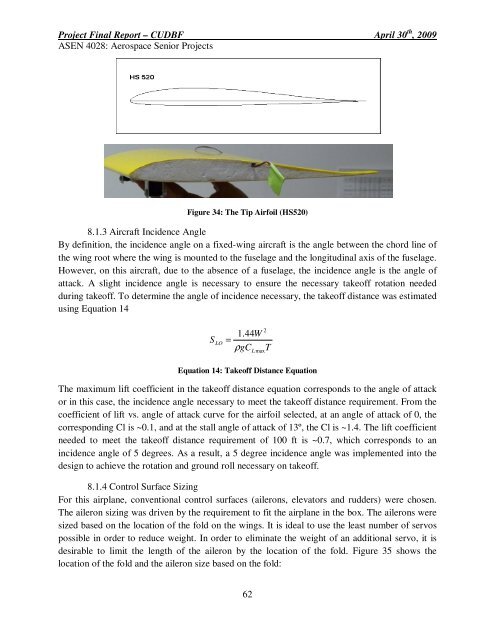
Figure 34: The Tip Airfoil (HS520)<br />
8.1.3 Aircraft Incidence Angle<br />
By definition, the incidence angle on a fixed-wing aircraft is the angle between the chord line of<br />
the wing root where the wing is mounted to the fuselage and the longitudinal axis of the fuselage.<br />
However, on this aircraft, due to the absence of a fuselage, the incidence angle is the angle of<br />
attack. A slight incidence angle is necessary to ensure the necessary takeoff rotation needed<br />
during takeoff. To determine the angle of incidence necessary, the takeoff distance was estimated<br />
using Equation 14<br />
S<br />
LO<br />
2<br />
1.44W<br />
=<br />
ρgC<br />
T<br />
L max<br />
Equation 14: Takeoff Distance Equation<br />
The maximum lift coefficient in the takeoff distance equation corresponds to the angle of attack<br />
or in this case, the incidence angle necessary to meet the takeoff distance requirement. From the<br />
coefficient of lift vs. angle of attack curve for the airfoil selected, at an angle of attack of 0, the<br />
corresponding Cl is ~0.1, and at the stall angle of attack of 13º, the Cl is ~1.4. The lift coefficient<br />
needed to meet the takeoff distance requirement of 100 ft is ~0.7, which corresponds to an<br />
incidence angle of 5 degrees. As a result, a 5 degree incidence angle was implemented into the<br />
design to achieve the rotation and ground roll necessary on takeoff.<br />
8.1.4 Control Surface Sizing<br />
For this airplane, conventional control surfaces (ailerons, elevators and rudders) were chosen.<br />
The aileron sizing was driven by the requirement to fit the airplane in the box. The ailerons were<br />
sized based on the location of the fold on the wings. It is ideal to use the least number of servos<br />
possible in order to reduce weight. In order to eliminate the weight of an additional servo, it is<br />
desirable to limit the length of the aileron by the location of the fold. Figure 35 shows the<br />
location of the fold and the aileron size based on the fold:<br />
62


