

PFR - Aerospace Engineering Sciences Senior Design Projects ...
PFR - Aerospace Engineering Sciences Senior Design Projects ...
PFR - Aerospace Engineering Sciences Senior Design Projects ...

Create successful ePaper yourself
Turn your PDF publications into a flip-book with our unique Google optimized e-Paper software.
Project Final Report – CUDBF April 30 th , 2009<br />
ASEN 4028: <strong>Aerospace</strong> <strong>Senior</strong> <strong>Projects</strong><br />
A simply supported beam was analyzed, fixed at one end with a load P applied at the free tip of<br />
the beam. From Vable, the critical load experienced by the beam (i.e. the maximum amount of<br />
force the column can take before it buckles) is known and seen in Equation 33. Simply<br />
rearranging the critical load equation, knowing the moment of inertia for a cylinder, the radius<br />
can be solved for as in Equation 34. The code is provided in Appendix I.<br />
Equation 33: Beam Buckling Critical Load<br />
Equation 34: Minimum Radius for the Buckling Case<br />
The analysis of these different beam cases under the same applied forces proved the deflection of<br />
the landing gear to be of the higher concern. Thus Equation 32 showed the minimum diameter<br />
for the Al 2024 material properties was 0.2 inches. In order to both add a safety factor while at<br />
the same time easing the manufacturing of the landing gear, the final selected landing gear<br />
diameter is the readily available 0.25 inch diameter Al 2024.<br />
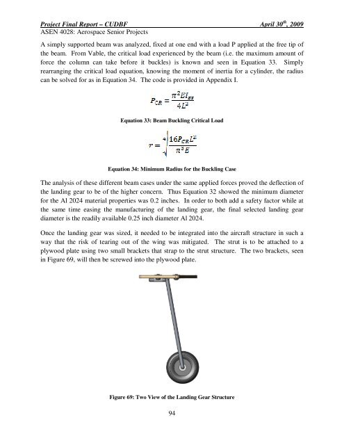
Once the landing gear was sized, it needed to be integrated into the aircraft structure in such a<br />
way that the risk of tearing out of the wing was mitigated. The strut is to be attached to a<br />
plywood plate using two small brackets that strap to the strut structure. The two brackets, seen<br />
in Figure 69, will then be screwed into the plywood plate.<br />
Figure 69: Two View of the Landing Gear Structure<br />
94


