

PFR - Aerospace Engineering Sciences Senior Design Projects ...
PFR - Aerospace Engineering Sciences Senior Design Projects ...
PFR - Aerospace Engineering Sciences Senior Design Projects ...

You also want an ePaper? Increase the reach of your titles
YUMPU automatically turns print PDFs into web optimized ePapers that Google loves.
Project Final Report – CUDBF April 30 th , 2009<br />
ASEN 4028: <strong>Aerospace</strong> <strong>Senior</strong> <strong>Projects</strong><br />
The hinge is connected to a long balsa spar that runs through most of the length of the wingtip.<br />
This spar rigidly connects the wingtip to the main body, and distributes the load along the wing.<br />
It is screwed into the integral hinge and glued into the underside of the wingtip foam.<br />
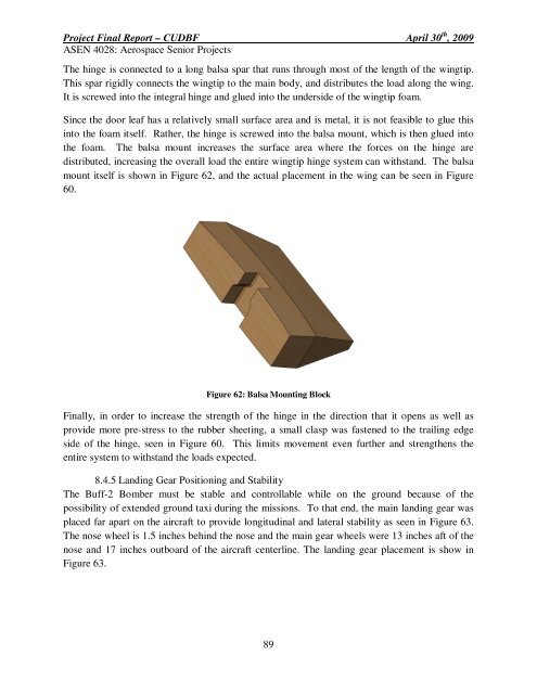
Since the door leaf has a relatively small surface area and is metal, it is not feasible to glue this<br />
into the foam itself. Rather, the hinge is screwed into the balsa mount, which is then glued into<br />
the foam. The balsa mount increases the surface area where the forces on the hinge are<br />
distributed, increasing the overall load the entire wingtip hinge system can withstand. The balsa<br />
mount itself is shown in Figure 62, and the actual placement in the wing can be seen in Figure<br />
60.<br />
Figure 62: Balsa Mounting Block<br />
Finally, in order to increase the strength of the hinge in the direction that it opens as well as<br />
provide more pre-stress to the rubber sheeting, a small clasp was fastened to the trailing edge<br />
side of the hinge, seen in Figure 60. This limits movement even further and strengthens the<br />
entire system to withstand the loads expected.<br />
8.4.5 Landing Gear Positioning and Stability<br />
The Buff-2 Bomber must be stable and controllable while on the ground because of the<br />
possibility of extended ground taxi during the missions. To that end, the main landing gear was<br />
placed far apart on the aircraft to provide longitudinal and lateral stability as seen in Figure 63.<br />
The nose wheel is 1.5 inches behind the nose and the main gear wheels were 13 inches aft of the<br />
nose and 17 inches outboard of the aircraft centerline. The landing gear placement is show in<br />
Figure 63.<br />
89


