Th`ese Marouan BOUALI - Sites personnels de TELECOM ParisTech
Th`ese Marouan BOUALI - Sites personnels de TELECOM ParisTech
Th`ese Marouan BOUALI - Sites personnels de TELECOM ParisTech

Create successful ePaper yourself
Turn your PDF publications into a flip-book with our unique Google optimized e-Paper software.
65<br />
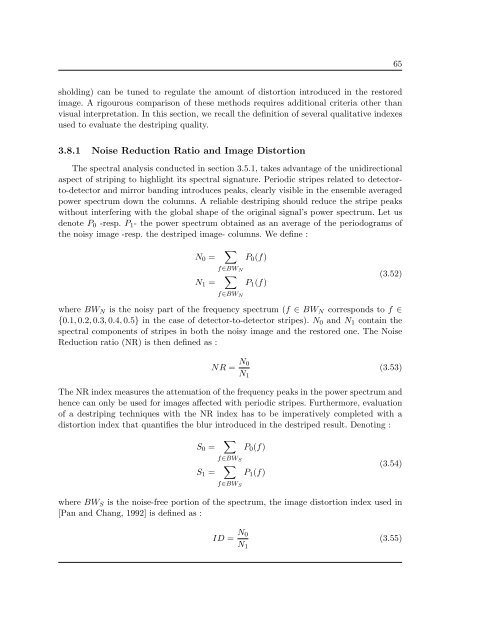
sholding) can be tuned to regulate the amount of distortion introduced in the restored<br />
image. A rigourous comparison of these methods requires additional criteria other than<br />
visual interpretation. In this section, we recall the <strong>de</strong>finition of several qualitative in<strong>de</strong>xes<br />
used to evaluate the <strong>de</strong>striping quality.<br />
3.8.1 Noise Reduction Ratio and Image Distortion<br />
The spectral analysis conducted in section 3.5.1, takes advantage of the unidirectional<br />
aspect of striping to highlight its spectral signature. Periodic stripes related to <strong>de</strong>tectorto-<strong>de</strong>tector<br />
and mirror banding introduces peaks, clearly visible in the ensemble averaged<br />
power spectrum down the columns. A reliable <strong>de</strong>striping should reduce the stripe peaks<br />
without interfering with the global shape of the original signal’s power spectrum. Let us<br />
<strong>de</strong>note P 0 -resp. P 1 - the power spectrum obtained as an average of the periodograms of<br />
the noisy image -resp. the <strong>de</strong>striped image- columns. We <strong>de</strong>fine :<br />
N 0 =<br />
∑<br />
P 0 (f)<br />
f∈BW N<br />
N 1 =<br />
∑<br />
P 1 (f)<br />
f∈BW N<br />
(3.52)<br />
where BW N is the noisy part of the frequency spectrum (f ∈ BW N corresponds to f ∈<br />
{0.1, 0.2, 0.3, 0.4, 0.5} in the case of <strong>de</strong>tector-to-<strong>de</strong>tector stripes). N 0 and N 1 contain the<br />
spectral components of stripes in both the noisy image and the restored one. The Noise<br />
Reduction ratio (NR) is then <strong>de</strong>fined as :<br />
NR = N 0<br />
N 1<br />
(3.53)<br />
The NR in<strong>de</strong>x measures the attenuation of the frequency peaks in the power spectrum and<br />
hence can only be used for images affected with periodic stripes. Furthermore, evaluation<br />
of a <strong>de</strong>striping techniques with the NR in<strong>de</strong>x has to be imperatively completed with a<br />
distortion in<strong>de</strong>x that quantifies the blur introduced in the <strong>de</strong>striped result. Denoting :<br />
S 0 =<br />
∑<br />
P 0 (f)<br />
f∈BW S<br />
S 1 =<br />
∑<br />
P 1 (f)<br />
f∈BW S<br />
(3.54)<br />
where BW S is the noise-free portion of the spectrum, the image distortion in<strong>de</strong>x used in<br />
[Pan and Chang, 1992] is <strong>de</strong>fined as :<br />
ID = N 0<br />
N 1<br />
(3.55)