Create successful ePaper yourself
Turn your PDF publications into a flip-book with our unique Google optimized e-Paper software.
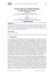
force is dropped, all elements unload, and the<br />
displacement is reduced. Once the yielded hinge<br />
reaches the Point D force level, the pushover<br />
force (base shear) is again increased and the<br />
displacement begins to increase again. This<br />
behavior is apparent when displaying the<br />
deformed shapes and force diagrams (moment,<br />
shear, etc.) for each step of the pushover, when<br />
viewing a video created for the pushover, and<br />
when displaying the force-displacement plot of<br />
the pushover.<br />
Force<br />
A<br />
B<br />
IO<br />
C<br />
LS<br />
CP<br />
D<br />
Displacement<br />
E<br />
17. Click the Show Undeformed Shape button to clear the display of deformed shape for<br />
the pushover.<br />
18. Click the Set Elements button on the main toolbar (or select Set Elements… from the<br />
View menu). This displays the Set Elements Dialog box.<br />
19. In this dialog box:<br />
• Uncheck the Shrink Elements box in the options area (if it is checked).<br />
• Click the OK button.<br />
This completes the review of the pushover deformed shape and the sequence of pushover hinge<br />
formation. You may want to step through the deformed shapes for the other pushover load cases<br />
before proceeding on to the next step.<br />
<strong>SAP2000</strong> <strong>Web</strong> <strong>Tutorial</strong> 1 109