- Page 1 and 2:
Electromagnetic Testing Study Guide
- Page 3 and 4:
E&P Applications Charlie Chong/ Fio
- Page 5 and 6:
Charlie Chong/ Fion Zhang
- Page 7 and 8:
乱 七 八 糟 - 随 看 随 记 C
- Page 9 and 10:
Charlie Chong/ Fion Zhang
- Page 11 and 12:
Charlie Chong/ Fion Zhang http://ww
- Page 13 and 14:
IVONA TTS Capable. Charlie Chong/ F
- Page 15 and 16:
EDDY CURRENT an Overview Descriptio
- Page 17 and 18:
Tangential Probe Charlie Chong/ Fio
- Page 19 and 20:
Electromagnetic Testing Advantages
- Page 21 and 22:
Factors Affecting Eddy Current Resp
- Page 23 and 24:
from this it can be seen that depth
- Page 25 and 26:
http://www.eng.morgan.edu/~hubert/I
- Page 27 and 28:
Robotic Charlie Chong/ Fion Zhang
- Page 29 and 30:
Measurement Techniques (EN!) a) Abs
- Page 31 and 32:
Figure 1.1 Arago’s Experiment Cha
- Page 33 and 34:
Oersted discovered the presence of
- Page 35 and 36:
Figure 1.3: Induced current electro
- Page 37 and 38:
Charlie Chong/ Fion Zhang http://en
- Page 39 and 40:
Charlie Chong/ Fion Zhang http://en
- Page 41 and 42:
The law of physics describing the p
- Page 43 and 44:
Charlie Chong/ Fion Zhang http://hy
- Page 45 and 46:
Magnetic Force The magnetic field B
- Page 47 and 48:
Generation of Eddy Currents When a
- Page 49 and 50:
Factors Affecting Inductance There
- Page 51 and 52:
COIL LENGTH: All other factors bein
- Page 53 and 54:
Coil Inductance L An approximation
- Page 55 and 56:
Note the direction of the primary c
- Page 57 and 58:
Generation of Eddy Current With a p
- Page 59 and 60:
Charlie Chong/ Fion Zhang Permeabil
- Page 61 and 62:
A Dual Variable inductors Figure 1:
- Page 63 and 64:
Figure 3: Here is another inductor
- Page 65 and 66:
Figure 4: The two inductors on this
- Page 67 and 68:
Grundig radio satellit 750 ■ http
- Page 69 and 70:
Figure 1.7: Phasor Diagram of Coil
- Page 71 and 72:
Current Density The distribution of
- Page 73 and 74:
Figure 1.8: Relative eddy current d
- Page 75 and 76:
Relative Magnetic Permeability Perm
- Page 77 and 78:
It should be observed at this point
- Page 79 and 80:
δ = (π x 100 x 10 3 x 4 x π x 0.
- Page 81 and 82:
Using 1.35 mm as depth x from surfa
- Page 83 and 84:
Standard Depth for Different Conduc
- Page 85 and 86:
Current (?) Lagging Voltage lagging
- Page 87 and 88:
σº∙πμ■δ∝∞ωΩθ√ρβ
- Page 89 and 90:
Figure 1.9 should be used as a rela
- Page 91 and 92:
Figure 1.8: Relative eddy current d
- Page 93 and 94:
Q.1.1 Generation of eddy currents d
- Page 95 and 96:
Q.1.5 Eddy current generated a test
- Page 97 and 98:
Q.1.9 Refer to Figure1.9 using exam
- Page 99 and 100:
Chapter 2 The Coil Arrangements Cha
- Page 101 and 102:
Probe coils and probe coil forms ca
- Page 103 and 104:
Encircling Coils Encircling coil, o
- Page 105 and 106:
Discussion Subject; Encircling Coil
- Page 107 and 108:
Bobbin Coils Bobbin coil, inside di
- Page 109 and 110:
Figure 2.5: Test coil configuration
- Page 111 and 112:
Differential coils Differential coi
- Page 113 and 114:
Figure 2.6: External reference diff
- Page 115 and 116:
Figure 2.7: Hybrid coil (through tr
- Page 117 and 118:
Additional Coil Characteristics Coi
- Page 119 and 120:
Q.2.1 Differential coils are usuall
- Page 121 and 122:
Q.2.6 An absolute coil measurement
- Page 123 and 124:
The Answers Charlie Chong/ Fion Zha
- Page 125 and 126:
As discussed earlier test coil desi
- Page 127 and 128:
Demonstration model of a moving iro
- Page 129 and 130:
Thus, the resistance of a 10 ft len
- Page 131 and 132:
SPECIFIC RESISTANCE OR RESISTIVITY
- Page 133 and 134:
Problem: What is the resistance of
- Page 135 and 136:
The inductance of a multilayer air
- Page 137 and 138:
Example: A coil whose dimensions ar
- Page 139 and 140:
Example: Using the 32 μH coil calc
- Page 141 and 142:
Impedance To explain the addition o
- Page 143 and 144:
Maximum transfer of power is accomp
- Page 145 and 146:
Rectangular Notation Because reacta
- Page 147 and 148:
Vectors With Polar Notations. Stand
- Page 149 and 150:
Rectangular Notation - Prefix “j
- Page 151 and 152: Imaginary Component In “rectangul
- Page 153 and 154: Imaginary Charlie Chong/ Fion Zhang
- Page 155 and 156: To convert from rectangular to pola
- Page 157 and 158: More Reading on Polar & Rectangular
- Page 159 and 160: Eddy current coils with included im
- Page 161 and 162: Permeability and Shielding Effects
- Page 163 and 164: Another technique of shielding uses
- Page 165 and 166: Saturation Approach Another coil de
- Page 167 and 168: Figure 3.5: Magnetic bias probe Cha
- Page 169 and 170: Materials must be chemically compat
- Page 171 and 172: Q.3.1 A coil's resistance is determ
- Page 173 and 174: Q.3.7 The Q or merit of a coil is d
- Page 175 and 176: The Answers Charlie Chong/ Fion Zha
- Page 177 and 178: Jackfruit Tree Charlie Chong/ Fion
- Page 179 and 180: Electrical Conductivity σ In elect
- Page 181 and 182: As previously discussed, conductivi
- Page 183 and 184: Figure 4.1; Conductivity curve Char
- Page 185 and 186: The coil's inductive reactance is r
- Page 187 and 188: Effects of Heat Treatment on Conduc
- Page 189 and 190: Permeability Permeability of any ma
- Page 191 and 192: When increases in the magnetizing f
- Page 193 and 194: Skin Effect Charlie Chong/ Fion Zha
- Page 195 and 196: Discussion Subject: Response to the
- Page 197 and 198: Lift Off Electromagnetic coupling b
- Page 199 and 200: Fill factor will always be a number
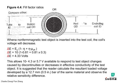
- Page 201: Figure 4.4: Fill factor ratios When
- Page 205 and 206: Figure 1.8 is again useful to illus
- Page 207 and 208: Signal-to-Noise Ratio Signal-to-noi
- Page 209 and 210: The Answers Charlie Chong/ Fion Zha
- Page 211 and 212: Q.4.4 A (?) prime factor affecting
- Page 213 and 214: Q.4.10 Temperature changes, vibrati
- Page 215 and 216: Test Frequencies It is the responsi
- Page 217 and 218: Single Frequency Systems Unfortunat
- Page 219 and 220: Eddy Current Density Since the sens
- Page 221 and 222: Applicable Scenario Eddy Current De
- Page 223 and 224: Standard Depth δ Formula The depth
- Page 225 and 226: Example 1: As an example of how thi
- Page 227 and 228: Frequency Selection - Ferromagnetic
- Page 229 and 230: A frequency can always selected to
- Page 231 and 232: Figure 5.1(a) shows the effect on p
- Page 233 and 234: Figure 5.1: Effects of frequency ch
- Page 235 and 236: Figure 5.2: Normalized impedance di
- Page 237 and 238: Figure 5.3: Impedance variations ca
- Page 239 and 240: Figure 5.4: Impedance variations ca
- Page 241 and 242: Multiparameter Techniques It become
- Page 243 and 244: Multiparameter Techniques - Multipl
- Page 245 and 246: First, a frequency is selected to g
- Page 247 and 248: More Reading on Characteristic Para
- Page 249 and 250: Figure 1: Eddy Current Testing Char
- Page 251 and 252: Figure 2: Types of Probes Charlie C
- Page 253 and 254:
Surface (Pancake) Probes Surface pr
- Page 255 and 256:
Encircling Probes Encircling probes
- Page 257 and 258:
Design of eddy current probes In mo
- Page 259 and 260:
In brief, probe design is usually d
- Page 261 and 262:
Analytical Approach (Pc & f g ) Ana
- Page 263 and 264:
RECENT TRENDS IN EDDY CURRENT PROBE
- Page 265 and 266:
Pressurized Heavy Water Reactors (P
- Page 267 and 268:
The Answers Charlie Chong/ Fion Zha
- Page 269 and 270:
Q.5.4 Calculate the limit frequency
- Page 271 and 272:
Q.5.7 Primary resistance is subtrac
- Page 273 and 274:
Q5.9 A 25% deep crack open to the n
- Page 275 and 276:
Chapter 6 Instrument Systems Charli
- Page 277 and 278:
Eddy Current Instrumentation Most o
- Page 279 and 280:
Figure 6.1: Internal functions of t
- Page 281 and 282:
Chernobyl Nuclear Power Plant Charl
- Page 283 and 284:
Figure 6.2: Four types of simple ed
- Page 285 and 286:
Figure 6.2(b) shows an impedance br
- Page 287 and 288:
Figure 6.2(d) illustrates a balanci
- Page 289 and 290:
Eddy current testing - Signal Analy
- Page 291 and 292:
Impedance Testing With impedance ma
- Page 293 and 294:
Phase Analysis Testing - Vector Poi
- Page 295 and 296:
Phase Analysis Testing - Ellipse As
- Page 297 and 298:
Figure 6.4: Cathode ray tube displa
- Page 299 and 300:
Figure 6.5: Screen image of a linea
- Page 301 and 302:
Impedance Plane Testing - Mode of O
- Page 303 and 304:
Figure 6.6: Null balance instrument
- Page 305 and 306:
Figure 6.7: Typical surface riding
- Page 307 and 308:
For deep subsurface crack detection
- Page 309 and 310:
Multiple circuits are used througho
- Page 311 and 312:
This type of digital instrumentatio
- Page 313 and 314:
Figure 6.1: Internal functions of t
- Page 315 and 316:
Read Out Mechanisms - Audio Alarms
- Page 317 and 318:
An qualitative meter response could
- Page 319 and 320:
Figure 6.13: A qualitative analog m
- Page 321 and 322:
Read Out Mechanisms - Cathode Ray T
- Page 323 and 324:
Figure 6.14: Numerical readouts/dig
- Page 325 and 326:
Read Out Mechanisms - Computer Eddy
- Page 327 and 328:
Figure 6.1: Internal functions of t
- Page 329 and 330:
Probe Delivery System Instead of mo
- Page 331 and 332:
Chapter 6 Review Questions Charlie
- Page 333 and 334:
Q.6.1 Signal preparation is usually
- Page 335 and 336:
Q.6.7 Amplitude gates provide a tec
- Page 337 and 338:
Chapter 7 Eddy Current Applications
- Page 339 and 340:
Discontinuity Detection The theoret
- Page 341 and 342:
Heat Exchanger Charlie Chong/ Fion
- Page 343 and 344:
Heat Exchanger Charlie Chong/ Fion
- Page 345 and 346:
Heat Exchanger Charlie Chong/ Fion
- Page 347 and 348:
Heat Exchanger Charlie Chong/ Fion
- Page 349 and 350:
Heat Exchanger TSP Charlie Chong/ F
- Page 351 and 352:
Heat Exchanger TSP Charlie Chong/ F
- Page 353 and 354:
Figure 7.2: Phase-to-depth calibrat
- Page 355 and 356:
The geometry of real discontinuitie
- Page 357 and 358:
Figure 7.5: A multifrequency applic
- Page 359 and 360:
Aerospace Applications Charlie Chon
- Page 361 and 362:
The reference specimen and its asso
- Page 363 and 364:
Dimensional Measurements Dimensiona
- Page 365 and 366:
Figure 7.6: A single frequency hard
- Page 367 and 368:
Conductivity Measurements Conductiv
- Page 369 and 370:
Alloy Sorting Alloy sorting can als
- Page 371 and 372:
In addition, it is advisable to hav
- Page 373 and 374:
Answers Charlie Chong/ Fion Zhang
- Page 375 and 376:
Q.7.4 Using multifrequency techniqu
- Page 377 and 378:
Q.7.7 Response to multilayer varyin
- Page 379 and 380:
Chapter 8 Other Electromagnetic Tec
- Page 381 and 382:
Some other technologies that have b
- Page 383 and 384:
Alternating current field measureme
- Page 385 and 386:
Figure 8.1 shows the basic principl
- Page 387 and 388:
ACFM Principle Charlie Chong/ Fion
- Page 389 and 390:
ACFM Z X Bx =magnetic flux componen
- Page 391 and 392:
Alternating current field measureme
- Page 393 and 394:
The technique in its simplest form
- Page 395 and 396:
Alternating current field measureme
- Page 397 and 398:
Magnetic Flux Leakage Testing Prima
- Page 399 and 400:
Figure 8.2: Equipment for magnetic
- Page 401 and 402:
Magnetic Flux Leakage Testing Charl
- Page 403 and 404:
The most commonly used inservice in
- Page 405 and 406:
Magnetic Saturation Charlie Chong/
- Page 407 and 408:
The magnetization curve is not retr
- Page 409 and 410:
Magnetic Flux Leakage Testing Charl
- Page 411 and 412:
Magnetic Flux Leakage The basic pri
- Page 413 and 414:
Magnetic Flux Leakage Magnetic Flux
- Page 415 and 416:
Special hybrid (driver/pick up) coi
- Page 417 and 418:
At distances in excess of two tube
- Page 419 and 420:
Figure 8.4: Remote field testing en
- Page 421 and 422:
Remote-Field Energy Zones - in remo
- Page 423 and 424:
Remote-Field Zone Transition Zone C
- Page 425 and 426:
RFT - Flux distribution in pipe (a)
- Page 427 and 428:
Remote Field Zone - The third defin
- Page 429 and 430:
Amplitude (voltage) - The remote fi
- Page 431 and 432:
RFT Charlie Chong/ Fion Zhang http:
- Page 433 and 434:
The Remote Field Technique is an el
- Page 435 and 436:
Remote Field Eddy Current Technique
- Page 437 and 438:
More Reading: RFT Remote Field Test
- Page 439 and 440:
These eddy currents, in turn, produ
- Page 441 and 442:
The Zones Direct Couple Zone The re
- Page 443 and 444:
RFT Probes Probes for inspection of
- Page 445 and 446:
RFT Signal Interpretation The signa
- Page 447 and 448:
RFT Reference Standards Reference s
- Page 449 and 450:
Answers Charlie Chong/ Fion Zhang
- Page 451 and 452:
Q.8.4 A generally accepted definiti
- Page 453 and 454:
Q.8.8 The region of intense electro
- Page 455 and 456:
Chapter 9 Eddy Current Procedures,
- Page 457 and 458:
American Society for Testing and Ma
- Page 459 and 460:
Military Standard The United States
- Page 461 and 462:
EDDY CURRENT INSPECTION OF NONFERRO
- Page 463 and 464:
. Probe positioning and feeding sha
- Page 465 and 466:
3. Tube Inspection General (Refer t
- Page 467 and 468:
F. INSPECTION RESULTS AND DOCUMENTA
- Page 469 and 470:
G. REFERENCES The following documen
- Page 471 and 472:
Answers Charlie Chong/ Fion Zhang
- Page 473 and 474:
Q.9.4 Military Standards are design
- Page 475 and 476:
Q.9.10 The system in QA3 is calibra
- Page 477 and 478:
More Reading http://www.allaboutcir
- Page 479 and 480:
Discussion Subject: discuss on the
- Page 481 and 482:
Charlie Chong/ Fion Zhang
- Page 483 and 484:
Inspection from the Tube OD Most AS
- Page 485 and 486:
Approximately 25 years ago, the AST
- Page 487 and 488:
One additional advantage of OD ECT
- Page 489 and 490:
The baseline eddy current test The
- Page 491 and 492:
There is no standard accept/reject
- Page 493 and 494:
Pulsed Eddy Currents Systems Charli
- Page 495 and 496:
Although still an active research f
- Page 497 and 498:
LOI (Lift-Off point of Intersection
- Page 499 and 500:
Gap Point : Similar to the LOI, the
- Page 501 and 502:
Driving Coil Charlie Chong/ Fion Zh
- Page 503 and 504:
Hall effect sensors In opposition t
- Page 505 and 506:
Crack Detection using Pulsed Eddy C
- Page 507 and 508:
Fig. 1 (a) ARMANDA - Automated scan
- Page 509 and 510:
Fig. 2. Images of the Eddy current
- Page 511 and 512:
Reading 2: 4.9.2.3 Pulsed Eddy Curr
- Page 513 and 514:
Good Luck Charlie Chong/ Fion Zhang