- Page 1 and 2:
CERN/SPSC 2000-028 SPSC/P318 LNGS P
- Page 3 and 4:
N. Bruski, S. Buontempo, F. Carbona
- Page 5 and 6:
Contents 1 Introduction 5 1.1 Physi
- Page 7 and 8:
6.7.1 Multiple scattering analysis
- Page 9 and 10:
1 Introduction In this document we
- Page 11 and 12:
eactor experiments (KAMLAND [22], B
- Page 13 and 14:
difference being the nature of the
- Page 15 and 16:
The total energy of electrons and
- Page 17 and 18:
through the decay topology and its
- Page 19 and 20:
Figure 6: Simulated ν τ event wit
- Page 21 and 22:
particles above 10 MeV . One can se
- Page 23 and 24:
vertex position as predicted by the
- Page 25 and 26:
• stability and maintenance: no p
- Page 27 and 28:
Figure 11: Illustration of the vari
- Page 29 and 30:
Table 3: Expected numbers of τ and
- Page 31 and 32:
3 The CNGS neutrino beam 3.1 The be
- Page 33 and 34:
per year of operation because the S
- Page 35 and 36:
ν µ at GS (p.o.t. GeV m 2 ) -1 10
- Page 37 and 38:
Figure 19: Generated (continuous li
- Page 39 and 40:
Emulsion Film + 56 (Lead + Emulsion
- Page 41 and 42:
The mechanical properties of the fi
- Page 43 and 44:
Figure 24: Film thickness distribut
- Page 45 and 46:
contact at different temperature an
- Page 47 and 48:
Figure 27: Photograph of a minimum
- Page 49 and 50: entry : 85 RMS: 0.060 15 10 5 0 0 d
- Page 51 and 52: [micron] 2 1 0 -1 -2 [micron] 2 1 0
- Page 53 and 54: een searching for old emulsion plat
- Page 55 and 56: Figure 33: Thickness distribution f
- Page 57 and 58: Figure 35: RMS distribution of 472
- Page 59 and 60: Figure 37: Wall support structure.
- Page 61 and 62: ensures a well defined brick positi
- Page 63 and 64: Figure 41: Detail of the brick mani
- Page 65 and 66: The strips are 6.7 m long, 2.6 cm w
- Page 67 and 68: the effective maximal length (for p
- Page 69 and 70: Table 7: Characteristics of the 64-
- Page 71 and 72: photomultiplier to be tested diaphr
- Page 73 and 74: modate from 512 up to 5180 fibres.
- Page 75 and 76: The fast shaper has a high gain in
- Page 77 and 78: The Ethernet capable device provide
- Page 79 and 80: R&D already performed by the MINOS
- Page 81 and 82: Figure 54: Isometric view of the di
- Page 83 and 84: Figure 56: Magnetic field distribut
- Page 85 and 86: RPC layout 8.00 m 8.75 m Figure 58:
- Page 87 and 88: formance, it is presently foreseen
- Page 89 and 90: Figure 61: Drift plane arrangement
- Page 91 and 92: Figure 63: Schematic view of a XPC
- Page 93 and 94: Figure 64: Acceleration spectrum fo
- Page 95 and 96: Figure 65: The OPERA detector shown
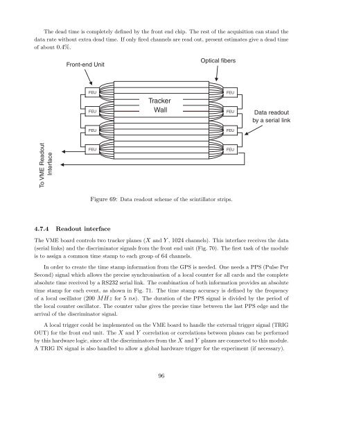
- Page 97 and 98: Table 9: Number of electronic chann
- Page 99: Adjustable gain Channel 0 Sample &
- Page 103 and 104: Super Module 1 Super Module 2 Super
- Page 105 and 106: 5 Analysis of the electronic detect
- Page 107 and 108: Track segments on both the emulsion
- Page 109 and 110: 5.5 Brick finding efficiency The se
- Page 111 and 112: Wall finding efficiency 1 0.95 0.9
- Page 113 and 114: The worst case leading to the lowes
- Page 115 and 116: electromagnetic showering events an
- Page 117 and 118: Studies on the strategies have star
- Page 119 and 120: which may enter in such a compariso
- Page 121 and 122: Figure 84: The total brick finding
- Page 123 and 124: Figure 86: Charge determination of
- Page 125 and 126: Figure 89: Muon momentum resolution
- Page 127 and 128: Figure 91: Muon momentum resolution
- Page 129 and 130: Reconstructed Pion Energy N Analog
- Page 131 and 132: Figure 98: The difference between r
- Page 133 and 134: By using the above running modes of
- Page 135 and 136: µm EXP.: DONUT 3039/01910 MOD.:ECC
- Page 137 and 138: emulsion film plastic foils and edg
- Page 139 and 140: 200micron base 50micron emulsion la
- Page 141 and 142: Figure 106: Tracking efficiency of
- Page 143 and 144: a base track on film 2 a penetratin
- Page 145 and 146: Long decays, defined as a decay top
- Page 147 and 148: more than 60 views/s recognising al
- Page 149 and 150: Table 12: Basic numbers used to des
- Page 151 and 152:
an area that one S-UTS can process
- Page 153 and 154:
unit cell L=1300micron Pb plate ( 1
- Page 155 and 156:
We recall that the intrinsic positi
- Page 157 and 158:
Figure 116: The top histograms show
- Page 159 and 160:
The error on θ S due to both the s
- Page 161 and 162:
Figure 120: Fraction of pions which
- Page 163 and 164:
#1 #2 #3 #4 #5 γ γ ∆θ 4= |θ 5
- Page 165 and 166:
Figure 124: Energy resolution for e
- Page 167 and 168:
Figure 126: Efficiency for γ’s t
- Page 169 and 170:
7 Physics performance 7.1 Electron
- Page 171 and 172:
7.2 Muon identification efficiency
- Page 173 and 174:
Table 13: Muon identification effic
- Page 175 and 176:
Table 14: Brick finding efficiency
- Page 177 and 178:
The second result is obtained from
- Page 179 and 180:
Figure 134: Brick-to-brick connecti
- Page 181 and 182:
Figure 136: Distribution of τ deca
- Page 183 and 184:
For long decays the overall efficie
- Page 185 and 186:
The φ angle is expected to peak at
- Page 187 and 188:
Table 19: Summary of the kinematica
- Page 189 and 190:
known. Because of these uncertainti
- Page 191 and 192:
Table 21: Expected charm background
- Page 193 and 194:
π− e+ γ e- e+ e- γ π− Figur
- Page 195 and 196:
Table 24: Estimates of the rate of
- Page 197 and 198:
Table 27: Expected numbers of τ an
- Page 199 and 200:
Table 28: Sensitivity at the 90% CL
- Page 201 and 202:
7.6 Determination of the oscillatio
- Page 203 and 204:
measurement of the ratio between ν
- Page 205 and 206:
Table 30: Neural network recognitio
- Page 207 and 208:
(mrad) 0.04 0.02 0 -0.02 -0.04 10 2
- Page 209 and 210:
Table 31: Radioactivity measurement
- Page 211 and 212:
ick. There is approximately a facto
- Page 213 and 214:
Figure 152: A typical PMT response
- Page 215 and 216:
1m π, µ 15 GeV/c mini-walls 1.6 m
- Page 217 and 218:
Electrons 1GeV/c 20mm Pb Number of
- Page 219 and 220:
tube. An Image Intensifier (II) by
- Page 221 and 222:
1 0 0 l = 1 1 .8 m N, p.e. 1 0 1 0
- Page 223 and 224:
HPD’s pixels (Fig. 162). The cook
- Page 225 and 226:
A complete system has been designed
- Page 227 and 228:
The acquisition system (VA-DAQ) use
- Page 229 and 230:
The upstream tracker T 1-3 between
- Page 231 and 232:
Figure 168: Distributions of the ap
- Page 233 and 234:
Figure 169: Example of a large-angl
- Page 235 and 236:
multiple scattering, given the smal
- Page 237 and 238:
9.1.3 Wall support structures An al
- Page 239 and 240:
Nevertheless, the possibility to us
- Page 241 and 242:
Figure 174: (a) 3D view of the spec
- Page 243 and 244:
9 p.e. and 6.9 p.e. at a distance f
- Page 245 and 246:
Figure 176: Neutrino induced charm
- Page 247 and 248:
A test programme for emulsion brick
- Page 249 and 250:
The space requirements in the exper
- Page 251 and 252:
advance. The sets of scintillator s
- Page 253 and 254:
Task Name Start Finish Study of mai
- Page 255 and 256:
11 Experimental infrastructure 11.1
- Page 257 and 258:
After the exposure to cosmic rays,
- Page 259 and 260:
on the size of these stations. A co
- Page 261 and 262:
Table 38: Expected contributions to
- Page 263 and 264:
the developed emulsions and to stan
- Page 265 and 266:
As the sensitivity is not limited b
- Page 267 and 268:
[26] M. Apollonio et al., Phys. Let
- Page 269:
[89] http : //tosca.web.cern.ch/T O