Experiment Proposal - opera - Infn
Experiment Proposal - opera - Infn
Experiment Proposal - opera - Infn

You also want an ePaper? Increase the reach of your titles
YUMPU automatically turns print PDFs into web optimized ePapers that Google loves.
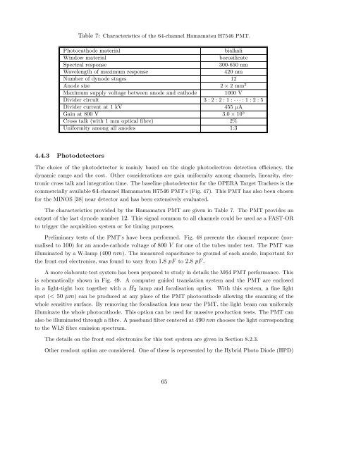
Table 7: Characteristics of the 64-channel Hamamatsu H7546 PMT.<br />
Photocathode material<br />
bialkali<br />
Window material<br />
borosilicate<br />
Spectral response<br />
300-650 nm<br />
Wavelength of maximum response<br />
420 nm<br />
Number of dynode stages 12<br />
Anode size 2 × 2mm 2<br />
Maximum supply voltage between anode and cathode 1000 V<br />
Divider circuit 3:2:2:1:···:1:2:5<br />
Divider current at 1 kV 455 µA<br />
Gain at 800 V 3.0 × 10 5<br />
Cross talk (with 1 mm optical fibre) 2%<br />
Uniformity among all anodes 1:3<br />
4.4.3 Photodetectors<br />
The choice of the photodetector is mainly based on the single photoelectron detection efficiency, the<br />
dynamic range and the cost. Other considerations are gain uniformity among channels, linearity, electronic<br />
cross talk and integration time. The baseline photodetector for the OPERA Target Trackers is the<br />
commercially available 64-channel Hamamatsu H7546 PMT’s (Fig. 47). This PMT has also been chosen<br />
for the MINOS [38] near detector and has been extensively evaluated.<br />
The characteristics provided by the Hamamatsu PMT are given in Table 7. The PMT provides an<br />
output of the last dynode number 12. This signal common to all channels could be used as a FAST-OR<br />
to trigger the acquisition system or for timing purposes.<br />
Preliminary tests of the PMT’s have been performed. Fig. 48 presents the channel response (normalised<br />
to 100) for an anode-cathode voltage of 800 V for one of the tubes under test. The PMT was<br />
illuminated by a W-lamp (400 nm). The measured capacitance to ground of each anode, important for<br />
the front end electronics, was found to vary from 1.8 pF to 2.8 pF .<br />
A more elaborate test system has been prepared to study in details the M64 PMT performance. This<br />
is schematically shown in Fig. 49. A computer guided translation system and the PMT are enclosed<br />
in a light-tight box together with a H 2 lamp and focalisation optics. With this system, a fine light<br />
spot (< 50 µm) can be produced at any place of the PMT photocathode allowing the scanning of the<br />
whole sensitive surface. By removing the focalisation lens near the PMT, the light beam can uniformly<br />
illuminate the whole photocathode. This option can be used for massive production tests. The PMT can<br />
also be illuminated through a fibre. A passband filter centered at 490 nm chooses the light corresponding<br />
to the WLS fibre emission spectrum.<br />
The details on the front end electronics for this test system are given in Section 8.2.3.<br />
Other readout option are considered. One of these is represented by the Hybrid Photo Diode (HPD)<br />
65