Experiment Proposal - opera - Infn
Experiment Proposal - opera - Infn
Experiment Proposal - opera - Infn

Create successful ePaper yourself
Turn your PDF publications into a flip-book with our unique Google optimized e-Paper software.
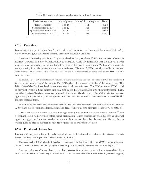
Table 9: Number of electronic channels in each main detector.<br />
Electronic detector Nb. of planes Nb. of channels/plane Total<br />
Target Trackers 3 × 48 512 73728<br />
Spectrometer RPC’s 3 × 22 560 36960<br />
Spectrometer drift tubes 3 × 6 768 13824<br />
Spectrometer XPC’s 3 × 2 790 4740<br />
4.7.2 Data flow<br />
To evaluate the expected data flow from the electronic detectors, we have considered a suitable safety<br />
factor, accounting for the largest possible number of electronic channels.<br />
A maximum counting rate induced by natural radioactivity of about 10 Hz per electronic channel is<br />
assumed. Detector and electronic noise have to be added. Using the Hamamatsu 64-channel PMT with<br />
a threshold corresponding to 1/3 photoelectron, a noise frequency lower than 5 Hz has been measured,<br />
mainly coming from the photocathode thermoemission. The use of HPD’s for the scintillator readout<br />
could increase the electronic noise by at least one order of magnitude as compared to the PMT for the<br />
same threshold.<br />
Taking into account possible noisy elements a mean electronic noise of the order of 50 Hz is considered<br />
for the scintillator strips of the target. For RPC’s the noise is assumed to be of the same order. The<br />
drift tubes of the Precision Trackers require an external time reference. The TDC common STOP could<br />
be provided (within a time shorter than 512 ns) by the RPC’s associated with the spectrometer. Thus,<br />
since the Precision Trackers do not participate in the trigger, the electronic noise of this detector does not<br />
significantly disturb the acquisition system. For the data flow evaluation an electronic noise of 50 Hz<br />
has also been assumed.<br />
Table 9 gives the number of electronic channels for the three detectors. For each detected hit, at most<br />
12 byte are stored (channel address, signal and time). The total rate amounts to about 90 Mbyte/s.<br />
If the final electronic noise rate would be significantly higher, fast time correlations between X and<br />
Y channels could be performed before signal digitization. These correlations could be used as external<br />
signal to trigger the frond end readout cards and thus, reduce the noise. In any case, the acquisition<br />
system must be able to support at least three times the above referred to rate.<br />
4.7.3 Front end electronics<br />
This part of the electronics is the only one which has to be adapted to each specific detector. In this<br />
Section, we describe in particular the scintillator readout.<br />
The front end unit includes the following components: the front end chip, the ADC’s, the local trigger,<br />
the serial link controller and the programmable chip. Its schematic diagram is shown in Fig. 67.<br />
One can make use of boxes close to the photodetector from where the data flow is transmitted by a<br />
serial link. The discriminator signal is also sent to the readout interface. Other signals (external trigger,<br />
93