LR-24 Electrofisher - Field Environmental Instruments
LR-24 Electrofisher - Field Environmental Instruments
LR-24 Electrofisher - Field Environmental Instruments

You also want an ePaper? Increase the reach of your titles
YUMPU automatically turns print PDFs into web optimized ePapers that Google loves.
SET UP & OPERATION<br />
USER'S MANUAL<br />
Set up and Operation<br />
Make sure the Electrode ring is clean and shiny. A cloudy dull-gray<br />
Electrode ring will reduce catch per unit effort and will increase<br />
the fish injury rate. Initial set up of voltage, frequency, duty cycle<br />
and waveform should be done outside of the sample area to avoid<br />
influencing the statistics.<br />
Basic Set up of the <strong>LR</strong>-<strong>24</strong>:<br />
1. Make sure the power switch on the top of the <strong>LR</strong>-<strong>24</strong> is in the<br />
OFF position (pressed DOWN).<br />
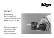
2. Attach the anode and cathode to their output connectors. Attach<br />
the smaller connector on the anode cable to the control connector<br />
of the <strong>LR</strong>-<strong>24</strong>. Determine desired position of anode<br />
and cathode cables. They can be set up to exit the battery<br />
compartment either from the bottom or the sides. To run the<br />
cables out the bottom of the battery compartment, place the<br />
cables in the molded troughs, then install the battery and attach<br />
the power cord. Place the strain reliefs of the anode and cathode<br />
cables in the slots at the bottom of the pack frame, adjust the<br />
battery cover so that it is on the inside of the molded guides of<br />
the pack frame. The cover must be correctly placed before the<br />
<strong>LR</strong>-<strong>24</strong> will operate (see figures 6.1 and 6.2). To run cables out<br />
the sides of the battery compartment, install the battery and<br />
attach the power cord of the <strong>LR</strong>-<strong>24</strong> then route the cables thru<br />
the slots in the sides of the battery compartment cover. Adjust<br />
the battery cover so that it is on the inside of the molded guides<br />
of the pack frame. The cover must be correctly placed before<br />
the <strong>LR</strong>-<strong>24</strong> will operate. Close the cover latches (see figures 6.3<br />
and 6.4).<br />
3. Put the <strong>LR</strong>-<strong>24</strong> on. Be sure to know the location of the quick<br />
release buckles for the backpack and unlatch the chest strap<br />
before entering or crossing the water (refer to Appendix E:<br />
Pack Adjustments for further instructions).<br />
4. Check with each crew member to be sure they know are ready<br />
to turn on the power.<br />
Fig. 6.1<br />
Cathode<br />
connector<br />
Fig. 6.2<br />
Fig. 6.3<br />
Fig. 6.4<br />
Control<br />
connector<br />
Anode<br />
connector<br />
www.smith-root.com<br />
25