ISU AT Command Reference
ISU AT Command Reference
ISU AT Command Reference

Create successful ePaper yourself
Turn your PDF publications into a flip-book with our unique Google optimized e-Paper software.
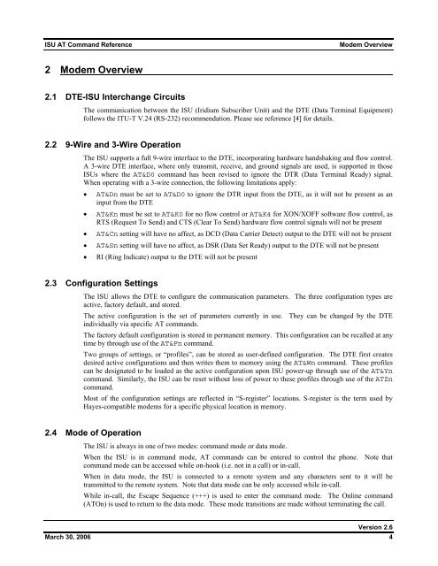
<strong>ISU</strong> <strong>AT</strong> <strong>Command</strong> <strong>Reference</strong>Modem Overview2 Modem Overview2.1 DTE-<strong>ISU</strong> Interchange CircuitsThe communication between the <strong>ISU</strong> (Iridium Subscriber Unit) and the DTE (Data Terminal Equipment)follows the ITU-T V.24 (RS-232) recommendation. Please see reference [4] for details.2.2 9-Wire and 3-Wire OperationThe <strong>ISU</strong> supports a full 9-wire interface to the DTE, incorporating hardware handshaking and flow control.A 3-wire DTE interface, where only transmit, receive, and ground signals are used, is supported in those<strong>ISU</strong>s where the <strong>AT</strong>&D0 command has been revised to ignore the DTR (Data Terminal Ready) signal.When operating with a 3-wire connection, the following limitations apply:• <strong>AT</strong>&Dn must be set to <strong>AT</strong>&D0 to ignore the DTR input from the DTE, as it will not be present as aninput from the DTE• <strong>AT</strong>&Kn must be set to <strong>AT</strong>&K0 for no flow control or <strong>AT</strong>&K4 for XON/XOFF software flow control, asRTS (Request To Send) and CTS (Clear To Send) hardware flow control signals will not be present• <strong>AT</strong>&Cn setting will have no affect, as DCD (Data Carrier Detect) output to the DTE will not be present• <strong>AT</strong>&Sn setting will have no affect, as DSR (Data Set Ready) output to the DTE will not be present• RI (Ring Indicate) output to the DTE will not be present2.3 Configuration SettingsThe <strong>ISU</strong> allows the DTE to configure the communication parameters. The three configuration types areactive, factory default, and stored.The active configuration is the set of parameters currently in use. They can be changed by the DTEindividually via specific <strong>AT</strong> commands.The factory default configuration is stored in permanent memory. This configuration can be recalled at anytime by through use of the <strong>AT</strong>&Fn command.Two groups of settings, or “profiles”, can be stored as user-defined configuration. The DTE first createsdesired active configurations and then writes them to memory using the <strong>AT</strong>&Wn command. These profilescan be designated to be loaded as the active configuration upon <strong>ISU</strong> power-up through use of the <strong>AT</strong>&Yncommand. Similarly, the <strong>ISU</strong> can be reset without loss of power to these profiles through use of the <strong>AT</strong>Zncommand.Most of the configuration settings are reflected in “S-register” locations. S-register is the term used byHayes-compatible modems for a specific physical location in memory.2.4 Mode of OperationThe <strong>ISU</strong> is always in one of two modes: command mode or data mode.When the <strong>ISU</strong> is in command mode, <strong>AT</strong> commands can be entered to control the phone. Note thatcommand mode can be accessed while on-hook (i.e. not in a call) or in-call.When in data mode, the <strong>ISU</strong> is connected to a remote system and any characters sent to it will betransmitted to the remote system. Note that data mode can be only accessed while in-call.While in-call, the Escape Sequence (+++) is used to enter the command mode. The Online command(<strong>AT</strong>On) is used to return to the data mode. These mode transitions are made without terminating the call.Version 2.6March 30, 2006 4