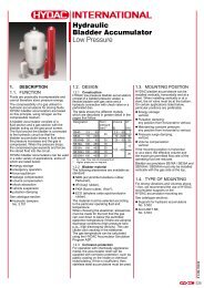
Logic ElementsBALANCED POPPET, NORMALLY CLOSED, VENT-TO-OPERATE,WITH INTEGRAL T-8A CONTROL CAVITYbT-8A CavityT-8ACav23The -8 control option allows a pilot control valve to be incorporated directlyinto the end of the cartridge via the T-8A cavity. These pilot controlcartridges are sold separately and include electro-proportional, solenoid, airpilot, and hydraulic pilot operation. See Pilot Control Cartridges on page 141.4Drainc413Pilot2Valve1 ValveNominalCapacityTypicalCartridgeModel CodeCartridge DimensionsCavity a b cDKDR-8 DKFR-8 DKHR-8 DKJR-8P = bar252015105aPerformance CurvesLocatingShoulderPiloted Open Pressure Differential vs. Flow with T-8A Pilot Stage InstalledInstallationTorque(Nm)60 L/min. DKDR – 8HN T-21A 35,0 22,2 45,2 45 - 50120 L/min. DKFR – 8HN T - 22A 35,0 28,6 50,8 60 - 70240 L/min. DKHR – 8HN T-23A 46,2 31,8 62,7 200 - 215480 L/min. DKJR – 8HN T - 24A 63,5 41,3 80,3 465 - 500P = bar252015105P = bar252015105P = bar252015105010 20 30 40 50 60Flow = L/min.020 40 60 80 100 120Flow = L/min.Pilot Pressure vs. Pilot Flow040 80 120 160 200 240Flow = L/min.080 160 240 320 400 480Flow = L/min.Flow = L/min.1.41.21.8.6.4.2Flow = L/min.1.41.21.8.6.4.2Flow = L/min.1.41.21.8.6.4.2Flow = L/min.1.41.21.8.6.4.20 50 100 150 200 250 300 350 400P = bar0 50 100 150 200 250 300 350 400P = bar0 50 100 150 200 250 300 350 400P = bar■ Maximum operating pressure = 350 bar.■ Maximum valve leakage at 24 cSt = 0,3 cc/min.■ Minimum pilot pressure required to shift valve = DKDR-8, DKFR-8: 28 bar; DKHR-8, DKJR-8: 20 bar.■ Pilot passage into valve = DKDR-8, DKFR-8: 0,8 mm; DKHR-8, DKJR-8: 1,19 mm.■ Pilot volume displacement = DKDR-8: 0,16 cc; DKFR-8: 0,33 cc; DKHR-8: 0,82 cc; DKJR-8: 2,8 cc.■ Unique balanced construction provides predictable switching with 350 bar at port 1 and port 2. Switching will onlyoccur when both minimum pilot pressure at port 3 is present and pilot control is open.■ The valves are hydraulically balanced between port 1 and port 2.■ Port 1 and port 2 are fully sealed from port 3 and port 4. Ports 3 and 4 are positively sealed.■ Leakage rate between port 1 and port 2 is less than 0,3 cc/min. at 350 bar.■ Valve will reseat when the pilot pressure falls below 10 bar.■ Any back pressure at the drain port is directly additive to the required pilot pressure for reliable operation.■ With the -8 control option, the main stage valve should first be installed to the correct torque value. The T-8Apilot control valve should then be installed into the main stage valve to its required torque value of 35-40 Nm.OPTION ORDERING INFORMATIONDK ✱ R – 8 H ✱0 50 100 150 200 250 300 350 400P = barNominalCapacityControl Minimum Pilot Pressure Seal MaterialD 60 L/min. 8 with T-8A cavity DKDR-8, DKFR-8: only: N Buna-Nin hex body forH 28 barF 120 L/min. pilot operation V VitonDKHR-8, DKJR-8:H 240 L/min. See pilot control 20 barsection for alternateJ 480 L/min. optionsVisit www.sunhydraulics.com for current list pricing and complete technical information on all <strong>Sun</strong> products.102 Int’l Shortcut <strong>Catalog</strong>ue #999-901-312
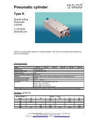
Logic ElementsBALANCED POPPET, NORMALLY CLOSED, PRESSURE ADJUSTABLEFull Adjustment 5 Turns+ -23bc414Drain3Pilot2PortPort1NominalCapacityTypicalCartridgeModel CodeCartridge DimensionscCavity a bL C KDKDP DKFP DKHP DKJPP = bar252015105aPerformance CurvesLocatingShoulderInstallationTorque(Nm)60 L/min. DKDP – LAN T-21A 35,0 22,2 79,0 82,6 84,8 45 - 50120 L/min. DKFP – LAN T - 22A 35,0 28,6 87,4 89,0 94,0 60 - 70240 L/min. DKHP – LAN T-23A 46,2 31,8 100,1 101,1 105,9 200 - 215480 L/min. DKJP – LAN T - 24A 63,5 41,3 121,5 125,0 128,0 465 - 500P = bar252015105Fully Open Pressure Differential vs. FlowP = bar252015105P = bar252015105010 20 30 40 50 60Flow = L/min.020 40 60 80 100 120Flow = L/min.Pilot Pressure vs. Pilot Flow040 80 120 160 200 240Flow = L/min.080 160 240 320 400 480Flow = L/min.Flow = L/min.1.41.21.8.6.4.2Flow = L/min.1.41.21.8.6.4.2Flow = L/min.1.41.21.8.6.4.2Flow = L/min.1.41.21.8.6.4.2■■■■■■■■■■0 50 100 150 200 250 300 350 400 0 50 100 150 200 250 300 350 4000 50 100 150 200 250 300 350 4000 50 100 150 200 250 300 350 400P = barP = barP = barP = barMaximum operating pressure = 350 bar.Maximum valve leakage at 24 cSt = 0,3 cc/min.Minimum pilot pressure required to shift valve = DKDP, DKFP: 28 bar; DKHP, DKJP: 20 bar.Pilot passage into valve = DKDP, DKFP: 0,8 mm; DKHP, DKJP: 1,19 mm.Pilot volume displacement = DKDP: 0,16 cc; DKFP: 0,33 cc; DKHP: 0,82 cc; DKJP: 2,8 cc.Unique balanced construction provides predictable switching with 350 bar at both port 1 and port 2. When the remote pressure signal atport 3 exceeds the internal valve setting, the valve shifts to the open position.Port 1 and port 2 are fully sealed from port 3 and port 4. Ports 3 and 4 are positively sealed.Leakage rate between port 1 and port 2 is less than 0,3 cc/min. at 350 bar.Any back pressure at the drain port is directly additive to the valve setting.Valve will reseat when the pilot pressure falls to 85% of the cracking value.OPTION ORDERING INFORMATIONDK ✱ P – ✱ ✱ ✱NominalCapacity Control** Adjustment Range Seal MaterialD 60 L/min. L Standard Screw DKDP, DKFP only: N Buna-NAdjustmentA 28 - 210 barF 120 L/min. Standard set at 70 bar V VitonC*Tamper ResistantB 28 - 105 barH 240 L/min. Factory Set Standard set at 70 barW 28 - 315 barJ 480 L/min. K Handknob Standard set at 70 barwith Lock KnobDKHP, DKJP:* Special setting required. A 20 - 210 barSpecify at time of order. Standard set at 70 barB 20 - 105 bar** See page 178 Standard set at 70 barfor informationW 20 - 315 baron Control OptionsStandard set at 70 barCustomer specified specialsetting stamped on hex.Visit www.sunhydraulics.com for current list pricing and complete technical information on all <strong>Sun</strong> products.Int’l Shortcut <strong>Catalog</strong>ue #999-901-312 103
- Page 1 and 2:
Over 35 New Products in this Catalo
- Page 3 and 4:
ContentsModel Codes printed in Red
- Page 5 and 6:
Relief Cartridge ValvesCartridge Ty
- Page 7 and 8:
Relief ValvesDIRECT ACTING AND DIRE
- Page 9 and 10:
Relief ValvesDIRECT ACTING, PILOT C
- Page 11 and 12:
Relief ValvesPILOT OPERATED, BALANC
- Page 13 and 14:
Relief ValvesPILOT OPERATED, BALANC
- Page 15 and 16:
Relief Valves, Electro-Proportional
- Page 17 and 18:
Relief Valves, Electro-Proportional
- Page 19 and 20:
Relief ValvesPILOT OPERATED, BALANC
- Page 21 and 22:
Relief ValvesBYPASS COMPENSATOR WIT
- Page 23 and 24:
Relief Valves, Electro-Proportional
- Page 25 and 26:
Sequence Cartridge ValvesCartridge
- Page 27 and 28:
Sequence ValvesDIRECT ACTING WITH R
- Page 29 and 30:
Sequence ValvesAIR CONTROLLED, PILO
- Page 31 and 32:
Sequence Valves, Electro-Proportion
- Page 33 and 34:
Reducing and Reducing/RelievingCart
- Page 35 and 36:
Reducing ValvesPILOT OPERATED, AIR
- Page 37 and 38:
Reducing/Relieving ValvesPILOT OPER
- Page 39 and 40:
Reducing/Relieving ValvesDIRECT ACT
- Page 41 and 42:
Reducing/Relieving ValvesPILOT OPER
- Page 43 and 44:
Reducing/Relieving Valves, Electro-
- Page 45 and 46:
Reducing/Relieving Valves, Electro-
- Page 47 and 48:
Pilot-to-Open CheckCartridge Valves
- Page 49 and 50:
Pilot-to-Open Check ValvesATMOSPHER
- Page 51 and 52: Counterbalance Cartridge ValvesCart
- Page 53 and 54: Series 2 Series 3 Series 4Pilot Rat
- Page 55 and 56: Counterbalance ValvesNON-VENTED, ST
- Page 57 and 58: Counterbalance ValvesNON-VENTED, SE
- Page 59 and 60: Counterbalance ValvesNON-VENTED, RE
- Page 61 and 62: Counterbalance ValvesVENTED, 280 BA
- Page 63 and 64: Load Control:Load Reactive Cartridg
- Page 65 and 66: Load Control: Load Reactive ValvesN
- Page 67 and 68: Load Control: Load Reactive ValvesV
- Page 69 and 70: Load Control:Balanced Cartridge Val
- Page 71 and 72: Load Control: BalancedVENTED, NON-R
- Page 73 and 74: Check Cartridge ValvesCartridge Typ
- Page 75 and 76: Check ValvesFREE FLOW, SIDE-TO-NOSE
- Page 77 and 78: Check ValvesFREE FLOW, SIDE-TO-NOSE
- Page 79 and 80: Flow Control Valves2Cartridge TypeP
- Page 81 and 82: Flow Control ValvesFULLY ADJUSTABLE
- Page 83 and 84: Flow Control ValvesFIXED ORIFICE, N
- Page 85 and 86: Flow Control ValvesFIXED ORIFICE, P
- Page 87 and 88: Flow Control ValvesFIXED ORIFICE, B
- Page 89 and 90: Flow Control ValvesVENTABLE, FIXED
- Page 91 and 92: Flow Control Valves, Electro-Propor
- Page 93 and 94: Flow Divider / CombinerCartridge Va
- Page 95 and 96: Flow Divider / Combiner ValvesDIVID
- Page 97 and 98: Flow Divider / Combiner ValvesDIVID
- Page 99 and 100: Logic ElementsCartridge Type4421213
- Page 101: Logic ElementsBALANCED POPPET, NORM
- Page 105 and 106: Logic ElementsBALANCED POPPET, NORM
- Page 107 and 108: Logic ElementsBALANCED POPPET, NORM
- Page 109 and 110: Logic ElementsUNBALANCED POPPET, VE
- Page 111 and 112: Logic ElementsUNBALANCED POPPET, PI
- Page 113 and 114: Logic ElementsNORMALLY CLOSED, MODU
- Page 115 and 116: Logic ElementsBI-DIRECTIONAL, MODUL
- Page 117 and 118: Directional Cartridge Valves123Cart
- Page 119 and 120: Directional Valves2-WAY AND 3-WAY,
- Page 121 and 122: Directional Valves2-WAY AND 3-WAY D
- Page 123 and 124: Directional Valves2-WAY AND 3-WAY,
- Page 125 and 126: Directional Valves3-WAY, 2-POSITION
- Page 127 and 128: Directional Valves2-WAY POPPET, WIT
- Page 129 and 130: Directional Valves3-POSITION, 4-WAY
- Page 131 and 132: Solenoid Operated Cartridge ValvesC
- Page 133 and 134: Solenoid Operated Cartridge Valves2
- Page 135 and 136: Solenoid Operated Cartridge Valves3
- Page 137 and 138: Solenoid Operated Cartridge Valves3
- Page 139 and 140: Solenoid Operated Cartridge Valves4
- Page 141 and 142: Pilot Control ValvesCartridge TypeP
- Page 143 and 144: Pilot Control ValvesDIRECT ACTING,
- Page 145 and 146: Pilot Control ValvesFLOW CONTROL, F
- Page 147 and 148: Pilot Control Valves2-WAY, HYDRAULI
- Page 149 and 150: Pilot Control Valves2-WAY, AIR OPER
- Page 151 and 152: Pilot Control Valves3-WAY, 2-POSITI
- Page 153 and 154:
Pilot Control Valves3-WAY, 2-POSITI
- Page 155 and 156:
Shuttle ValvesCartridge TypePage121
- Page 157 and 158:
Shuttle ValvesBACK-TO-BACK CHECK/SH
- Page 159 and 160:
Shuttle ValvesBACK-TO-BACK CHECK/SH
- Page 161 and 162:
Shuttle ValvesHIGH SIDE, 3-POSITION
- Page 163 and 164:
Circuit SaversCartridge TypePage2Fi
- Page 165 and 166:
Circuit SaversAIR BLEED AND START-U
- Page 167 and 168:
Circuit SaversCHECK, PILOT-TO-CLOSE
- Page 169 and 170:
Circuit SaversACCUMULATOR SENSE, PU
- Page 171 and 172:
Hybrid Relief ValvesCartridge TypeP
- Page 173 and 174:
Hybrid ValvesDIRECT ACTING RELIEF,
- Page 175 and 176:
Hybrid ValvesPILOT OPERATED, BALANC
- Page 177 and 178:
General InformationPageCartridge Co
- Page 179 and 180:
Cartridge Control KitsService Kit N
- Page 181 and 182:
Cartridge Control KitsService KitNu
- Page 183 and 184:
Cavity PlugsIt is sometimes desirab
- Page 185 and 186:
Cavity PlugsPlugs for Six Port Cavi
- Page 187:
Sun Coil Options for Solenoids (Met
- Page 191 and 192:
Sun Coil 790-***** Part Numbering S
- Page 193 and 194:
Sun Model Code SystemSun cartridges
- Page 195 and 196:
Model Code IndexModel Code Cavity P
- Page 197 and 198:
Model Code IndexModel Code Cavity P
- Page 199 and 200:
WarrantyWARRANTY INFORMATION,PERFOR
- Page 201:
MexicoCOUNTRYDISTRIBUTORComponentes