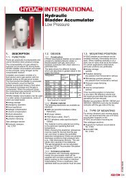
Directional Valves2-WAY AND 3-WAY DIRECT ACTING, INTERNAL DRAIN TO PORT 3Full Adjustment 5 Turns+ -22 22bc13131 3 133Port2PortPort1aLocatingShoulderDRBA DRBB DRBC DRBDCartridge DimensionsCapacityTypicalcInstallationCartridge Cavity a bTorqueModel CodeL C K (Nm)28 L/min. DRBA – LAN T - 11A 35,0 22,2 78,5 82,6 85,0 45 - 5028 L/min. DRBB – LAN T - 11A 35,0 22,2 78,5 82,6 85,0 45 - 5028 L/min. DRBC – LAN T - 11A 35,0 22,2 78,5 82,6 85,0 45 - 5028 L/min. DRBD – LAN T - 11A 35,0 22,2 78,5 82,6 85,0 45 - 50Performance CurvesDRBA DRBB DRBC DRBDTypical Pressure DropP = bar252015105Port 2to Port 3P = bar252015105Port 2to Port 3P = bar252015105Port 2to Port 3Port 1to Port 2P = bar252015105Port 1 to Port 2Port 2to Port 3010 20 30 40 500 10 20 30 40 500 10 20 30 40 500 10 20 30 40Flow = L/min. Flow = L/min. Flow = L/min. Flow = L/min.■Maximum operating pressure = 350 bar.■Maximum combined valve leakage (ports 2 and 3) = 30 cc/min. at 70 bar.■■■■■Pressure at port 3 is directly additive to the setting of the valve. Because of this, port 3 may not beuseable as a work port in your circuit. If this is a consideration, the 4 port version of this valve maybe a solution.Pilot pressure at port 3 is limited to 210 bar.Direct acting and pilot operated versions of these valves are interchangeable. They fit the same cavitiesand have the same flow paths.Because of their direct acting design, these cartridges feature low internal leakage and low pilotflow consumption.These valves are not bistable; it is capable of modulating between the two positions shown.50OPTION ORDERING INFORMATIONDR ✱✱ – ✱✱✱NominalCapacityVersion Control** Adjustment Range Seal MaterialB 28 L/min. A 2-Way, Direct Acting, L Standard Screw A 35 - 210 bar N Buna-Nwith Internal Drain to Adjustment Standard set at 70 barPort 3, Normally OpenV VitonC* Tamper Resistant B 3,5 - 105 barB 2-Way, Direct Acting, Factory Set Standard set at 14 barwith Internal Drain toPort 3, Normally Closed K Handknob with D 1,7 - 55 barLock KnobStandard set at 14 barC 3-Way, 2-Position,Direct Acting, with * Special setting required. E 1,7 - 28 barInternal Drain to Specify at time of order. Standard set at 14 barto Port 3, Port 1Blocked, 2 to 3 OpenD 3-Way, 2-Position,Direct Acting, withInternal Drain to Port 3,Port 3 Blocked, 1 to 2 Open** See page 178for informationon Control OptionsS 1,7 - 14 barStandard set at 14 barW 50 - 315 barStandard set at 70 barVisit www.sunhydraulics.com for current list pricing and complete technical information on all <strong>Sun</strong> products.Consult the <strong>Sun</strong> websitefor our most recent andcomplete informationon the full CorrosionResistant line of products.120 Int’l Shortcut <strong>Catalog</strong>ue #999-901-312
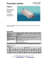
Directional Valves2-WAY AND 3-WAY DIRECT ACTING, DRAIN TO PORT 4Full Adjustment 5 Turns+ -242 42 4242 31b4Port3Port2Port1 PortPerformance CurvescaLocatingShoulder1Capacity31TypicalCartridgeModel Code31DRBM DRBN DRBO DRBP DRBR3Cartridge DimensionscCavity a bL C KInstallationTorque(Nm)28 L/min. DRBM– LAN T - 21A 35,1 22,2 78,7 80,3 84,8 45 - 5028 L/min. DRBN – LAN T - 21A 35,1 22,2 78,7 80,3 84,8 45 - 5028 L/min. DRBO – LAN T - 21A 35,1 22,2 78,7 80,3 84,8 45 - 5028 L/min. DRBP – LAN T - 21A 35,1 22,2 78,7 80,3 84,8 45 - 5028 L/min. DRBR – LAN T - 21A 35,1 22,2 78,7 80,3 84,8 45 - 50134DRBM DRBN DRBO DRBP DRBRTypical Pressure DropP = bar252015105Port 2to Port 3P = bar252015105Port 2to Port 3P = bar252015105Port 2to Port 3Port 1to Port 2P = bar252015105Port 1to Port 2Port 2to Port 3P = bar15105Flow 3 to 4Flow 2 to 3010 20 30 40Flow = L/min.50010 20 30 40Flow = L/min.50010 20 30 40Flow = L/min.■Maximum operating pressure = 350 bar.■Maximum combined valve leakage (ports 2, 3, and 4) = 30 cc/min. at 70 bar.■Maximum pressure at port 3 should be limited to 210 bar. This is due to fatigue strength limits not hydraulic operating limits.■Port 3 can be used as a work port.■Pressure at port 4 is directly additive to the setting of the valve.■Because of their direct acting design, these cartridges feature low internal leakage and low pilot flow consumption.■Direct acting and pilot operated versions of these valves are interchangeable. They fit the same cavities and have the sameflow paths.■This valve is not bistable; it is capable of modulating between the two positions shown.■DRBR: 55 bar is the highest setting possible for this valve. The flow path between ports 2 and 3 is bidirectional.OPTION ORDERING INFORMATIONDR ✱✱ – ✱✱✱10 20 30 40Flow = L/min.NominalCapacityVersion Control** Adjustment Range Seal MaterialB 28 L/min. M 2-Way, Direct Acting, L Standard Screw A 35 - 210 bar N Buna-Nwith Drain to Port 4, Adjustment Standard set at 70 barDRCO only: Normally Open B 3,5 - 105 bar V VitonC 60 L/min. N 2-Way, Direct Acting, C* Tamper Resistant Standard set at 14 barwith Drain to Port 4, Factory Set D 1,7 - 55 barNormally ClosedStandard set at 14 barO 3-Way, 2-Position, K Handknob with E 1,7 - 28 barDirect Acting, Lock Knob Standard set at 14 barwith Drain to Port 4,S 1,7 - 14 barPort 2 to 3 Open, * Special setting required. Standard set at 14 barPort 1 Blocked Specify at time of order. W 50 - 315 barP 3-Way, 2-Position,Standard set at 70 barwith Drain to Port 4,DRBR only:Port 1 to 2 Open,N 4 - 55 barPort 3 BlockedStandard set at 14 barR 3-Way, 2-Position, ** See page 178 E 1,7 - 28 barDirect Acting, for information Standard set at 14 barwith Drain to on Control Options S 1,7 - 14 barPort 4, Port 3Standard set at 14 barto Port 4 Open,Customer specifiedPort 2 Blockedspecial settingstamped on hex.Visit www.sunhydraulics.com for current list pricing and complete technical information on all <strong>Sun</strong> products.5005005 10 15 20 25 30Flow = L/min.Int’l Shortcut <strong>Catalog</strong>ue #999-901-312 121
- Page 1 and 2:
Over 35 New Products in this Catalo
- Page 3 and 4:
ContentsModel Codes printed in Red
- Page 5 and 6:
Relief Cartridge ValvesCartridge Ty
- Page 7 and 8:
Relief ValvesDIRECT ACTING AND DIRE
- Page 9 and 10:
Relief ValvesDIRECT ACTING, PILOT C
- Page 11 and 12:
Relief ValvesPILOT OPERATED, BALANC
- Page 13 and 14:
Relief ValvesPILOT OPERATED, BALANC
- Page 15 and 16:
Relief Valves, Electro-Proportional
- Page 17 and 18:
Relief Valves, Electro-Proportional
- Page 19 and 20:
Relief ValvesPILOT OPERATED, BALANC
- Page 21 and 22:
Relief ValvesBYPASS COMPENSATOR WIT
- Page 23 and 24:
Relief Valves, Electro-Proportional
- Page 25 and 26:
Sequence Cartridge ValvesCartridge
- Page 27 and 28:
Sequence ValvesDIRECT ACTING WITH R
- Page 29 and 30:
Sequence ValvesAIR CONTROLLED, PILO
- Page 31 and 32:
Sequence Valves, Electro-Proportion
- Page 33 and 34:
Reducing and Reducing/RelievingCart
- Page 35 and 36:
Reducing ValvesPILOT OPERATED, AIR
- Page 37 and 38:
Reducing/Relieving ValvesPILOT OPER
- Page 39 and 40:
Reducing/Relieving ValvesDIRECT ACT
- Page 41 and 42:
Reducing/Relieving ValvesPILOT OPER
- Page 43 and 44:
Reducing/Relieving Valves, Electro-
- Page 45 and 46:
Reducing/Relieving Valves, Electro-
- Page 47 and 48:
Pilot-to-Open CheckCartridge Valves
- Page 49 and 50:
Pilot-to-Open Check ValvesATMOSPHER
- Page 51 and 52:
Counterbalance Cartridge ValvesCart
- Page 53 and 54:
Series 2 Series 3 Series 4Pilot Rat
- Page 55 and 56:
Counterbalance ValvesNON-VENTED, ST
- Page 57 and 58:
Counterbalance ValvesNON-VENTED, SE
- Page 59 and 60:
Counterbalance ValvesNON-VENTED, RE
- Page 61 and 62:
Counterbalance ValvesVENTED, 280 BA
- Page 63 and 64:
Load Control:Load Reactive Cartridg
- Page 65 and 66:
Load Control: Load Reactive ValvesN
- Page 67 and 68:
Load Control: Load Reactive ValvesV
- Page 69 and 70: Load Control:Balanced Cartridge Val
- Page 71 and 72: Load Control: BalancedVENTED, NON-R
- Page 73 and 74: Check Cartridge ValvesCartridge Typ
- Page 75 and 76: Check ValvesFREE FLOW, SIDE-TO-NOSE
- Page 77 and 78: Check ValvesFREE FLOW, SIDE-TO-NOSE
- Page 79 and 80: Flow Control Valves2Cartridge TypeP
- Page 81 and 82: Flow Control ValvesFULLY ADJUSTABLE
- Page 83 and 84: Flow Control ValvesFIXED ORIFICE, N
- Page 85 and 86: Flow Control ValvesFIXED ORIFICE, P
- Page 87 and 88: Flow Control ValvesFIXED ORIFICE, B
- Page 89 and 90: Flow Control ValvesVENTABLE, FIXED
- Page 91 and 92: Flow Control Valves, Electro-Propor
- Page 93 and 94: Flow Divider / CombinerCartridge Va
- Page 95 and 96: Flow Divider / Combiner ValvesDIVID
- Page 97 and 98: Flow Divider / Combiner ValvesDIVID
- Page 99 and 100: Logic ElementsCartridge Type4421213
- Page 101 and 102: Logic ElementsBALANCED POPPET, NORM
- Page 103 and 104: Logic ElementsBALANCED POPPET, NORM
- Page 105 and 106: Logic ElementsBALANCED POPPET, NORM
- Page 107 and 108: Logic ElementsBALANCED POPPET, NORM
- Page 109 and 110: Logic ElementsUNBALANCED POPPET, VE
- Page 111 and 112: Logic ElementsUNBALANCED POPPET, PI
- Page 113 and 114: Logic ElementsNORMALLY CLOSED, MODU
- Page 115 and 116: Logic ElementsBI-DIRECTIONAL, MODUL
- Page 117 and 118: Directional Cartridge Valves123Cart
- Page 119: Directional Valves2-WAY AND 3-WAY,
- Page 123 and 124: Directional Valves2-WAY AND 3-WAY,
- Page 125 and 126: Directional Valves3-WAY, 2-POSITION
- Page 127 and 128: Directional Valves2-WAY POPPET, WIT
- Page 129 and 130: Directional Valves3-POSITION, 4-WAY
- Page 131 and 132: Solenoid Operated Cartridge ValvesC
- Page 133 and 134: Solenoid Operated Cartridge Valves2
- Page 135 and 136: Solenoid Operated Cartridge Valves3
- Page 137 and 138: Solenoid Operated Cartridge Valves3
- Page 139 and 140: Solenoid Operated Cartridge Valves4
- Page 141 and 142: Pilot Control ValvesCartridge TypeP
- Page 143 and 144: Pilot Control ValvesDIRECT ACTING,
- Page 145 and 146: Pilot Control ValvesFLOW CONTROL, F
- Page 147 and 148: Pilot Control Valves2-WAY, HYDRAULI
- Page 149 and 150: Pilot Control Valves2-WAY, AIR OPER
- Page 151 and 152: Pilot Control Valves3-WAY, 2-POSITI
- Page 153 and 154: Pilot Control Valves3-WAY, 2-POSITI
- Page 155 and 156: Shuttle ValvesCartridge TypePage121
- Page 157 and 158: Shuttle ValvesBACK-TO-BACK CHECK/SH
- Page 159 and 160: Shuttle ValvesBACK-TO-BACK CHECK/SH
- Page 161 and 162: Shuttle ValvesHIGH SIDE, 3-POSITION
- Page 163 and 164: Circuit SaversCartridge TypePage2Fi
- Page 165 and 166: Circuit SaversAIR BLEED AND START-U
- Page 167 and 168: Circuit SaversCHECK, PILOT-TO-CLOSE
- Page 169 and 170: Circuit SaversACCUMULATOR SENSE, PU
- Page 171 and 172:
Hybrid Relief ValvesCartridge TypeP
- Page 173 and 174:
Hybrid ValvesDIRECT ACTING RELIEF,
- Page 175 and 176:
Hybrid ValvesPILOT OPERATED, BALANC
- Page 177 and 178:
General InformationPageCartridge Co
- Page 179 and 180:
Cartridge Control KitsService Kit N
- Page 181 and 182:
Cartridge Control KitsService KitNu
- Page 183 and 184:
Cavity PlugsIt is sometimes desirab
- Page 185 and 186:
Cavity PlugsPlugs for Six Port Cavi
- Page 187:
Sun Coil Options for Solenoids (Met
- Page 191 and 192:
Sun Coil 790-***** Part Numbering S
- Page 193 and 194:
Sun Model Code SystemSun cartridges
- Page 195 and 196:
Model Code IndexModel Code Cavity P
- Page 197 and 198:
Model Code IndexModel Code Cavity P
- Page 199 and 200:
WarrantyWARRANTY INFORMATION,PERFOR
- Page 201:
MexicoCOUNTRYDISTRIBUTORComponentes