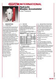
Directional Valves2-WAY AND 3-WAY, VENT-TO-OPERATE, WITH INTEGRAL T-8A CONTROL CAVITYb4PortT-8A Cavityc4T-8A3211234T-8A1234T-8A1234T-8AThe -8 control option allows the pilot controlvalve to be incorporated directly into the end ofthe cartridge via the T-8A cavity. These pilotcontrol cartridges are sold separately and includesolenoid, air pilot, and hydraulic pilot operation.See Pilot Control Cartridges on page 141.3PortLocatingShoulderDV*M-8 DV*N-8 DV*O-8 DV*P-82Port1PortPerformance CurvesaCapacityTypicalCartridgeModel CodeCartridge DimensionsCavity a b cInstallationTorque(Nm)28 L/min. DVB* – 8FN T-21A 35,1 22,2 42,9 45 - 5060 L/min. DVC* – 8FN T-22A 35,1 28,6 50,8 60 - 70DVB✱-8DVC✱-8■■■■■■■■■P = barTypical Pressure Drop withT-8A Pilot Stage Installed302418126010 20 30Flow = L/min.40Pilot Oil Flow vs. LoadPressure above Valve SettingMaximum operating pressure = 350 bar.Maximum leakage at 24 cSt = 30,0 cc/min. at 70 bar.Control pilot flow at opening = DVB*-8, DVC*-8: 0,11 - 0,16 L/min.Port 3 can be used as a work port.The flow path between port 2 and port 3 is bidirectional.Pressure at port 3 is limited to 210 bar.These valves are not bistable; it is capable of modulating between the two positions shown.There must be a pressure source at port 1, relative to port 4, to shift the valve.The main stage valve should first be installed to the correct torque value followed by the T-8A pilot control section into themain stage valve to its required torque value.OPTION ORDERING INFORMATIONFlow = L/min.1.00.80.60.40.2DV ✱✱ – 8F✱NominalCapacityVersion Control Minimum Control Pressure Seal MaterialB 28 L/min. M 2-Way, 8 T-8A Cavity in F 7 bar N Buna-NVent-to-operate,hex body forC 60 L/min. with Drain to Port 4, pilot operation V VitonNormally OpenPilot valve toN 2-Way,be orderedVent-to-operate,separatelywith Drain to Port 4,Normally ClosedO 3-Way, 2-Position,Vent-to-operate,with Drain to Port 4,Port 2 to 3 Open,Port 1 BlockedP 3-Way, 2-Position,Vent-to-operate,with Drain to Port 4,Port 1 to 2 Open,Port 3 Blocked050 100 150 200 250 300 350P = barP = barTypical Pressure Drop withT-8A Pilot Stage Installed302418126020 40 60Flow = L/min.80Pilot Oil Flow vs. LoadPressure above Valve SettingFlow = L/min.1.00.80.60.40.2050 100 150 200 250 300 350P = barVisit www.sunhydraulics.com for current list pricing and complete technical information on all <strong>Sun</strong> products.124 Int’l Shortcut <strong>Catalog</strong>ue #999-901-312
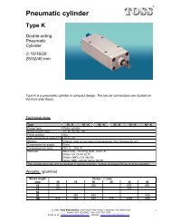
Directional Valves3-WAY, 2-POSITION VENT-TO-SHIFT, DIVERTER, NORMALLY CLOSEDb 4 2cLocatingShoulder134Port3Port2Port1PortPerformance CurvesaCapacityTypicalCartridgeModel CodeCartridge DimensionsCavity a b cInstallationTorque(Nm)60 L/min. DSCX – XEN T-31A 84,8 22,2 30,2 45 - 50120 L/min. DSEX – XEN T - 32A 92,2 28,6 33,3 60 - 70240 L/min. DSGX – XEN T-33A 114,6 31,8 41,4 200 - 215480 L/min. DSIX – XEN T - 34A 139,7 41,3 53,8 465 - 500DSCXDSEXDSGXDSIXTypical Pressure DropP = bar2015105 XDNXENXCN0 20 40 60■■■■■■■■Flow3 to 2Flow = L/min.Flow3 to 480P = bar201510XEN5XDNXCNFlow3 to 2Flow3 to 40 25 50 75 100 125Flow = L/min.P = bar2015105XDNXENXCN0 50 100 150 200 250Flow = L/min.Maximum operating pressure = 350 bar.Pressure compensated vent flow = DSCX, DSEX: 0,38 L/min.; DSGX, DSIX: 0,60 L/min.There must be a pressure source at port 3, relative to port 1, to shift the valve.The pressure at port 3 must be greater than port 1 and is dependant on the minimum control pressureselected.One application of this valve is to bypass divider/combiner valves in a limited-slip tractive circuit.Closed, the oil must go through the divider/combiner valves. Open, there is a large path around thedivider/combiner valves for efficient high speed operation.One pilot valve may be used; to vent multiple diverter valves if blocking checks are used at port 1of eachdiverter. If blocking checks are not used, there will be interaction between high and low pressure legs ofthe circuits.Hardened spool and sleeve provide consistent and low spool leakage rates and excellent wearcharacteristics.The valve is not bistable; it is capable of modulation between the two positions shown.Flow3 to 4Flow3 to 2P = bar201510XEN5XDNXCNFlow3 to 20 100 200 300 400Flow = L/min.Flow3 to 4500OPTION ORDERING INFORMATIONDS ✱ X – X E ✱NominalCapacityControl Minimum Control Pressure Seal MaterialC 60 L/min. X Not Adjustable C 2 bar N Buna-NE 120 L/min. D 3,5 bar V VitonG 240 L/min. E 5 barI480 L/min.Visit www.sunhydraulics.com for current list pricing and complete technical information on all <strong>Sun</strong> products.Int’l Shortcut <strong>Catalog</strong>ue #999-901-312 125
- Page 1 and 2:
Over 35 New Products in this Catalo
- Page 3 and 4:
ContentsModel Codes printed in Red
- Page 5 and 6:
Relief Cartridge ValvesCartridge Ty
- Page 7 and 8:
Relief ValvesDIRECT ACTING AND DIRE
- Page 9 and 10:
Relief ValvesDIRECT ACTING, PILOT C
- Page 11 and 12:
Relief ValvesPILOT OPERATED, BALANC
- Page 13 and 14:
Relief ValvesPILOT OPERATED, BALANC
- Page 15 and 16:
Relief Valves, Electro-Proportional
- Page 17 and 18:
Relief Valves, Electro-Proportional
- Page 19 and 20:
Relief ValvesPILOT OPERATED, BALANC
- Page 21 and 22:
Relief ValvesBYPASS COMPENSATOR WIT
- Page 23 and 24:
Relief Valves, Electro-Proportional
- Page 25 and 26:
Sequence Cartridge ValvesCartridge
- Page 27 and 28:
Sequence ValvesDIRECT ACTING WITH R
- Page 29 and 30:
Sequence ValvesAIR CONTROLLED, PILO
- Page 31 and 32:
Sequence Valves, Electro-Proportion
- Page 33 and 34:
Reducing and Reducing/RelievingCart
- Page 35 and 36:
Reducing ValvesPILOT OPERATED, AIR
- Page 37 and 38:
Reducing/Relieving ValvesPILOT OPER
- Page 39 and 40:
Reducing/Relieving ValvesDIRECT ACT
- Page 41 and 42:
Reducing/Relieving ValvesPILOT OPER
- Page 43 and 44:
Reducing/Relieving Valves, Electro-
- Page 45 and 46:
Reducing/Relieving Valves, Electro-
- Page 47 and 48:
Pilot-to-Open CheckCartridge Valves
- Page 49 and 50:
Pilot-to-Open Check ValvesATMOSPHER
- Page 51 and 52:
Counterbalance Cartridge ValvesCart
- Page 53 and 54:
Series 2 Series 3 Series 4Pilot Rat
- Page 55 and 56:
Counterbalance ValvesNON-VENTED, ST
- Page 57 and 58:
Counterbalance ValvesNON-VENTED, SE
- Page 59 and 60:
Counterbalance ValvesNON-VENTED, RE
- Page 61 and 62:
Counterbalance ValvesVENTED, 280 BA
- Page 63 and 64:
Load Control:Load Reactive Cartridg
- Page 65 and 66:
Load Control: Load Reactive ValvesN
- Page 67 and 68:
Load Control: Load Reactive ValvesV
- Page 69 and 70:
Load Control:Balanced Cartridge Val
- Page 71 and 72:
Load Control: BalancedVENTED, NON-R
- Page 73 and 74: Check Cartridge ValvesCartridge Typ
- Page 75 and 76: Check ValvesFREE FLOW, SIDE-TO-NOSE
- Page 77 and 78: Check ValvesFREE FLOW, SIDE-TO-NOSE
- Page 79 and 80: Flow Control Valves2Cartridge TypeP
- Page 81 and 82: Flow Control ValvesFULLY ADJUSTABLE
- Page 83 and 84: Flow Control ValvesFIXED ORIFICE, N
- Page 85 and 86: Flow Control ValvesFIXED ORIFICE, P
- Page 87 and 88: Flow Control ValvesFIXED ORIFICE, B
- Page 89 and 90: Flow Control ValvesVENTABLE, FIXED
- Page 91 and 92: Flow Control Valves, Electro-Propor
- Page 93 and 94: Flow Divider / CombinerCartridge Va
- Page 95 and 96: Flow Divider / Combiner ValvesDIVID
- Page 97 and 98: Flow Divider / Combiner ValvesDIVID
- Page 99 and 100: Logic ElementsCartridge Type4421213
- Page 101 and 102: Logic ElementsBALANCED POPPET, NORM
- Page 103 and 104: Logic ElementsBALANCED POPPET, NORM
- Page 105 and 106: Logic ElementsBALANCED POPPET, NORM
- Page 107 and 108: Logic ElementsBALANCED POPPET, NORM
- Page 109 and 110: Logic ElementsUNBALANCED POPPET, VE
- Page 111 and 112: Logic ElementsUNBALANCED POPPET, PI
- Page 113 and 114: Logic ElementsNORMALLY CLOSED, MODU
- Page 115 and 116: Logic ElementsBI-DIRECTIONAL, MODUL
- Page 117 and 118: Directional Cartridge Valves123Cart
- Page 119 and 120: Directional Valves2-WAY AND 3-WAY,
- Page 121 and 122: Directional Valves2-WAY AND 3-WAY D
- Page 123: Directional Valves2-WAY AND 3-WAY,
- Page 127 and 128: Directional Valves2-WAY POPPET, WIT
- Page 129 and 130: Directional Valves3-POSITION, 4-WAY
- Page 131 and 132: Solenoid Operated Cartridge ValvesC
- Page 133 and 134: Solenoid Operated Cartridge Valves2
- Page 135 and 136: Solenoid Operated Cartridge Valves3
- Page 137 and 138: Solenoid Operated Cartridge Valves3
- Page 139 and 140: Solenoid Operated Cartridge Valves4
- Page 141 and 142: Pilot Control ValvesCartridge TypeP
- Page 143 and 144: Pilot Control ValvesDIRECT ACTING,
- Page 145 and 146: Pilot Control ValvesFLOW CONTROL, F
- Page 147 and 148: Pilot Control Valves2-WAY, HYDRAULI
- Page 149 and 150: Pilot Control Valves2-WAY, AIR OPER
- Page 151 and 152: Pilot Control Valves3-WAY, 2-POSITI
- Page 153 and 154: Pilot Control Valves3-WAY, 2-POSITI
- Page 155 and 156: Shuttle ValvesCartridge TypePage121
- Page 157 and 158: Shuttle ValvesBACK-TO-BACK CHECK/SH
- Page 159 and 160: Shuttle ValvesBACK-TO-BACK CHECK/SH
- Page 161 and 162: Shuttle ValvesHIGH SIDE, 3-POSITION
- Page 163 and 164: Circuit SaversCartridge TypePage2Fi
- Page 165 and 166: Circuit SaversAIR BLEED AND START-U
- Page 167 and 168: Circuit SaversCHECK, PILOT-TO-CLOSE
- Page 169 and 170: Circuit SaversACCUMULATOR SENSE, PU
- Page 171 and 172: Hybrid Relief ValvesCartridge TypeP
- Page 173 and 174: Hybrid ValvesDIRECT ACTING RELIEF,
- Page 175 and 176:
Hybrid ValvesPILOT OPERATED, BALANC
- Page 177 and 178:
General InformationPageCartridge Co
- Page 179 and 180:
Cartridge Control KitsService Kit N
- Page 181 and 182:
Cartridge Control KitsService KitNu
- Page 183 and 184:
Cavity PlugsIt is sometimes desirab
- Page 185 and 186:
Cavity PlugsPlugs for Six Port Cavi
- Page 187:
Sun Coil Options for Solenoids (Met
- Page 191 and 192:
Sun Coil 790-***** Part Numbering S
- Page 193 and 194:
Sun Model Code SystemSun cartridges
- Page 195 and 196:
Model Code IndexModel Code Cavity P
- Page 197 and 198:
Model Code IndexModel Code Cavity P
- Page 199 and 200:
WarrantyWARRANTY INFORMATION,PERFOR
- Page 201:
MexicoCOUNTRYDISTRIBUTORComponentes