- Page 3 and 4:
Table of ContentsProduct Overview .
- Page 5 and 6:
Setting Up SNMP Managers . . . . .
- Page 7 and 8:
List of FiguresFigure 1-1 AsantéVi
- Page 9 and 10:
Figure 6-15 Zone Filter List window
- Page 11 and 12:
List of TablesTable 1-1 Hardware Sp
- Page 13 and 14:
Product OverviewAsantéView 2.6Feat
- Page 15 and 16:
WhatTypographicChanges andSymbols M
- Page 17 and 18:
Installing AsantéView SoftwareHard
- Page 19 and 20:
Installing AsantéView SoftwareInst
- Page 21 and 22:
Installing AsantéView SoftwareLogg
- Page 23 and 24:
Installing AsantéView SoftwareLogg
- Page 25 and 26:
Mapping the NetworkMappingNetworkSe
- Page 27 and 28:
Mapping the NetworkUsing the Map Ed
- Page 29 and 30:
Mapping the NetworkThe Map Editor T
- Page 31 and 32:
Mapping the NetworkTo remove a text
- Page 33 and 34:
Mapping the NetworkTo modify the co
- Page 35 and 36:
Mapping the NetworkAdd Device ToolU
- Page 37 and 38:
Mapping the NetworkModify Device To
- Page 39 and 40: Mapping the NetworkBuilding a MapAs
- Page 41 and 42: Mapping the NetworkChanging MapsUse
- Page 43 and 44: Mapping the NetworkBuilding aHierar
- Page 45 and 46: Mapping the NetworkCreating a Paren
- Page 47 and 48: Mapping the NetworkCreating a Child
- Page 49 and 50: Mapping the NetworkUsing Window Ico
- Page 51 and 52: Using the Panel ViewAbout PanelView
- Page 53 and 54: Using the Panel ViewIf a link is at
- Page 55 and 56: Using the Panel ViewAsantéHub 2072
- Page 57 and 58: Using the Panel ViewModule Port Sel
- Page 59 and 60: Using the Panel ViewThe following p
- Page 61 and 62: Using the Panel ViewConfiguration/I
- Page 63 and 64: Using the Panel ViewFault/Reset Rep
- Page 65 and 66: Using the Panel ViewTo display brid
- Page 67 and 68: Using the Panel ViewThe AsantéBrid
- Page 69 and 70: Using the Panel ViewThe AsantéNetR
- Page 71 and 72: Using the Panel ViewConfiguration/S
- Page 73 and 74: Using the Panel ViewPerformance/Sta
- Page 75 and 76: Using the Panel ViewAsantéFAST 100
- Page 77 and 78: Using the Panel ViewThis feature is
- Page 79 and 80: Configuring Asanté HubsSetting SNM
- Page 81 and 82: Configuring Asanté HubsFrom the Ag
- Page 83 and 84: Configuring Asanté HubsField NameB
- Page 85 and 86: Configuring Asanté HubsConfiguring
- Page 87 and 88: Configuring Asanté HubsBank Select
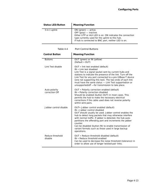
- Page 89: Configuring Asanté HubsStatus LEDs
- Page 93 and 94: Configuring Asanté BridgesBridge S
- Page 95 and 96: Configuring Asanté BridgesSpanning
- Page 97 and 98: Configuring Asanté BridgesSpanning
- Page 99 and 100: Configuring Asanté BridgesBridge S
- Page 101 and 102: Configuring Asanté Bridges❏❏
- Page 103 and 104: Configuring Asanté BridgesExpandin
- Page 105 and 106: Configuring Asanté BridgesConfigur
- Page 107 and 108: Configuring Asanté BridgesBridge D
- Page 109 and 110: Configuring Asanté BridgesThe foll
- Page 111 and 112: Configuring Asanté BridgesBridge R
- Page 113 and 114: Configuring Asanté BridgesRefreshR
- Page 115 and 116: 6Configuring the NetRASRemote Acces
- Page 117 and 118: Initializing the NetRAS67891011Ente
- Page 119 and 120: Initializing the NetRAS4567Enter an
- Page 121 and 122: Defining NetRAS Information∆You c
- Page 123 and 124: Defining NetRAS InformationFigure 6
- Page 125 and 126: Defining NetRAS InformationThis tim
- Page 127 and 128: Defining NetRAS InformationChoose D
- Page 129 and 130: Configuring PortsModifying a PortCo
- Page 131 and 132: Configuring PortsDial Scriptuds 322
- Page 133 and 134: Editing the Server Modem Configurat
- Page 135 and 136: Editing the Server Modem Configurat
- Page 137 and 138: Setting Up SNMP Managers❏To modif
- Page 139 and 140: Configuring the Zone Filter ListAdd
- Page 141 and 142:
Configuring the Zone Filter ListYou
- Page 143 and 144:
Configuring the Zone Filter List❏
- Page 145 and 146:
7General NetworkConfiguration• Co
- Page 147 and 148:
Controlling Access❏❏❏Control,
- Page 149 and 150:
Controlling AccessChanging a Passwo
- Page 151 and 152:
Resetting a HubResetting a HubUse t
- Page 153 and 154:
Setting Trap ReceiversSetting TrapR
- Page 155 and 156:
Software UpgradesSoftwareUpgradesUp
- Page 157 and 158:
Software Upgrades56In the S/W versi
- Page 159 and 160:
Software UpgradesThe message shown
- Page 161 and 162:
Software UpgradesThis record shows
- Page 163 and 164:
AsantéView 2.6 Can Page YouTable 7
- Page 165 and 166:
Setting ThresholdsSettingThresholds
- Page 167 and 168:
Setting ThresholdsField NameActionI
- Page 169 and 170:
Programming Node Intrusion AlarmsPr
- Page 171 and 172:
Finding TalkersFinding TalkersFind
- Page 173 and 174:
Edit Node DatabaseEdit NodeDatabase
- Page 175 and 176:
Monitoring the NetworkIntroductionA
- Page 177 and 178:
Monitoring the NetworkFigure 8-3Sam
- Page 179 and 180:
Monitoring the NetworkUsing the Hub
- Page 181 and 182:
Monitoring the NetworkNetworkStatis
- Page 183 and 184:
Monitoring the Network❏❏❏❏
- Page 185 and 186:
Monitoring the NetworkPacketDistrib
- Page 187 and 188:
Monitoring the NetworkNetwork Analy
- Page 189 and 190:
Monitoring the NetworkUtilization T
- Page 191 and 192:
Monitoring the NetworkOther Monitor
- Page 193 and 194:
Monitoring the NetworkTable 8-5Node
- Page 195 and 196:
Monitoring the NetworkIP MappingUse
- Page 197 and 198:
Monitoring the NetworkPingUse the P
- Page 199 and 200:
Monitoring the NetworkTo view histo
- Page 201 and 202:
Monitoring the NetworkTable 8-8Cate
- Page 203 and 204:
Monitoring the NetworkFigure 8-19 D
- Page 205 and 206:
Monitoring the NetworkFigure 8-20Le
- Page 207 and 208:
Monitoring the NetworkTable 8-11Con
- Page 209 and 210:
Monitoring the NetworkThe Misc.txt
- Page 211 and 212:
Monitoring the NetworkField Content
- Page 213 and 214:
Monitoring the NetworkTraffic Stati
- Page 215 and 216:
Monitoring the NetworkRetrieving Da
- Page 217 and 218:
Monitoring the NetworkUsing MIB IIU
- Page 219 and 220:
Appendix ATechnical SupportAsanté
- Page 221 and 222:
Bbackbone, network, map icon 2-3bau
- Page 223 and 224:
hub (continued)community strings, v
- Page 225 and 226:
monitoring the network 8-2alert mes
- Page 227 and 228:
port (continued)designated, viewing
- Page 229:
user (continued)levels (continued)l