Intel 631xESB/632xESB I/O Controller Hub - Viglen Download
Intel 631xESB/632xESB I/O Controller Hub - Viglen Download
Intel 631xESB/632xESB I/O Controller Hub - Viglen Download

You also want an ePaper? Increase the reach of your titles
YUMPU automatically turns print PDFs into web optimized ePapers that Google loves.
<strong>Intel</strong> ® <strong>631xESB</strong>/<strong>632xESB</strong> I/O<strong>Controller</strong> <strong>Hub</strong>DatasheetMay 2006Document Number: 313082-001
<strong>Intel</strong> ® <strong>631xESB</strong>/<strong>632xESB</strong> I/O <strong>Controller</strong> <strong>Hub</strong>Features• Interfaces to Memory <strong>Controller</strong> <strong>Hub</strong>— Enterprise South Bridge Interface: 1 GB/seach direction, full duplex, transparent tosoftware— x4/x8 PCI Express* interface• PCI Express Root Port— 4 PCI Express root ports— Fully PCI Express 1.0a compliant— Can be statically configured as 4x1, or 1x4— Support for full 2.5 Gb/s bandwidth in eachdirection— Module-based Hot-Plug supported• PCI Express Downstream Ports— Two x4 or one x8 PCI Express 1.0a compliantports— Hot-Plug support for Evolutionary (card-edge)form factor• PCI Bus Interface— Supports PCI Rev 2.3 Specification at 33 MHz— Seven available PCI REQ/GNT pairs— Support for 64-bit addressing on PCI usingDAC protocol• PCI/PCI-X* Bus Interface— Configurable as 33- or 66- MHz PCI, 66-,100-, or 133-MHz PCI-X— Supports Standard Hot-Plug <strong>Controller</strong> 1.0Specification• Integrated Serial ATA Host <strong>Controller</strong>— Independent DMA operation on six ports— Data transfer rates up to 3.0 Gb/s (300 MB/s)— Tri-state modes to enable swap bay• Integrated IDE <strong>Controller</strong>— Independent timing of up to two drives— Ultra ATA/100/66/33, BMIDE and PIO modes• USB 2.0— Includes four UHCI Host <strong>Controller</strong>s,increasing the number of external ports toeight— Includes one EHCI Host <strong>Controller</strong> thatsupports all eight ports— Includes one USB 2.0 High-speed Debug Port— Supports wake-up from sleeping states S1-S5— Supports legacy Keyboard/Mouse software• High Definition Audio Interface— Independent Bus Master logic for eightgeneral purpose streams: four input and fouroutput— Support three external Codecs— Supports variable length stream slots— Supports 8 channel, 24-bit samples, 192 kHzsample rate output— Supports an array of up to six microphoneinputs— Supports memory-based command/responsetransport— Provides cadence for non-48 kHz samplingoutput• AC-Link for Audio and Telephony CODECs— Support for three AC ‘97 2.3 codecs.— Independent Bus Master logic for 8 channels(PCM In/Out, PCM 2 In, Mic 1 Input, Mic 2Input, Modem In/Out, S/PDIF Out)— Support for up to six channels of PCM audiooutput (full AC3 decode)• Timers Based on 82C54— System timer, Refresh request, speaker toneoutput• Power Management Logic— ACPI 2.0 compliant— ACPI-defined power states— ACPI Power Management Timer— PME# support— SMI# generation— All registers readable/restorable for properresume from 0 V suspend states• External Glue Integration— Integrated pull-up, pull-down and seriestermination resistors on IDE, processorinterface— Integrated pull-down and series resistors onUSB• Enhanced DMA <strong>Controller</strong>— Two cascaded 8237 DMA controllers— Supports LPC DMA• Integrated dual-gigabit Media Access <strong>Controller</strong>— Compliant with the 1000 Mb/secEthernet/802.3z specification— Multi-speed operation: 10/100/1000Mb/s— Serial FLASH interface and SPI EEPROMinterface. No support for uWire EEPROM.— SERDES interface for System interconnect• Kumeran interface to external Gigabit Ethernet PHY— Dual Kumeran interface to two external1000BASE-T PHYs— 4 pin per port interface (dual port)— In band MDIO for faster accesses— Remote PHY debug and diagnostics• Integrated Board Management <strong>Controller</strong>— Full BMC implementation, meaning astandalone microcontroller with independentI/Os and memory— Expansion bus for use with external FLASHdevice, SRAM and SDRAM— 256 Kbytes of internal SRAM— Support for RMCP+— Cryptographic module, supporting AES andRC4 encryption algorithms and SHA1 andMD5 authentication algorithms• External Board Management <strong>Controller</strong> Support— Pass Through and Super Pass Throughcapable via a TCO port— TCO port supports SMBus, Fast ManagementLink (FML), and I 2 C commands for passingtraffic— Manageability Fail-Over— IDE re-direction— Serial over LAN (SoL)— RMCP+ support<strong>Intel</strong> ® <strong>631xESB</strong>/<strong>632xESB</strong> I/O <strong>Controller</strong> <strong>Hub</strong> Datasheet 3
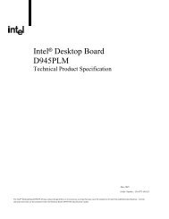
<strong>Intel</strong> ® <strong>631xESB</strong>/<strong>632xESB</strong> I/O <strong>Controller</strong> <strong>Hub</strong> DiagramLSIOLSIOAudio8x USBFlashLPCESINorthBridgeBridgeBMC<strong>Intel</strong> ® <strong>631xESB</strong> /<strong>632xESB</strong>I/O <strong>Controller</strong> <strong>Hub</strong>2<strong>Intel</strong>® 5000SeriesChipsets2X4 or 1X8 PCI ExpressDual GbEMAC82563 EB/82564 Gilgal EB6PortSATAIDEPCI -32/33PCI Express4 x1PCI-X Two PCI Express x4,1x4 Or 1 PCI Express x84 <strong>Intel</strong> ® <strong>631xESB</strong>/<strong>632xESB</strong> I/O <strong>Controller</strong> <strong>Hub</strong> Datasheet
Contents1 Introduction............................................................................................................ 371.1 About This Document......................................................................................... 371.2 Overview ......................................................................................................... 401.3 <strong>Intel</strong> ® <strong>631xESB</strong>/<strong>632xESB</strong> I/O <strong>Controller</strong> <strong>Hub</strong> SKU Definition ................................... 482 Signal Descriptions.................................................................................................. 492.1 Enterprise South Bridge Interface (ESI) to Host <strong>Controller</strong> ...................................... 532.2 PCI Express* Interface....................................................................................... 532.3 PCI Interface .................................................................................................... 542.4 PCI/PCI-X* Bus Interface ................................................................................... 572.5 PCI/PCI-X* Bus Interface 64-bit Extension............................................................ 592.6 PCI/PCI-X Hot-Plug Interface .............................................................................. 592.7 Interrupt Interface ............................................................................................ 632.8 Kumeran and SERDES Interface .......................................................................... 642.9 Serial ATA Interface........................................................................................... 642.10 IDE Interface .................................................................................................... 652.11 Firmware <strong>Hub</strong> Interface...................................................................................... 662.13 USB Interface ................................................................................................... 672.14 AC ‘97 Link....................................................................................................... 682.15 Processor Interface............................................................................................ 682.16 SMBus Interface................................................................................................ 702.17 Power Management Interface.............................................................................. 702.18 System Management Interface............................................................................ 712.19 Flash and EEPROM Interface ............................................................................... 722.20 Expansion Bus Interface..................................................................................... 722.21 RS-232 Interface............................................................................................... 732.22 Real Time Clock Interface ................................................................................... 732.23 JTAG Interface .................................................................................................. 742.24 Other Clocks..................................................................................................... 742.25 General Purpose I/O .......................................................................................... 742.26 Miscellaneous Signals ........................................................................................ 762.27 Power and Ground............................................................................................. 772.28 Pin Straps ........................................................................................................ 792.29 <strong>Intel</strong> ® <strong>631xESB</strong>/<strong>632xESB</strong> I/O <strong>Controller</strong> <strong>Hub</strong> Revision and Device ID Table ............... 823 <strong>Intel</strong> ® <strong>631xESB</strong>/<strong>632xESB</strong> I/O <strong>Controller</strong> <strong>Hub</strong> and System Clock Domains ............... 854 <strong>Intel</strong> ® <strong>631xESB</strong>/<strong>632xESB</strong> I/O <strong>Controller</strong> <strong>Hub</strong> Pin States ......................................... 874.1 Integrated Pull-Ups and Pull-Downs ..................................................................... 874.2 IDE Integrated Series Termination Resistors ......................................................... 914.3 Output and I/O Signals Planes and States............................................................. 914.4 Power Planes for Input Signals ............................................................................ 975 Functional Description........................................................................................... 1015.1 PCI Express* Bridge, Switch, and Endpoints........................................................ 1035.1.1 PCI Express* Upstream Ports .............................................................. 1035.1.2 PCI Express* to PCI-X* Bridge (Bm:D0:F3)........................................... 1045.1.3 PCI Express* Downstream Ports (Bp:D0:F0; Bp:D1:F0).......................... 1165.1.4 I/OxAPIC Devices (Bm:D0:F1). ........................................................... 1215.1.5 Flow Control ..................................................................................... 1245.2 PCI Express* Root Ports (D28:F0,F1,F2,F3) ........................................................ 1255.2.1 Interrupt Generation .......................................................................... 1255.2.2 Power Management ........................................................................... 1265.2.3 SERR# Generation............................................................................. 127<strong>Intel</strong> ® <strong>631xESB</strong>/<strong>632xESB</strong> I/O <strong>Controller</strong> <strong>Hub</strong> Datasheet 5
5.20.3 Data Encoding and Bit Stuffing ............................................................ 2395.20.4 Bus Protocol ......................................................................................2395.20.5 Packet Formats..................................................................................2405.20.6 USB Interrupts ..................................................................................2405.20.7 USB Power Management ..................................................................... 2425.20.8 USB Legacy Keyboard Operation .......................................................... 2435.21 USB EHCI Host <strong>Controller</strong> (D29:F7).................................................................... 2465.21.1 EHC Initialization ............................................................................... 2465.21.2 Data Structures in Main Memory .......................................................... 2475.21.3 USB 2.0 Enhanced Host <strong>Controller</strong> DMA ................................................2475.21.4 Data Encoding and Bit Stuffing ............................................................ 2475.21.5 Packet Formats..................................................................................2475.21.6 USB 2.0 Interrupts and Error Conditions ............................................... 2475.21.7 USB 2.0 Power Management................................................................ 2485.21.8 Interaction with UHCI Host <strong>Controller</strong>s.................................................. 2505.21.9 USB 2.0 Legacy Keyboard Operation..................................................... 2525.21.10 USB 2.0 Based Debug Port .................................................................. 2525.22 SMBus............................................................................................................ 2575.22.1 SMBus <strong>Controller</strong> (D31:F3).................................................................. 2575.22.2 SMBus Slave Interface in PCI Express to PCI-X Bridge.............................2695.23 AC’97 <strong>Controller</strong> (Audio D31:F5, Modem D31:F6)................................................. 2765.23.1 PCI Power Management ...................................................................... 2785.23.2 AC-Link Overview .............................................................................. 2795.23.3 AC-Link Low Power Mode .................................................................... 2825.23.4 AC’97 Cold Reset ............................................................................... 2835.23.5 AC’97 Warm Reset ............................................................................. 2835.23.6 Hardware Assist to Determine ACZ_SDIN Used Per Codec ....................... 2845.24 <strong>Intel</strong>® High Definition Audio <strong>Controller</strong> Overview ................................................. 2846 Electrical Characteristics........................................................................................ 2877 Component Ballout................................................................................................. 3037.1 <strong>Intel</strong> ® <strong>631xESB</strong>/<strong>632xESB</strong> I/O <strong>Controller</strong> <strong>Hub</strong> Ballout ............................................3038 Signal Lists ............................................................................................................ 3078.1 <strong>Intel</strong> ® <strong>631xESB</strong>/<strong>632xESB</strong> I/O <strong>Controller</strong> <strong>Hub</strong> Signal List (Sorted by Signal Name) .... 3078.2 <strong>Intel</strong> ® <strong>631xESB</strong>/<strong>632xESB</strong> I/O <strong>Controller</strong> <strong>Hub</strong> Signal List (Sorted by Ball Number)..... 3239 Mechanical Specifications ......................................................................................33910 Testability.............................................................................................................. 34310.1 JTAG Test Mode Description .............................................................................. 34310.2 XOR Chain Test Mode Description ...................................................................... 34410.2.1 XOR Chain Testability Algorithm Example .............................................. 34510.3 XOR Chain Tables ............................................................................................ 34511 Register and Memory Mapping ............................................................................... 35111.1 Register Nomenclature and Access Attributes ...................................................... 35111.2 PCI Devices and Functions ................................................................................ 35211.3 PCI Configuration Map ......................................................................................35311.4 I/O Map.......................................................................................................... 35311.4.1 Fixed I/O Address Ranges ...................................................................35311.4.2 Variable I/O Decode Ranges ................................................................ 35511.5 Memory Map ................................................................................................... 35612 Chipset Configuration Registers ............................................................................. 35912.1 Chipset Configuration Registers (Memory Space) ................................................. 35912.1.1 VCH – Virtual Channel Capability Header Register................................... 36112.1.2 VCAP1 – Virtual Channel Capability #1 Register ..................................... 36112.1.3 VCAP2 – Virtual Channel Capability #2 Register ..................................... 3618 <strong>Intel</strong> ® <strong>631xESB</strong>/<strong>632xESB</strong> I/O <strong>Controller</strong> <strong>Hub</strong> Datasheet
12.1.4 PVC – Port Virtual Channel Control Register .......................................... 36212.1.5 PVS – Port Virtual Channel Status Register............................................ 36212.1.6 V0CAP – Virtual Channel 0 Resource Capability Register ......................... 36212.1.7 V0CTL – Virtual Channel 0 Resource Control Register ............................. 36212.1.8 V0STS – Virtual Channel 0 Resource Status Register .............................. 36312.1.9 V1CAP – Virtual Channel 1 Resource Capability Register ......................... 36312.1.10 V1CTL – Virtual Channel 1 Resource Control Register ............................. 36412.1.11 V1STS – Virtual Channel 1 Resource Status Register .............................. 36412.1.12 PAT[0-F] – Port Arbitration Table Register............................................. 36412.1.13 UES – Uncorrectable Error Status Register ............................................ 36512.1.14 UEM – Uncorrectable Error Mask Register.............................................. 36512.1.15 UEV – Uncorrectable Error Severity Register.......................................... 36612.1.16 CES – Correctable Error Status Register ............................................... 36612.1.17 CEM – Correctable Error Mask Register ................................................. 36612.1.18 AECC – Advanced Error Capabilities and Control Register ........................ 36712.1.19 RES – Root Error Status Register ......................................................... 36712.1.20 ESID – Error Source Identification Register ........................................... 36712.1.21 RCTCL – Root Complex Topology Capabilities List Register ...................... 36812.1.22 ESD – Element Self Description Register ............................................... 36812.1.23 ULD – Upstream Link Descriptor Register.............................................. 36812.1.24 ULBA – Upstream Link Base Address Register........................................ 36812.1.25 RP0D – Root Port 0 Descriptor Register ................................................ 36912.1.26 RP0BA – Root Port 0 Base Address Register .......................................... 36912.1.27 RP1D – Root Port 1 Descriptor Register ................................................ 36912.1.28 RP1BA – Root Port 1 Base Address Register .......................................... 37012.1.29 RP2D – Root Port 2 Descriptor Register ................................................ 37012.1.30 RP2BA – Root Port 2 Base Address Register .......................................... 37012.1.31 RP3D – Root Port 3 Descriptor Register ................................................ 37112.1.32 RP3BA – Root Port 3 Base Address Register .......................................... 37112.1.33 AZD – High Definition Audio Descriptor Register .................................... 37112.1.34 AZBA – High Definition Audio Base Address Register .............................. 37212.1.35 ILCL – Internal Link Capabilities List Register ........................................ 37212.1.36 LCAP – Link Capabilities Register ......................................................... 37212.1.37 LCTL – Link Control Register ............................................................... 37312.1.38 LSTS – Link Status Register ................................................................ 37312.1.39 VPCAP – Private Virtual Channel Resource Capability Register.................. 37312.1.40 VPCTL – Private Virtual Channel Resource Control Register...................... 37412.1.41 VPSTS – Private Virtual Channel Resource Status Register ...................... 37412.1.42 VPR – Private Virtual Channel Routing Register ...................................... 37412.1.43 L3A – Level 3 Backbone Arbiter Configuration Register ........................... 37512.1.44 L2A – Level 2 Backbone Arbiter Configuration Register ........................... 37512.1.45 L1A – Level 1 Backbone Arbiter Configuration Register ........................... 37612.1.46 DA – Downstream Arbiter Configuration Register ................................... 37612.1.47 UNRL – Upstream Non-posted Request Limits Register ........................... 37712.1.48 UMR – Upstream Minimum Reserved Register........................................ 37812.1.49 QL – Queue Limits Register................................................................. 37812.1.50 GBC – Generic Backbone Configuration Register .................................... 37912.1.51 RPC – Root Port Configuration Register................................................. 38012.1.52 BAC – Bandwidth Allocation Configuration Register................................. 38012.1.53 AS – Arbiter Status Register................................................................ 38112.1.54 TRSR – Trap Status Register ............................................................... 38112.1.55 TRCR – Trapped Cycle Register............................................................ 38212.1.56 TWDR – Trapped Write Data Register ................................................... 38212.1.57 IOTRn – I/O Trap Register (0-3) .......................................................... 38212.1.58 TCTL – TCO Configuration Register ...................................................... 38312.1.59 D31IP – Device 31 Interrupt Pin Register .............................................. 384<strong>Intel</strong> ® <strong>631xESB</strong>/<strong>632xESB</strong> I/O <strong>Controller</strong> <strong>Hub</strong> Datasheet 9
12.1.60 D30IP – Device 30 Interrupt Pin Register .............................................. 38412.1.61 D29IP – Device 29 Interrupt Pin Register .............................................. 38512.1.62 D28IP – Device 28 Interrupt Pin Register .............................................. 38612.1.63 D27IP – Device 27 Interrupt Pin Register .............................................. 38612.1.64 D31IR – Device 31 Interrupt Route Register .......................................... 38712.1.65 D30IR – Device 30 Interrupt Route Register .......................................... 38812.1.66 D29IR – Device 29 Interrupt Route Register .......................................... 38912.1.67 D28IR – Device 28 Interrupt Route Register .......................................... 39012.1.68 D27IR – Device 27 Interrupt Route Register .......................................... 39112.1.69 OIC – Other Interrupt Control Register.................................................. 39212.1.70 RC – RTC Configuration Register .......................................................... 39212.1.71 HPTC – High Precision Timer Configuration Register................................ 39212.1.72 GCS – General Control and Status Register............................................39312.1.73 BUC – Backed Up Control Register........................................................ 39412.1.74 FD – Function Disable Register............................................................. 39512.1.75 CG – Clock Gating .............................................................................. 39613 PCI Express* Bridge, Switch, and Endpoints Registers(Bm:D0:F0/F1/F3, Bp:D0:F0, Bp:D1:F0, Bp:D2:F0) ................................................39713.1 PCI Configuration Registers............................................................................... 39713.2 Memory-Mapped Registers ................................................................................ 39813.3 PCI Express* Switch, Upstream/Downstream PortRegisters (Bm:D0:F0,Bp:D0:F0,Bp:D1:F0,Bp:D2:F0) ........................................... 39813.3.1 Configuration Registers.......................................................................39813.4 PCI Express* Switch, Upstream/Downstream Port(Bm:D0:F0,Bp:D0:F0,Bp:D1:F0,Bp:D2:F0) Enhanced ........................................... 42413.4.1 Configuration Registers.......................................................................42413.5 I/OxAPIC Interrupt <strong>Controller</strong> Registers (Bm:D0:F1)............................................. 42913.5.1 PCI Configuration Space Registers........................................................ 42913.5.2 I/OxAPIC Direct Memory Space Registers .............................................. 44113.5.3 Indirect Memory Space Registers ......................................................... 44213.6 PCI Express* to PCI-X* Bridges (Bm:D0:F3) ....................................................... 44513.6.1 Configuration Registers.......................................................................44513.7 PCI Express* to PCI-X* Bridges (Bm:D0:F3) Enhanced ......................................... 47513.7.1 Configuration Registers.......................................................................47513.8 Hot-Plug <strong>Controller</strong> Registers............................................................................. 48513.8.1 Memory-Mapped Registers .................................................................. 48513.8.2 Offset 24h – 40h: Logical Slot Registers (LSR) 1 to 6 .............................. 49014 <strong>Intel</strong> ® High Definition Audio <strong>Controller</strong> Registers (D27:F0).................................... 49514.1 <strong>Intel</strong>® High Definition Audio PCI Configuration Space(High Definition Audio – D27:F0) .......................................................................49514.1.1 VID – Vendor Identification Register(High Definition Audio <strong>Controller</strong> – D27:F0) ........................................... 49614.1.2 DID – Device Identification Register(High Definition Audio <strong>Controller</strong> – D27:F0) ........................................... 49714.1.3 PCICMD – PCI Command Register(High Definition Audio <strong>Controller</strong> – D27:F0) ........................................... 49714.1.4 PCISTS – PCI Status Register(High Definition Audio <strong>Controller</strong> – D27:F0) ........................................... 49814.1.5 RID – Revision Identification Register(High Definition Audio <strong>Controller</strong> – D27:F0) ........................................... 49814.1.6 PI – Programming Interface Register(High Definition Audio <strong>Controller</strong> – D27:F0) ........................................... 49814.1.7 SCC – Sub Class Code Register(High Definition Audio <strong>Controller</strong> – D27:F0) ........................................... 49914.1.8 BCC – Base Class Code Register(High Definition Audio <strong>Controller</strong> – D27:F0) ........................................... 49910 <strong>Intel</strong> ® <strong>631xESB</strong>/<strong>632xESB</strong> I/O <strong>Controller</strong> <strong>Hub</strong> Datasheet
14.1.9 CLS – Cache Line Size Register(High Definition Audio <strong>Controller</strong> – D27:F0)........................................... 49914.1.10 LT – Latency Timer Register(High Definition Audio <strong>Controller</strong> – D27:F0)........................................... 49914.1.11 HEADTYP – Header Type Register(High Definition Audio <strong>Controller</strong> – D27:F0)........................................... 49914.1.12 AZBARL – High Definition Audio Lower Base AddressRegister (High Definition Audio <strong>Controller</strong> – D27:F0) .............................. 50014.1.13 AZBARU – <strong>Intel</strong>® High Definition Audio Upper Base AddressRegister (High Definition Audio <strong>Controller</strong> – D27:F0) .............................. 50014.1.14 SVID – Subsystem Vendor Identification Register(High Definition Audio <strong>Controller</strong> – D27:F0)........................................... 50014.1.15 SID – Subsystem Identification Register(High Definition Audio <strong>Controller</strong> – D27:F0)........................................... 50014.1.16 CAPPTR – Capabilities Pointer Register (Audio – D27:F0) ........................ 50114.1.17 INTLN – Interrupt Line Register(High Definition Audio <strong>Controller</strong> – D27:F0)........................................... 50114.1.18 INTPN – Interrupt Pin Register(High Definition Audio <strong>Controller</strong> – D27:F0)........................................... 50114.1.19 AZCTL – <strong>Intel</strong>® High Definition Audio Control Register(High Definition Audio <strong>Controller</strong> – D27:F0)........................................... 50214.1.20 TCSEL – Traffic Class Select Register(High Definition Audio <strong>Controller</strong> – D27:F0)........................................... 50214.1.21 PID – PCI Power Management Capability ID Register(High Definition Audio <strong>Controller</strong> – D27:F0)........................................... 50314.1.22 PC – Power Management Capabilities Register(High Definition Audio <strong>Controller</strong> – D27:F0)........................................... 50314.1.23 PCS – Power Management Control and Status Register(High Definition Audio <strong>Controller</strong> – D27:F0)........................................... 50314.1.24 MID – MSI Capability ID Register(High Definition Audio <strong>Controller</strong> – D27:F0)........................................... 50414.1.25 MMC – MSI Message Control Register(High Definition Audio <strong>Controller</strong> – D27:F0)........................................... 50414.1.26 MMLA – MSI Message Lower Address Register(High Definition Audio <strong>Controller</strong> – D27:F0)........................................... 50514.1.27 MMUA – MSI Message Upper Address Register(High Definition Audio <strong>Controller</strong> – D27:F0)........................................... 50514.1.28 MMD – MSI Message Data Register(High Definition Audio <strong>Controller</strong> – D27:F0)........................................... 50514.1.29 PXID – PCI Express Capability ID Register(High Definition Audio <strong>Controller</strong> – D27:F0)........................................... 50514.1.30 PXC – PCI Express Capabilities Register(High Definition Audio <strong>Controller</strong> – D27:F0)........................................... 50514.1.31 DEVCAP – Device Capabilities Register(High Definition Audio <strong>Controller</strong> – D27:F0)........................................... 50614.1.32 DEVC – Device Control Register(High Definition Audio <strong>Controller</strong> – D27:F0)........................................... 50614.1.33 DEVS – Device Status Register(High Definition Audio <strong>Controller</strong> – D27:F0)........................................... 50714.1.34 VCCAP – Virtual Channel Enhanced Capability Header(High Definition Audio <strong>Controller</strong> – D27:F0)........................................... 50714.1.35 PVCCAP1 – Port VC Capability Register 1(High Definition Audio <strong>Controller</strong> – D27:F0)........................................... 50714.1.36 PVCCAP2 – Port VC Capability Register 2(High Definition Audio <strong>Controller</strong> – D27:F0)........................................... 50814.1.37 PVCCLT – Port VC Control Register(High Definition Audio <strong>Controller</strong> – D27:F0)........................................... 50814.1.38 PVCSTS – Port VC Status Register(High Definition Audio <strong>Controller</strong> – D27:F0)........................................... 508<strong>Intel</strong> ® <strong>631xESB</strong>/<strong>632xESB</strong> I/O <strong>Controller</strong> <strong>Hub</strong> Datasheet 11
14.1.39 VC0CAP – VC0 Resource Capability Register(High Definition Audio <strong>Controller</strong> – D27:F0) ........................................... 50814.1.40 VC0CTL – VC0 Resource Control Register(High Definition Audio <strong>Controller</strong> – D27:F0) ........................................... 50914.1.41 VC0STS – VC0 Resource Status Register(High Definition Audio <strong>Controller</strong> – D27:F0) ........................................... 50914.1.42 VCiCAP – VCi Resource Capability Register(High Definition Audio <strong>Controller</strong> – D27:F0) ........................................... 50914.1.43 VCiCTL – VCi Resource Control Register(High Definition Audio <strong>Controller</strong> – D27:F0) ........................................... 51014.1.44 VCiSTS – VCi Resource Status Register(High Definition Audio <strong>Controller</strong> – D27:F0) ........................................... 51014.1.45 RCCAP – Root Complex Link Declaration EnhancedCapability Header Register (High Definition Audio <strong>Controller</strong> – D27:F0) ..... 51014.1.46 ESD – Element Self Description Register(High Definition Audio <strong>Controller</strong> – D27:F0) ........................................... 51114.1.47 L1DESC – Link 1 Description Register(High Definition Audio <strong>Controller</strong> – D27:F0) ........................................... 51114.1.48 L1ADDL – Link 1 Lower Address Register(High Definition Audio <strong>Controller</strong> – D27:F0) ........................................... 51114.1.49 L1ADDU – Link 1 Upper Address Register(High Definition Audio <strong>Controller</strong> – D27:F0) ........................................... 51114.2 <strong>Intel</strong>® High Definition Audio Memory Mapped Configuration Registers(High Definition Audio – D27:F0) .......................................................................51214.2.1 GCAP – Global Capabilities Register(High Definition Audio <strong>Controller</strong> – D27:F0) ........................................... 51514.2.2 VMIN – Minor Version Register(High Definition Audio <strong>Controller</strong> – D27:F0) ........................................... 51514.2.3 VMAJ – Major Version Register(High Definition Audio <strong>Controller</strong> – D27:F0) ........................................... 51514.2.4 OUTPAY – Output Payload Capability Register(High Definition Audio <strong>Controller</strong> – D27:F0) ........................................... 51614.2.5 INPAY – Input Payload Capability Register(High Definition Audio <strong>Controller</strong> – D27:F0) ........................................... 51614.2.6 GCTL – Global Control Register(High Definition Audio <strong>Controller</strong> – D27:F0) ........................................... 51614.2.7 WAKEEN – Wake Enable Register(High Definition Audio <strong>Controller</strong> – D27:F0) ........................................... 51714.2.8 STATESTS – State Change Status Register(High Definition Audio <strong>Controller</strong> – D27:F0) ........................................... 51814.2.9 GSTS – Global Status Register(High Definition Audio <strong>Controller</strong> – D27:F0) ........................................... 51814.2.10 INTCTL – Interrupt Control Register(High Definition Audio <strong>Controller</strong> – D27:F0) ........................................... 51814.2.11 INTSTS – Interrupt Status Register(High Definition Audio <strong>Controller</strong> – D27:F0)51914.2.12 WALCLK – Wall Clock Counter Register(High Definition Audio <strong>Controller</strong> – D27:F0) ........................................... 52014.2.13 SSYNC – Stream Synchronization Register(High Definition Audio <strong>Controller</strong> – D27:F0) ........................................... 52014.2.14 CORBLBASE – CORB Lower Base Address Register(High Definition Audio <strong>Controller</strong> – D27:F0) ........................................... 52014.2.15 CORBUBASE – CORB Upper Base Address Register(High Definition Audio <strong>Controller</strong> – D27:F0) ........................................... 52114.2.16 CORBRP – CORB Read Pointer Register(High Definition Audio <strong>Controller</strong> – D27:F0) ........................................... 52114.2.17 CORBCTL – CORB Control Register(High Definition Audio <strong>Controller</strong> – D27:F0) ........................................... 52112 <strong>Intel</strong> ® <strong>631xESB</strong>/<strong>632xESB</strong> I/O <strong>Controller</strong> <strong>Hub</strong> Datasheet
14.2.18 CORBST – CORB Status Register(High Definition Audio <strong>Controller</strong> – D27:F0)........................................... 52214.2.19 CORBSIZE – CORB Size Register(High Definition Audio <strong>Controller</strong> – D27:F0)........................................... 52214.2.20 RIRBLBASE – RIRB Lower Base Address Register(High Definition Audio <strong>Controller</strong> – D27:F0)........................................... 52214.2.21 RIRBUBASE – RIRB Upper Base Address Register(High Definition Audio <strong>Controller</strong> – D27:F0)........................................... 52214.2.22 RIRBWP – RIRB Write Pointer Register(High Definition Audio <strong>Controller</strong> – D27:F0)........................................... 52314.2.23 RINTCNT – Response Interrupt Count Register(High Definition Audio <strong>Controller</strong> – D27:F0)........................................... 52314.2.24 RIRBCTL – RIRB Control Register(High Definition Audio <strong>Controller</strong> – D27:F0)........................................... 52414.2.25 RIRBSTS – RIRB Status Register(High Definition Audio <strong>Controller</strong> – D27:F0)........................................... 52414.2.26 RIRBSIZE – RIRB Size Register(High Definition Audio <strong>Controller</strong> – D27:F0)........................................... 52414.2.27 IC – Immediate Command Register(High Definition Audio <strong>Controller</strong> – D27:F0)........................................... 52514.2.28 IR – Immediate Response Register(High Definition Audio <strong>Controller</strong> – D27:F0)........................................... 52514.2.29 IRS – Immediate Command Status Register(High Definition Audio <strong>Controller</strong> – D27:F0)........................................... 52514.2.30 DPLBASE – DMA Position Lower Base Address Register(High Definition Audio <strong>Controller</strong> – D27:F0)........................................... 52614.2.31 DPUBASE – DMA Position Upper Base Address Register(High Definition Audio <strong>Controller</strong> – D27:F0)........................................... 52614.2.32 SDCTL – Stream Descriptor Control Register(High Definition Audio <strong>Controller</strong> – D27:F0)........................................... 52714.2.33 SDSTS – Stream Descriptor Status Register(High Definition Audio <strong>Controller</strong> – D27:F0)........................................... 52814.2.34 SDLPIB – Stream Descriptor Link Position in BufferRegister (High Definition Audio <strong>Controller</strong> – D27:F0) .............................. 52914.2.35 SDCBL – Stream Descriptor Cyclic Buffer Length Register(High Definition Audio <strong>Controller</strong> – D27:F0)........................................... 52914.2.36 SDLVI – Stream Descriptor Last Valid Index Register(High Definition Audio <strong>Controller</strong> – D27:F0)........................................... 53014.2.37 SDFIFOW – Stream Descriptor FIFO Watermark Register(High Definition Audio <strong>Controller</strong> – D27:F0)........................................... 53014.2.38 SDFIFOS – Stream Descriptor FIFO Size Register(High Definition Audio <strong>Controller</strong> – D27:F0)........................................... 53114.2.39 SDFMT – Stream Descriptor Format Register(High Definition Audio <strong>Controller</strong> – D27:F0)........................................... 53214.2.40 SDBDPL – Stream Descriptor Buffer DescriptorList Pointer Lower Base Address Register(High Definition Audio <strong>Controller</strong> – D27:F0)........................................... 53314.2.41 SDBDPU – Stream Descriptor Buffer DescriptorList Pointer Upper Base Address Register(High Definition Audio <strong>Controller</strong> – D27:F0)........................................... 53315 PCI Express* Configuration Registers.................................................................... 53515.1 PCI Express* Configuration Registers (PCI Express – D28:F0/F1/F2/F3) ................. 53515.1.1 VID – Vendor Identification Register(PCI Express – D28:F0/F1/F2/F3) ........................................................ 53715.1.2 DID – Device Identification Register(PCI Express – D28:F0/F1/F2/F3) ........................................................ 53815.1.3 PCICMD – PCI Command Register(PCI Express – D28:F0/F1/F2/F3) ........................................................ 538<strong>Intel</strong> ® <strong>631xESB</strong>/<strong>632xESB</strong> I/O <strong>Controller</strong> <strong>Hub</strong> Datasheet 13
15.1.4 PCISTS – PCI Status Register(PCI Express – D28:F0/F1/F2/F3) ........................................................ 53915.1.5 RID – Revision Identification Register(PCI Express – D28:F0/F1/F2/F3) ........................................................ 53915.1.6 PI – Programming Interface Register(PCI Express – D28:F0/F1/F2/F3) ........................................................ 54015.1.7 SCC – Sub Class Code Register(PCI Express – D28:F0/F1/F2/F3) ........................................................ 54015.1.8 BCC – Base Class Code Register(PCI Express – D28:F0/F1/F2/F3) ........................................................ 54015.1.9 CLS – Cache Line Size Register(PCI Express – D28:F0/F1/F2/F3) ........................................................ 54015.1.10 PLT – Primary Latency Timer Register(PCI Express – D28:F0/F1/F2/F3) ........................................................ 54015.1.11 HEADTYP – Header Type Register(PCI Express – D28:F0/F1/F2/F3) ........................................................ 54115.1.12 BNUM – Bus Number Register(PCI Express – D28:F0/F1/F2/F3) ........................................................ 54115.1.13 IOBL – I/O Base and Limit Register(PCI Express – D28:F0/F1/F2/F3) ........................................................ 54115.1.14 SSTS – Secondary Status Register(PCI Express – D28:F0/F1/F2/F3) ........................................................ 54215.1.15 MBL – Memory Base and Limit Register(PCI Express – D28:F0/F1/F2/F3) ........................................................ 54215.1.16 PMBL – Prefetchable Memory Base and Limit Register(PCI Express – D28:F0/F1/F2/F3) ........................................................ 54315.1.17 PMBU32 – Prefetchable Memory Base Upper 32 BitsRegister (PCI Express – D28:F0/F1/F2/F3) ............................................54315.1.18 PMLU32 – Prefetchable Memory Limit Upper 32 BitsRegister (PCI Express – D28:F0/F1/F2/F3) ............................................54315.1.19 CAPP – Capabilities List Pointer Register(PCI Express – D28:F0/F1/F2/F3) ........................................................ 54315.1.20 INTR – Interrupt Information Register(PCI Express – D28:F0/F1/F2/F3) ........................................................ 54415.1.21 BCTRL – Bridge Control Register(PCI Express – D28:F0/F1/F2/F3) ........................................................ 54415.1.22 CLIST – Capabilities List Register(PCI Express – D28:F0/F1/F2/F3) ........................................................ 54515.1.23 XCAP – PCI Express Capabilities Register(PCI Express – D28:F0/F1/F2/F3) ........................................................ 54515.1.24 DCAP – Device Capabilities Register(PCI Express – D28:F0/F1/F2/F3) ........................................................ 54515.1.25 DCTL – Device Control Register(PCI Express – D28:F0/F1/F2/F3) ........................................................ 54615.1.26 DSTS – Device Status Register(PCI Express – D28:F0/F1/F2/F3) ........................................................ 54715.1.27 LCAP – Link Capabilities Register(PCI Express – D28:F0/F1/F2/F3) ........................................................ 54715.1.28 LCTL – Link Control Register(PCI Express – D28:F0/F1/F2/F3) ........................................................ 54815.1.29 LSTS – Link Status Register (PCI Express – D28:F0/F1/F2/F3) ................. 54915.1.30 SLCAP – Slot Capabilities Register(PCI Express – D28:F0/F1/F2/F3) ........................................................ 54915.1.31 SLCTL – Slot Control Register(PCI Express – D28:F0/F1/F2/F3) ........................................................ 55015.1.32 SLSTS – Slot Status Register(PCI Express – D28:F0/F1/F2/F3) ........................................................ 55115.1.33 RCTL – Root Control Register(PCI Express – D28:F0/F1/F2/F3) ........................................................ 55114 <strong>Intel</strong> ® <strong>631xESB</strong>/<strong>632xESB</strong> I/O <strong>Controller</strong> <strong>Hub</strong> Datasheet
15.1.34 RSTS – Root Status Register(PCI Express – D28:F0/F1/F2/F3) ........................................................ 55215.1.35 MID – Message Signaled Interrupt Identifiers Register(PCI Express – D28:F0/F1/F2/F3) ........................................................ 55215.1.36 MC – Message Signaled Interrupt Message Control Register(PCI Express – D28:F0/F1/F2/F3) ........................................................ 55215.1.37 MA – Message Signaled Interrupt Message AddressRegister (PCI Express – D28:F0/F1/F2/F3)............................................ 55315.1.38 MD – Message Signaled Interrupt Message Data Register(PCI Express – D28:F0/F1/F2/F3) ........................................................ 55315.1.39 SVCAP – Subsystem Vendor Capability Register(PCI Express – D28:F0/F1/F2/F3) ........................................................ 55315.1.40 SVID – Subsystem Vendor Identification Register(PCI Express – D28:F0/F1/F2/F3) ........................................................ 55315.1.41 PMCAP – Power Management Capability Register(PCI Express – D28:F0/F1/F2/F3) ........................................................ 55415.1.42 PMC – PCI Power Management Capabilities Register(PCI Express – D28:F0/F1/F2/F3) ........................................................ 55415.1.43 PMCS – PCI Power Management Control and StatusRegister (PCI Express – D28:F0/F1/F2/F3)............................................ 55415.1.44 MPC – Miscellaneous Port Configuration Register(PCI Express – D28:F0/F1/F2/F3) ........................................................ 55515.1.45 SMSCS – SMI/SCI Status Register(PCI Express – D28:F0/F1/F2/F3) ........................................................ 55615.1.46 RWC – Resume Well Control Register(PCI Express – D28:F0/F1/F2/F3) ........................................................ 55615.1.47 VCH – Virtual Channel Capability Header Register(PCI Express – D28:F0/F1/F2/F3) ........................................................ 55615.1.48 VCAP1 – Virtual Channel Capability 1 Register(PCI Express – D28:F0/F1/F2/F3) ........................................................ 55715.1.49 VCAP2 – Virtual Channel Capability 2 Register(PCI Express – D28:F0/F1/F2/F3) ........................................................ 55715.1.50 PVC – Port Virtual Channel Control Register(PCI Express – D28:F0/F1/F2/F3) ........................................................ 55715.1.51 PVS – Port Virtual Channel Status Register(PCI Express – D28:F0/F1/F2/F3) ........................................................ 55815.1.52 V0CAP – Virtual Channel 0 Resource Capability Register(PCI Express – D28:F0/F1/F2/F3) ........................................................ 55815.1.53 V0CTL – Virtual Channel 0 Resource Control Register(PCI Express – D28:F0/F1/F2/F3) ........................................................ 55815.1.54 V0STS – Virtual Channel 0 Resource Status Register(PCI Express – D28:F0/F1/F2/F3) ........................................................ 55915.1.55 V1CAP – Virtual Channel 1 Resource Capability Register(PCI Express – D28:F0/F1/F2/F3) ........................................................ 55915.1.56 V1CTL – Virtual Channel 1 Resource Control Register(PCI Express – D28:F0/F1/F2/F3) ........................................................ 56015.1.57 V1STS – Virtual Channel 1 Resource Status Register(PCI Express – D28:F0/F1/F2/F3) ........................................................ 56015.1.58 UES – Uncorrectable Error Status Register(PCI Express – D28:F0/F1/F2/F3) ........................................................ 56015.1.59 UEM – Uncorrectable Error Mask(PCI Express – D28:F0/F1/F2/F3) ........................................................ 56115.1.60 UEV – Uncorrectable Error Severity(PCI Express – D28:F0/F1/F2/F3) ........................................................ 56215.1.61 CES – Correctable Error Status Register(PCI Express – D28:F0/F1/F2/F3) ........................................................ 56315.1.62 CEM – Correctable Error Mask Register(PCI Express – D28:F0/F1/F2/F3) ........................................................ 563<strong>Intel</strong> ® <strong>631xESB</strong>/<strong>632xESB</strong> I/O <strong>Controller</strong> <strong>Hub</strong> Datasheet 15
17.1.6 PI – Programming Interface Register(USB EHCI – D29:F7)......................................................................... 58617.1.7 SCC – Sub Class Code Register(USB EHCI – D29:F7)......................................................................... 58617.1.8 BCC – Base Class Code Register(USB EHCI – D29:F7)......................................................................... 58617.1.9 PMLT – Primary Master Latency Timer Register(USB EHCI – D29:F7)......................................................................... 58717.1.10 MEM_BASE – Memory Base Address Register(USB EHCI – D29:F7)......................................................................... 58717.1.11 SVID – USB EHCI Subsystem Vendor ID Register(USB EHCI – D29:F7)......................................................................... 58717.1.12 SID – USB EHCI Subsystem ID Register(USB EHCI – D29:F7)......................................................................... 58717.1.13 CAP_PTR – Capabilities Pointer Register(USB EHCI – D29:F7)......................................................................... 58817.1.14 INT_LN – Interrupt Line Register(USB EHCI – D29:F7)......................................................................... 58817.1.15 INT_PN – Interrupt Pin Register(USB EHCI – D29:F7)......................................................................... 58817.1.16 PWR_CAPID – PCI Power Management Capability IDRegister (USB EHCI – D29:F7) ............................................................ 58817.1.17 NXT_PTR1 – Next Item Pointer #1 Register(USB EHCI – D29:F7)......................................................................... 58917.1.18 PWR_CAP – Power Management Capabilities Register(USB EHCI – D29:F7)......................................................................... 58917.1.19 PWR_CNTL_STS – Power Management Control/StatusRegister (USB EHCI – D29:F7) ............................................................ 59017.1.20 DEBUG_CAPID – Debug Port Capability ID Register(USB EHCI – D29:F7)......................................................................... 59017.1.21 NXT_PTR2 – Next Item Pointer #2 Register(USB EHCI – D29:F7)......................................................................... 59017.1.22 DEBUG_BASE – Debug Port Base Offset Register(USB EHCI – D29:F7)......................................................................... 59117.1.23 USB_RELNUM – USB Release Number Register(USB EHCI – D29:F7)......................................................................... 59117.1.24 FL_ADJ – Frame Length Adjustment Register(USB EHCI – D29:F7)......................................................................... 59117.1.25 PWAKE_CAP – Port Wake Capability Register(USB EHCI – D29:F7)......................................................................... 59217.1.26 LEG_EXT_CAP – USB EHCI Legacy Support ExtendedCapability Register (USB EHCI – D29:F7).............................................. 59317.1.27 LEG_EXT_CS – USB EHCI Legacy Support ExtendedControl / Status Register (USB EHCI – D29:F7) ..................................... 59317.1.28 SPECIAL_SMI – <strong>Intel</strong> Specific USB 2.0 SMI Register(USB EHCI – D29:F7)......................................................................... 59517.1.29 ACCESS_CNTL – Access Control Register(USB EHCI – D29:F7)......................................................................... 59617.2 Memory-Mapped I/O Registers .......................................................................... 59617.2.1 Host <strong>Controller</strong> Capability Registers ..................................................... 59617.2.2 Host <strong>Controller</strong> Operational Registers ................................................... 59817.2.3 USB 2.0-Based Debug Port Register ..................................................... 60918 PCI-to-PCI Bridge Registers (D30:F0) ................................................................... 61318.1 PCI Configuration Registers (D30:F0)................................................................. 61318.1.1 VID – Vendor Identification Register (PCI-PCI – D30:F0) ........................ 61418.1.2 DID – Device Identification Register (PCI-PCI – D30:F0) ......................... 61418.1.3 PCICMD – PCI Command (PCI-PCI – D30:F0) ........................................ 61418.1.4 PSTS – PCI Status Register (PCI-PCI – D30:F0) ..................................... 615<strong>Intel</strong> ® <strong>631xESB</strong>/<strong>632xESB</strong> I/O <strong>Controller</strong> <strong>Hub</strong> Datasheet 17
18.1.5 RID – Revision Identification Register (PCI-PCI – D30:F0) ....................... 61718.1.6 CC – Class Code Register (PCI-PCI – D30:F0) ........................................ 61718.1.7 PMLT – Primary Master Latency Timer Register(PCI-PCI – D30:F0) ............................................................................ 61718.1.8 HEADTYP – Header Type Register (PCI-PCI – D30:F0).............................61818.1.9 BNUM – Bus Number Register (PCI-PCI – D30:F0).................................. 61818.1.10 SMLT – Secondary Master Latency Timer Register(PCI-PCI – D30:F0) ............................................................................ 61818.1.11 IOBASE_LIMIT – I/O Base and Limit Register(PCI-PCI – D30:F0) ............................................................................ 61918.1.12 SECSTS – Secondary Status Register (PCI-PCI – D30:F0)........................ 61918.1.13 MEMBASE_LIMIT – Memory Base and Limit Register(PCI-PCI – D30:F0) ............................................................................ 62018.1.14 PREF_MEM_BASE_LIMIT – Prefetchable Memory Baseand Limit Register (PCI-PCI – D30:F0).................................................. 62018.1.15 PMBU32 – Prefetchable Memory Base Upper 32 BitsRegister (PCI-PCI – D30:F0)................................................................ 62118.1.16 PMLU32 – Prefetchable Memory Limit Upper 32 BitsRegister (PCI-PCI – D30:F0)................................................................ 62118.1.17 CAPP – Capability List Pointer Register (PCI-PCI – D30:F0)...................... 62118.1.18 INTR – Interrupt Information Register (PCI-PCI – D30:F0) ...................... 62118.1.19 BCTRL – Bridge Control Register (PCI-PCI – D30:F0) .............................. 62118.1.20 SPDH – Secondary PCI Device Hiding Register(PCI-PCI – D30:F0) ............................................................................ 62318.1.21 DTC – Delayed Transaction Control Register(PCI-PCI – D30:F0) ............................................................................ 62318.1.22 BPS – Bridge Proprietary Status Register(PCI-PCI – D30:F0) ............................................................................ 62418.1.23 BPC – Bridge Policy Configuration Register(PCI-PCI – D30:F0) ............................................................................ 62518.1.24 SVCAP – Subsystem Vendor Capability Register(PCI-PCI – D30:F0) ............................................................................ 62518.1.25 SVID – Subsystem Vendor IDs Register (PCI-PCI – D30:F0) .................... 62519 AC’97 Audio <strong>Controller</strong> Registers (D30:F2) ............................................................ 62719.1 AC’97 Audio PCI Configuration Space(Audio – D30:F2)............................................................................................. 62719.1.1 VID – Vendor Identification Register (Audio – D30:F2) ............................ 62819.1.2 DID – Device Identification Register (Audio – D30:F2) ............................ 62819.1.3 PCICMD – PCI Command Register (Audio – D30:F2) ............................... 62819.1.4 PCISTS – PCI Status Register (Audio – D30:F2) ..................................... 62919.1.6 PI – Programming Interface Register (Audio – D30:F2) ........................... 63019.1.7 SCC – Sub Class Code Register (Audio – D30:F2) ................................... 63019.1.8 BCC – Base Class Code Register (Audio – D30:F2).................................. 63019.1.9 HEADTYP – Header Type Register (Audio – D30:F2)................................ 63019.1.10 NAMBAR – Native Audio Mixer Base Address Register(Audio – D30:F2) ............................................................................... 63119.1.11 NABMBAR – Native Audio Bus Mastering Base AddressRegister (Audio – D30:F2)...................................................................63119.1.12 MMBAR – Mixer Base Address Register (Audio – D30:F2).........................63219.1.13 MBBAR – Bus Master Base Address Register(Audio – D30:F2) ............................................................................... 63219.1.14 SVID – Subsystem Vendor Identification Register(Audio – D30:F2) ............................................................................... 63319.1.15 SID – Subsystem Identification Register (Audio – D30:F2) ...................... 63319.1.16 CAP_PTR – Capabilities Pointer Register (Audio – D30:F2) ....................... 63319.1.18 INT_PN – Interrupt Pin Register (Audio – D30:F2) .................................. 63418 <strong>Intel</strong> ® <strong>631xESB</strong>/<strong>632xESB</strong> I/O <strong>Controller</strong> <strong>Hub</strong> Datasheet
19.1.19 PCID – Programmable Codec Identification Register(Audio – D30:F2) .............................................................................. 63419.1.21 PID – PCI Power Management Capability IdentificationRegister (Audio – D30:F2) .................................................................. 63519.1.22 PC – Power Management Capabilities Register(Audio – D30:F2) .............................................................................. 63519.1.23 PCS – Power Management Control and Status Register(Audio – D30:F2) .............................................................................. 63619.2 AC’97 Audio I/O Space (D30:F2) ....................................................................... 63619.2.1 X_BDBAR – Buffer Descriptor Base Address Register(Audio – D30:F2) .............................................................................. 63919.2.2 X_CIV – Current Index Value Register (Audio – D30:F2) ......................... 64019.2.3 X_LVI – Last Valid Index Register (Audio – D30:F2) ............................... 64019.2.6 X_PIV – Prefetched Index Value Register (Audio – D30:F2) ..................... 64219.2.9 GLOB_STA – Global Status Register (Audio – D30:F2) ............................ 64519.2.10 CAS – Codec Access Semaphore Register (Audio – D30:F2)..................... 64719.2.11 SDM – SDATA_IN Map Register (Audio – D30:F2) .................................. 64720 AC’97 Modem <strong>Controller</strong> Registers (D30:F3).......................................................... 64920.1 AC’97 Modem PCI Configuration Space (D30:F3) ................................................. 64920.1.1 VID – Vendor Identification Register (Modem – D30:F3) ......................... 65020.1.2 DID – Device Identification Register (Modem – D30:F3).......................... 65020.1.3 PCICMD – PCI Command Register (Modem – D30:F3) ............................ 65020.1.5 RID – Revision Identification Register (Modem – D30:F3) ....................... 65120.1.7 SCC – Sub Class Code Register (Modem – D30:F3) ................................ 65220.1.8 BCC – Base Class Code Register (Modem – D30:F3) ............................... 65220.1.9 HEADTYP – Header Type Register (Modem – D30:F3) ............................. 65220.1.10 MMBAR – Modem Mixer Base Address Register(Modem – D30:F3) ............................................................................ 65220.1.11 MBAR – Modem Base Address Register (Modem – D30:F3)...................... 65320.1.12 SVID – Subsystem Vendor Identification Register(Modem – D30:F3) ............................................................................ 65320.1.14 CAP_PTR – Capabilities Pointer Register (Modem – D30:F3) .................... 65420.1.15 INT_LN – Interrupt Line Register (Modem – D30:F3) .............................. 65420.1.16 INT_PIN – Interrupt Pin Register (Modem – D30:F3) .............................. 65420.1.17 PID – PCI Power Management Capability IdentificationRegister (Modem – D30:F3) ................................................................ 65520.1.18 PC – Power Management Capabilities Register(Modem – D30:F3) ............................................................................ 65520.1.19 PCS – Power Management Control and Status Register(Modem – D30:F3) ............................................................................ 65520.2 AC’97 Modem I/O Space (D30:F3) ..................................................................... 65620.2.1 X_BDBAR – Buffer Descriptor List Base Address Register(Modem – D30:F3) ............................................................................ 65820.2.2 X_CIV – Current Index Value Register (Modem – D30:F3)....................... 65820.2.3 X_LVI – Last Valid Index Register (Modem – D30:F3)............................. 65820.2.4 X_SR – Status Register (Modem – D30:F3) ........................................... 65920.2.5 X_PICB – Position in Current Buffer Register(Modem – D30:F3) ............................................................................ 66020.2.6 X_PIV – Prefetch Index Value Register(Modem – D30:F3) ............................................................................ 66020.2.7 X_CR – Control Register (Modem – D30:F3).......................................... 66020.2.8 GLOB_CNT – Global Control Register (Modem – D30:F3) ........................ 66120.2.9 GLOB_STA – Global Status Register (Modem – D30:F3) .......................... 66220.2.10 CAS – Codec Access Semaphore Register(Modem – D30:F3) ............................................................................ 66421 LPC Interface Bridge Registers (D31:F0) ............................................................... 665<strong>Intel</strong> ® <strong>631xESB</strong>/<strong>632xESB</strong> I/O <strong>Controller</strong> <strong>Hub</strong> Datasheet 19
21.1 PCI Configuration Registers (LPC I/F – D31:F0) ................................................... 66521.1.1 VID – Vendor Identification Register (LPC I/F – D31:F0).......................... 66621.1.2 DID – Device Identification Register (LPC I/F – D31:F0) .......................... 66621.1.3 PCICMD – PCI COMMAND Register (LPC I/F – D31:F0) ............................ 66621.1.4 PCISTS – PCI Status Register (LPC I/F – D31:F0) ................................... 66721.1.5 RID – Revision Identification Register (LPC I/F – D31:F0) ........................ 66721.1.6 PI – Programming Interface Register (LPC I/F – D31:F0).........................66821.1.7 SCC – Sub Class Code Register (LPC I/F – D31:F0).................................66821.1.8 BCC – Base Class Code Register (LPC I/F – D31:F0) ............................... 66821.1.9 PLT – Primary Latency Timer Register (LPC I/F – D31:F0) ....................... 66821.1.10 HEADTYP – Header Type Register (LPC I/F – D31:F0) .............................66821.1.11 SS – Sub System Identifiers Register (LPC I/F – D31:F0) ........................ 66821.1.12 PMBASE – ACPI Base Address Register (LPC I/F – D31:F0) ...................... 66921.1.13 ACPI_CNTL – ACPI Control Register (LPC I/F – D31:F0)........................... 66921.1.14 GPIOBASE – GPIO Base Address Register (LPC I/F – D31:F0)................. 67021.1.15 GC – GPIO Control Register (LPC I/F – D31:F0)...................................... 67021.1.16 PIRQ[n]_ROUT – PIRQ[A,B,C,D] Routing Control Register(LPC I/F – D31:F0)............................................................................. 67021.1.17 SIRQ_CNTL – Serial IRQ Control Register(LPC I/F – D31:F0)............................................................................. 67121.1.18 PIRQ[n]_ROUT – PIRQ[E,F,G,H] Routing Control Register(LPC I/F – D31:F0)............................................................................. 67121.1.19 LPC_I/O_DEC – I/O Decode Ranges Register(LPC I/F – D31:F0)............................................................................. 67221.1.20 LPC_EN – LPC I/F Enables Register (LPC I/F – D31:F0) ........................... 67221.1.21 GEN1_DEC – LPC I/F Generic Decode Range 1 Register(LPC I/F – D31:F0)............................................................................. 67321.1.22 GEN2_DEC – LPC I/F Generic Decode Range 2 Register(LPC I/F – D31:F0)............................................................................. 67421.1.23 FWH_SEL1 – Firmware <strong>Hub</strong> Select 1 Register(LPC I/F – D31:F0)............................................................................. 67421.1.24 FWH_SEL2 – Firmware <strong>Hub</strong> Select 2 Register(LPC I/F – D31:F0)............................................................................. 67521.1.25 FWH_DEC_EN1 – Firmware <strong>Hub</strong> Decode Enable Register(LPC I/F – D31:F0)............................................................................. 67521.1.26 BIOS_CNTL – BIOS Control Register(LPC I/F – D31:F0)............................................................................. 67721.1.27 RCBA – Root Complex Base Address Register(LPC I/F – D31:F0)............................................................................. 67721.2 DMA I/O Registers (LPC I/F – D31:F0)................................................................ 67721.2.1 DMABASE_CA – DMA Base and Current AddressRegisters (LPC I/F – D31:F0) ...............................................................67921.2.2 DMABASE_CC – DMA Base and Current Count Registers(LPC I/F – D31:F0)............................................................................. 67921.2.3 DMAMEM_LP – DMA Memory Low Page Registers(LPC I/F – D31:F0)............................................................................. 68021.2.4 DMACMD – DMA Command Register (LPC I/F – D31:F0).......................... 68021.2.5 DMASTA – DMA Status Register (LPC I/F – D31:F0)................................ 68121.2.6 DMA_WRSMSK – DMA Write Single Mask Register(LPC I/F – D31:F0)............................................................................. 68121.2.7 DMACH_MODE – DMA Channel Mode Register(LPC I/F – D31:F0)............................................................................. 68221.2.8 DMA Clear Byte Pointer Register (LPC I/F – D31:F0) ............................... 68221.2.9 DMA Master Clear Register (LPC I/F – D31:F0)....................................... 68321.2.10 DMA_CLMSK – DMA Clear Mask Register (LPC I/F – D31:F0).................... 68321.2.11 DMA_WRMSK – DMA Write All Mask Register(LPC I/F – D31:F0)............................................................................. 68321.3 Timer I/O Registers (LPC I/F – D31:F0) .............................................................. 68320 <strong>Intel</strong> ® <strong>631xESB</strong>/<strong>632xESB</strong> I/O <strong>Controller</strong> <strong>Hub</strong> Datasheet
21.3.1 TCW – Timer Control Word Register (LPC I/F – D31:F0).......................... 68421.3.2 SBYTE_FMT – Interval Timer Status Byte Format Register(LPC I/F – D31:F0) ............................................................................ 68521.3.3 Counter Access Ports Register (LPC I/F – D31:F0).................................. 68621.4 8259 Interrupt <strong>Controller</strong> (PIC) Registers(LPC I/F – D31:F0) .......................................................................................... 68621.4.1 Interrupt <strong>Controller</strong> I/O MAP (LPC I/F – D31:F0).................................... 68621.4.2 ICW1 – Initialization Command Word 1 Register(LPC I/F – D31:F0) ............................................................................ 68721.4.3 ICW2 – Initialization Command Word 2 Register(LPC I/F – D31:F0) ............................................................................ 68821.4.4 ICW3 – Master <strong>Controller</strong> Initialization CommandWord 3 Register (LPC I/F – D31:F0) ..................................................... 68821.4.5 ICW3 – Slave <strong>Controller</strong> Initialization CommandWord 3 Register (LPC I/F – D31:F0) ..................................................... 68921.4.6 ICW4 – Initialization Command Word 4 Register(LPC I/F – D31:F0) ............................................................................ 68921.4.7 OCW1 – Operational Control Word 1 (Interrupt Mask)Register (LPC I/F – D31:F0) ................................................................ 68921.4.8 OCW2 – Operational Control Word 2 Register(LPC I/F – D31:F0) ............................................................................ 69021.4.9 OCW3 – Operational Control Word 3 Register(LPC I/F – D31:F0) ............................................................................ 69021.4.10 ELCR1 – Master <strong>Controller</strong> Edge/Level Triggered Register(LPC I/F – D31:F0) ............................................................................ 69121.4.11 ELCR2 – Slave <strong>Controller</strong> Edge/Level Triggered Register(LPC I/F – D31:F0) ............................................................................ 69221.5 Advanced Programmable Interrupt <strong>Controller</strong> (APIC)(D31:F0) ............................... 69221.5.1 APIC Register Map (LPC I/F – D31:F0).................................................. 69221.5.2 IND – Index Register (LPC I/F – D31:F0) .............................................. 69321.5.3 DAT – Window Register (LPC I/F – D31:F0)........................................... 69321.5.4 EOIR – EOI Register (LPC I/F – D31:F0) ............................................... 69321.5.5 ID – Identification Register (LPC I/F – D31:F0)...................................... 69421.5.6 VER – Version Register (LPC I/F – D31:F0) ........................................... 69421.5.7 REDIR_TBL – Redirection Table (LPC I/F – D31:F0) ................................ 69521.6 Real Time Clock Registers (LPC I/F – D31:F0) ..................................................... 69621.6.1 I/O Register Address Map (LPC I/F – D31:F0)........................................ 69621.6.2 Indexed Registers (LPC I/F – D31:F0) .................................................. 69721.7 Processor Interface Registers (LPC I/F – D31:F0) ................................................ 70021.7.1 NMI_SC – NMI Status and Control Register(LPC I/F – D31:F0) ............................................................................ 70021.7.2 NMI_EN – NMI Enable (and Real Time Clock Index)Register (LPC I/F – D31:F0) ................................................................ 70121.7.3 PORT92 – Fast A20 and Init Register (LPC I/F – D31:F0) ........................ 70121.7.4 COPROC_ERR – Coprocessor Error Register(LPC I/F – D31:F0) ............................................................................ 70221.7.5 RST_CNT – Reset Control Register (LPC I/F – D31:F0)............................ 70221.8 Power Management Registers (PM – D31:F0) ...................................................... 70221.8.1 Power Management PCI Configuration Registers(PM – D31:F0) .................................................................................. 70221.8.2 Power Management I/O Registers ........................................................ 70821.9 System Management TCO Registers (D31:F0) ..................................................... 72221.9.1 TCO Register I/O Map ........................................................................ 72221.9.2 TCO_RLD – TCO Timer Reload and Current Value Register ...................... 72321.9.3 TCO_DAT_IN – TCO Data In Register ................................................... 72321.9.4 TCO_DAT_OUT – TCO Data Out Register............................................... 72321.9.5 TCO1_STS – TCO1 Status Register....................................................... 72321.9.6 TCO2_STS – TCO2 Status Register....................................................... 725<strong>Intel</strong> ® <strong>631xESB</strong>/<strong>632xESB</strong> I/O <strong>Controller</strong> <strong>Hub</strong> Datasheet 21
21.9.7 TCO1_CNT – TCO1 Control Register...................................................... 72621.9.8 TCO2_CNT – TCO2 Control Register...................................................... 72721.9.9 TCO_MESSAGE1 and TCO_MESSAGE2 Registers..................................... 72721.9.10 TCO_WDCNT – TCO Watchdog Control Register...................................... 72721.9.11 SW_IRQ_GEN – Software IRQ Generation Register .................................72821.9.12 TCO_TMR – TCO Timer Initial Value Register ......................................... 72821.10 General Purpose I/O Registers (D31:F0) ............................................................. 72821.10.1 GPIO Register I/O Address Map ........................................................... 72821.10.2 GPIO_USE_SEL – GPIO Use Select Register ........................................... 72921.10.3 GP_IO_SEL – GPIO Input/Output Select Register.................................... 72921.10.4 GP_LVL – GPIO Level for Input or Output Register.................................. 73021.10.5 GPO_BLINK – GPO Blink Enable Register ............................................... 73121.10.6 GPI_INV – GPIO Signal Invert Register ................................................. 73121.10.7 GPIO_USE_SEL2 – GPIO Use Select 2 Register[63:32] ............................ 73221.10.8 GP_IO_SEL2 – GPIO Input/Output Select 2 Register[63:32] .................... 73321.10.9 GP_LVL2 – GPIO Level for Input or Output 2 Register[63:32]................... 73322 IDE <strong>Controller</strong> Registers (D31:F1).......................................................................... 73522.1 PCI Configuration Registers (IDE – D31:F1) ........................................................ 73522.1.1 VID – Vendor Identification Register (IDE – D31:F1)............................... 73622.1.2 DID – Device Identification Register (IDE – D31:F1) ............................... 73622.1.3 PCICMD – PCI Command Register (IDE – D31:F1) .................................. 73622.1.4 PCISTS – PCI Status Register (IDE – D31:F1) ........................................ 73722.1.5 RID – Revision Identification Register (IDE – D31:F1) .............................73722.1.6 PI – Programming Interface Register (IDE – D31:F1).............................. 73722.1.7 SCC – Sub Class Code Register (IDE – D31:F1)...................................... 73822.1.8 BCC – Base Class Code Register (IDE – D31:F1) .................................... 73822.1.9 CLS – Cache Line Size Register (IDE – D31:F1)...................................... 73822.1.10 PMLT – Primary Master Latency Timer Register(IDE – D31:F1)..................................................................................73822.1.11 PCMD_BAR – Primary Command Block Base AddressRegister (IDE – D31:F1) ..................................................................... 73922.1.12 PCNL_BAR – Primary Control Block Base AddressRegister (IDE – D31:F1) ..................................................................... 73922.1.13 SCMD_BAR – Secondary Command Block Base AddressRegister (IDE D31:F1) ........................................................................ 73922.1.14 SCNL_BAR – Secondary Control Block Base AddressRegister (IDE D31:F1) ........................................................................ 73922.1.15 BM_BASE – Bus Master Base Address Register(IDE – D31:F1)..................................................................................74022.1.16 IDE_SVID – Subsystem Vendor Identification(IDE – D31:F1)..................................................................................74022.1.17 IDE_SID – Subsystem Identification Register(IDE – D31:F1)..................................................................................74022.1.18 INTR_LN – Interrupt Line Register (IDE – D31:F1) .................................74122.1.19 INTR_PN – Interrupt Pin Register (IDE – D31:F1)................................... 74122.1.20 IDE_TIMP – IDE Primary Timing Register (IDE – D31:F1) ........................ 74122.1.21 IDE_TIMS – IDE Secondary Timing Register(IDE – D31:F1)..................................................................................74222.1.22 SLV_IDETIM – Slave (Drive 1) IDE Timing Register(IDE – D31:F1)..................................................................................74322.1.23 SDMA_CNT – Synchronous DMA Control Register(IDE – D31:F1)..................................................................................74322.1.24 SDMA_TIM – Synchronous DMA Timing Register(IDE – D31:F1)..................................................................................74322.1.25 IDE_CONFIG – IDE I/O Configuration Register(IDE – D31:F1)..................................................................................74422.1.26 ATC – APM Trapping Control Register (IDE – D31:F1) .............................74522 <strong>Intel</strong> ® <strong>631xESB</strong>/<strong>632xESB</strong> I/O <strong>Controller</strong> <strong>Hub</strong> Datasheet
22.1.27 ATS – APM Trapping Register (IDE – D31:F1)........................................ 74522.2 Bus Master IDE I/O Registers (IDE – D31:F1) ..................................................... 74522.2.1 BMICP – Bus Master IDE Command Register(IDE – D31:F1) ................................................................................. 74622.2.2 BMISP – Bus Master IDE Status Register (IDE – D31:F1) ........................ 74722.2.3 BMIDP – Bus Master IDE Descriptor Table Pointer Register(IDE – D31:F1) ................................................................................. 74723 SATA <strong>Controller</strong> Registers (D31:F2)....................................................................... 74923.1 PCI Configuration Registers (SATA–D31:F2)........................................................ 74923.1.1 VID – Vendor Identification Register (SATA – D31:F2) ............................ 75023.1.2 DID – Device Identification Register (SATA – D31:F2) ............................ 75023.1.3 PCICMD – PCI Command Register (SATA–D31:F2) ................................. 75123.1.4 PCISTS – PCI Status Register (SATA–D31:F2) ....................................... 75123.1.5 RID – Revision Identification Register (SATA – D31:F2) .......................... 75223.1.6 PI – Programming Interface Register (SATA–D31:F2) ............................. 75223.1.7 SCC – Sub Class Code Register (SATA–D31:F2)..................................... 75323.1.8 BCC – Base Class Code Register(SATA–D31:F2)................................................................................. 75423.1.9 PMLT – Primary Master Latency Timer Register(SATA–D31:F2)................................................................................. 75423.1.10 PCMD_BAR – Primary Command Block Base AddressRegister (SATA–D31:F2)..................................................................... 75423.1.11 PCNL_BAR – Primary Control Block Base Address Register(SATA–D31:F2)................................................................................. 75423.1.12 SCMD_BAR – Secondary Command Block Base AddressRegister (IDE D31:F1)........................................................................ 75523.1.13 SCNL_BAR – Secondary Control Block Base AddressRegister (IDE D31:F1)........................................................................ 75523.1.14 BAR – Legacy Bus Master Base Address Register(SATA–D31:F2)................................................................................. 75523.1.15 ABAR – AHCI Base Address Register(SATA–D31:F2)................................................................................. 75623.1.16 SVID – Subsystem Vendor Identification Register(SATA–D31:F2)................................................................................. 75623.1.17 SID – Subsystem Identification Register (SATA–D31:F2) ........................ 75623.1.18 CAP – Capabilities Pointer Register (SATA–D31:F2) ................................ 75623.1.19 INT_LN – Interrupt Line Register (SATA–D31:F2) .................................. 75623.1.20 INT_PN – Interrupt Pin Register (SATA–D31:F2) .................................... 75723.1.21 IDE_TIM – IDE Timing Register (SATA–D31:F2)..................................... 75723.1.22 SIDETIM – Slave IDE Timing Register (SATA–D31:F2) ............................ 75823.1.23 SDMA_CNT – Synchronous DMA Control Register(SATA–D31:F2)................................................................................. 75923.1.24 SDMA_TIM – Synchronous DMA Timing Register(SATA–D31:F2)................................................................................. 75923.1.25 IDE_CONFIG – IDE I/O Configuration Register(SATA–D31:F2)................................................................................. 76023.1.26 PID – PCI Power Management Capability IdentificationRegister (SATA–D31:F2)..................................................................... 76023.1.27 PC – PCI Power Management Capabilities Register(SATA–D31:F2)................................................................................. 76123.1.28 PMCS – PCI Power Management Control and StatusRegister (SATA–D31:F2)..................................................................... 76123.1.29 MID – Message Signaled Interrupt Identifiers Register(SATA–D31:F2)................................................................................. 76123.1.30 MC – Message Signaled Interrupt Message ControlRegister (SATA–D31:F2)..................................................................... 76223.1.31 MA – Message Signaled Interrupt Message AddressRegister (SATA–D31:F2)..................................................................... 762<strong>Intel</strong> ® <strong>631xESB</strong>/<strong>632xESB</strong> I/O <strong>Controller</strong> <strong>Hub</strong> Datasheet 23
23.1.32 MD – Message Signaled Interrupt Message Data Register(SATA–D31:F2) ................................................................................. 76223.1.33 MAP – Port Mapping Register (SATA–D31:F2) ........................................ 76323.1.34 PCS – Port Control and Status Register (SATA–D31:F2) .......................... 76323.1.35 SATACR0 – Capability Register 0 (SATA–D31:F2) ................................... 76423.1.36 SATACR1 – Capability Register 1 (SATA–D31:F2) ................................... 76523.1.37 ATC – APM Trapping Control Register (SATA–D31:F2) .............................76523.1.38 ATS – APM Trapping Status Register (SATA–D31:F2) .............................. 76523.1.39 SP Scratch Pad Register (SATA–D31:F2) ............................................... 76623.1.40 BFCS – BIST FIS Control/Status Register (SATA–D31:F2)........................ 76623.1.41 BFTD1 – BIST FIS Transmit Data1 Register (SATA–D31:F2)..................... 76723.1.42 BFTD2 – BIST FIS Transmit Data2 Register (SATA–D31:F2)..................... 76723.2 Bus Master IDE I/O Registers (D31:F2)...............................................................76823.2.1 BMIC[P,S] – Bus Master IDE Command Register (D31:F2)....................... 76823.2.2 BMIS[P,S] – Bus Master IDE Status Register (D31:F2) ............................ 76923.2.3 BMID[P,S] – Bus Master IDE Descriptor Table PointerRegister (D31:F2) .............................................................................. 77023.2.4 BMINDEX[P,S] – Bus Master Indirect AHCI Index RegisterRegister (D31:F2) .............................................................................. 77023.2.5 BMDATA[P,S] – Bus Master Indirect AHCI Data RegisterRegister (D31:F2) .............................................................................. 77023.3 AHCI Registers (D31:F2) ..................................................................................77123.3.1 AHCI Generic Host Control Registers (D31:F2) ....................................... 77123.3.2 Port Registers (D31:F2) ...................................................................... 77524 SMBus <strong>Controller</strong> Registers (D31:F3) ..................................................................... 78924.1 PCI Configuration Registers (SMBUS – D31:F3) ................................................... 78924.1.1 VID – Vendor Identification Register (SMBUS – D31:F3).......................... 78924.1.2 DID – Device Identification Register (SMBUS – D31:F3) .......................... 78924.1.3 PCICMD – PCI Command Register (SMBUS – D31:F3) .............................79024.1.4 PCISTS – PCI Status Register (SMBUS – D31:F3) ................................... 79024.1.5 RID – Revision Identification Register (SMBUS – D31:F3) ........................ 79124.1.6 PI – Programming Interface Register (SMBUS – D31:F3) .........................79124.1.7 SCC – Sub Class Code Register (SMBUS – D31:F3).................................79124.1.8 BCC – Base Class Code Register (SMBUS – D31:F3) ............................... 79124.1.10 SVID – Subsystem Vendor Identification Register(SMBUS – D31:F2/F4) ........................................................................ 79224.1.11 SID – Subsystem Identification Register(SMBUS – D31:F2/F4) ........................................................................ 79224.1.12 INT_LN – Interrupt Line Register (SMBUS – D31:F3) .............................. 79224.1.13 INT_PN – Interrupt Pin Register (SMBUS – D31:F3)................................ 79324.1.14 HOSTC – Host Configuration Register (SMBUS – D31:F3) ........................ 79324.2 SMBus I/O Registers ........................................................................................ 79324.2.1 HST_STS – Host Status Register (SMBUS – D31:F3)............................... 79424.2.2 HST_CNT – Host Control Register (SMBUS – D31:F3) .............................79524.2.3 HST_CMD – Host Command Register (SMBUS – D31:F3).........................79624.2.4 XMIT_SLVA – Transmit Slave Address Register(SMBUS – D31:F3)............................................................................. 79724.2.5 HST_D0 – Host Data 0 Register (SMBUS – D31:F3) ................................ 79724.2.6 HST_D1 – Host Data 1 Register (SMBUS – D31:F3) ................................ 79724.2.7 Host_BLOCK_DB – Host Block Data Byte Register(SMBUS – D31:F3)............................................................................. 79824.2.8 PEC – Packet Error Check (PEC) Register(SMBUS – D31:F3)............................................................................. 79824.2.9 RCV_SLVA – Receive Slave Address Register(SMBUS – D31:F3)............................................................................. 79824.2.10 SLV_DATA – Receive Slave Data Register (SMBUS – D31:F3)................... 79924.2.11 AUX_STS – Auxiliary Status Register (SMBUS – D31:F3) .........................79924 <strong>Intel</strong> ® <strong>631xESB</strong>/<strong>632xESB</strong> I/O <strong>Controller</strong> <strong>Hub</strong> Datasheet
24.2.12 AUX_CTL – Auxiliary Control Register (SMBUS – D31:F3)........................ 79924.2.13 SMLINK_PIN_CTL – SMLink Pin Control Register(SMBUS – D31:F3) ............................................................................ 80024.2.14 SMBUS_PIN_CTL – SMBUS Pin Control Register(SMBUS – D31:F3) ............................................................................ 80024.2.15 SLV_STS – Slave Status Register (SMBUS – D31:F3) ............................. 80124.2.16 SLV_CMD – Slave Command Register (SMBUS – D31:F3) ....................... 80124.2.17 NOTIFY_DADDR – Notify Device Address Register(SMBUS – D31:F3) ............................................................................ 80224.2.18 NOTIFY_DLOW – Notify Data Low Byte Register(SMBUS – D31:F3) ............................................................................ 80224.2.19 NOTIFY_DHIGH – Notify Data High Byte Register(SMBUS – D31:F3) ............................................................................ 80225 LAN <strong>Controller</strong> and BMC Registers (Bn:F0/F1/F2/F3/F4/F5/F7)........................... 80325.1 LAN <strong>Controller</strong> Registers (Bn:F0/F1) .................................................................. 80325.1.1 VID – Vendor Identification Register (Bn:F0/F1) .................................... 80525.1.2 DID – Device Identification Register (Bn:F0/F1)..................................... 80525.1.3 PCICMD – PCI Command Register (Bn:F0/F1)........................................ 80625.1.4 PCISTS – PCI Status Register (Bn:F0/F1).............................................. 80625.1.5 RID – Revision Identification Register (Bn:F0/F1)................................... 80725.1.6 PI – Programming Interface Register (Bn:F2) ........................................ 80725.1.7 SCC – Sub Class Code Register (Bn:F0/F1) ........................................... 80725.1.8 BCC – Base Class Code Register (Bn:F0/F1) .......................................... 80725.1.9 CLS – Cache Line Size Register (Bn:F0/F1) ........................................... 80825.1.10 PMLT – Primary Master Latency Timer Register (Bn:F0/F1)...................... 80825.1.11 HEADTYP – Header Type Register (Bn:F0/F1) ........................................ 80825.1.12 Base Address Registers (Bn:F0/F1) ...................................................... 80825.1.13 SVID – Subsystem Vendor Identification(Bn:F0/F1)................................ 80925.1.14 SID – Subsystem Identification (Bn:F0/F1) ........................................... 81025.1.15 CSR_EXP_ROM_BASE – CSR Expansion ROM Base Address ..................... 81025.1.16 CAP_PTR – Capabilities Pointer (Bn:F0/F1)............................................ 81025.1.17 INT_LN – Interrupt Line Register (Bn:F0/F1) ......................................... 81025.1.18 INT_PN – Interrupt Pin Register (Bn:F0/F1) .......................................... 81125.1.19 MIN_GNT – Minimum Grant Register (Bn:F0/F1).................................... 81125.1.20 MAX_LAT – Maximum Latency Register (Bn:F0/F1) ................................ 81125.1.21 CAP_ID – Capability Identification Register (Bn:F0/F1) ........................... 81125.1.22 NXT_PTR – Next Item Pointer (Bn:F0/F1) ............................................. 81125.1.23 PM_CAP – Power Management Capabilities (Bn:F0/F1)............................ 81225.1.24 PMCSR – Power Management Control Status Register (Bn:F0/F1)............. 81225.1.25 PCIDATA – PCI Power Management Data Register (Bn:F0/F1).................. 81325.1.26 MSI_CAP_ID – Capability Identification Register (Bn:F0/F1) .................... 81325.1.27 MSI_NXT_PTR – Next Item Pointer (Bn:F0/F1) ...................................... 81325.1.28 MSI_MCR – Message Control Register (Bn:F0/F1) .................................. 81425.1.29 MSI_MAR_LOW – Message Address Low Register (Bn:F0/F1)................... 81425.1.30 MSI_MAR_HIGH – Message Address High Register (Bn:F0/F1) ................. 81425.1.31 MSI_MDR – Message Data Register (Bn:F0/F1)...................................... 81425.1.32 PCI Express_CAP_ID – PCI Express* CapabilityIdentification Register (Bn:F0/F1) ........................................................ 81525.1.33 PCI Express_NXT_PTR – PCI Express* Next Item Pointer (Bn:F0/F1) ........ 81525.1.34 PCI Express_CAP – PCI Express* Capability Register (Bn:F0/F1) .............. 81525.1.35 PCI Express_DEV_CAP – PCI Express* DeviceCapability Register (Bn:F0/F1) ............................................................ 81525.1.36 PCI Express_DEV_CONT – PCI Express* DeviceControl Register (Bn:F0/F1) ................................................................ 81625.1.37 PCI Express_DEV_STATUS – PCI Express* DeviceStatus Register (Bn:F0/F1) ................................................................. 816<strong>Intel</strong> ® <strong>631xESB</strong>/<strong>632xESB</strong> I/O <strong>Controller</strong> <strong>Hub</strong> Datasheet 25
25.1.38 PCI Express_LINK_CAP – PCI Express* LinkCapability Register (Bn:F0/F1) ............................................................. 81725.1.39 PCI Express_LINK_CONT – PCI Express* LinkControl Register (Bn:F0/F1) ................................................................ 81725.1.40 PCI Express_LINK_STATUS – PCI Express* LinkStatus Register (Bn:F0/F1).................................................................. 81825.1.41 CRID Implementation ......................................................................... 81825.1.42 PCI Express* Extended Configuration Registers...................................... 81925.2 IDE Redirection <strong>Controller</strong> Configuration Registers (Bn:F2) .................................... 82225.2.1 VID – Vendor Identification Register (Bn:F0/F1)..................................... 82325.2.2 DID – Device Identification Register (Bn:F2).......................................... 82425.2.3 PCICMD – PCI Command Register (Bn:F2)............................................. 82425.2.4 PCISTS – PCI Status Register (Bn:F2)................................................... 82525.2.5 RID – Revision Identification Register (Bn:F2)........................................ 82625.2.6 PI – Programming Interface Register (Bn:F2)......................................... 82625.2.7 SCC – Sub Class Code Register (Bn:F2) ................................................82625.2.8 BCC – Base Class Code Register (Bn:F2) ............................................... 82625.2.9 CLS – Cache Line Size Register (Bn:F2) ................................................82625.2.10 PMLT – Primary Master Latency Timer Register (Bn:F2)........................... 82625.2.11 HEADTYP – Header Type Register (Bn:F2) ............................................. 82725.2.12 Base Address Registers (Bn:F2) ........................................................... 82725.2.13 SVID – Subsystem Vendor Identification(Bn:F2)..................................... 82925.2.14 SID – Subsystem Identification (Bn:F2) ................................................82925.2.15 CSR_EXP_ROM_BASE – CSR Expansion ROM Base Address...................... 82925.2.16 CAP_PTR – Capabilities Pointer (Bn:F2)................................................. 82925.2.17 INT_LN – Interrupt Line Register (Bn:F2) .............................................. 83025.2.18 INT_PN – Interrupt Pin Register (Bn:F2) ............................................... 83025.2.19 MIN_GNT – Minimum Grant Register (Bn:F2)......................................... 83025.2.20 MAX_LAT – Maximum Latency Register (Bn:F2) ..................................... 83025.2.21 CAP_ID – Capability Identification Register (Bn:F2) ................................ 83025.2.22 NXT_PTR – Next Item Pointer (Bn:F2) .................................................. 83025.2.23 PM_CAP – Power Management Capabilities (Bn:F2).................................83125.2.24 PMCSR – Power Management Control/Status Register Bn:F2)................... 83125.2.25 PCIDATA – PCI Power Management Data Register (Bn:F2)....................... 83225.2.26 MSI_CAP_ID – Capability Identification Register (Bn:F2) .........................83225.2.27 MSI_NXT_PTR – Next Item Pointer (Bn:F2) ........................................... 83225.2.28 MSI_MCR – Message Control Register (Bn:F2) ....................................... 83225.2.29 MSI_MAR_LOW – Message Address Low Register (Bn:F2)........................ 83325.2.30 MSI_MAR_HIGH – Message Address High Register (Bn:F2) ...................... 83325.2.31 MSI_MDR – Message Data Register (Bn:F2)........................................... 83325.2.32 PCI Express_CAP_ID – PCI Express* CapabilityIdentification Register (Bn:F2) ............................................................. 83325.2.33 PCI Express_NXT_PTR – PCI Express* Next Item Pointer (Bn:F2) ............. 83425.2.34 PCI Express_CAP – PCI Express* Capability Register (Bn:F2) ................... 83425.2.35 PCI Express_DEV_CAP – PCI Express* DeviceCapability Register (Bn:F2) ................................................................. 83425.2.36 PCI Express_DEV_CONT – PCI Express* DeviceControl Register (Bn:F2) ..................................................................... 83525.2.37 PCI Express_DEV_STATUS – PCI Express* DeviceStatus Register (Bn:F2) ...................................................................... 83525.2.38 PCI Express_LINK_CAP – PCI Express* LinkCapability Register (Bn:F2) ................................................................. 83625.2.39 PCI Express_LINK_CONT – PCI Express* LinkControl Register (Bn:F2) ..................................................................... 83625.2.40 PCI Express_LINK_STATUS – PCI Express* LinkStatus Register (Bn:F2) ...................................................................... 83725.3 Serial Port Redirection <strong>Controller</strong> Configuration Registers (Bn:F3) .......................... 83726 <strong>Intel</strong> ® <strong>631xESB</strong>/<strong>632xESB</strong> I/O <strong>Controller</strong> <strong>Hub</strong> Datasheet
25.3.1 DID – Device Identification Register (Bn:F3) ......................................... 83925.3.2 PCICMD – PCI Command Register (Bn:F3) ............................................ 83925.3.3 PCISTS – PCI Status Register (Bn:F3) .................................................. 84025.3.4 RID – Revision Identification Register (Bn:F3) ....................................... 84125.3.5 PI – Programming Interface Register (Bn:F3) ........................................ 84125.3.6 SCC – Sub Class Code Register (Bn:F3)................................................ 84125.3.7 BCC – Base Class Code Register (Bn:F3)............................................... 84125.3.8 CLS – Cache Line Size Register (Bn:F3) ................................................ 84225.3.9 PMLT – Primary Master Latency Timer Register (Bn:F3) .......................... 84225.3.10 HEADTYP – Header Type Register (Bn:F3)............................................. 84225.3.11 Base Address Registers (Bn:F3)........................................................... 84225.3.12 SVID – Subsystem Vendor Identification (Bn:F3) ................................... 84425.3.13 SID – Subsystem Identification (Bn:F3)................................................ 84425.3.14 CAP_PTR – Capabilities Pointer (Bn:F3) ................................................ 84425.3.15 INT_LN – Interrupt Line Register (Bn:F3).............................................. 84525.3.16 INT_PN – Interrupt Pin Register (Bn:F3) ............................................... 84525.3.17 MIN_GNT – Minimum Grant Register (Bn:F0/F1).................................... 84525.3.18 MAX_LAT – Maximum Latency Register (Bn:F0/F1) ................................ 84525.3.19 CAP_ID – Capability Identification Register (Bn:F3)................................ 84525.3.20 NXT_PTR – Next Item Pointer (Bn:F3) .................................................. 84525.3.21 PM_CAP – Power Management Capabilities (Bn:F3) ................................ 84625.3.22 PMCSR – Power Management Control/Status Register(Bn:F3) ............................................................................................ 84625.3.23 PCIDATA – PCI Power Management Data Register (Bn:F3) ...................... 84725.3.24 MSI_CAP_ID – Capability Identification Register (Bn:F3)......................... 84725.3.25 MSI_NXT_PTR – Next Item Pointer (Bn:F3) ........................................... 84725.3.26 MSI_MCR – Message Control Register (Bn:F3) ....................................... 84725.3.27 MSI_MAR_LOW – Message Address Low Register (Bn:F3) ....................... 84825.3.28 MSI_MAR_HIGH – Message Address High Register (Bn:F3)...................... 84825.3.29 MSI_MDR – Message Data Register (Bn:F3) .......................................... 84825.3.30 PCI Express_CAP_ID – PCI Express* CapabilityIdentification Register (Bn:F3) ............................................................ 84825.3.31 PCI Express_NXT_PTR – PCI Express* Next Item Pointer (Bn:F3)............. 84925.3.32 PCI Express_CAP – PCI Express* Capability Register (Bn:F3)................... 84925.3.33 PCI Express_DEV_CAP – PCI Express* DeviceCapability Register (Bn:F3) ................................................................. 84925.3.34 PCI Express_DEV_CONT – PCI Express* DeviceControl Register (Bn:F3)..................................................................... 85025.3.35 PCI Express_DEV_STATUS – PCI Express* DeviceStatus Register (Bn:F3)...................................................................... 85025.3.36 PCI Express_LINK_CAP – PCI Express* LinkCapability Register (Bn:F3) ................................................................. 85125.3.37 PCI Express_LINK_CONT – PCI Express* LinkControl Register (Bn:F3)..................................................................... 85125.3.38 PCI Express_LINK_STATUS – PCI Express* LinkStatus Register (Bn:F3)...................................................................... 85225.4 IPMI/KCS0 <strong>Controller</strong> Configuration Registers (Bn:F4) .......................................... 85225.4.1 VID – Vendor Identification Register (Bn:F0/F1) .................................... 85325.4.2 DID – Device Identification Register (Bn:F4) ......................................... 85425.4.3 PCICMD – PCI Command Register (Bn:F4) ............................................ 85425.4.4 PCISTS – PCI Status Register (Bn:F4) .................................................. 85425.4.5 RID – Revision Identification Register (Bn:F4) ....................................... 85525.4.6 PI – Programming Interface Register (Bn:F4) ........................................ 85625.4.7 SCC – Sub Class Code Register (Bn:F4)................................................ 85625.4.8 BCC – Base Class Code Register (Bn:F4)............................................... 85625.4.9 CLS – Cache Line Size Register (Bn:F4) ................................................ 85625.4.10 PMLT – Primary Master Latency Timer Register (Bn:F4) .......................... 856<strong>Intel</strong> ® <strong>631xESB</strong>/<strong>632xESB</strong> I/O <strong>Controller</strong> <strong>Hub</strong> Datasheet 27
25.4.11 HEADTYP – Header Type Register (Bn:F4) ............................................. 85625.4.12 Base Address Registers (Bn:F4) ........................................................... 85725.4.13 SVID – Subsystem Vendor Identification(Bn:F4)..................................... 85925.4.14 SID – Subsystem Identification (Bn:F4) ................................................85925.4.15 CAP_PTR – Capabilities Pointer (Bn:F4)................................................. 85925.4.16 INT_LN – Interrupt Line Register (Bn:F4) .............................................. 85925.4.17 INT_PN – Interrupt Pin Register (Bn:F4) ............................................... 85925.4.18 MIN_GNT – Minimum Grant Register (Bn:F4)......................................... 86025.4.19 MAX_LAT – Maximum Latency Register (Bn:F4) ..................................... 86025.4.20 CAP_ID – Capability Identification Register (Bn:F4) ................................ 86025.4.21 NXT_PTR – Next Item Pointer (Bn:F4) .................................................. 86025.4.22 PM_CAP – Power Management Capabilities (Bn:F4).................................86025.4.23 PMCSR – Power Management Control/Status Register(Bn:F4) ............................................................................................ 86125.4.24 PCIDATA – PCI Power Management Data Register (Bn:F4)....................... 86125.4.25 MSI_CAP_ID – Capability Identification Register (Bn:F4) .........................86225.4.26 MSI_NXT_PTR – Next Item Pointer (Bn:F4) ........................................... 86225.4.27 MSI_MCR – Message Control Register (Bn:F4) ....................................... 86225.4.28 MSI_MAR_LOW – Message Address Low Register (Bn:F4)........................ 86225.4.29 MSI_MAR_HIGH – Message Address High Register (Bn:F4) ...................... 86325.4.30 MSI_MDR – Message Data Register (Bn:F4)........................................... 86325.4.31 PCI Express_CAP_ID – PCI Express* CapabilityIdentification Register (Bn:F4) ............................................................. 86325.4.32 PCI Express_NXT_PTR – PCI Express* Next Item Pointer (Bn:F4) ............. 86325.4.33 PCI Express_CAP – PCI Express* Capability Register (Bn:F4) ................... 86325.4.34 PCI Express_DEV_CAP – PCI Express* DeviceCapability Register (Bn:F4) ................................................................. 86425.4.35 PCI Express_DEV_CONT – PCI Express* DeviceControl Register (Bn:F4) ..................................................................... 86425.4.36 PCI Express_DEV_STATUS – PCI Express* DeviceStatus Register (Bn:F4) ...................................................................... 86525.4.37 PCI Express_LINK_CAP – PCI Express* LinkCapability Register (Bn:F4) ................................................................. 86525.4.38 PCI Express_LINK_CONT – PCI Express* LinkControl Register (Bn:F4) ..................................................................... 86625.4.39 PCI Express_LINK_STATUS – PCI Express* LinkStatus Register (Bn:F4) ...................................................................... 86625.5 UHCI Redirection <strong>Controller</strong> Configuration Registers (Bn:F5).................................. 86725.5.1 VID – Vendor Identification Register (Bn:F0/F1)..................................... 86825.5.2 DID – Device Identification Register (Bn:F5).......................................... 86825.5.3 PCICMD – PCI Command Register (Bn:F5)............................................. 86925.5.4 PCISTS – PCI Status Register (Bn:F5)................................................... 86925.5.5 RID – Revision Identification Register (Bn:F5)........................................ 87025.5.6 PI – Programming Interface Register (Bn:F5)......................................... 87125.5.7 SCC – Sub Class Code Register (Bn:F5) ................................................87125.5.8 BCC – Base-Class Code Register (Bn:F5)............................................... 87125.5.9 CLS – Cache Line Size Register (Bn:F5) ................................................87125.5.10 PMLT – Primary Master Latency Timer Register (Bn:F5)........................... 87125.5.11 HEADTYP – Header Type Register (Bn:F5) ............................................. 87125.5.12 Base Address Registers (Bn:F5) ........................................................... 87225.5.13 SVID – Subsystem Vendor Identification(Bn:F5)..................................... 87325.5.14 SID – Subsystem Identification (Bn:F5) ................................................87425.5.15 CAP_PTR – Capabilities Pointer (Bn:F5)................................................. 87425.5.16 INT_LN – Interrupt Line Register (Bn:F5) .............................................. 87425.5.17 INT_PN – Interrupt Pin Register (Bn:F5) ............................................... 87425.5.18 MIN_GNT – Minimum Grant Register (Bn:F5)......................................... 87425.5.19 MAX_LAT – Maximum Latency Register (Bn:F5) ..................................... 87428 <strong>Intel</strong> ® <strong>631xESB</strong>/<strong>632xESB</strong> I/O <strong>Controller</strong> <strong>Hub</strong> Datasheet
25.5.20 USB_RELNUM – USB Release Number (Bn:F5)....................................... 87525.5.21 USB_LEGSUP – USB Interrupt Mechanism(Bn:F5) .................................. 87525.5.22 CAP_ID – Capability Identification Register (Bn:F5)................................ 87525.5.23 NXT_PTR – Next Item Pointer (Bn:F5) .................................................. 87525.5.24 PM_CAP – Power Management Capabilities (Bn:F5) ................................ 87625.5.25 PMCSR – Power Management Control/Status Register(Bn:F5) ............................................................................................ 87625.5.26 PCIDATA – PCI Power Management Data Register (Bn:F5) ...................... 87725.5.27 MSI_CAP_ID – Capability Identification Register (Bn:F5)......................... 87725.5.28 MSI_NXT_PTR – Next Item Pointer (Bn:F5) ........................................... 87725.5.29 MSI_MCR – Message Control Register (Bn:F5) ....................................... 87725.5.30 MSI_MAR_LOW – Message Address Low Register (Bn:F5) ....................... 87825.5.31 MSI_MAR_HIGH – Message Address High Register (Bn:F5)...................... 87825.5.32 MSI_MDR – Message Data Register (Bn:F5) .......................................... 87825.5.33 PCI Express_CAP_ID – PCI Express* CapabilityIdentification Register (Bn:F5) ............................................................ 87825.5.34 PCI Express_NXT_PTR – PCI Express* Next Item Pointer (Bn:F5)............. 87925.5.35 PCI Express_CAP – PCI Express* Capability Register (Bn:F5)................... 87925.5.36 PCI Express_DEV_CAP – PCI Express* DeviceCapability Register (Bn:F5) ................................................................. 87925.5.37 PCI Express_DEV_CONT – PCI Express* DeviceControl Register (Bn:F5)..................................................................... 88025.5.38 PCI Express_DEV_STATUS – PCI Express* DeviceStatus Register (Bn:F5)...................................................................... 88025.5.39 PCI Express_LINK_CAP – PCI Express* LinkCapability Register (Bn:F5) ................................................................. 88125.5.40 PCI Express_LINK_CONT – PCI Express* LinkControl Register (Bn:F5)..................................................................... 88125.5.41 PCI Express_LINK_STATUS – PCI Express* LinkStatus Register (Bn:F5)...................................................................... 88225.6 BT <strong>Controller</strong> Configuration Registers (Bn:F7) ..................................................... 88225.6.1 VID – Vendor Identification Register (Bn:F0/F1) .................................... 88325.6.2 DID – Device Identification Register (Bn:F7) ......................................... 88425.6.3 PCICMD – PCI Command Register (Bn:F7) ............................................ 88425.6.4 PCISTS – PCI Status Register (Bn:F7) .................................................. 88525.6.5 RID – Revision Identification Register (Bn:F7) ....................................... 88625.6.6 PI – Programming Interface Register (Bn:F7) ........................................ 88625.6.7 SCC – Sub Class Code Register (Bn:F7)................................................ 88625.6.8 BCC – Base-Class Code Register (Bn:F7) .............................................. 88625.6.9 CLS – Cache Line Size Register (Bn:F7) ................................................ 88625.6.10 PMLT – Primary Master Latency Timer Register (Bn:F7) .......................... 88625.6.11 HEADTYP – Header Type Register (Bn:F7)............................................. 88725.6.12 Base Address Registers (Bn:F7)........................................................... 88725.6.13 SVID – Subsystem Vendor Identification(Bn:F7) .................................... 88925.6.14 SID – Subsystem Identification (Bn:F7)................................................ 88925.6.15 CAP_PTR – Capabilities Pointer (Bn:F7) ................................................ 88925.6.16 INT_LN – Interrupt Line Register (Bn:F7).............................................. 88925.6.17 INT_PN – Interrupt Pin Register (Bn:F7) ............................................... 88925.6.18 MIN_GNT – Minimum Grant Register (Bn:F7) ........................................ 89025.6.19 MAX_LAT – Maximum Latency Register (Bn:F7) ..................................... 89025.6.20 CAP_ID – Capability Identification Register (Bn:F7)................................ 89025.6.21 NXT_PTR – Next Item Pointer (Bn:F7) .................................................. 89025.6.22 PM_CAP – Power Management Capabilities (Bn:F7) ................................ 89025.6.23 PMCSR – Power Management Control/Status Register (Bn:F7) ................. 89125.6.24 PCIDATA – PCI Power Management Data Register (Bn:F7) ...................... 89125.6.25 MSI_CAP_ID – Capability Identification Register (Bn:F7)......................... 89225.6.26 MSI_NXT_PTR – Next Item Pointer (Bn:F7) ........................................... 892<strong>Intel</strong> ® <strong>631xESB</strong>/<strong>632xESB</strong> I/O <strong>Controller</strong> <strong>Hub</strong> Datasheet 29
25.6.27 MSI_MCR – Message Control Register (Bn:F7) ....................................... 89225.6.28 MSI_MAR_LOW – Message Address Low Register (Bn:F7)........................ 89225.6.29 MSI_MAR_HIGH – Message Address High Register (Bn:F7) ...................... 89325.6.30 MSI_MDR – Message Data Register (Bn:F7)........................................... 89325.6.31 PCI Express_CAP_ID – PCI Express* CapabilityIdentification Register (Bn:F7) ............................................................. 89325.6.32 PCI Express_NXT_PTR – PCI Express* Next Item Pointer (Bn:F7) ............. 89325.6.33 PCI Express_CAP – PCI Express* Capability Register (Bn:F7) ................... 89325.6.34 PCI Express_DEV_CAP – PCI Express* DeviceCapability Register (Bn:F7) ................................................................. 89425.6.35 PCI Express_DEV_CONT – PCI Express* DeviceControl Register (Bn:F7) ..................................................................... 89425.6.36 PCI Express_DEV_STATUS – PCI Express* DeviceStatus Register (Bn:F7) ...................................................................... 89525.6.37 PCI Express_LINK_CAP – PCI Express* LinkCapability Register (Bn:F7) ................................................................. 89525.6.38 PCI Express_LINK_CONT – PCI Express* LinkControl Register (Bn:F7) ..................................................................... 89625.6.39 PCI Express_LINK_STATUS – PCI Express* Link Status Register (Bn:F7) ... 89626 High-Precision Event Timer Registers .................................................................... 89726.1 Memory Mapped Registers ................................................................................ 89726.1.1 GCAP_ID – General Capabilities and Identification Register...................... 89826.1.2 GEN_CONF – General Configuration Register ......................................... 89826.1.3 GINTR_STA – General Interrupt Status Register ..................................... 89926.1.4 MAIN_CNT – Main Counter Value Register ............................................. 89926.1.5 TIMn_CONF – Timer n Configuration and Capabilities Register.................. 89926.1.6 TIMn_COMP – Timer n Comparator Value Register.................................. 901Figures2-1 <strong>Intel</strong> ® <strong>631xESB</strong>/<strong>632xESB</strong> I/O <strong>Controller</strong> <strong>Hub</strong> Interface Signals Block Diagram ...........503-1 Conceptual System Clock Diagram .......................................................................865-1 <strong>Intel</strong> ® <strong>631xESB</strong>/<strong>632xESB</strong> I/O <strong>Controller</strong> <strong>Hub</strong> Device Diagram – Balanced................ 1015-2 <strong>Intel</strong> ® <strong>631xESB</strong>/<strong>632xESB</strong> I/O <strong>Controller</strong> <strong>Hub</strong> Device Diagram – LAN Centric ............ 1025-3 Standard Hot-Plug System Architecture for PCI-X* ............................................... 1105-4 Pin Assignments For PCA9554 ........................................................................... 1185-5 Pin Assignments For PCA9555 ........................................................................... 1195-6 System Interrupt Architecture ........................................................................... 1225-7 Generation of SERR# to Platform .......................................................................1275-8 <strong>Intel</strong> ® <strong>631xESB</strong>/<strong>632xESB</strong> I/O <strong>Controller</strong> <strong>Hub</strong> – 82563EB/82564EB KumeranConnection .....................................................................................................1485-9 SerDes Backplane Connection ........................................................................... 1495-10 LAN Port Disable.............................................................................................. 1505-11 FML Topology .................................................................................................. 1585-12 PWM Mode Duty Cycle ......................................................................................1595-13 Expansion Bus Signal Block Diagram .................................................................. 1605-14 LPC Interface Diagram......................................................................................1625-15 <strong>Intel</strong> ® <strong>631xESB</strong>/<strong>632xESB</strong> I/O <strong>Controller</strong> <strong>Hub</strong> DMA <strong>Controller</strong> .................................1675-16 DMA Request Assertion through LDRQ#.............................................................. 1715-17 Coprocessor Error Timing Diagram ..................................................................... 1945-18 Physical Region Descriptor Table Entry ...............................................................2245-19 SATA Power States ..........................................................................................2305-20 SATA Data Flow Model......................................................................................2345-21 SGPIO Signal Relationships ............................................................................... 23530 <strong>Intel</strong> ® <strong>631xESB</strong>/<strong>632xESB</strong> I/O <strong>Controller</strong> <strong>Hub</strong> Datasheet
5-22 USB Legacy Keyboard Flow Diagram .................................................................. 2445-23 <strong>Intel</strong> ® <strong>631xESB</strong>/<strong>632xESB</strong> I/O <strong>Controller</strong> <strong>Hub</strong>-USB Port Connections ....................... 2505-24 DWord Configuration Read Protocol (SMBus Block Write/Block Read, PEC Enabled) .. 2725-25 DWord Memory Read Protocol (SMBus Block Write/Block Read, PEC Enabled) .......... 2725-26 DWord Configuration Read Protocol (SMBus Word Write/Word Read, PEC Enabled)... 2725-27 DWord Configuration Read Protocol (SMBus Block Write/Block Read, PEC Disabled).. 2735-28 DWord Memory Read Protocol (SMBus Block Write/Block Read, PEC Disabled) ......... 2735-29 DWord Configuration Read Protocol (SMBus Word Write/Word Read, PEC Disabled).. 2735-30 DWord Configuration Write Protocol (SMBus Block Write, PEC Enabled) .................. 2745-31 DWord Memory Write Protocol (SMBus Word Write, PEC Enabled) .......................... 2745-32 Word Configuration Write Protocol (SMBus Byte Write, PEC Enabled)...................... 2745-33 DWord Memory Read Protocol (SMBus Block Write/Block Read, PEC Disabled) ......... 2745-34 DWord Configuration Read Protocol (SMBus Word Write/Word Read, PEC Disabled).. 2755-35 <strong>Intel</strong> ® <strong>631xESB</strong>/<strong>632xESB</strong> I/O <strong>Controller</strong> <strong>Hub</strong>-Based Audio Codec’97Specification, Version 2.3 ................................................................................. 2785-36 AC’97 2.3 <strong>Controller</strong>-Codec Connection .............................................................. 2795-37 AC-Link Protocol.............................................................................................. 2805-38 AC-Link Powerdown Timing............................................................................... 2825-39 SDIN Wake Signaling ....................................................................................... 2836-1 Compliance Test/Measurement Load .................................................................. 2956-2 Minimum Transmitter Timing and Voltage Output Compliance Specification ............. 2956-3 Minimum Receiver Eye Timing and Voltage Compliance Specification ...................... 2966-4 Kumeran Transmitter Test Point (TP-T) .............................................................. 3006-5 Kumeran Receive Test Point (TP-R).................................................................... 3009-1 Mechanical Layout ........................................................................................... 3399-2 Mechanical Layout ........................................................................................... 3409-3 Mechanical Layout ........................................................................................... 3409-4 Mechanical Layout ........................................................................................... 34110-1 Example XOR Chain Circuitry ............................................................................ 344Tables1-1 Industry Specifications and Related Documents ..................................................... 371-2 PCI Devices and Functions.................................................................................. 411-3 <strong>Intel</strong>® <strong>631xESB</strong>/<strong>632xESB</strong> I/O <strong>Controller</strong> <strong>Hub</strong> SKUs................................................ 482-1 Enterprise South Bridge Interface Signals ............................................................. 532-2 PCI Express* Root Port Signals ........................................................................... 532-3 PCI Express* Downstream Signals ....................................................................... 532-4 PCI Express* Upstream Signals ........................................................................... 542-5 PCI Interface Signals ......................................................................................... 542-6 PCI/PCI-X* Bus Interface Signals ........................................................................ 572-7 PCI Bus Interface 64-bit Extension Interface Signals .............................................. 592-8 General Hot-Plug Interface Signals – All Hot-Plug Modes......................................... 592-9 Serial Mode Hot-Plug Signals – 3 to 6 Slots........................................................... 602-10 PCI-X* Parallel Mode Hot-Plug Signals – 1 to 2 Slots .............................................. 602-11 Interrupt Signals ............................................................................................... 632-12 Kumeran Interface Signals ................................................................................. 642-13 Serial ATA Interface Signals................................................................................ 642-14 IDE Interface Signals ......................................................................................... 652-15 Firmware <strong>Hub</strong> Interface Signals........................................................................... 662-16 LPC Interface Signals ......................................................................................... 67<strong>Intel</strong> ® <strong>631xESB</strong>/<strong>632xESB</strong> I/O <strong>Controller</strong> <strong>Hub</strong> Datasheet 31
2-17 USB Interface Signals.........................................................................................672-18 AC ‘97 Link Signals ............................................................................................682-19 Processor Interface Signals .................................................................................682-20 SMBus Interface Signals .....................................................................................702-21 Power Management Interface Signals ...................................................................702-22 System Management Interface Signals .................................................................712-23 Flash and EEPROM Interface Signals.....................................................................722-24 Expansion Bus Interface .....................................................................................722-25 RS-232 Interface ...............................................................................................732-26 Real Time Clock Interface ...................................................................................732-27 JTAG Interface Signals .......................................................................................742-28 Other Clocks .....................................................................................................742-29 General Purpose I/O Signals................................................................................742-30 Miscellaneous Signals .........................................................................................762-31 Power and Ground Signals ..................................................................................772-32 Functional Strap Definitions.................................................................................792-33 <strong>Intel</strong> ® <strong>631xESB</strong>/<strong>632xESB</strong> I/O <strong>Controller</strong> <strong>Hub</strong> Revision and Device ID Table ...............823-1 <strong>Intel</strong> ® <strong>631xESB</strong>/<strong>632xESB</strong> I/O <strong>Controller</strong> <strong>Hub</strong> and System Clock Domains ..................854-1 Integrated Pull-Up and Pull-Down Resistors ...........................................................874-2 IDE Series Termination Resistors .........................................................................914-3 Power Plane and States for Output and I/O Signals for <strong>Intel</strong> ® <strong>631xESB</strong>/<strong>632xESB</strong> I/O<strong>Controller</strong> <strong>Hub</strong>...................................................................................................914-4 Power Plane for Input Signals for <strong>Intel</strong> ® <strong>631xESB</strong>/<strong>632xESB</strong> I/O <strong>Controller</strong> <strong>Hub</strong> ..........975-1 Strap Values for Each Configuration ...................................................................1025-2 M66EN, PCIXCAP, And PX133EN Pin Encoding Table ............................................. 1065-3 PCI-X* Initialization Pattern Driven by <strong>Intel</strong> ® <strong>631xESB</strong>/<strong>632xESB</strong> I/O <strong>Controller</strong> <strong>Hub</strong>.1065-4 PCI Transactions Supported .............................................................................. 1075-5 PCI-X* Transactions Supported ......................................................................... 1075-6 Standard Hot-Plug <strong>Controller</strong> Modes ...................................................................1095-7 Standard Hot-Plug <strong>Controller</strong> Mode Determination................................................1105-8 PCI Express* Register Requirements .................................................................. 1175-9 HOT-PLUG SIGNAL TO BIT ASSIGNMENT ............................................................ 1205-10 I/O Expander Address Matrix............................................................................. 1205-11 <strong>Intel</strong> ® <strong>631xESB</strong>/<strong>632xESB</strong> I/O <strong>Controller</strong> <strong>Hub</strong> INTX Routing Table ........................... 1235-12 PCI Express Credit Mapping Table ...................................................................... 1255-13 MSI vs. PCI IRQ Actions.................................................................................... 1255-14 PCI Bridge Initiator Cycle Types......................................................................... 1305-15 Packet Type Initiated as Master ......................................................................... 1365-16 Standard Messages Initiated by the <strong>Intel</strong> ® <strong>631xESB</strong>/<strong>632xESB</strong> I/O <strong>Controller</strong> <strong>Hub</strong>..... 1375-17 Packet Types Supported as Target ..................................................................... 1375-18 Standard Messages accepted by the <strong>Intel</strong> ® <strong>631xESB</strong>/<strong>632xESB</strong> I/O <strong>Controller</strong><strong>Hub</strong> as Target ................................................................................................. 1385-19 Assignment of Client IDs................................................................................... 1385-20 ARC Memory System Table in <strong>Intel</strong> ® <strong>631xESB</strong>/<strong>632xESB</strong> I/O <strong>Controller</strong> <strong>Hub</strong> MMS ..... 1535-21 <strong>Intel</strong> ® <strong>631xESB</strong>/<strong>632xESB</strong> I/O <strong>Controller</strong> <strong>Hub</strong> BMC SMBus Interface Usage Summary 1575-22 LPC Cycle Types Supported ............................................................................... 1635-23 Start Field Bit Definitions ..................................................................................1635-24 Cycle Type Bit Definitions ................................................................................. 1645-25 Transfer Size Bit Definition................................................................................ 1645-26 SYNC Bit Definition ..........................................................................................1645-27 DMA Channel Priority ....................................................................................... 1685-28 DMA Transfer Size ........................................................................................... 16832 <strong>Intel</strong> ® <strong>631xESB</strong>/<strong>632xESB</strong> I/O <strong>Controller</strong> <strong>Hub</strong> Datasheet
5-29 Address Shifting in 16-Bit I/O DMA Transfers ...................................................... 1695-30 Counter Operating Modes ................................................................................. 1755-31 Interrupt <strong>Controller</strong> Core Connections ................................................................ 1775-32 Interrupt Status Registers ................................................................................ 1785-33 Content of Interrupt Vector Byte ....................................................................... 1785-34 APIC Interrupt Mapping.................................................................................... 1845-35 Interrupt Message Address Format .................................................................... 1865-36 Interrupt Message Data Format......................................................................... 1865-37 Stop Frame Explanation ................................................................................... 1885-38 Data Frame Format ......................................................................................... 1885-39 Configuration Bits Reset by RTCRST# Assertion................................................... 1915-40 INIT# Going Active.......................................................................................... 1935-41 NMI Sources ................................................................................................... 1945-42 DP Signal Differences....................................................................................... 1955-43 General Power States for Systems Using <strong>Intel</strong> ® <strong>631xESB</strong>/<strong>632xESB</strong> I/O<strong>Controller</strong> <strong>Hub</strong> ................................................................................................ 1965-44 State Transition Rules for <strong>Intel</strong> ® <strong>631xESB</strong>/<strong>632xESB</strong> I/O <strong>Controller</strong> <strong>Hub</strong> .................. 1975-45 System Power Plane ........................................................................................ 1985-46 Causes of SMI# and SCI .................................................................................. 1995-47 Sleep Types.................................................................................................... 2025-48 Causes of Wake Events .................................................................................... 2025-49 GPI Wake Events............................................................................................. 2035-50 Transitions Due to Power Failure ....................................................................... 2045-51 Transitions Due to Power Button........................................................................ 2065-52 Transitions Due to RI# Signal ........................................................................... 2075-53 Write Only Registers with Read Paths in ALT Access Mode..................................... 2095-54 PIC Reserved Bits Return Values ....................................................................... 2105-55 Register Write Accesses in ALT Access Mode ....................................................... 2115-56 <strong>Intel</strong> ® <strong>631xESB</strong>/<strong>632xESB</strong> I/O <strong>Controller</strong> <strong>Hub</strong> Clock Inputs .................................... 2135-57 Heartbeat Message Data .................................................................................. 2205-58 IDE Transaction Timings (PCI Clocks)................................................................. 2225-59 Interrupt/Active Bit Interaction Definition ........................................................... 2255-60 SATA MSI vs. PCI IRQ Actions........................................................................... 2315-61 Legacy Replacement Routing ............................................................................ 2365-62 Bits Maintained in Low Power States .................................................................. 2435-63 USB Legacy Keyboard State Transitions.............................................................. 2455-64 UHCI vs. EHCI ................................................................................................ 2465-65 Debug Port Behavior........................................................................................ 2535-66 I 2 C* Block Read .............................................................................................. 2615-67 Enable for SMBALERT# .................................................................................... 2635-68 Enables for SMBus Slave Write and SMBus Host Events ........................................ 2635-69 Enables for the Host Notify Command ................................................................ 2645-70 Slave Write Registers....................................................................................... 2655-71 Command Types ............................................................................................. 2655-72 Read Cycle Format .......................................................................................... 2665-73 Data Value for Slave Read Registers .................................................................. 2675-74 Host Notify Format .......................................................................................... 2685-75 SMBus Address Configuration............................................................................ 2695-76 SMBus Command Encoding............................................................................... 2705-77 SMBus Status Byte Encoding............................................................................. 2715-78 Features Supported by <strong>Intel</strong> ® <strong>631xESB</strong>/<strong>632xESB</strong> I/O <strong>Controller</strong> <strong>Hub</strong>AC’97 Digital <strong>Controller</strong> .................................................................................... 277<strong>Intel</strong> ® <strong>631xESB</strong>/<strong>632xESB</strong> I/O <strong>Controller</strong> <strong>Hub</strong> Datasheet 33
5-79 Output Tag Slot 0 ............................................................................................ 2816-1 <strong>Intel</strong> ® <strong>631xESB</strong>/<strong>632xESB</strong> I/O <strong>Controller</strong> <strong>Hub</strong> Power Consumption Estimateswith Wake-on-LAN (LAN tied to AUX power) ........................................................ 2876-2 <strong>Intel</strong> ® <strong>631xESB</strong>/<strong>632xESB</strong> I/O <strong>Controller</strong> <strong>Hub</strong> Power Consumption Estimateswith Wake-on-LAN (LAN tied to CORE power) ...................................................... 2876-3 DC Characteristic Input Signal Association........................................................... 2886-4 DC Input Characteristics ................................................................................... 2896-5 DC Characteristic Output Signal Association ........................................................ 2906-6 DC Output Characteristics ................................................................................. 2926-7 Other DC Characteristics................................................................................... 2936-8 <strong>Intel</strong>® <strong>631xESB</strong>/<strong>632xESB</strong> I/O <strong>Controller</strong> <strong>Hub</strong> 1.5 V Supply Rail Tolerances.............. 2936-9 PCI Express* Differential Transmitter (TX) DC Output Specifications ....................... 2946-10 PCI Express* Differential Receiver (RX) DC Input Specifications .............................2976-11 DC Specifications for PCI ..................................................................................2976-12 DC Specifications for PCI and Mode 1 PCI-X* 3.3 V Signaling.................................2986-13 PCI Hot Plug Slot Power Requirements................................................................ 2996-14 General LAN DC Electrical Characteristic for 3.3 V I/O Pads ................................... 2996-15 Kumeran Transmit Specifications at TP-T ............................................................ 3006-16 Kumeran Receiver Specifications at TP-R ............................................................ 3016-17 Kumeran Transmit Electrical Idle Characteristics .................................................. 3016-18 Kumeran Receive Electrical Idle Characteristics....................................................3016-19 LAN and BMC general DC Electrical Characteristics for 3.3V I/O pads ...................... 3017-1 <strong>Intel</strong> ® <strong>631xESB</strong>/<strong>632xESB</strong> I/O <strong>Controller</strong> <strong>Hub</strong> Ballout (Left Third) ........................... 3037-2 <strong>Intel</strong> ® <strong>631xESB</strong>/<strong>632xESB</strong> I/O <strong>Controller</strong> <strong>Hub</strong> Ballout (Middle Third)........................ 3047-3 <strong>Intel</strong> ® <strong>631xESB</strong>/<strong>632xESB</strong> I/O <strong>Controller</strong> <strong>Hub</strong> Ballout (Right Third).......................... 30510-1 TAP <strong>Controller</strong> Pins ..........................................................................................34310-2 TAP Instructions Supported By the <strong>Intel</strong> ® <strong>631xESB</strong>/<strong>632xESB</strong> I/O <strong>Controller</strong> <strong>Hub</strong> ......34310-3 XOR Test Pattern Example ................................................................................ 34510-4 XOR Chain #1 (REQ[4:1]# = 0000) ...................................................................34510-5 XOR Chain #2 (REQ[4:1]# = 0001) ...................................................................34610-6 XOR Chain #3 (REQ[4:1]# = 0010) ...................................................................34710-7 XOR Chain #4-1 (REQ[4:1]# = 0011) ................................................................ 34710-8 XOR Chain #5 (REQ[4:1]# = 0100) ...................................................................34911-1 Register Nomenclature and Access Attributes ...................................................... 35111-2 PCI Devices and Functions ................................................................................ 35211-3 Fixed I/O Ranges Decoded by the <strong>Intel</strong> ® <strong>631xESB</strong>/<strong>632xESB</strong> I/O <strong>Controller</strong> <strong>Hub</strong> .......35411-4 Variable I/O Decode Ranges.............................................................................. 35611-5 Memory Decode Ranges from Processor Perspective ............................................. 35712-1 Chipset Configuration Register Memory Map (Memory Space) ................................ 35913-1 Configuration Register Summary........................................................................ 39813-2 Configuration Register Summary........................................................................ 42913-3 Indirect Memory Space Registers Summary......................................................... 44213-4 Configuration Register Summary........................................................................ 44513-5 Hot-Plug <strong>Controller</strong> Register Summary................................................................ 48514-1 <strong>Intel</strong>® High Definition Audio PCI Register Address Map(High Definition Audio – D27:F0) .......................................................................49514-2 <strong>Intel</strong>® High Definition Audio PCI Register Address Map(High Definition Audio – D27:F0) .......................................................................51215-1 PCI Express* Configuration Registers Address Map(PCI Express – D28:F0/F1/F2/F3) ...................................................................... 53516-1 UHCI <strong>Controller</strong> PCI Register Address Map (USB – D29:F0/F1/F2/F3)...................... 56716-2 USB I/O Registers............................................................................................ 57534 <strong>Intel</strong> ® <strong>631xESB</strong>/<strong>632xESB</strong> I/O <strong>Controller</strong> <strong>Hub</strong> Datasheet
16-3 Run/Stop, Debug Bit Interaction SWDBG (Bit 5), Run/Stop (Bit 0) Operation........... 57717-1 USB EHCI PCI Register Address Map (USB EHCI – D29:F7) ................................... 58317-2 Enhanced Host <strong>Controller</strong> Capability Registers ..................................................... 59617-3 Enhanced Host <strong>Controller</strong> Operational Register Address Map ................................. 59817-4 Debug Port Register Address Map ...................................................................... 60918-1 PCI Bridge Register Address Map (PCI-PCI – D30:F0)........................................... 61319-1 AC ‘97 Audio PCI Register Address Map (Audio – D30:F2) ..................................... 62719-2 <strong>Intel</strong> ® <strong>631xESB</strong>/<strong>632xESB</strong> I/O <strong>Controller</strong> <strong>Hub</strong> Audio Mixer Register Configuration ..... 63619-3 Native Audio Bus Master Control Registers.......................................................... 63820-1 AC ‘97 Modem PCI Register Address Map (Modem – D30:F3) ................................ 64920-2 <strong>Intel</strong> ® <strong>631xESB</strong>/<strong>632xESB</strong> I/O <strong>Controller</strong> <strong>Hub</strong> Modem Mixer Register Configuration ... 65620-3 Modem Registers............................................................................................. 65721-1 LPC Interface PCI Register Address Map (LPC I/F – D31:F0).................................. 66521-2 DMA Registers ................................................................................................ 67721-3 PIC Registers (LPC I/F – D31:F0) ...................................................................... 68721-4 APIC Direct Registers (LPC I/F – D31:F0) ........................................................... 69221-5 APIC Indirect Registers (LPC I/F – D31:F0) ......................................................... 69321-6 RTC I/O Registers (LPC I/F – D31:F0) ................................................................ 69621-7 RTC (Standard) RAM Bank (LPC I/F – D31:F0) .................................................... 69721-8 Processor Interface PCI Register Address Map (LPC I/F – D31:F0).......................... 70021-9 Power Management PCI Register Address Map (PM – D31:F0) ............................... 70321-10 ACPI and Legacy I/O Register Map..................................................................... 70921-11 TCO I/O Register Address Map .......................................................................... 72221-12 Registers to Control GPIO Address Map .............................................................. 72822-1 IDE <strong>Controller</strong> PCI Register Address Map (IDE-D31:F1) ........................................ 73522-2 Bus Master IDE I/O Registers............................................................................ 74523-1 SATA <strong>Controller</strong> PCI Register Address Map (SATA–D31:F2) ................................... 74923-2 Bus Master IDE I/O Register Address Map........................................................... 76823-3 AHCI Register Address Map .............................................................................. 77123-4 Generic Host <strong>Controller</strong> Register Address Map ..................................................... 77123-5 Port [5:0] DMA Register Address Map ................................................................ 77524-1 SMBus <strong>Controller</strong> PCI Register Address Map (SMBUS – D31:F3)............................. 78924-2 SMBus I/O Register Address Map....................................................................... 79325-1 <strong>Intel</strong> ® 6321ESB I/O <strong>Controller</strong> <strong>Hub</strong> Integrated LAN <strong>Controller</strong> PCI RegisterAddress Map (LAN0 – Bn:F0), (LAN1 – Bn:F1)................................................... 80325-2 Data Register Structure.................................................................................... 81325-3 RevID Register................................................................................................ 81925-4 IDE PCI Configuration Register Address Map Bn:F2)............................................. 82225-5 Data Register Structure.................................................................................... 83225-6 SERIAL PCI Configuration Register Address Map Bn:F3)........................................ 83725-7 Data Register Structure.................................................................................... 84725-8 IPMI/KCS0 PCI Configuration Register Address Map Bn:F4)................................... 85225-9 Data Register Structure.................................................................................... 86225-10 UHCI Configuration Register Address Map Bn:F5) ................................................ 86725-11 Data Register Structure.................................................................................... 87725-12 BT PCI Configuration Register Address Map Bn:F7) .............................................. 88225-13 Data Register Structure.................................................................................... 89226-1 Memory-Mapped Registers................................................................................ 897<strong>Intel</strong> ® <strong>631xESB</strong>/<strong>632xESB</strong> I/O <strong>Controller</strong> <strong>Hub</strong> Datasheet 35
Revision HistoryDocumentNumberRevisionNumberDescriptionDate313082 -001 • Initial release of the document. May 2006§§36 <strong>Intel</strong> ® <strong>631xESB</strong>/<strong>632xESB</strong> I/O <strong>Controller</strong> <strong>Hub</strong> Datasheet
Introduction1 Introduction1.1 About This DocumentThis specification is intended for Original Equipment Manufacturers designing andbuilding <strong>Intel</strong> ® <strong>631xESB</strong>/<strong>632xESB</strong> I/O <strong>Controller</strong> <strong>Hub</strong>-based products. This manualassumes a working knowledge of the vocabulary and principles of PCI Express*, USB,IDE, AHCI, SATA, SMBus, PCI, PCI-X*, ACPI, ESI, JTAG, and LPC. Although somedetails of these features are described within this specification, refer to the individualindustry specifications listed in Table 1-1 for complete details.Table 1-1. Industry Specifications and Related Documents (Sheet 1 of 2)DocumentAdvanced Configuration and Power Interface, Version 2.0(ACPI)Locationhttp://www.acpi.info/spec.htmAES CBC-mode Cipher Algorithm, RFC 2451http://www.ietf.org/rfc/rfc2451.txt?number=2451Alert Standard Format Specification, Version 2.0http://www.dmtf.org/standards/standard_alert.phpAT Attachment - 6 with Packet Interface (ATA/ATAPI - 6) http://T13.org (T13 1410D)Audio Codec ‘97 Component Specification, Version 2.3(AC’97)Enhanced Host <strong>Controller</strong> Interface Specification forUniversal Serial Bus, Revision 1.0 (EHCI)HMAC Key-Hashing for Message Authentication, RFC 2104IA-PC HPET (High Precision Event Timers) Specification,Revision 0.98aIEEE 802.3 Fast EthernetIEEE Standard Test Access Port and Boundary ScanArchitecture 1149.1 Specifications<strong>Intel</strong> ® <strong>631xESB</strong>/<strong>632xESB</strong> I/O <strong>Controller</strong> <strong>Hub</strong> EDSSpecification UpdateIPMI v1.5 SpecificationLow Pin Count Interface Specification, Revision 1.1 (LPC)MD5 Message Digest algorithm, RFC 1321PCI Express* Base Specification, Revision 1.0aPCI Local Bus Specification, Revision 2.3 (PCI)PCI Power Management Specification, Revision 1.1PCI Standard Hot-Plug <strong>Controller</strong> Specification Rev 1.0PCI-X Electrical and Mechanical Addendum to the PCI BaseSpecification, Revision 2.0aPCI-X Protocol Addendum to the PCI Base Specification,Revision 2.0aPCI-X Protocol Addendum to the PCI Local Bus SpecificationRevision 2.0http://www.intel.com/labs/media/audio/index.htmhttp://developer.intel.com/technology/usb/ehcispec.htmhttp://www.ietf.org/rfc/rfc2104.txt?number=2104http://www.intel.com/labs/platcomp/hpet/hpetspec.htmhttp://standards.ieee.orghttp://standards.ieee.org/reading/ieee/std_public/description/testtech/1149.1-1990_desc.htmlhttp://developer.intel.comhttp://www.intel.com/design/servers/ipmi/spec.htmhttp://developer.intel.com/design/chipsets/industry/lpc.htmhttp://www.ietf.org/rfc/rfc1321.txt?number=1321http://www.pcisig.com/specificationshttp://www.pcisig.com/specificationshttp://www.pcisig.com/specificationshttp://www.pcisig.com/specificationshttp://www.pcisig.com/specificationshttp://www.pcisig.com/specificationshttp://www.pcisig.com/specifications<strong>Intel</strong> ® <strong>631xESB</strong>/<strong>632xESB</strong> I/O <strong>Controller</strong> <strong>Hub</strong> Datasheet 37
IntroductionTable 1-1. Industry Specifications and Related Documents (Sheet 2 of 2)DocumentPCI-X* Protocol Addendum to the PCI Local BusSpecification, Revision 2.0aSerial ATA Advanced Host <strong>Controller</strong> Interface (AHCI)Specification, Revision 1.0Serial ATA 1.0a SpecificationSerial ATA II: Extensions to Serial ATA 1.0, Revision 1.0SHA1 Secure Hash Algorithm RFC 3174System Management Bus Specification, Version 2.0 (SMBus)Universal Serial Bus Revision 2.0 Specification (USB)Universal Host <strong>Controller</strong> Interface, Revision 1.1 (UHCI)Wired for Management Baseline Version 2.0 (WfM)Locationhttp://www.pcisig.com/specificationshttp://www.serialata.orghttp://www.serialata.orghttp://www.serialata.orghttp://www.ietf.org/mail-archive/ietfannounce/Current/msg14881.htmlhttp://www.smbus.org/specs/http://www.usb.orghttp://developer.intel.com/design/USB/UHCI11D.htmhttp://www.intel.com/labs/manage/wfm/wfmspecs.htmThe following is a chapter-by-chapter description of the information in this document.Chapter 1, “Introduction”Introduces the <strong>Intel</strong> ® <strong>631xESB</strong>/<strong>632xESB</strong> I/O <strong>Controller</strong> <strong>Hub</strong>, provides information onmanual organization, and gives a general overview of the component.Chapter 2, “Signal Descriptions”Provides a block diagram of the <strong>Intel</strong> ® <strong>631xESB</strong>/<strong>632xESB</strong> I/O <strong>Controller</strong> <strong>Hub</strong> and adetailed description of each signal. Signals are arranged according to interface anddetails are provided as to the drive characteristics (Input/Output, Open Drain, and soon) of all signals.Chapter 3, “<strong>Intel</strong> ® <strong>631xESB</strong>/<strong>632xESB</strong> I/O <strong>Controller</strong> <strong>Hub</strong> and System Clock Domains”Provides a list of each clock domain associated with the <strong>Intel</strong> ® <strong>631xESB</strong>/<strong>632xESB</strong> I/O<strong>Controller</strong> <strong>Hub</strong> in an <strong>Intel</strong> ® <strong>631xESB</strong>/<strong>632xESB</strong> I/O <strong>Controller</strong> <strong>Hub</strong>-based system.Chapter 4, “<strong>Intel</strong> ® <strong>631xESB</strong>/<strong>632xESB</strong> I/O <strong>Controller</strong> <strong>Hub</strong> Pin States”Provides a complete list of signals, their associated power well, their logic level in eachsuspend state, and their logic level before and after reset.Chapter 5, “Functional Description”Provides a detailed description of the functions in the <strong>Intel</strong> ® <strong>631xESB</strong>/<strong>632xESB</strong> I/O<strong>Controller</strong> <strong>Hub</strong>. All PCI buses, devices and functions in this manual are abbreviatedusing the following nomenclature; Bus:Device:Function. This manual abbreviates busesas B0 and B1, devices as D8, D27, D28, D29, D30 and D31 and functions as F0, F1, F2,F3, F4, F5, F6 and F7. For example Device 31 Function 0 is abbreviated as D31:F0, Busn Device 0Function 0 is abbreviated as Bn:D0:F0.Chapter 6, “Electrical Characteristics”Provides all AC and DC characteristics including detailed timing diagrams.Chapter 7, “Component Ballout”Provides tables with each signal and its ball assignment in the 641-mBGA package, aswell as diagrams of the ballout grid.Chapter 8, “Signal Lists”Provides drawings of the physical dimensions and characteristics of the 641-mBGApackage.38 <strong>Intel</strong> ® <strong>631xESB</strong>/<strong>632xESB</strong> I/O <strong>Controller</strong> <strong>Hub</strong> Datasheet
IntroductionChapter 9, “Mechanical Specifications”Provides drawings of the physical dimensions and characteristics of the 641-mBGApackage.Chapter 10, “Testability”Provides detail about the implementation of test modes provided in the<strong>Intel</strong> ® <strong>631xESB</strong>/<strong>632xESB</strong> I/O <strong>Controller</strong> <strong>Hub</strong>, and is the final chapter of Volume 1.Chapter 11, “Register and Memory Mapping”Provides an overview of the registers, fixed I/O ranges, variable I/O ranges, andmemory ranges decoded by the <strong>Intel</strong> ® <strong>631xESB</strong>/<strong>632xESB</strong> I/O <strong>Controller</strong> <strong>Hub</strong>.Chapter 12, “Chipset Configuration Registers”Provides a detailed description of all registers and base functionality related to chipsetconfiguration and not a specific interface (such as LPC, PCI, or PCI Express). It containsthe root complex register block, which describes the behavior of the upstream internallink.Chapter 13, “PCI Express* Bridge, Switch, and Endpoints Registers (Bm:D0:F0/F1/F3,Bp:D0:F0, Bp:D1:F0, Bp:D2:F0)”Provides a detailed description of all registers that reside in the PCI Express-to-PCI-Xbridge controller. This controller resides at Device 0, Function 0 (D0:F0). This includesthe IOxAPIC (D0:F1), PCI Express upstream port (D0:F3), and 3 x4 PCI Expressdownstream ports (BP:D0/D1/D2:F0).Chapter 14, “<strong>Intel</strong> ® High Definition Audio <strong>Controller</strong> Registers (D27:F0)”Provides a detailed description of all registers that reside in the High Definition Audiocontroller. This controller resides at Device 27, Function 0 (D27:F0).Chapter 15, “PCI Express* Configuration Registers”Provides a detailed description of all registers that reside in the PCI Express controller.This controller resides at Device 28, Functions 0 to 3 (D30:F0/F1/F2/F3).Chapter 16, “UHCI <strong>Controller</strong>s Registers”Provides a detailed description of all registers that reside in the four UHCI hostcontrollers. These controllers reside at Device 29, Functions 0, 1, 2, and 3 (D29:F0/F1/F2/F3).Chapter 17, “EHCI <strong>Controller</strong> Registers (D29:F7)”Provides a detailed description of all registers that reside in the EHCI host controller.This controller resides at Device 29, Function 7 (D29:F7).Chapter 18, “PCI-to-PCI Bridge Registers (D30:F0)”Provides a detailed description of all registers that reside in the PCI-to-PCI bridge. Thisbridge resides at Device 30, Function 0 (D30:F0).Chapter 19, “AC’97 Audio <strong>Controller</strong> Registers (D30:F2)”Provides a detailed description of all registers that reside in the audio controller. Thiscontroller resides at Device 30, Function 2 (D30:F2). Note that this section of the EDSdoes not include the native audio mixer registers. Accesses to the mixer registers areforwarded over the AC-link to the codec where the registers reside.Chapter 20, “AC’97 Modem <strong>Controller</strong> Registers (D30:F3)”Provides a detailed description of all registers that reside in the modem controller. Thiscontroller resides at Device 30, Function 3 (D30:F3). Note that this section of the EDSdoes not include the modem mixer registers. Accesses to the mixer registers areforwarded over the AC-link to the codec where the registers reside.<strong>Intel</strong> ® <strong>631xESB</strong>/<strong>632xESB</strong> I/O <strong>Controller</strong> <strong>Hub</strong> Datasheet 39
IntroductionChapter 21, “LPC Interface Bridge Registers (D31:F0)”Provides a detailed description of all registers that reside in the LPC bridge. This bridgeresides at Device 31, Function 0 (D31:F0). This function contains registers for manydifferent units within the <strong>Intel</strong> ® <strong>631xESB</strong>/<strong>632xESB</strong> I/O <strong>Controller</strong> <strong>Hub</strong> including DMA,Timers, Interrupts, Processor Interface, GPIO, Power Management, SystemManagement, and RTC.Chapter 22, “IDE <strong>Controller</strong> Registers (D31:F1)”Provides a detailed description of all registers that reside in the IDE controller. Thiscontroller resides at Device 31, Function 1 (D31:F1).Chapter 23, “SATA <strong>Controller</strong> Registers (D31:F2)”Provides a detailed description of all registers that reside in the SATA controller. Thiscontroller resides at Device 31, Function 2 (D31:F2).Chapter 24, “SMBus <strong>Controller</strong> Registers (D31:F3)”Provides a detailed description of all registers that reside in the SMBus controller. Thiscontroller resides at Device 31, Function 3 (D31:F3).Chapter 25, “LAN <strong>Controller</strong> and BMC Registers (Bn:F0/F1/F2/F3/F4/F5/F7)”Provides a detailed description of all registers that reside in the <strong>Intel</strong> ® <strong>631xESB</strong>/<strong>632xESB</strong> I/O <strong>Controller</strong> <strong>Hub</strong>’s integrated LAN controller. The integrated LAN controllerresides on the <strong>Intel</strong> ® <strong>631xESB</strong>/<strong>632xESB</strong> I/O <strong>Controller</strong> <strong>Hub</strong>’s external PCI bus(typically Bus 1) at Device 0, Function 0 (Bn:D0:F0).Chapter 26, “High-Precision Event Timer Registers”Provides a detailed description of all registers that reside in the multimedia timermemory mapped register space.1.2 OverviewThe <strong>Intel</strong> ® <strong>631xESB</strong>/<strong>632xESB</strong> I/O <strong>Controller</strong> <strong>Hub</strong> component integrates bridgefunctionality for PCI Express, PCI-X, conventional PCI, LPC, USB, SATA, IDE andSMBus, and dual-Gigabit ethernet MAC components as well as numerous boardmanagement functions. It provides for all system I/O, allowing for simpler systemboard architectures and smaller board areas than if discrete components were used.Thus, the <strong>Intel</strong> ® <strong>631xESB</strong>/<strong>632xESB</strong> I/O <strong>Controller</strong> <strong>Hub</strong> provides extensive I/O support.Functions and capabilities include:• Enterprise South Bridge Interface (ESI) and PCI Express X8 upstream ports toMemory <strong>Controller</strong> <strong>Hub</strong> (MCH)• PCI Express* Specification, Revision 1.0a-compliant• PCI Protocol Addendum and PCI Electrical and Mechanical Addendum to the PCILocal Bus Specification, Revision 2.0a-compliant• PCI Local Bus Specification, Revision 2.3-compliant with support for 33 MHz PCIoperations (supports up to seven Req/Gnt pairs)• ACPI power management logic support• Enhanced DMA controller, interrupt controller, and timer functions• Integrated serial ATA host controller with independent DMA operation on six portsand AHCI support• Integrated IDE controller supports Ultra ATA100/66/33• USB host interface with support for eight USB ports; four UHCI host controllers;one EHCI high-speed USB 2.0 Host controller40 <strong>Intel</strong> ® <strong>631xESB</strong>/<strong>632xESB</strong> I/O <strong>Controller</strong> <strong>Hub</strong> Datasheet
Introduction• Dual Gigabit MAC with Kumeran interface to dual-PHY component• PICMG-compliant Serdes backplane Gigabit Ethernet support• Integrated Board Management <strong>Controller</strong> with basic ROM firmware, expandabilitythrough external flash and RAM memories• System Management Bus (SMBus) Specification, Version 2.0-compliant withadditional support for I 2 C* devices• Audio interface (AC’97 and <strong>Intel</strong> ® High Definition Audio)• Low Pin Count (LPC) interface• Firmware <strong>Hub</strong> (FWH) interface supportThe <strong>Intel</strong> ® <strong>631xESB</strong>/<strong>632xESB</strong> I/O <strong>Controller</strong> <strong>Hub</strong> incorporates a variety of PCIfunctions that are divided into several logical devices (Bm:D0, B0:D28, B0:D29,B0:D30, B0:D31, Bn:D0, Bp:D0, Bp:D1 and Bp:D3). Bm:D0 is the PCI Expressupstream port-to-PCI-X bridge, D28 contains the PCI Express root ports, D30 is theESI-to-PCI bridge, D31 contains the PCI-to-LPC bridge, IDE controller, SATA controller,SMBus controller and the AC ‘97 Audio and Modem controller functions, and D29contains the four USB UHCI controllers and one USB EHCI controller. Bn:D0 is theintegrated LAN controller and MACs. Bp:D0, Bp:D1 and Bp:D3 are PECI expressdownstream ports.Table 1-2. PCI Devices and Functions (Sheet 1 of 2)Bus:Device:FunctionFunction DescriptionBus M:Device 0:Function 0 PCI Express* upstream portBus M:Device 0:Function 1 I/OxAPIC controllerBus M:Device 0:Function 3 PCI Express-to-PCI-X* BridgeBus P:Device 0:Function 0 PCI Express downstream port 1Bus P:Device 1:Function 0 PCI Express downstream port 2Bus P:Device 2:Function 0 PCI Express downstream port 3Bus 0:Device 30:Function 0 PCI-to-PCI BridgeBus 0:Device 30:Function 2 AC ‘97 Audio <strong>Controller</strong>Bus 0:Device 30:Function 3 AC ‘97 Modem <strong>Controller</strong>Bus 0:Device 31:Function 0 LPC <strong>Controller</strong> 1Bus 0:Device 31:Function 1 IDE <strong>Controller</strong>Bus 0:Device 31:Function 2 SATA <strong>Controller</strong>Bus 0:Device 31:Function 3 SMBus <strong>Controller</strong>Bus 0:Device 29:Function 0 USB UHCI <strong>Controller</strong> #1Bus 0:Device 29:Function 1 USB UHCI <strong>Controller</strong> #2Bus 0:Device 29:Function 2 USB UHCI <strong>Controller</strong> #3Bus 0:Device 29:Function 3 USB UHCI <strong>Controller</strong> #4Bus 0:Device 29:Function 7 USB 2.0 EHCI <strong>Controller</strong>Bus 0:Device 28:Function 0 PCI Express Port 1Bus 0:Device 28:Function 1 PCI Express Port 2Bus 0:Device 28:Function 2 PCI Express Port 3Bus 0:Device 28:Function 3 PCI Express Port 4Bus 0:Device 27:Function 0 High Definition Audio <strong>Controller</strong><strong>Intel</strong> ® <strong>631xESB</strong>/<strong>632xESB</strong> I/O <strong>Controller</strong> <strong>Hub</strong> Datasheet 41
IntroductionTable 1-2. PCI Devices and Functions (Sheet 2 of 2)Bus:Device:FunctionBus n:Device 0:Function 0Bus n:Device 0:Function 1Bus n:Device 0:Function 2Bus n:Device 0:Function 3Bus n:Device 0:Function 4Bus n:Device 0:Function 5Bus n:Device 0:Function 7Function DescriptionLAN 0/LAN 1 <strong>Controller</strong>LAN 0/LAN 1 <strong>Controller</strong>IDE Redirection <strong>Controller</strong>Serial Port Redirection <strong>Controller</strong>IPMI/KCS0UHCI Redirection <strong>Controller</strong>BT <strong>Controller</strong>Note:The PCI-to-LPC bridge contains registers that control LPC, Power Management, System Management,GPIO, Processor Interface, RTC, Interrupts, Timers, and DMA.The following sub-sections provide an overview of the <strong>Intel</strong> ® <strong>631xESB</strong>/<strong>632xESB</strong> I/O<strong>Controller</strong> <strong>Hub</strong>’s capabilities.Enterprise South Bridge Interface (ESI)Enterprise South Bridge Interface (ESI) is the chip-to-chip connection between theMemory <strong>Controller</strong> <strong>Hub</strong> (MCH) and I/O <strong>Controller</strong> <strong>Hub</strong> functions of the <strong>Intel</strong> ® <strong>631xESB</strong>/<strong>632xESB</strong> I/O <strong>Controller</strong> <strong>Hub</strong>. Maximum realized bandwidth on this interface is 1 GB/s ineach direction simultaneously, for an aggregate of 2 GB/s. Base functionality iscompletely software-transparent, permitting current and legacy software to operatenormally.PCI Express* InterfacesThe <strong>Intel</strong> ® <strong>631xESB</strong>/<strong>632xESB</strong> I/O <strong>Controller</strong> <strong>Hub</strong> provides 4 PCI Express Root Portswhich are compliant to the PCI Express* Base Specification Revision 1.0a. The PCIExpress Root Ports can be statically configured as four x1 ports or ganged together toform one x4 port. Each Root Port supports 250 MB/s bandwidth in each direction (500MB/s concurrent).An additional PCI Express interface is provided for connection to the Memory <strong>Controller</strong><strong>Hub</strong> (MCH). Maximum realized bandwidth on this interface is 2 GB/s in each directionsimultaneously, for an aggregate of 4 GB/s. This PCI Express interface is also compliantwith the PCI Express* Base Specification Revision 1.0a, and supports x4 and x8 widths.<strong>Intel</strong> ® <strong>631xESB</strong>/<strong>632xESB</strong> I/O <strong>Controller</strong> <strong>Hub</strong> also implement two x4 PCI ExpressDownstream Ports, maximum realized bandwidth on this interface is 1 GB/s in eachdirection simultaneously, for an aggregate of 2 GB/s. These two ports can also beconfigured as one x8 PCI Express port. This PCI Express interface is also compliant withthe PCI Express* Base Specification Revision 1.0a.PCI-X* Bus InterfaceThe <strong>Intel</strong> ® <strong>631xESB</strong>/<strong>632xESB</strong> I/O <strong>Controller</strong> <strong>Hub</strong> provides a PCI-X* Bus interfacewhich can be independently configured as either a PCI Bus or a PCI-X Bus. Thisinterface supports conventional PCI and PCI-X Mode 1. PCI Bus extensions are alsosupported; these include 64-bit addressing outbound with the capability to assert DAC,and full 64-bit addressing inbound. The inbound packet size is based on cache line sizeof the platform.42 <strong>Intel</strong> ® <strong>631xESB</strong>/<strong>632xESB</strong> I/O <strong>Controller</strong> <strong>Hub</strong> Datasheet
IntroductionThe PCI-X interface on the <strong>Intel</strong> ® <strong>631xESB</strong>/<strong>632xESB</strong> I/O <strong>Controller</strong> <strong>Hub</strong> is compliantwith the PCI-X Addendum to the PCI Local Bus Specification Revision 1.0b as well asthe PCI-X Electrical and Mechanical Addendum to the PCI Local Bus SpecificationRevision 2.0a and the PCI-X Protocol Addendum to the PCI Local Bus SpecificationRevision 2.0a.For conventional PCI Mode, the <strong>Intel</strong> ® <strong>631xESB</strong>/<strong>632xESB</strong> I/O <strong>Controller</strong> <strong>Hub</strong> supportsPCI bus frequencies of 33 MHz and 66 MHz. For PCI-X Mode 1, the <strong>Intel</strong> ® <strong>631xESB</strong>/<strong>632xESB</strong> I/O <strong>Controller</strong> <strong>Hub</strong> supports PCI bus frequencies of 66 MHz, 100 MHz, and133 MHz. For this interface, four PCI-X bus slots are supported at 66 MHz, two slots aresupported at 100 MHz, and one slot is supported at 133 MHZ.PCI Bus InterfaceThe <strong>Intel</strong> ® <strong>631xESB</strong>/<strong>632xESB</strong> I/O <strong>Controller</strong> <strong>Hub</strong> PCI Local Bus interface provides a33 MHz, Revision 2.3 implementation. All PCI signals are 5 V tolerant, except PCICLKPME#. The <strong>Intel</strong> ® <strong>631xESB</strong>/<strong>632xESB</strong> I/O <strong>Controller</strong> <strong>Hub</strong> integrates a PCI arbiter thatsupports up to seven external PCI Bus Masters in addition to the internal<strong>Intel</strong> ® <strong>631xESB</strong>/<strong>632xESB</strong> I/O <strong>Controller</strong> <strong>Hub</strong> requests. This allows for combinations ofup to seven PCI down devices and PCI slots on this interface.PCI Standard Hot-Plug <strong>Controller</strong>The <strong>Intel</strong> ® <strong>631xESB</strong>/<strong>632xESB</strong> I/O <strong>Controller</strong> <strong>Hub</strong> Hot-Plug controller is compliant withPCI Standard-Hot-Plug <strong>Controller</strong> and Subsystem Specification, Revision 1.0 and allowsPCI card removal, replacement, and addition without powering down the system. The<strong>Intel</strong> ® <strong>631xESB</strong>/<strong>632xESB</strong> I/O <strong>Controller</strong> <strong>Hub</strong> Hot-Plug controller supports three to sixPCI slots through an input/output serial interface when operating in Serial Mode, andone to two slots through an input/output parallel interface when operating in ParallelMode. The <strong>Intel</strong> ® <strong>631xESB</strong>/<strong>632xESB</strong> I/O <strong>Controller</strong> <strong>Hub</strong> can also operate in “one-slotno-glue”Hot-Plug mode, which does not require and on-board logic for enabling anddisabling the bus and clocks signals to the PCI/PCI-X Hot-Plug slots. The input serialinterface is polling and is in continuous operation. The output serial interface is“demand” and acts only when requested. These serial interfaces run at about 8.25 MHzregardless of the speed of the PCI bus. In parallel mode, the <strong>Intel</strong> ® <strong>631xESB</strong>/<strong>632xESB</strong>I/O <strong>Controller</strong> <strong>Hub</strong> performs the serial to parallel conversion internally, so the serialinterface cannot be observed. However, internally the Hot-Plug controller alwaysoperates in a serial mode.Serial ATA (SATA) <strong>Controller</strong>The <strong>Intel</strong> ® <strong>631xESB</strong>/<strong>632xESB</strong> I/O <strong>Controller</strong> <strong>Hub</strong> has an integrated SATA hostcontroller that supports independent DMA operation on six ports and supports datatransfer rates of up to 3.0 Gb/s (300 MB/s). The SATA controller contains two modes ofoperation – a legacy mode using I/O space, and an AHCI mode using memory space.SATA and PATA can also be used in a combined function mode (where the SATA functionis used with PATA). In this combined function mode, AHCI mode is not used. Softwarethat uses legacy mode will not have AHCI capabilities.<strong>Intel</strong> ® <strong>631xESB</strong>/<strong>632xESB</strong> I/O <strong>Controller</strong> <strong>Hub</strong> Datasheet 43
IntroductionIDE Interface (Bus Master Capability and Synchronous DMAMode)The IDE interface supports up to two IDE devices providing an interface for IDE harddisks and ATAPI devices. Each IDE device can have independent timings. The IDEinterface supports PIO IDE transfers up to 16 MBytes/sec and Ultra DMA transfer ratesof up to 133 MB/sec on reads and 88 MB/sec on write. It does not consume any ISADMA resources. The IDE interface integrates 16x32-bit buffers for optimal transfers.The <strong>Intel</strong> ® <strong>631xESB</strong>/<strong>632xESB</strong> I/O <strong>Controller</strong> <strong>Hub</strong>’s IDE system contains a single,independent IDE signal channel that can be electrically isolated. There are integratedseries resistors on the data and control lines (see Section 5.17 for details).Low Pin Count (LPC) InterfaceThe <strong>Intel</strong> ® <strong>631xESB</strong>/<strong>632xESB</strong> I/O <strong>Controller</strong> <strong>Hub</strong> implements an LPC Interface asdescribed in the LPC 1.1 specification. The Low Pin Count (LPC) bridge function of the<strong>Intel</strong> ® <strong>631xESB</strong>/<strong>632xESB</strong> I/O <strong>Controller</strong> <strong>Hub</strong> resides in PCI Device 31:Function 0. Inaddition to the LPC bridge interface function, D31:F0 contains other functional unitsincluding DMA, interrupt controllers, timers, power management, system management,GPIO, and RTC.Note that in the current chipset platform, the Super I/O (SIO) component has migratedto the Low Pin Count (LPC) interface. Migration to the LPC interface allows for lowercost Super I/O designs.Compatibility Modules (DMA <strong>Controller</strong>, Timer/Counters,Interrupt <strong>Controller</strong>)The DMA controller incorporates the logic of two 82C37 DMA controllers, with sevenindependently programmable channels. Channels 0–3 are hardwired to 8-bit, count-bybytetransfers, and channels 5–7 are hardwired to 16-bit, count-by-word transfers. Anytwo of the seven DMA channels can be programmed to support fast Type-F transfers.The <strong>Intel</strong> ® <strong>631xESB</strong>/<strong>632xESB</strong> I/O <strong>Controller</strong> <strong>Hub</strong> supports LPC DMA, which is similar toISA DMA, through the <strong>Intel</strong> ® <strong>631xESB</strong>/<strong>632xESB</strong> I/O <strong>Controller</strong> <strong>Hub</strong>’s DMA controller.LPC DMA is handled through the use of the LDRQ# lines from peripherals and specialencoding on LAD[3:0] from the host. Single, Demand, Verify, and Increment modes aresupported on the LPC interface. Channels 0–3 are 8-bit channels. Channels 5–7 are 16-bit channels. Channel 4 is reserved as a generic Bus Master request.The timer/counter block contains three counters that are equivalent in function to thosefound in one 82C54 programmable interval timer. These three counters are combinedto provide the system timer function, and speaker tone. The 14.31818 MHz oscillatorinput provides the clock source for these three counters.The <strong>Intel</strong> ® <strong>631xESB</strong>/<strong>632xESB</strong> I/O <strong>Controller</strong> <strong>Hub</strong> provides an ISA-CompatibleProgrammable Interrupt <strong>Controller</strong> (PIC) that incorporates the functionality of two,82C59 interrupt controllers. The two interrupt controllers are cascaded so that 14external and two internal interrupts are possible. In addition, the <strong>Intel</strong> ® <strong>631xESB</strong>/<strong>632xESB</strong> I/O <strong>Controller</strong> <strong>Hub</strong> supports a serial interrupt scheme.All of the registers in these modules can be read and restored. This is required to saveand restore system state after power has been removed and restored to the platform.44 <strong>Intel</strong> ® <strong>631xESB</strong>/<strong>632xESB</strong> I/O <strong>Controller</strong> <strong>Hub</strong> Datasheet
IntroductionAdvanced Programmable Interrupt <strong>Controller</strong> (APIC)In addition to the standard ISA compatible Programmable Interrupt controller (PIC)described in the previous section, the <strong>Intel</strong> ® <strong>631xESB</strong>/<strong>632xESB</strong> I/O <strong>Controller</strong> <strong>Hub</strong>incorporates two Advanced Programmable Interrupt <strong>Controller</strong>s (APICs).Universal Serial Bus (USB) <strong>Controller</strong>The <strong>Intel</strong> ® <strong>631xESB</strong>/<strong>632xESB</strong> I/O <strong>Controller</strong> <strong>Hub</strong> contains an Enhanced Host <strong>Controller</strong>Interface (EHCI) compliant host controller that supports USB high-speed signaling.High-speed USB 2.0 allows data transfers up to 480 Mb/s which is 40 times faster thanfull-speed USB. The <strong>Intel</strong> ® <strong>631xESB</strong>/<strong>632xESB</strong> I/O <strong>Controller</strong> <strong>Hub</strong> also contains fourUniversal Host <strong>Controller</strong> Interface (UHCI) controllers that support USB full-speed andlow-speed signaling.The <strong>Intel</strong> ® <strong>631xESB</strong>/<strong>632xESB</strong> I/O <strong>Controller</strong> <strong>Hub</strong> supports eight USB 2.0 ports. Alleight ports are high-speed, full-speed, and low-speed capable. The <strong>Intel</strong> ® <strong>631xESB</strong>/<strong>632xESB</strong> I/O <strong>Controller</strong> <strong>Hub</strong>’s port-routing logic determines whether a USB port iscontrolled by one of the UHCI controllers or by the EHCI controller. See Section 5.20and Section 5.21 for details.RTCThe <strong>Intel</strong> ® <strong>631xESB</strong>/<strong>632xESB</strong> I/O <strong>Controller</strong> <strong>Hub</strong> contains a Motorola MC146818A*-compatible real-time clock with 256 bytes of battery-backed RAM. The real-time clockperforms two key functions: keeping track of the time of day and storing system data,even when the system is powered down. The RTC operates on a 32.768 KHz crystal anda separate 3 V lithium battery that provides up to seven years of protection.The RTC also supports two lockable memory ranges. By setting bits in the configurationspace, two 8-byte ranges can be locked to read and write accesses. This preventsunauthorized reading of passwords or other system security information.The RTC also supports a date alarm that allows for scheduling a wake up event up to 30days in advance, rather than just 24 hours in advance.GPIOVarious general purpose inputs and outputs are provided for custom system design.Enhanced Power ManagementThe <strong>Intel</strong> ® <strong>631xESB</strong>/<strong>632xESB</strong> I/O <strong>Controller</strong> <strong>Hub</strong>’s power management functionsinclude enhanced clock control, local and global monitoring support for 14 individualdevices, and various low-power (suspend) states. A hardware-based thermalmanagement circuit permits software-independent entrance to low-power states. The<strong>Intel</strong> ® <strong>631xESB</strong>/<strong>632xESB</strong> I/O <strong>Controller</strong> <strong>Hub</strong> contains full support for the AdvancedConfiguration and Power Interface, Version 2.0.System Management Bus (SMBus 2.0)The <strong>Intel</strong> ® <strong>631xESB</strong>/<strong>632xESB</strong> I/O <strong>Controller</strong> <strong>Hub</strong> contains several SMBus hostinterfaces that allow the processor to communicate with SMBus Slaves. Theseinterfaces are compatible with most I 2 C devices. Special I 2 C commands areimplemented.<strong>Intel</strong> ® <strong>631xESB</strong>/<strong>632xESB</strong> I/O <strong>Controller</strong> <strong>Hub</strong> Datasheet 45
IntroductionThe <strong>Intel</strong> ® <strong>631xESB</strong>/<strong>632xESB</strong> I/O <strong>Controller</strong> <strong>Hub</strong>’s SMBus host controllers provide amechanism for the processor to initiate communications with SMBus peripherals(Slaves). Also, the <strong>Intel</strong> ® <strong>631xESB</strong>/<strong>632xESB</strong> I/O <strong>Controller</strong> <strong>Hub</strong> supports Slavefunctionality, including the Host Notify protocol. Hence, the host controller supportseight command protocols of the SMBus interface (see System Management Bus(SMBus) Specification, Version 2.0): Quick Command, Send Byte, Receive Byte, WriteByte/Word, Read Byte/Word, Process Call, Block Read/Write, and Host Notify.The <strong>Intel</strong> ® <strong>631xESB</strong>/<strong>632xESB</strong> I/O <strong>Controller</strong> <strong>Hub</strong>’s SMBus also implements hardwarebasedPacket Error Checking for data robustness and the Address Resolution Protocol(ARP) to dynamically provide addresses to all SMBus devices.ManageabilityThe <strong>Intel</strong> ® <strong>631xESB</strong>/<strong>632xESB</strong> I/O <strong>Controller</strong> <strong>Hub</strong> integrates several functions designedto manage the system and lower the total cost of ownership (TCO) of the system.These system management functions are designed to report errors, diagnose thesystem, and recover from system lockups without the aid of an externalmicrocontroller.• TCO Timer. The <strong>Intel</strong> ® <strong>631xESB</strong>/<strong>632xESB</strong> I/O <strong>Controller</strong> <strong>Hub</strong>’s integratedprogrammable TCO timer is used to detect system locks. The first expiration of thetimer generates an SMI# that the system can use to recover from a software lock.The second expiration of the timer causes a system reset to recover from ahardware lock.• Processor Present Indicator. The <strong>Intel</strong> ® <strong>631xESB</strong>/<strong>632xESB</strong> I/O <strong>Controller</strong> <strong>Hub</strong>looks for the processor to fetch the first instruction after reset. If the processordoes not fetch the first instruction, the <strong>Intel</strong> ® <strong>631xESB</strong>/<strong>632xESB</strong> I/O <strong>Controller</strong><strong>Hub</strong> will reboot the system.• ECC Error Reporting. When detecting an ECC error, the host controller has theability to send one of several messages to the <strong>Intel</strong> ® <strong>631xESB</strong>/<strong>632xESB</strong> I/O<strong>Controller</strong> <strong>Hub</strong>. The host controller can instruct the <strong>Intel</strong> ® <strong>631xESB</strong>/<strong>632xESB</strong> I/O<strong>Controller</strong> <strong>Hub</strong> to generate either an SMI#, NMI, SERR#, or TCO interrupt.• Function Disable. The <strong>Intel</strong> ® <strong>631xESB</strong>/<strong>632xESB</strong> I/O <strong>Controller</strong> <strong>Hub</strong> provides theability to disable the following integrated functions: AC ‘97 Modem, AC ‘97 Audio,IDE, LAN, USB, LPC, High Definition Audio, SATA, or SMBus. Once disabled, thesefunctions no longer decode I/O, memory, or PCI configuration space. Also, nointerrupts or power management events are generated from the disable functions.• Intruder Detect. The <strong>Intel</strong> ® <strong>631xESB</strong>/<strong>632xESB</strong> I/O <strong>Controller</strong> <strong>Hub</strong> provides aninput signal (INTRUDER#) that can be attached to a switch that is activated by thesystem case being opened. The <strong>Intel</strong> ® <strong>631xESB</strong>/<strong>632xESB</strong> I/O <strong>Controller</strong> <strong>Hub</strong> canbe programmed to generate an SMI# or TCO interrupt due to an active INTRUDER#signal.• SMBus 2.0. The <strong>Intel</strong> ® <strong>631xESB</strong>/<strong>632xESB</strong> I/O <strong>Controller</strong> <strong>Hub</strong> integrates SMBuscontrollers that provide interfaces to manage peripherals (for example, serialpresence detection (SPD), thermal sensors, and so on) with host notify capabilities.• BMC. The <strong>Intel</strong> ® <strong>631xESB</strong>/<strong>632xESB</strong> I/O <strong>Controller</strong> <strong>Hub</strong> implements an ARC4microcontroller and its memory subsystem for all manageability operations. TheBaseboard Management <strong>Controller</strong> (BMC) system includes interfaces to mostmodules and main nodes in the <strong>Intel</strong> ® <strong>631xESB</strong>/<strong>632xESB</strong> I/O <strong>Controller</strong> <strong>Hub</strong> LAN.The BMC system is operated by firmware (embedded software) and is a flexibleinfrastructure for server management implementation.— Note: External BMC support. Refer to the 82571/82572/ESB2 LAN SystemManagement Bus Interface Application Note (AP-497) for more information.46 <strong>Intel</strong> ® <strong>631xESB</strong>/<strong>632xESB</strong> I/O <strong>Controller</strong> <strong>Hub</strong> Datasheet
IntroductionAC’97 2.3 <strong>Controller</strong>The <strong>Intel</strong> ® <strong>631xESB</strong>/<strong>632xESB</strong> I/O <strong>Controller</strong> <strong>Hub</strong> integrates an Audio Codec '97Component Specification, Version 2.3 controller that can be used to attach an audiocodec (AC), a modem codec (MC), an audio/modem codec (AMC) or a combination ofACs and a single MC. The <strong>Intel</strong> ® <strong>631xESB</strong>/<strong>632xESB</strong> I/O <strong>Controller</strong> <strong>Hub</strong> supports up tosix channels of PCM audio output (full AC3 decode). For a complete surround-soundexperience, six-channel audio consists of: front left, front right, back left, back right,center, and subwoofer. <strong>Intel</strong> ® <strong>631xESB</strong>/<strong>632xESB</strong> I/O <strong>Controller</strong> <strong>Hub</strong> has expandedsupport for up to three audio codecs on the AC-link.In addition, an AC '97 soft modem can be implemented with the use of a modem codec.Several system options exist when implementing AC '97. The <strong>Intel</strong> ® <strong>631xESB</strong>/<strong>632xESB</strong>I/O <strong>Controller</strong> <strong>Hub</strong>-integrated AC '97 controller allows up to three external codecs to beconnected to the <strong>Intel</strong> ® <strong>631xESB</strong>/<strong>632xESB</strong> I/O <strong>Controller</strong> <strong>Hub</strong>. The system designercan provide AC '97 modem with a modem codec, or both audio and modem with up totwo audio codecs with a modem codec.<strong>Intel</strong> ® High Definition Audio <strong>Controller</strong>The High Definition Audio specification defines a digital interface that can be used toattach audio codecs (AC), The High Definition Audio specification defines the interfacebetween the system logic and the audio codec, known as the High Definition AudioDigital Link. The High Definition Audio Digital Link and the AC-link share signal lines.Concurrent operation of AC ‘97 and High Definition Audio audio is not supported.By using an audio codec, the High Definition Audio digital link allows for cost-effective,high-quality (24-bit output, 16-bit input), integrated audio on <strong>Intel</strong>’s chipset-basedplatform. The <strong>Intel</strong> ® <strong>631xESB</strong>/<strong>632xESB</strong> I/O <strong>Controller</strong> <strong>Hub</strong>-integrated digital linkallows three external codecs to be connected to the <strong>Intel</strong> ® <strong>631xESB</strong>/<strong>632xESB</strong> I/O<strong>Controller</strong> <strong>Hub</strong>.The <strong>Intel</strong> ® <strong>631xESB</strong>/<strong>632xESB</strong> I/O <strong>Controller</strong> <strong>Hub</strong> expands the audio capability withsupport for up to six channels of PCM audio output (full AC3 decode). Six-channel audioconsists of Front Left, Front Right, Back Left, Back Right, Center, and Subwoofer, for acomplete surround-sound effect. On the input side the <strong>Intel</strong> ® <strong>631xESB</strong>/<strong>632xESB</strong> I/O<strong>Controller</strong> <strong>Hub</strong> adds support for an array of up to six microphones.The <strong>Intel</strong> ® <strong>631xESB</strong>/<strong>632xESB</strong> I/O <strong>Controller</strong> <strong>Hub</strong>’s High Definition Audio controller hasan integrated PCI Express controller which provides support for three virtual channelsthat can be used to provide glitch-free audio to the system.Dual-Gigabit EthernetThe <strong>Intel</strong> ® <strong>631xESB</strong>/<strong>632xESB</strong> I/O <strong>Controller</strong> <strong>Hub</strong> contains two fully integrated GigabitEthernet Media Access Control (MAC). This provides a standard IEEE 802.3 Ethernetinterface for 1000BASE-T, 1000BASE-X, 100BASE-TX, and 10BASE-T applications(802.3, 802.3z, 802.3u, and 802.3ab). Each port contains a Kumeran interface forconnecting the <strong>Intel</strong> ® <strong>631xESB</strong>/<strong>632xESB</strong> I/O <strong>Controller</strong> <strong>Hub</strong> to the 82563EB/82564EBDual/Single-PHY device. This interface supports 4 pins per port, incorporating the MIImanagement interface into the data packets pins in order to ease routing requirementsand device pin count. <strong>Intel</strong> ® <strong>631xESB</strong>/<strong>632xESB</strong> I/O <strong>Controller</strong> <strong>Hub</strong> also incorporatesdual SerDes interfaces for direct connection to switch fabrics and fiber modules.<strong>Intel</strong> ® <strong>631xESB</strong>/<strong>632xESB</strong> I/O <strong>Controller</strong> <strong>Hub</strong> LAN supports the I/OAT Technology.<strong>Intel</strong> ® <strong>631xESB</strong>/<strong>632xESB</strong> I/O <strong>Controller</strong> <strong>Hub</strong> Datasheet 47
IntroductionI/OAT is a platform feature that provides TCP acceleration using chipset and LAN HWoffload features and optimized IA software to provide high-performance, low CPUutilization networking.JTAGThe <strong>Intel</strong> ® <strong>631xESB</strong>/<strong>632xESB</strong> I/O <strong>Controller</strong> <strong>Hub</strong> has a JTAG (TAP) port compliant withthe IEEE Standard Test Access Port and Boundary Scan Architecture 1149.1Specifications. The TAP controller is accessed serially through five dedicated pins. Thiscan be used for test and debug purposes. System board interconnects can be DC testedusing the boundary scan logic in pads. See Chapter 10 for more on <strong>Intel</strong> ® <strong>631xESB</strong>/<strong>632xESB</strong> I/O <strong>Controller</strong> <strong>Hub</strong> testability.1.3 <strong>Intel</strong> ® <strong>631xESB</strong>/<strong>632xESB</strong> I/O <strong>Controller</strong> <strong>Hub</strong> SKUDefinitionTable 1-3.Note:<strong>Intel</strong> ® <strong>631xESB</strong>/<strong>632xESB</strong> I/O <strong>Controller</strong> <strong>Hub</strong> SKUs<strong>Intel</strong> ® <strong>631xESB</strong>/<strong>632xESB</strong> I/O <strong>Controller</strong> <strong>Hub</strong> can be upgraded to full IAMT solution<strong>Intel</strong> ® <strong>631xESB</strong>/<strong>632xESB</strong>I/O <strong>Controller</strong> <strong>Hub</strong> SKUs<strong>Intel</strong> ® 6321ESB I/O<strong>Controller</strong> <strong>Hub</strong> 1(Enterprise)<strong>Intel</strong> ® 6311ESBI/O <strong>Controller</strong><strong>Hub</strong> 11st x4 PCI Express* YES YES2nd x4 PCI Express YES YES2 x1 PCI Express (1st pair) YES YES2 x1 PCI Express (2nd pair) YES YESPCI-X* YES YES6 SATA YES YESDual GbE YES NO<strong>Intel</strong> ® I/O AccelerationTechnologyYESNOSERDES YES NONotes:1. Contact your local <strong>Intel</strong> Field Sales Representative for currently available <strong>Intel</strong> ® <strong>631xESB</strong>/<strong>632xESB</strong> I/O<strong>Controller</strong> <strong>Hub</strong> SKUs.2. “<strong>Intel</strong> ® I/O Acceleration Technology” replaces prior “Diamond Peak Technology” codename.3. <strong>Intel</strong> ® Active Server Manager includes the following features: IPMI2.0 compliance, <strong>Intel</strong> ® Active ClientManager, FW SDK, and SMWG based interface.§48 <strong>Intel</strong> ® <strong>631xESB</strong>/<strong>632xESB</strong> I/O <strong>Controller</strong> <strong>Hub</strong> Datasheet
Signal Descriptions2 Signal DescriptionsThis chapter provides a detailed description of each signal. The signals are arranged infunctional groups according to their associated interface.The “#” symbol at the end of the signal name indicates that the active, or assertedstate occurs when the signal is at a low voltage level. When “#” is not present, thesignal is asserted when at the high voltage level.The following notations are used to describe the signal type:IOODI/OI/ODOCA-inA-outT/sInput PinOutput PinOpen Drain Output PinBi-directional Input/Output PinBi-directional, open drain input/output signal.Open Collector Output PinAnalog Input PinAnalog Output PinTri-State is a bi-directional, tri-state input/output pin.<strong>Intel</strong> ® <strong>631xESB</strong>/<strong>632xESB</strong> I/O <strong>Controller</strong> <strong>Hub</strong> Datasheet 49
Signal DescriptionsFigure 2-1.<strong>Intel</strong> ® <strong>631xESB</strong>/<strong>632xESB</strong> I/O <strong>Controller</strong> <strong>Hub</strong> Interface Signals Block Diagram(Sheet 1 of 3)ESITXP[3:0],ESITXN[3:0]ESIRXP[3:0],ESIRXN[3:0]ESICLK100P,ESICLK100NESIICOMPIESIDCACESIRCOMPOAD[31:0]CBE[3:0]#DEVSEL#FRAME#GNT[3:0]#GNT[4]# / GPIO[48]GNT[5]# / GPO[17]GNT[6]# / GPO[16]IRDY#PARPCICLKPCIRST#PERR#PLOCK#PLTRST#PME#REQ[3:0]#REQ[4]# / GPI[40]REQ[5]# / GPI[1]REQ[6]# / GPI[0]SERR#STOP#TRDY#A20M#CPUSLP#FERR#IGNNE#INIT#INIT3_3V#INTRNMISMI#STPCLK#RCIN#A20GATECPUPWRGD / GPO [49]ESIPCIInterfaceProcessorInterfacePCIExpress*InterfacePCI/PCI-XBusInterfacePCI/PCI-XBusInterface64-bitExtensionPE0TP[3:0], PE0TN[3:0]PE0RP[3:0], PE0RN[3:0]PE1TP[3:0], PE1TN[3:0]PE1RP[3:0], PE1RN[3:0]PE2TP[3:0], PE2TN[3:0]PE2RP[3:0], PE2RN[3:0]PE4TP[7:0], PE4TN[7:0]PE4RP[3:0], PE4RN[3:0]PECLKP,PECLKNPEICOMPIPERCOMPOEXTINTR#HPCLKHPDTAPX133ENPXAD[31:0]PXCBE[3:0]#PXDEVSEL #PXFRAME#PXGNT[5:0]#PXIRDY#PXM66ENPXPARPXPCIRST#PXPCIXCAPPXPCLKIPXPCLKO[6:0]PXPERR#PXPLOCK#PXPME#PXPWROKPXREQ[5:0]#PXSERR#PXSTOP#PASTRAP 0PXTRDY#RSTIN#PXACK64#PXAD[63:32]PXCBE[7:4]#PXPAR64PXREQ64#<strong>Intel</strong>® <strong>631xESB</strong> / <strong>632xESB</strong>I/O <strong>Controller</strong> <strong>Hub</strong>50 <strong>Intel</strong> ® <strong>631xESB</strong>/<strong>632xESB</strong> I/O <strong>Controller</strong> <strong>Hub</strong> Datasheet
Signal DescriptionsFigure 2-1.<strong>Intel</strong> ® <strong>631xESB</strong>/<strong>632xESB</strong> I/O <strong>Controller</strong> <strong>Hub</strong> Interface Signals Block Diagram(Sheet 2 of 3)RCOMPHPX_SICHPX_SIDHPX_SIL#HPX_SLOT[3:0]HPX_SOCHPX_SODHPX_SOLHPX_SOLRHPX_PRST#/HPX_RST1#HPX_RST2#KumeranandSERDESInterfaceLINK_[1:0]SEICOMPISER_CLK_INSERCOMPOSERP0, SERN0SETP0, SETN0SERP1, SERN1SETP1, SETN1HPX_SIC/ HXPWRLED2#HPX_SID/ HXPCIXCAP1_2HPX_SIL#/HXCLKEN_1#HPX_SLOT[0]/HXMRL_2#HPX_SLOT[1]/ HXPRSNT1_1#HPX_SLOT[3:0]HPX_SLOT[3]/ HXPWRLED1#HPX_SOC/ HXPCIXCAP2_2HPX_SOD/HXCLKEN_2HPX_SOL/ HXBUTTON2#HPX_SOLR/ HXATNLED2#HXATNLED_1#HXPWREN_1PXGNT[3]#/HXPWREN_2PXGNT[4]#/HXBUSEN_2#PXGNT[5]#/HXBUSEN_1#PXIRQ[10]#/ HXPCIXCAP1_1PXIRQ[11]#/HXM66EN_1PXIRQ[12]#/HXM66EN_2PXIRQ[13]#/HXPWRFLT_2#PXIRQ[14]#/HXPWRFLT_1#PXIRQ[15]#/HXMRL1#PXIRQ[8]#/HXBUTTON_1#PXIRQ[9]#/HXPCIXCAP2_1PXREQ[3]#/HXPRSNT2_1#PXREQ[4]#/HXPRSNT2_2#PXREQ[5]#/HXPRSNT1_2#SERIRQPIRQ[D:A]#PIRQ[H:E]# / GPIO[5:2]IDEIRQPXIRQ[15:0]#PCI/PCI-XHot PlugInterfaceInterruptInterfaceIDEInterfaceSerial ATAInterfacePowerMgnt.DCS1#DCS3#DA[2:0]DD[15:0]DDREQDDACK#DIOR# DWSTB / RDMARDY#DIOW#/ DSTOPIORDY (DRSTB / WDMARDY#)SATA[0]GP / GPI [26]SATA[3:1]GP / GPI [31:29]SATA[5:4]GP /GPIO[13:12]SATA[5:0]RXP,SATA[5:0]RXNSATA[5:0]TXP,SATA[5:0]TXNSATA_CLKP,SATA_CLKNSATALED#SATARBIAS,SATARBIAS#SDATAOUT0/ GPO[23],SDATAOUT1/ GPIO[32]SLOAD/ GPO[21]SCLK/GPO[20]THRM#THRMTRIP#SYS_RESET#RSMRST#SLP_S3#SLP_S4#SLP_S5#PWROKPWRBTN#RI#WAKE#SUS_STAT# / LPCPD#SUSCLKVRMPWRGD<strong>Intel</strong>® <strong>631xESB</strong> / <strong>632xESB</strong>I/O <strong>Controller</strong> <strong>Hub</strong><strong>Intel</strong> ® <strong>631xESB</strong>/<strong>632xESB</strong> I/O <strong>Controller</strong> <strong>Hub</strong> Datasheet 51
Signal DescriptionsFigure 2-1.<strong>Intel</strong> ® <strong>631xESB</strong>/<strong>632xESB</strong> I/O <strong>Controller</strong> <strong>Hub</strong> Interface Signals Block Diagram(Sheet 3 of 3)USBP[7:0]P,USBP[7:0]NOC[3:0]#OC[5:4]# / GPIO[10:9]OC[7:6]# / GPIO[15:14]USBRBIAS#,USBRBIASEBUS_AD[24:0]EBUS_ADV#/EBUS_RAS#EBUS_ALAT/EBUS_CKEEBUS_BE_[1:0]#EBUS_CE_[2:1]#EBUS_CLK_ 2EBUS_FRST#EBUS_OE#/EBUS_CAS#EBUS_WE#RS232_CTSRS232_DCDRS232_DSRRS232_DTRRS232_RIRS232_RTSRS232_SINRS232_SOUTRTCX1RTCX2RTCRST#INTVRMENSPKRLAN_PWR_GOODPE_WAKE#SDP0[2:0],SDP1[2:0],SDP2[7:0]SDP3_0/LED0_0SDRAM_AD12/SDP3_1/LED0_1SDRAM_BA0/ SDP3_2/LED0_2SDRAM_BA1/SDP3_3/LED0_3SDP3_4/LED1_0SDRAM_A9/SDP3_5/LED1_1SDRAM_A10/SDP3_6/LED1_2SDRAM_A11/SDP3_7/LED1_3NPECFGSPECFGPERST#STRAP_[7:4, 0]STRAP_[2, 1]STRAP_3LAN0_DIS#LAN1_DIS#USBExpansionBusInterfaceR-232InterfaceRTCMisc.SignalsAC '97LinkJTAGInterfaceFirmware<strong>Hub</strong>LPCInterfaceSMBusInterfaceSystemMgnt.FlashEEPROMInterfaceGeneralPurposeI/OClocksACZ_RST#ACZ_SYNCACZ_BIT_CLKACZ_SDOUTACZ_SDIN[2:0]TCKTDITDOTMSTRST#FWH[3:0] / LAD[3:0]FWH[4] / LFRAME#LAD[3:0] / FWH[3:0]LFRAME# / FWH[4]LDRQ[0]#,LDRQ[1]# / GPI[41]LPCPD# / SUS_STAT#FLBSD[1:0]FLBSINTEX[1:0]SCLKSDTASMBALERT#/ GPI [11]SMBALRT_[4:2]SMBCLKSMBCLK[4:0]SMBD[4:0]SMBDATASMBUS[5],SMBUS[3:1]INTRUDER#SMLINK[1:0]FLSH_SIFLSH_SOFLSH_SCKFLSH_CE#EE_SKEE_DIEE_DOEE_CS#GPIO[34:32, 28:27, 25:24]GPI[41:40, 31:29, 26, 15::0]GPO[49:48, 23, 21:16]CLK14CLK48<strong>Intel</strong>® <strong>631xESB</strong> / <strong>632xESB</strong>I/O <strong>Controller</strong> <strong>Hub</strong>52 <strong>Intel</strong> ® <strong>631xESB</strong>/<strong>632xESB</strong> I/O <strong>Controller</strong> <strong>Hub</strong> Datasheet
Signal Descriptions2.1 Enterprise South Bridge Interface (ESI) to Host<strong>Controller</strong>Table 2-1.Enterprise South Bridge Interface SignalsName Type DescriptionESITXP[3:0],ESITXN[3:0]ESIRXP[3:0],ESIRXN[3:0]OIEnterprise South Bridge Interface Differential Transmit PairsEnterprise South Bridge Interface Differential Receive PairESICLK100P,ESICLK100NI100 MHz Differential Clock: These signals are used to run the Enterprise SouthBridge Interface. Runs at 100 MHz.ESIICOMPI I Enterprise South Bridge Interface Current Compensation Input: Used todetermine the bias current. Tied with ESIRCOMPO and pulled up to Vcc1_5through a resistor on the system board.ESIRCOMPO O Enterprise South Bridge Interface Impedance Compensation Output: Usedto determine the impedance. Tied with ESIICOMPI and pulled up to Vcc1_5through a resistor on the system board.ESIDCAC I ESI DA CAC Mode: This signal is used to enable ESI interface to standard PCIExpress signaling level (AC) or in half voltage (DC) mode.ESIDCAC = 1 (pulled up to Vcc1_5) ==> AC MODE (Default)ESIDCAC = 0 (pulled down to Vss) ==> DC MODE2.2 PCI Express* InterfaceTable 2-2.PCI Express* Root Port SignalsName Type DescriptionPE0TP[3:0],PE0TN[3:0]PE0RP[3:0],PE0RN[3:0]OIPCI Express Root Port Differential Transmit Pairs.PCI Express Root Port Differential Receive Pairs.Table 2-3.PCI Express* Downstream SignalsName Type DescriptionPE1TP[3:0],PE1TN[3:0]PE1RP[3:0],PE1RN[3:0]PE2TP[3:0],PE2TN[3:0]PE2RP[3:0],PE2RN[3:0]OIOIPCI Express Downstream Port 1 Differential Transmit Pairs.PCI Express Downstream Port 1 Differential Receive Pairs.PCI Express Downstream Port 2 Differential Transmit Pairs.PCI Express Downstream Port 2 Differential Receive Pairs.EXTINTR# I Hot-Plug <strong>Controller</strong> interrupt pin.HPCLK I/OD Hot-Plug Bus Clock: SM Bus compatible Clock Pin. External pull-up required.HPDTA I/OD Hot-Plug Bus Data: SM Bus compatible Data Pin. External pull-up required.<strong>Intel</strong> ® <strong>631xESB</strong>/<strong>632xESB</strong> I/O <strong>Controller</strong> <strong>Hub</strong> Datasheet 53
Signal DescriptionsTable 2-4.PCI Express* Upstream SignalsName Type DescriptionPE4TP[7:0],PE4TN[7:0]PE4RP[7:0],PE4RN[7:0]OIPCI Express Upstream Port Differential Transmit Pairs.PCI Express Upstream Port Differential Receive Pairs.PECLKP,PECLKNIPCI Express Upstream Port Clock In: A 100 MHz clock input used as thereference clock for this interface.PEICOMPI I PCI Express Upstream Port Current Compensation Input: Tied withPEROCMPO and pulled up to Vcc1_5 through a resistor on the system board.PERCOMPO I PCI Express Upstream Port Impedance Compensation Output: Used forcurrent compensation and RX termination compensation. Tied with PEICOMPI andpulled up to Vcc1_5 through a resistor on the system board.2.3 PCI InterfaceNote:For all the PCI signals, they are 5v tolerant except PCICLK and PME#.Table 2-5. PCI Interface Signals (Sheet 1 of 3)Name Type DescriptionAD[31:0] I/O PCI Address/Data: AD[31:0] is a multiplexed address and data bus. During the firstclock of a transaction, AD[31:0] contain a physical address (32 bits). Duringsubsequent clocks, AD[31:0] contain data. The <strong>Intel</strong> ® <strong>631xESB</strong>/<strong>632xESB</strong> I/O<strong>Controller</strong> <strong>Hub</strong> will drive all 0s on AD[31:0] during the address phase of all PCI SpecialCycles.CBE#[3:0] I/O Bus Command and Byte Enables: The command and byte enable signals aremultiplexed on the same PCI pins. During the address phase of a transaction,CBE[3:0]# define the bus command. During the data phase CBE[3:0]# define the ByteEnables.CBE[3:0]#Command Type0 0 0 0Interrupt Acknowledge0 0 0 1Special Cycle0 0 1 0I/O Read0 0 1 1I/O Write0 1 1 0Memory Read0 1 1 1Memory Write1 0 1 0Configuration Read1 0 1 1Configuration Write1 1 0 0Memory Read Multiple1 1 1 0Memory Read Line1 1 1 1Memory Write and InvalidateAll command encodings not shown are reserved. The <strong>Intel</strong> ® <strong>631xESB</strong>/<strong>632xESB</strong> I/O<strong>Controller</strong> <strong>Hub</strong> does not decode reserved values, and therefore will not respond if a PCIMaster generates a cycle using one of the reserved values.DEVSEL# I/O Device Select: The <strong>Intel</strong> ® <strong>631xESB</strong>/<strong>632xESB</strong> I/O <strong>Controller</strong> <strong>Hub</strong> asserts DEVSEL# toclaim a PCI transaction. As an output, the <strong>Intel</strong> ® <strong>631xESB</strong>/<strong>632xESB</strong> I/O <strong>Controller</strong> <strong>Hub</strong>asserts DEVSEL# when a PCI Master peripheral attempts an access to an internal<strong>Intel</strong> ® <strong>631xESB</strong>/<strong>632xESB</strong> I/O <strong>Controller</strong> <strong>Hub</strong> address or an address destined ESI (mainmemory). As an input, DEVSEL# indicates the response to an <strong>Intel</strong> ® <strong>631xESB</strong>/<strong>632xESB</strong> I/O <strong>Controller</strong> <strong>Hub</strong>-initiated transaction on the PCI bus. DEVSEL# is tri-statedfrom the leading edge of PCIRST#. DEVSEL# remains tri-stated by the<strong>Intel</strong> ® <strong>631xESB</strong>/<strong>632xESB</strong> I/O <strong>Controller</strong> <strong>Hub</strong> until driven by a target device.54 <strong>Intel</strong> ® <strong>631xESB</strong>/<strong>632xESB</strong> I/O <strong>Controller</strong> <strong>Hub</strong> Datasheet
Signal DescriptionsTable 2-5. PCI Interface Signals (Sheet 2 of 3)Name Type DescriptionFRAME# I/O Cycle Frame: The current initiator drives FRAME# to indicate the beginning andduration of a PCI transaction. While the initiator asserts FRAME#, data transferscontinue. When the initiator negates FRAME#, the transaction is in the final data phase.FRAME# is an input to the <strong>Intel</strong> ® <strong>631xESB</strong>/<strong>632xESB</strong> I/O <strong>Controller</strong> <strong>Hub</strong> when the<strong>Intel</strong> ® <strong>631xESB</strong>/<strong>632xESB</strong> I/O <strong>Controller</strong> <strong>Hub</strong> is the target, and FRAME# is an outputfrom the <strong>Intel</strong> ® <strong>631xESB</strong>/<strong>632xESB</strong> I/O <strong>Controller</strong> <strong>Hub</strong> when the <strong>Intel</strong> ® <strong>631xESB</strong>/<strong>632xESB</strong> I/O <strong>Controller</strong> <strong>Hub</strong> is the initiator. FRAME# remains tri-stated by the<strong>Intel</strong> ® <strong>631xESB</strong>/<strong>632xESB</strong> I/O <strong>Controller</strong> <strong>Hub</strong> until driven by an initiator.GNT[3:0]#GNT[4]# /GPIO[48]GNT[5]# /GPO[17]#GNT[6]# /GPO[16]#O PCI Grants: The <strong>Intel</strong> ® <strong>631xESB</strong>/<strong>632xESB</strong> I/O <strong>Controller</strong> <strong>Hub</strong> supports up to 7Masters on the PCI bus. The GNT[4]# pin can instead be used as a GPIO.Note:GNT[6] is sampled at the rising edge of PWROK as a functional strap. SeeSection 2.28 for more details.IRDY# I/O Initiator Ready: IRDY# indicates the <strong>Intel</strong> ® <strong>631xESB</strong>/<strong>632xESB</strong> I/O <strong>Controller</strong> <strong>Hub</strong>'sability, as an initiator, to complete the current data phase of the transaction. It is usedin conjunction with TRDY#. A data phase is completed on any clock both IRDY# andTRDY# are sampled asserted. During a write, IRDY# indicates the <strong>Intel</strong> ® <strong>631xESB</strong>/<strong>632xESB</strong> I/O <strong>Controller</strong> <strong>Hub</strong> has valid data present on AD[31:0]. During a read, itindicates the <strong>Intel</strong> ® <strong>631xESB</strong>/<strong>632xESB</strong> I/O <strong>Controller</strong> <strong>Hub</strong> is prepared to latch data.IRDY# is an input to the <strong>Intel</strong> ® <strong>631xESB</strong>/<strong>632xESB</strong> I/O <strong>Controller</strong> <strong>Hub</strong> when the<strong>Intel</strong> ® <strong>631xESB</strong>/<strong>632xESB</strong> I/O <strong>Controller</strong> <strong>Hub</strong> is the target and an output from the<strong>Intel</strong> ® <strong>631xESB</strong>/<strong>632xESB</strong> I/O <strong>Controller</strong> <strong>Hub</strong> when the <strong>Intel</strong> ® <strong>631xESB</strong>/<strong>632xESB</strong> I/O<strong>Controller</strong> <strong>Hub</strong> is an initiator. IRDY# remains tri-stated by the <strong>Intel</strong> ® <strong>631xESB</strong>/<strong>632xESB</strong> I/O <strong>Controller</strong> <strong>Hub</strong> until driven by an initiator.PAR I/O Calculated/Checked Parity: PAR uses “even” parity calculated on 36 bits, AD[31:0]plus C/BE[3:0]#. “Even” parity means that the <strong>Intel</strong> ® <strong>631xESB</strong>/<strong>632xESB</strong> I/O <strong>Controller</strong><strong>Hub</strong> counts the number of ones within the 36 bits plus PAR and the sum is always even.The <strong>Intel</strong> ® <strong>631xESB</strong>/<strong>632xESB</strong> I/O <strong>Controller</strong> <strong>Hub</strong> always calculates PAR on 36 bitsregardless of the valid byte enables. The <strong>Intel</strong> ® <strong>631xESB</strong>/<strong>632xESB</strong> I/O <strong>Controller</strong> <strong>Hub</strong>generates PAR for address and data phases and only guarantees PAR to be valid onePCI clock after the corresponding address or data phase. The <strong>Intel</strong> ® <strong>631xESB</strong>/<strong>632xESB</strong>I/O <strong>Controller</strong> <strong>Hub</strong> drives and tri-states PAR identically to the AD[31:0] lines exceptthat the <strong>Intel</strong> ® <strong>631xESB</strong>/<strong>632xESB</strong> I/O <strong>Controller</strong> <strong>Hub</strong> delays PAR by exactly one PCIclock. PAR is an output during the address phase (delayed one clock) for all<strong>Intel</strong> ® <strong>631xESB</strong>/<strong>632xESB</strong> I/O <strong>Controller</strong> <strong>Hub</strong> initiated transactions. PAR is an outputduring the data phase (delayed one clock) when the <strong>Intel</strong> ® <strong>631xESB</strong>/<strong>632xESB</strong> I/O<strong>Controller</strong> <strong>Hub</strong> is the initiator of a PCI write transaction, and when it is the target of aread transaction. <strong>Intel</strong> ® <strong>631xESB</strong>/<strong>632xESB</strong> I/O <strong>Controller</strong> <strong>Hub</strong> checks parity when it isthe target of a PCI write transaction. If a parity error is detected, the <strong>Intel</strong> ® <strong>631xESB</strong>/<strong>632xESB</strong> I/O <strong>Controller</strong> <strong>Hub</strong> will set the appropriate internal status bits, and has theoption to generate an NMI# or SMI#.PCICLK I PCI Clock: This 33 MHz clock provides timing for all transactions on the PCI Bus.PCIRST# O PCI Reset: This is a PCI bus reset signal. It is a logical OR of the primary interfacePLTRST# signal and the state of the Secondary Bus Reset bit of the Bridge Controlregister (D30:F0:3Eh, bit 6).NOTE: PCIRST# is in the resume well.PERR# I/O Parity Error: An external PCI device drives PERR# when it receives data that has aparity error. The <strong>Intel</strong> ® <strong>631xESB</strong>/<strong>632xESB</strong> I/O <strong>Controller</strong> <strong>Hub</strong> drives PERR# when itdetects a parity error. The <strong>Intel</strong> ® <strong>631xESB</strong>/<strong>632xESB</strong> I/O <strong>Controller</strong> <strong>Hub</strong> can eithergenerate an NMI# or SMI# upon detecting a parity error (either detected internally orreported via the PERR# signal).PLOCK# I/O PCI Lock: This signal indicates an exclusive bus operation that may require multipletransactions to complete. The <strong>Intel</strong> ® <strong>631xESB</strong>/<strong>632xESB</strong> I/O <strong>Controller</strong> <strong>Hub</strong> assertsPLOCK# when it performs non-exclusive transactions on the PCI bus. PLOCK# isignored when PCI Masters are granted the bus.<strong>Intel</strong> ® <strong>631xESB</strong>/<strong>632xESB</strong> I/O <strong>Controller</strong> <strong>Hub</strong> Datasheet 55
Signal DescriptionsTable 2-5. PCI Interface Signals (Sheet 3 of 3)Name Type DescriptionPLTRST# O Platform Reset: The <strong>Intel</strong> ® <strong>631xESB</strong>/<strong>632xESB</strong> I/O <strong>Controller</strong> <strong>Hub</strong> asserts PLTRST# toreset devices that reside on the PCI bus. The <strong>Intel</strong> ® <strong>631xESB</strong>/<strong>632xESB</strong> I/O <strong>Controller</strong><strong>Hub</strong> asserts PLTRST# during power-up and when software initiates a hard resetsequence through the Reset Control register (I/O Register CF9h). The <strong>Intel</strong> ® <strong>631xESB</strong>/<strong>632xESB</strong> I/O <strong>Controller</strong> <strong>Hub</strong> drives PLTRST# inactive a minimum of 1 ms after bothPWROK and VRMPWRGD are driven high. The <strong>Intel</strong> ® <strong>631xESB</strong>/<strong>632xESB</strong> I/O <strong>Controller</strong><strong>Hub</strong> drives PLTRST# active a minimum of 1 ms when initiated through the ResetControl register (I/O Register CF9h).NOTE: PLTRST# is in the resume power plane.PME# I/OD PCI Power Management Event: PCI peripherals drive PME# to wake the systemfrom low-power states S1, S3, S4 and S5. PME# assertion can also be enabled togenerate an SCI from the S0 state.NOTE: In some cases the <strong>Intel</strong> ® <strong>631xESB</strong>/<strong>632xESB</strong> I/O <strong>Controller</strong> <strong>Hub</strong> may drivePME# active due to an internal wake event.NOTE: PME# is in the resume power plane and it has internal pull-up.REQ[3:0]#REQ[4]# /GPI[40]REQ[5]# /GPI[1]REQ[6]# /GPI[0]I PCI Requests: The <strong>Intel</strong> ® <strong>631xESB</strong>/<strong>632xESB</strong> I/O <strong>Controller</strong> <strong>Hub</strong> supports up to 7Masters on the PCI bus. The REQ[4]#, REQ[5]#, and REQ[6]# pins can instead be usedas a GPI.SERR# I/OD System Error: SERR# can be pulsed active by any PCI device that detects a systemerror condition. Upon sampling SERR# active, the <strong>Intel</strong> ® <strong>631xESB</strong>/<strong>632xESB</strong> I/O<strong>Controller</strong> <strong>Hub</strong> has the ability to generate an NMI, SMI#, or interrupt.STOP# I/O Stop: STOP# indicates that the <strong>Intel</strong> ® <strong>631xESB</strong>/<strong>632xESB</strong> I/O <strong>Controller</strong> <strong>Hub</strong>, as atarget, is requesting the initiator to stop the current transaction. STOP# causes the<strong>Intel</strong> ® <strong>631xESB</strong>/<strong>632xESB</strong> I/O <strong>Controller</strong> <strong>Hub</strong>, as an initiator, to stop the currenttransaction. STOP# is an output when the <strong>Intel</strong> ® <strong>631xESB</strong>/<strong>632xESB</strong> I/O <strong>Controller</strong> <strong>Hub</strong>is a target and an input when the <strong>Intel</strong> ® <strong>631xESB</strong>/<strong>632xESB</strong> I/O <strong>Controller</strong> <strong>Hub</strong> is aninitiator.TRDY# I/O Target Ready: TRDY# indicates the <strong>Intel</strong> ® <strong>631xESB</strong>/<strong>632xESB</strong> I/O <strong>Controller</strong> <strong>Hub</strong>'sability as a target to complete the current data phase of the transaction. TRDY# is usedin conjunction with IRDY#. A data phase is completed when both TRDY# and IRDY#are sampled asserted. During a read, TRDY# indicates that the <strong>Intel</strong> ® <strong>631xESB</strong>/<strong>632xESB</strong> I/O <strong>Controller</strong> <strong>Hub</strong>, as a target, has placed valid data on AD[31:0]. During awrite, TRDY# indicates the <strong>Intel</strong> ® <strong>631xESB</strong>/<strong>632xESB</strong> I/O <strong>Controller</strong> <strong>Hub</strong>, as a target, isprepared to latch data. TRDY# is an input to the <strong>Intel</strong> ® <strong>631xESB</strong>/<strong>632xESB</strong> I/O<strong>Controller</strong> <strong>Hub</strong> when the <strong>Intel</strong> ® <strong>631xESB</strong>/<strong>632xESB</strong> I/O <strong>Controller</strong> <strong>Hub</strong> is the initiatorand an output from the <strong>Intel</strong> ® <strong>631xESB</strong>/<strong>632xESB</strong> I/O <strong>Controller</strong> <strong>Hub</strong> when the<strong>Intel</strong> ® <strong>631xESB</strong>/<strong>632xESB</strong> I/O <strong>Controller</strong> <strong>Hub</strong> is a target. TRDY# is tri-stated from theleading edge of PCIRST#. TRDY# remains tri-stated by the <strong>Intel</strong> ® <strong>631xESB</strong>/<strong>632xESB</strong> I/O <strong>Controller</strong> <strong>Hub</strong> until driven by a target.56 <strong>Intel</strong> ® <strong>631xESB</strong>/<strong>632xESB</strong> I/O <strong>Controller</strong> <strong>Hub</strong> Datasheet
Signal Descriptions2.4 PCI/PCI-X* Bus InterfaceTable 2-6. PCI/PCI-X* Bus Interface Signals (Sheet 1 of 2)Signal Type DescriptionPX133EN I Only relevant when <strong>Intel</strong> ® <strong>631xESB</strong>/<strong>632xESB</strong> I/O <strong>Controller</strong> <strong>Hub</strong> samplesPxPCIXCAP at a level indicating 133 MHz PCI-X* capability.PCI-X 133 MHz Enable: Sets the maximum frequency capability of a PCI-X busto either 100 MHz or 133 MHz.This pin, when high, allows the PCI-X segment to run at a maximum 133 MHzwhen in PCI-X mode. When low, the PCI-X segment is limited to a maximumfrequency of 100 MHz when in PCI-X mode.PXAD[31:0] I/O PCI Address/Data: These signals are a multiplexed address and data bus.During the address phase or phases of a transaction, the initiator drives aphysical address on PXAD[31:0]. During the data phases of a transaction, theinitiator drives write data, or the target drives read data.PXCBE[3:0]# I/O Bus Command and Byte Enables: These signals are a multiplexed commandfield and byte enable field. During the address phase or phases of a transaction,the initiator drives the transaction type on PXCBE[3:0]#. For both read and writetransactions, the initiator drives byte enables on PXCBE[3:0]# during the dataphases.PXDEVSEL# I/O Device Select: <strong>Intel</strong> ® <strong>631xESB</strong>/<strong>632xESB</strong> I/O <strong>Controller</strong> <strong>Hub</strong> asserts PXDEVSEL#to claim a PCI transaction. As a target, <strong>Intel</strong> ® <strong>631xESB</strong>/<strong>632xESB</strong> I/O <strong>Controller</strong><strong>Hub</strong> asserts PXDEVSEL# when a PCI Master peripheral attempts an access to aninternal address or an address destined for the PCI Express interface. As aninitiator, PXDEVSEL# indicates the response to a PCI Express-to-PCI-X bridgeinitiatedtransaction on the PCI bus. PXDEVSEL# is tri-stated from the leadingedge of PXPCIRST#. PXDEVSEL# remains tri-stated by <strong>Intel</strong> ® <strong>631xESB</strong>/<strong>632xESB</strong>I/O <strong>Controller</strong> <strong>Hub</strong> until driven as a target.PXFRAME# I/O Frame: PXFRAME# is driven by the Initiator to indicate the beginning andduration of an access. While PXFRAME# is asserted, data transfers continue.When PXFRAME# is negated, the transaction is in the final data phase.PXGNT[5:0]# O PCI Grants: Bus grant output corresponding to request inputs 5 through 0 from<strong>Intel</strong> ® <strong>631xESB</strong>/<strong>632xESB</strong> I/O <strong>Controller</strong> <strong>Hub</strong> arbiter. This signal indicates that aninitiator can start a transaction on the PCI bus.PXIRDY# I/O Initiator Ready: PXIRDY# indicates the ability of the initiator to complete thecurrent data phase of the transaction. A data phase is completed when bothPXIRDY# and PXTRDY# are sampled asserted.PXM66EN I/O Only relevant when Hot-Plug Mode is disabled (HPx_SLOT[3] = 0) or when inone-slot-no-glue Hot-Plug mode (HPx_SLOT[3:0] = 1111).66 MHz Enable: This input signal from the PCI Bus indicates the speed of thePCI Bus. If it is high, the bus speed is 66 MHz; if it is low, the bus speed is33 MHz. This signal will be used to generate the appropriate clock (33 MHz or66 MHz) on the PCI Bus.Hot-Plug Mode Enabled: Not used. The PCI bus will power up as 33 MHz PCIand <strong>Intel</strong> ® <strong>631xESB</strong>/<strong>632xESB</strong> I/O <strong>Controller</strong> <strong>Hub</strong> will drive this pin low. Also, ifsoftware ever writes 00 to the PFREQ Register, <strong>Intel</strong> ® <strong>631xESB</strong>/<strong>632xESB</strong> I/O<strong>Controller</strong> <strong>Hub</strong> will drive this pin low.Hot-Plug Mode Disabled: Controls max frequency (33 MHz or 66 MHz) of thePCI segment when running in conventional PCI mode:0 = 33 MHz PCI1 = 66 MHz PCIPXPAR I/O Parity: Even parity calculated on 36 bits (PXAD[31:0] plus PXCBE[3:0]#). It iscalculated on all 36 bits, regardless of the valid byte enables. It is drivenidentically to the PXAD[31:0] lines, except it is delayed by exactly one PCI clock.PXPCIRST# O PCI Reset: <strong>Intel</strong> ® <strong>631xESB</strong>/<strong>632xESB</strong> I/O <strong>Controller</strong> <strong>Hub</strong> asserts PXPCIRST# toreset devices that reside on the secondary PCI bus. <strong>Intel</strong> ® <strong>631xESB</strong>/<strong>632xESB</strong> I/O<strong>Controller</strong> <strong>Hub</strong> asserts PXPCIRST# due to one of the following events:• RSTIN# is asserted.• PWROK is asserted.• The PCI Reset (bit 6) in the Bridge Control Register is set.Connect to the RST# pin of the PCI slot(s) in non-Hot-Plug mode.<strong>Intel</strong> ® <strong>631xESB</strong>/<strong>632xESB</strong> I/O <strong>Controller</strong> <strong>Hub</strong> Datasheet 57
Signal DescriptionsTable 2-6. PCI/PCI-X* Bus Interface Signals (Sheet 2 of 2)Signal Type DescriptionPXPCIXCAP I Only relevant when Hot-Plug Mode is disabled (HPX_SLOT[3] = 0) or when inone-slot-no-glue Hot-Plug mode (HPX_SLOT[3:0] = 1111).PCI-X Capable: This signal indicates whether all devices on the PCI bus arePCI-X devices, so that <strong>Intel</strong> ® <strong>631xESB</strong>/<strong>632xESB</strong> I/O <strong>Controller</strong> <strong>Hub</strong> can switchinto PCI-X mode.Hot-Plug Mode Disabled or one-slot-no-glue Hot-Plug mode: Connect directly tothe PCIXCAP pin on the PCI slot. Refer to the latest PCI-X specification.Hot-Plug Mode Enabled: Not used, except for one-slot-no glue Hot-Plug mode. Ifin one-slot-no glue Hot-Plug mode, connect to PCI slot PCIXCAP pin.PXPCLKI I PCI Clock In: This signal is connected to the PXPCLKO[6] output.PXPCLKO[6:0] O PCI Clock Output: These signals provide 33/66/100/133 MHz clock for a PCI/PCI-X device. PXPCLKO[0] goes to slot or device #1, PXPCLKO[1] goes to slot ordevice #2, and so forth, PXPCLKO[6] is connected to the PXPCLKI input. UnusedPCI Clock outputs should be turned off by BIOS and left as no connects on thesystem board.PXPERR# I/O Parity Error: PXPERR# is driven by an external PCI device when it receives datathat has a parity error. Driven by <strong>Intel</strong> ® <strong>631xESB</strong>/<strong>632xESB</strong> I/O <strong>Controller</strong> <strong>Hub</strong>when, as an initiator it detects a parity error during a read transaction and as atarget during write transactions.PXPLOCK# O PCI Lock: This signal indicates an exclusive bus operation and may requiremultiple transactions to complete. <strong>Intel</strong> ® <strong>631xESB</strong>/<strong>632xESB</strong> I/O <strong>Controller</strong> <strong>Hub</strong>asserts PXPLOCK# when it is doing exclusive transactions on the PCI bus.PXPLOCK# is ignored when PCI Masters are granted the bus. <strong>Intel</strong> ® <strong>631xESB</strong>/<strong>632xESB</strong> I/O <strong>Controller</strong> <strong>Hub</strong> does not propagate locked transactions upstream.PXPME# I PCI Power Management Event: PCI bus power management event signal. Thisis a shared open drain signal from all the PCI cards on the corresponding PCI bussegment. This is a level sensitive signal that will be converted to a PME event onthe PCI Express bus.PXPWROK I Power Supply OK: When high indicates that the system power supply hasstabilized. When low, asynchronously resets the PCI Express Bridge/Switch.Some of the strap pins on the <strong>Intel</strong> ® <strong>631xESB</strong>/<strong>632xESB</strong> I/O <strong>Controller</strong> <strong>Hub</strong> aresampled on the rising edge of this signal. This signal can be used to gate thestarting of the PCI Express clocks, since it is required that all voltages supplied tothe <strong>Intel</strong> ® <strong>631xESB</strong>/<strong>632xESB</strong> I/O <strong>Controller</strong> <strong>Hub</strong> be valid and stable prior tostarting the PCI Express clocks.PXREQ[5:0]# I PCI Request: Request input into <strong>Intel</strong> ® <strong>631xESB</strong>/<strong>632xESB</strong> I/O <strong>Controller</strong> <strong>Hub</strong>arbiter.PXSERR# I System Error: PXSERR# can be pulsed active by any PCI device that detects asystem error condition except <strong>Intel</strong> ® <strong>631xESB</strong>/<strong>632xESB</strong> I/O <strong>Controller</strong> <strong>Hub</strong>.<strong>Intel</strong> ® <strong>631xESB</strong>/<strong>632xESB</strong> I/O <strong>Controller</strong> <strong>Hub</strong> samples PXSERR# as an input andconditionally forwards it to the PCI Express interface.PXSTOP# I/O Stop: PXSTOP# indicates that the target is requesting an initiator to stop thecurrent transaction.PASTRAP0 I Strap: <strong>Intel</strong> test mode signals:1 = Reserved0 = Normal operationPXTRDY# I/O Target Ready: PXTRDY# indicates the ability of the target to complete thecurrent data phase of the transaction. A data phase is completed when bothPXTRDY# and PXIRDY# are sampled asserted. PXTRDY# is tri-stated from theleading edge of PXPCIRST#. PXTRDY# remains tri-stated by <strong>Intel</strong> ® <strong>631xESB</strong>/<strong>632xESB</strong> I/O <strong>Controller</strong> <strong>Hub</strong> until driven as a target.RSTIN# I Reset In: When asserted, this signal asynchronously resets the <strong>Intel</strong> ® <strong>631xESB</strong>/<strong>632xESB</strong> I/O <strong>Controller</strong> <strong>Hub</strong> logic and asserts PXPCIRST# active output. Thissignal is typically connected to the PLTRST# output of the <strong>Intel</strong> ® <strong>631xESB</strong>/<strong>632xESB</strong> I/O <strong>Controller</strong> <strong>Hub</strong>.RCOMP I PCI RCOMP: Analog compensation pin for PCI. Connect to a pull-down resistorto ground. Nominally 0.75VRCOMP58 <strong>Intel</strong> ® <strong>631xESB</strong>/<strong>632xESB</strong> I/O <strong>Controller</strong> <strong>Hub</strong> Datasheet
Signal Descriptions2.5 PCI/PCI-X* Bus Interface 64-bit ExtensionTable 2-7.PCI Bus Interface 64-bit Extension Interface SignalsSignal Type DescriptionPXACK64# I/O PCI Interface Acknowledge 64-bit Transfer: This signal is asserted by thetarget only when PXREQ64# is asserted by the initiator. It indicates the target’sability to transfer data using 64 bits. It has the same timing as PXDEVSEL#.PXAD[63:32] I/O PCI Address/Data: These signals are a multiplexed address and data bus. Thisbus provides an additional 32 bits to the PCI bus. During the data phases of atransaction, the initiator drives the upper 32 bits of 64-bit write data, or thetarget drives the upper 32 bits of 64-bit read data, when PXREQ64# andPXACK64# are both asserted.PXCBE[7:4]# I/O Bus Command and Byte Enables (Upper 4 bits): These signals are amultiplexed command field and byte enable field. For both read and writetransactions, the initiator will drive byte enables for the PXAD[63:32] data bits onPXCBE[7:4]# during the data phases when PXREQ64# and PXACK64# are bothasserted.PXPAR64 I/O PCI Interface Upper 32-bits Parity: This signal carries the even parity of the36 bits of PXAD[63:32] and PXCBE[7:4]# for both address and data phases.PXREQ64# I/O PCI interface Request 64-bit Transfer: This signal is asserted by the initiatorto indicate that the initiator is requesting a 64-bit data transfer. It has the sametiming as PXFRAME#. When the <strong>Intel</strong> ® <strong>631xESB</strong>/<strong>632xESB</strong> I/O <strong>Controller</strong> <strong>Hub</strong> isthe initiator, this signal is an output. When the <strong>Intel</strong> ® <strong>631xESB</strong>/<strong>632xESB</strong> I/O<strong>Controller</strong> <strong>Hub</strong> is the target, this signal is an input.2.6 PCI/PCI-X Hot-Plug InterfaceTable 2-8.General Hot-Plug Interface Signals – All Hot-Plug ModesSignal Type DescriptionHPX_SLOT[3] I Enable/Disable PCI Hot-Plug Mode:1 = Hot-Plug Mode Enabled0 = Hot-Plug Mode DisabledHPX_SLOT[2:0] I Hot-Plug Mode / # of PCI Slots: Used in conjunction with HPX_SLOT[3]signal to determine PCI Hot-Plug Mode and number of PCI slots on a bussegment.HPX_SLOT[3:0] = Hot-Plug Mode Enable/Disable, # of PCI slots0000 = Hot-Plug disabled, 1 slot (optional).0001 = Hot-Plug disabled, 2 slots (optional).0010 = Hot-Plug disabled, 3 slots (optional).0011 = Hot-Plug disabled, 4 slots (optional).0100 = Hot-Plug disabled, 5 slots (optional).0101 = Hot-Plug disabled, 6 slots (optional).0110 = Hot-Plug disabled, 7 slots (optional).0111 = Hot-Plug disabled, 8 slots (optional).1000 = Reserved.1001 = Hot-Plug enabled, 1 slot (parallel mode).1010 = Hot-Plug enabled, 2 slots (parallel mode).1011 = Hot-Plug enabled, 3 slots (serial mode).1100 = Hot-Plug enabled, 4 slots (serial mode).1101 = Hot-Plug enabled, 5 slots (serial mode).1110 = Hot-Plug enabled, 6 slots (serial mode).1111 = Hot-Plug enabled, 1-slot-no-glue (parallel mode).<strong>Intel</strong> ® <strong>631xESB</strong>/<strong>632xESB</strong> I/O <strong>Controller</strong> <strong>Hub</strong> Datasheet 59
Signal DescriptionsTable 2-9.Serial Mode Hot-Plug Signals – 3 to 6 SlotsHPX_PRST#/HPX_RST1#Signal Type DescriptionOPrimary Bus Reset Out (HPX_PRST#): This is asserted whenever theupstream PCI Express ports of the <strong>Intel</strong> ® <strong>631xESB</strong>/<strong>632xESB</strong> I/O <strong>Controller</strong><strong>Hub</strong> go through a reset, even if hot-plug is disabled. Resets the slotinterface logic in Hot-Plug serial mode.HPX_SIC O Serial Input Clock: This signal is normally high. It pulses low to shiftexternal serial input shift register data one bit position. (The shift registersshould be similar to standard “74x165” series.)HPX_SID I Serial Input Data: Data shifted in from external logic on HPX_SIC.HPX_SIL# O Serial Input Load: This signal is normally high. It pulses low tosynchronously parallel load external serial input shift registers on the nextrising edge of HPX_SIC.HPX_SLOT[3:0] I Hot-Plug Mode Enable / # of PCI Slots: Used to enable/disable Hot-Plug mode and to determine number of Hot-Plug slots.HPX_SLOT[3:0]:1011 = Hot-Plug enabled, 3 slots (serial mode).1100 = Hot-Plug enabled, 4 slots (serial mode).1101 = Hot-Plug enabled, 5 slots (serial mode).1110 = Hot-Plug enabled, 6 slots (serial mode).HPX_SOC O Serial Output Clock: This signal is normally high. It pulses low to shiftinternal serial output shift register data one bit position. (The shift registersshould be similar to standard “74x164” series).HPX_SOD O Serial Output Data: Data is shifted out to external logic on HPX_SOC.HPX_SOL O Serial Output Non-Reset Latch Load: This signal is normally high. Itpulses low to clock external latches (power-enable, clock-enable, slot busenable,and LED latches). The high edge acts as the clock.HPX_SOLR O Serial Output Reset Latch Load: This signal is normally high. It pulseshigh to clock external latches (Reset latches) reading the serial output shiftregisters. The high edge acts as the clock.Table 2-10. PCI-X* Parallel Mode Hot-Plug Signals – 1 to 2 Slots (Sheet 1 of 4)HPX_PRST#/HPX_RST1#Signal Type DescriptionOSlot 1 Reset: This is the slot 1 reset in the parallel Hot-Plug mode.Connected to the RST# pin of the first PCI Hot-Plug slot.Used when in 1-slot-no-glue, single-slot or dual-slot parallel Hot-Plug mode(HPX_SLOT[3:0] = 1111, 1001 or 1010).HPX_RST2# O Slot 2 Reset: This is the slot 2 reset in the parallel Hot-Plug mode.Connected to the RST# pin of the second PCI Hot-Plug slot.Only used when in dual-slot parallel Hot-Plug mode (HPX_SLOT[3:0] =1010).HPX_SIC/HXPWRLED2#HPX_SID/HXPCIXCAP1_2OISlot 2 Power LED: Output signal connected to the power LEDcorresponding to the second Hot-Plug slot, which is green in color.Only used when in dual-slot parallel Hot-Plug mode (HPX_SLOT[3:0] =1010).Slot 2 PCIXCAP1: Determines if the first Hot-Plug slot is PCI-X* capable,and if so, whether it can operate at 133 MHz. PCIXCAP1 and PCIXCAP2represent a decoded version of the three-state PCIXCAP pin present oneach slot. PCIXCAP2 represents whether the PCIXCAP pin was ground ornot ground (that is, PCI-X capable), and PCIXCAP1 represents whether thePCIXCAP pin was “low” (66 MHz only) or high (133 MHz capable). Thesystem initially powers up at 33 MHz PCI, and all Hot-Plug slots arescanned by firmware. If the system is capable, the bus is reset to run in theappropriate PCI-X mode. These pins are used only in dual-slot parallel Hot-Plug mode (HPX_SLOT[3:0] = 1010).60 <strong>Intel</strong> ® <strong>631xESB</strong>/<strong>632xESB</strong> I/O <strong>Controller</strong> <strong>Hub</strong> Datasheet
Signal DescriptionsTable 2-10. PCI-X* Parallel Mode Hot-Plug Signals – 1 to 2 Slots (Sheet 2 of 4)HPX_SIL#/HXCLKEN_1#HPX_SLOT[0]/HXMRL_2#HPX_SLOT[1]/HXPRSNT1_1#OIISlot 1 Clock Enable: Clock enable signals that connect the PCI clocksignals of the first PCI slot to the system bus PCI bus via FET isolationswitches.Only used when in single-slot or dual-slot parallel Hot-Plug mode(HPX_SLOT[3:0] = 1001 or 1010).Slot 2 Manual Retention Latch: Optional. Manually operated retentionlatch sensor input. A logic low input that is connected directly to the MRLsensor on the second Hot-Plug slot. When asserted it indicates that the MRLlatch is closed. If a platform does not support MRL sensors, this must bewired to a low logic level (MRL closed). Only used when in dual-slot parallelHot-Plug mode (HPX_SLOT[3:0] = 1010).Slot 1 PRESENT1#: Input signal (optional). Used in conjunction withHXPRSNT2_1# to indicate to the <strong>Intel</strong> ® <strong>631xESB</strong>/<strong>632xESB</strong> I/O <strong>Controller</strong><strong>Hub</strong> whether an add-on card is installed in the first Hot-Plug slot and itspower requirements. This signal is directly connected to the present bits onthe PCI/PCI-X add-on card.Only used when in one slot no glue mode, single-slot or dual-slot parallelHot-Plug mode (HPX_SLOT[3:0] = 1111, 1001 or 1010).HPX_SLOT[3:0] I Hot-Plug Mode Enable / # of PCI Slots: Used to enable/disable Hot-Plug mode and to determine number of Hot-Plug slots.HPX_SLOT[3:0]:1111 = Hot-Plug enabled, one-slot-no-glue Hot-Plug mode.1001 = Hot-Plug enabled, 1 slot (parallel mode)1010 = Hot-Plug enabled, 2 slots (parallel mode)HPX_SLOT[3]/HXPWRLED1#HPX_SOC/HXPCIXCAP2_2HPX_SOD/HXCLKEN_2HPX_SOL/HXBUTTON2#HPX_SOLR/HXATNLED2#OIOOOSlot 1 Power LED: Output signal connected to the green power LEDcorresponding to the first Hot-Plug slot.Only used when in one-slot-no-glue, single-slot parallel, or dual-slotparallel Hot-Plug mode (HPX_SLOT[3:0] = 1111, 1001, or 1010).Slot 2 PCIXCAP2: Determines if the second Hot-Plug slot is PCI-X capable,and if so, whether it can operate at 133 MHz. PCIXCAP1 and PCIXCAP2represent a decoded version of the three-state PCIXCAP pin present oneach slot. PCIXCAP2 represents whether the PCIXCAP pin was ground ornot ground (that is, PCI-X capable), and PCIXCAP1 represents whether thePCIXCAP pin was “low” (66 MHz only) or high (133 MHz capable). Thesystem initially powers up at 33 MHz PCI, and all Hot-Plug slots arescanned by firmware. If the system is capable, the bus is reset to run in theappropriate PCI-X mode. These pins are used only in the dual-slot parallelHot-Plug mode (HPX_SLOT[3:0] = 1010).Slot 2 Clock Enable: Clock enable signals that connect the PCI clocksignals of the second PCI slot to the system bus PCI bus via FET isolationswitches. Only used when in dual-slot parallel Hot-Plug mode(HPX_SLOT[3:0] = 1010).Slot 2 Attention Button: Optional. Attention button input signalconnected to the second Hot-Plug slot’s attention button. When low,indicates that the operator has requested attention. If attention button isnot implemented, then this input must be wired to a high logic level. Onlyused when in dual-slot parallel Hot-Plug mode (HPX_SLOT[3:0] = 1010).Slot 2 Attention LED: Control for attention LED of the second Hot-Plugslot, which is yellow or amber in color. Only used when in dual-slot parallelHot-Plug mode (HPX_SLOT[3:0] = 1010).HXATNLED_1# O Slot 1 Attention LED: Control for attention LED of the first Hot-Plug slot,which is yellow or amber in color. Only used when in one-slot-no-glue,single-slot parallel, or dual-slot parallel Hot-Plug mode (HPX_SLOT[3:0] =1111, 1001, or 1010).HXPWREN_1 O Slot 1 Power Enable: Connected to slot 1 on-board power controller toregulate current and voltage flow of the PCI slot.Only used when in one-slot-no-glue, single-slot parallel, or dual-slotparallel Hot-Plug mode (HPX_SLOT[3:0] = 1111, 1001, or 1010).PXGNT[3]#/HXPWREN_2Signal Type DescriptionOSlot 2 Power Enable: Connected to slot 2 on-board power controller toregulate current and voltage flow of the PCI slot.Only used when in dual-slot parallel Hot-Plug mode (HPX_SLOT[3:0] =1010).<strong>Intel</strong> ® <strong>631xESB</strong>/<strong>632xESB</strong> I/O <strong>Controller</strong> <strong>Hub</strong> Datasheet 61
Signal DescriptionsTable 2-10. PCI-X* Parallel Mode Hot-Plug Signals – 1 to 2 Slots (Sheet 3 of 4)Signal Type DescriptionPXGNT[4]#/HXBUSEN_2#PXGNT[5]#/HXBUSEN_1#PXIRQ[10]#/HXPCIXCAP1_1PXIRQ[11]#/HXM66EN_1PXIRQ[12]#/HXM66EN_2PXIRQ[13]#/HXPWRFLT_2#PXIRQ[14]#/HXPWRFLT_1#PXIRQ[15]#/HXMRL1#PXIRQ[8]#/HXBUTTON_1#PXIRQ[9]#/HXPCIXCAP2_1OOIIIISlot 2 Bus Enable: Bus enable signals that connect the PCI bus signals ofthe second PCI slot to the system bus PCI bus via FET isolation switches.Only used when in dual-slot parallel Hot-Plug mode (HPX_SLOT[3:0] =1010).Slot 1 Bus Enable: Bus enable signals that connect the PCI bus signals ofthe first PCI slot to the system bus PCI bus via FET isolation switches.Only used when in single-slot or dual-slot parallel Hot-Plug mode(HPX_SLOT[3:0] = 1001 or 1010).Slot 1 PCIXCAP1: Determines if the first Hot-Plug slot is PCI-X capable,and if so, whether it can operate at 133 MHz. PCIXCAP1 and PCIXCAP2represent a decoded version of the three-state PCIXCAP pin present oneach slot. PCIXCAP2 represents whether the PCIXCAP pin was ground ornot ground (that is, PCI-X capable), and PCIXCAP1 represents whether thePCIXCAP pin was “low” (66 MHz only) or high (133 MHz capable). Thesystem initially powers up at 33 MHz PCI, and all Hot-Plug slots arescanned by firmware. If the system is capable, the bus is reset to run in theappropriate PCI-X mode. These pins are used only in the single-slot anddual-slot parallel Hot-Plug mode.Slot 1 M66EN: Determines if an add-in card is capable of running at66 MHz in conventional PCI mode for the first Hot-Plug slot.Only used when in one-slot-no-glue, single-slot parallel, or dual-slotparallel Hot-Plug mode (HPX_SLOT[3:0] = 1111, 1001, or 1010).Slot 2 M66EN: Determines if an add-in card is capable of running at66 MHz in conventional PCI mode for the second Hot-Plug slot. Only usedwhen in dual-slot parallel Hot-Plug mode (HPX_SLOT[3:0] = 1010).Hot-Plug Parallel Mode only - (HXPWRFLT_2#): Power controller faultindication for over-current / under-voltage condition for the second Hot-Plug slot. When asserted, <strong>Intel</strong> ® <strong>631xESB</strong>/<strong>632xESB</strong> I/O <strong>Controller</strong> <strong>Hub</strong>, ifenabled, immediately asserts reset to the slot and disconnects the slot fromthe bus.Only used when in dual-slot parallel Hot-Plug mode (HPX_SLOT[3:0] =1010).I Slot 1 Power Fault: Power controller fault indication for over-current /under-voltage condition for the first Hot-Plug slot. When asserted,<strong>Intel</strong> ® <strong>631xESB</strong>/<strong>632xESB</strong> I/O <strong>Controller</strong> <strong>Hub</strong>, if enabled, immediatelyasserts reset to the slot and disconnects the PCI slot from the bus.Only used when in one-slot-no-glue, single-slot parallel, or dual-slotparallel Hot-Plug mode (HPX_SLOT[3:0] = 1111, 1001, or 1010).IIISlot 1 Manual Retention Latch: Optional. Manually operated retentionlatch sensor input. A logic low input that is connected directly to the MRLsensor on the first Hot-Plug slot. When asserted it indicates that the MRLlatch is closed. If a platform does not support MRL sensors, this must bewired to a low logic level (MRL closed).Only used when in one-slot-no-glue, single-slot parallel, or dual-slotparallel Hot-Plug mode (HPX_SLOT[3:0] = 1111, 1001, or 1010).Slot 1 Attention Button: Optional. Attention button input signalconnected to the first Hot-Plug slot’s attention button. When low, indicatesthat the operator has requested attention. If attention button is notimplemented, then this input must be wired to a high logic level.Only used when in single-slot or dual-slot parallel Hot-Plug mode(HPX_SLOT[3:0] = 1001 or 1010).Slot 1 PCIXCAP2: Determines if the first Hot-Plug slot is PCI-X capable,and if so, whether it can operate at 133 MHz. PCIXCAP1 and PCIXCAP2represent a decoded version of the three-state PCIXCAP pin present oneach slot. PCIXCAP2 represents whether the PCIXCAP pin was ground ornot ground (that is, PCI-X capable), and PCIXCAP1 represents whether thePCIXCAP pin was “low” (66 MHz only) or high (133 MHz capable). Thesystem initially powers up at 33 MHz PCI, and all Hot-Plug slots arescanned by firmware. If the system is capable, the bus is reset to run in theappropriate PCI-X mode. These pins are used only in the single-slot anddual-slot parallel Hot-Plug mode.62 <strong>Intel</strong> ® <strong>631xESB</strong>/<strong>632xESB</strong> I/O <strong>Controller</strong> <strong>Hub</strong> Datasheet
Signal DescriptionsTable 2-10. PCI-X* Parallel Mode Hot-Plug Signals – 1 to 2 Slots (Sheet 4 of 4)Signal Type DescriptionPXREQ[3]#/HXPRSNT2_1#PXREQ[4]#/HXPRSNT2_2#PXREQ[5]#/HXPRSNT1_2#IIISlot 1 PRESENT2#: Input signal (optional). Used in conjunction withHXPRSNT1_1# to indicate to <strong>Intel</strong> ® <strong>631xESB</strong>/<strong>632xESB</strong> I/O <strong>Controller</strong> <strong>Hub</strong>whether an add-on card is installed in the first Hot-Plug slot and its powerrequirements. This signal is directly connected to the present bits on thePCI/PCI-X add-on card.Only used when in single-slot or dual-slot parallel Hot-Plug mode(HPX_SLOT[3:0] = 1001 or 1010).Slot 2 PRESENT2#: Input signal (optional). Used in conjunction withHXPRSNT1_2# to indicate to <strong>Intel</strong> ® <strong>631xESB</strong>/<strong>632xESB</strong> I/O <strong>Controller</strong> <strong>Hub</strong>whether an add-on card is installed in the second Hot-Plug slot and itspower requirements. This signal is directly connected to the present bits onthe PCI/PCI-X add-on card.Only used when in dual-slot parallel Hot-Plug mode (HPX_SLOT[3:0] =1010).Slot 2 PRESENT1#: Input signal (optional). Used in conjunction withHXPRSNT2_2# to indicate to <strong>Intel</strong> ® <strong>631xESB</strong>/<strong>632xESB</strong> I/O <strong>Controller</strong> <strong>Hub</strong>whether an add-on card is installed in the second Hot-Plug slot and itspower requirements. This signal is directly connected to the present bits onthe PCI/PCI-X add-on card. Only used when in dual-slot parallel Hot-Plugmode (HPX_SLOT[3:0] = 1010).2.7 Interrupt InterfaceTable 2-11.Interrupt SignalsName Type DescriptionIDEIRQ I IDE Interrupt Request: This interrupt input is connected to the IDE drive.PIRQ[D:A]# I/OD PCI Interrupt Requests: In non-APIC mode the PIRQx# signals can be routed tointerrupts 3, 4, 5, 6, 7, 9, 10, 11, 12, 14 or 15 as described in Section 5.10.6. EachPIRQx# line has a separate Route Control register.In APIC mode, these signals are connected to the internal I/O APIC in the followingfashion: PIRQA# is connected to IRQ16, PIRQB# to IRQ17, PIRQC# to IRQ18, andPIRQD# to IRQ19. This frees the legacy interrupts.PIRQ[H:E]# /GPIO[5:2]I/ODPCI Interrupt Requests: In non-APIC mode the PIRQx# signals can be routed tointerrupts 3, 4, 5, 6, 7, 9, 10, 11, 12, 14 or 15 as described in Section 5.10.6. EachPIRQx# line has a separate Route Control register.In APIC mode, these signals are connected to the internal I/O APIC in the followingfashion: PIRQE# is connected to IRQ20, PIRQF# to IRQ21, PIRQG# to IRQ22, andPIRQH# to IRQ23. This frees the legacy interrupts. If not needed for interrupts,these signals can be used as GPIO inputs.SERIRQ I/O Serial Interrupt Request: This pin implements the serial interrupt protocol.PXIRQ[15:0]# I PCI-X* Interrupt Requests: The PXIRQ# lines from PCI interrupts PIRQ[A:D] canbe routed to these interrupt lines.Note:PIRQ and IDEIRQ are 5v tolerant and SERIRQ is 3.3v tolerant.<strong>Intel</strong> ® <strong>631xESB</strong>/<strong>632xESB</strong> I/O <strong>Controller</strong> <strong>Hub</strong> Datasheet 63
Signal Descriptions2.8 Kumeran and SERDES InterfaceTable 2-12.Kumeran Interface SignalsName Type DescriptionSERP0, SERN0 A-in SERDES and Kumeran Receive: Port 0 receive.SETP0, SETN0 A-out SERDES and Kumeran Transmit: Port 0 transmit.SERP1, SERN1 A-in SERDES and Kumeran Receive: Port 1receive.SETP1, SETN1 A-out SERDES and Kumeran Transmit: Port 1transmit.SER_CLK_IN A-in Reference Clock in: This pin is driven by an external 62.5 or 25 MHz clocksource. When <strong>Intel</strong> ® <strong>631xESB</strong>/<strong>632xESB</strong> I/O <strong>Controller</strong> <strong>Hub</strong> is connected toexternal Single or Dual PHY, the 62.5 or 25 MHz clock may be generated andprovided by the PHY back to <strong>Intel</strong> ® <strong>631xESB</strong>/<strong>632xESB</strong> I/O <strong>Controller</strong> <strong>Hub</strong>.Otherwise, a standalone oscillator should be used. Frequency is selected bystrapping at STRAP_2: when ‘1’, 25 MHz; when ‘0’: 62.5 MHz.SEICOMPI A-in Impedance Compensation: Used to control impedance compensation for MACinterface. Tied with SERCOMPO and connect to VCCSE through a commonresistor.SERCOMPO A-out Impedance Compensation: Used to control the impedance compensation forthe MAC interface. Tied with SEICOMPI and connect to VCCSE through a commonresistor.LINK_[1:0] I LINK_[1:0] act as SIG_DET[1:0] that connect to the optical PHY's respectivesignal detect pins.2.9 Serial ATA InterfaceTable 2-13. Serial ATA Interface Signals (Sheet 1 of 2)Name Type DescriptionSATA[0]GP /GPI[26]SATA[3:1]GP /GPIO[31:29]SATA[5:4]GP /GPIO[13:12]ISerial ATA General Purpose: These are input pins which can be configured asinterlock switches corresponding to SATA Ports 5-0.If interlock switches are not required, these pin can be configured as the listed GPIOpins instead.SATA[5:0]RXPSATA[5:0]RXNSATA[5:0]TXPSATA[5:0]TXNSATA_CLKPSATA_CLKNIOISerial ATA Differential Receive Pairs: These are inbound high-speed differentialsignals from Ports 5-0.Serial ATA Differential Transmit Pairs: These are outbound high-speed differentialsignals to Ports 5-0.100 MHz Differential Clock: These signals are used to run the SATA controller.Runs at 100 MHz. This clock is permitted to stop during S3 (or lower) states.SATALED# OC Serial ATA LED: This is an open-collector output pin driven during SATA commandactivity. It is to be connected to external circuitry that can provide the current todrive a platform LED. When active, the LED is on. When tri-stated, the LED is off.SATARBIASSATARBIAS#SDATAOUT0/GPO[23]IOSerial ATA Resistor Bias: These are analog connection points for an externalresistor to ground.The SDATAOUT0 signal carries output bits associated with disk drives in the targetbackplane. It is intended to control LEDs (for example, activity, fault, and locateLEDS). There are 3 output data bits for each driver. This pin repeatedly drives data inthe following sequencing: drive 0, drive 1, drive 2, and drive 3. This pin may beoptionally used as GPO[23]64 <strong>Intel</strong> ® <strong>631xESB</strong>/<strong>632xESB</strong> I/O <strong>Controller</strong> <strong>Hub</strong> Datasheet
Signal DescriptionsTable 2-13. Serial ATA Interface Signals (Sheet 2 of 2)Name Type DescriptionSDATAOUT1/GPIO[32]SLOAD/GPO[21]OOThe SDATAOUT1 signal carries output bits associated with disk drives in the targetbackplane. It is intended to control LEDs (for example, activity, fault, and locateLEDS). There are 3 output data bits for each driver. This pin repeatedly drives data inthe following sequencing: drive 4, drive 5 followed by six 0's. This pin may beoptionally used as GPIO[32]The SLOAD signal indicates when the bit stream is ending and being restarted.SLOAD is asserted on the last clock of a bit stream. After SLOAD is set to 1, the nextfour bit positions on SLOAD contain a vendor-specific pattern. Following that, theinitiator shall set SLOAD to 0 until it wants to restart the bit stream. The vendorspecificbits are intended to communicate drive-independent information to thetarget. The vendor- specific bits may change on each bit stream. After power on, theinitiator may set SLOAD to 1 with the first rising edge of SCLK. If SCLK was alreadyhigh and vendor-specific bit 0 is also set to 1, the target is not synchronized with theinitiator during the first bit stream. The initiator should not set vendor-specific bit 0to 1 during the first bit stream. The initiator should only set SLOAD to 1 to restart abit stream during the third bit position for a drive. The initiator can not restart a bitstream until the first bit of the second drive, because of the vendor specific bitpositions on SLOAD. This pin may be optionally used as GPO[21]SCLK/GPO[20] O The SCLK is repeatedly toggled at 32kHZ, the rising edge of SCLK is used to transmitchanges in SLOAD, SDATAOUT0 and SDATAOUT1. The falling edge of SCLK is used tolatch SLOAD, SDATAOUT0 and SDATAOUT1. When not using the SGPIO bus (forexample, during a reset and when power is off). The initiator shall tristate SCLK. Thispin may be optionally used as GPO[20]2.10 IDE InterfaceTable 2-14. IDE Interface Signals (Sheet 1 of 2)Name Type DescriptionDA[2:0] O IDE Device Address: These output signals are connected to the correspondingsignals on the IDE connector. They are used to indicate which byte in either the ATAcommand block or control block is being addressed.DCS1# O IDE Device Chip Selects for 100 Range: For ATA command register block. Thisoutput signal is connected to the corresponding signal on the IDE connector.DCS3# O IDE Device Chip Select for 300 Range: For ATA control register block. Thisoutput signal is connected to the corresponding signal on the IDE connector.DD[15:0] I/O IDE Device Data: These signals directly drive the corresponding signals on theIDE connector. There is a weak internal pull-down resistor on DD7.DDACK# O IDE Device DMA Acknowledge: This signal directly drives the DAK# signal onthe IDE connector. DDACK# is asserted by the <strong>Intel</strong> ® <strong>631xESB</strong>/<strong>632xESB</strong> I/O<strong>Controller</strong> <strong>Hub</strong> to indicate to IDE DMA Slave devices that a given data transfer cycle(assertion of DIOR# or DIOW#) is a DMA data transfer cycle. This signal is used inconjunction with the PCI Bus Master IDE function and are not associated with anyAT-compatible DMA channel.DDREQ I IDE Device DMA Request: This input signal is directly driven from the DRQ signalon the IDE connector. It is asserted by the IDE device to request a data transfer,and used in conjunction with the PCI Bus Master IDE function and are notassociated with any AT compatible DMA channel.<strong>Intel</strong> ® <strong>631xESB</strong>/<strong>632xESB</strong> I/O <strong>Controller</strong> <strong>Hub</strong> Datasheet 65
Signal DescriptionsTable 2-14. IDE Interface Signals (Sheet 2 of 2)Name Type DescriptionDIOR# /DWSTB /RDMARDY#DIOW# /DSTOPIORDY /(DRSTB /WDMARDY#)OOIDisk I/O Read (PIO and Non-Ultra DMA): This is the command to the IDEdevice that it may drive data onto the DD lines. Data is latched by the<strong>Intel</strong> ® <strong>631xESB</strong>/<strong>632xESB</strong> I/O <strong>Controller</strong> <strong>Hub</strong> on the deassertion edge of DIOR#.The IDE device is selected either by the ATA register file chip selects (DCS1# orDCS3#) and the DA lines, or the IDE DMA acknowledge (DDAK#).Disk Write Strobe (Ultra DMA Writes to Disk): This is the data write strobe forwrites to disk. When writing to disk, <strong>Intel</strong> ® <strong>631xESB</strong>/<strong>632xESB</strong> I/O <strong>Controller</strong> <strong>Hub</strong>drives valid data on rising and falling edges of DWSTB.Disk DMA Ready (Ultra DMA Reads from Disk): This is the DMA ready for readsfrom disk. When reading from disk, <strong>Intel</strong> ® <strong>631xESB</strong>/<strong>632xESB</strong> I/O <strong>Controller</strong> <strong>Hub</strong>deasserts RDMARDY# to pause burst data transfers.Disk I/O Write (PIO and Non-Ultra DMA): This is the command to the IDEdevice that it may latch data from the DD lines. Data is latched by the IDE deviceon the deassertion edge of DIOW#. The IDE device is selected either by the ATAregister file chip selects (DCS1# or DCS3#) and the DA lines, or the IDE DMAacknowledge (DDAK#).Disk Stop (Ultra DMA): <strong>Intel</strong> ® <strong>631xESB</strong>/<strong>632xESB</strong> I/O <strong>Controller</strong> <strong>Hub</strong> asserts thissignal to terminate a burst.I/O Channel Ready (PIO): This signal will keep the strobe active (DIOR# onreads, DIOW# on writes) longer than the minimum width. It adds wait-states toPIO transfers.Disk Read Strobe (Ultra DMA Reads from Disk): When reading from disk,<strong>Intel</strong> ® <strong>631xESB</strong>/<strong>632xESB</strong> I/O <strong>Controller</strong> <strong>Hub</strong> latches data on rising and fallingedges of this signal from the disk.Disk DMA Ready (Ultra DMA Writes to Disk): When writing to disk, this is deassertedby the disk to pause burst data transfers.2.11 Firmware <strong>Hub</strong> InterfaceTable 2-15.Firmware <strong>Hub</strong> Interface SignalsName Type DescriptionFWH[3:0] /LAD[3:0]FWH4 /LFRAME#I/OI/OFirmware <strong>Hub</strong> Signals. These signals are multiplexed with the LPC addresssignals.Firmware <strong>Hub</strong> Signals. This signal is multiplexed with the LPC LFRAME# signal.66 <strong>Intel</strong> ® <strong>631xESB</strong>/<strong>632xESB</strong> I/O <strong>Controller</strong> <strong>Hub</strong> Datasheet
Signal Descriptions2.12 LPC InterfaceTable 2-16.LPC Interface SignalsName Type DescriptionLAD[3:0] /FWH[3:0]LDRQ[0]#LDRQ[1]# /GPI[41]LFRAME# /FWH[4]LPCPD# /SUS_STAT#I/OIOOLPC Multiplexed Command, Address, Data.LPC Serial DMA/Master Request Inputs: LDRQ[1:0]# are used to request DMA orBus Master access. These signals are typically connected to external Super I/Odevice. An internal pull-up resistor is provided on these signals.LDRQ[1]# may optionally be used as GPI.LPC Frame: LFRAME# indicates the start of an LPC cycle, or an abort.Suspend Status: Indicates that the system will be entering a low power state soon.2.13 USB InterfaceTable 2-17.USB Interface SignalsName Type DescriptionOC[3:0]#OC[5:4]# /GPIO[10:9]OC[7:6]# /GPIO[15:14]USBP[0]P,USBP[0]N,USBP[1]P,USBP[1]NUSBP[2]P,USBP[2]N,USBP[3]P,USBP[3]NUSBP[4]P,USBP[4]N,USBP[5]P,USBP[5]NUSBP[6]P,USBP[6]N,USBP[7]P,USBP[7]NUSBRBIAS,USBRBIAS#II/OI/OI/OI/OIOvercurrent Indicators: These signals set corresponding bits in the USBcontrollers to indicate that an overcurrent condition has occurred.OC[7:4]# may optionally be used as GPIs.OC[7:0]# are not 5 V tolerant.Universal Serial Bus Port [1:0] Differential: These differential pairs areused to transmit Data/Address/Command signals for ports 0 and 1. These portscan be routed to UHCI controller #1 or the EHCI controller.Universal Serial Bus Port [3:2] Differential: These differential pairs areused to transmit data/address/command signals for ports 2 and 3. These portscan be routed to UHCI controller #2 or the EHCI controller.Universal Serial Bus Port [5:4] Differential: These differential pairs areused to transmit Data/Address/Command signals for ports 4 and 5. These portscan be routed to UHCI controller #3 or the EHCI controller.Universal Serial Bus Port [7:6] Differential: These differential pairs areused to transmit Data/Address/Command signals for ports 6 and 7. These portscan be routed to UHCI controller #4 or the EHCI controller.USB Resistor Bias: Analog connection point for an external resistor. Used toset transmit currents and internal load resistors.<strong>Intel</strong> ® <strong>631xESB</strong>/<strong>632xESB</strong> I/O <strong>Controller</strong> <strong>Hub</strong> Datasheet 67
Signal Descriptions2.14 AC ‘97 LinkTable 2-18.AC ‘97 Link SignalsName Type DescriptionACZ_RST# O AC ‘97/High Definition Audio Reset: Master hardware reset to externalcodec(s).ACZ_SYNC O AC ‘97/High Definition Audio Sync: 48 kHz fixed rate sample sync to thecodec(s). Also used to encode the stream number.ACZ_BIT_CLK I/O AC‘97 Bit Clock Input: 12.288 MHz serial data clock generated by the externalcodec(s). This signal has an integrated pull-down resistor (see Note 1).High Definition Audio Bit Clock Output: 24.000 MHz serial data clock generatedby the High Definition Audio controller. This signal has an integrated pull-downresistor so that ACZ_BIT_CLK doesn’t float when an High Definition Audio coded (orno codec) is connected, but the signals are temporarily configured as AC’97.ACZ_SDOUT O AC ‘97/High Definition Audio Serial Data Out: Serial TDM data output to thecodec(s). This serial output is double-pumped for a bit rate of 48Mb/s for HighDefinition AudioNote:ACZ_SDOUT is sampled at the rising edge of PWROK as a functional strap.See Section 2.28 for more details.ACZ_SDIN[2:0] I AC ‘97/High Definition Audio Serial Data In [2:0]: Serial TDM data inputs fromthe three codecs. The serial input is single-pumped for a bit rate of 24 Mb/s for HighDefinition Audio.Note:High Definition Audio mode is selected through D27:F0:40h, bit 0: AZ/AC97#. This bit selects the modeof the shared High Definition Audio/AC ‘97 signals. When set to 0 AC ‘97 mode is selected. When set to1 High Definition Audio mode is selected. The bit defaults to 0 (AC ‘97 mode).2.15 Processor InterfaceTable 2-19. Processor Interface Signals (Sheet 1 of 2)Name Type DescriptionA20GATE I A20 Gate: A20GATE is from the keyboard controller. The signal acts as analternative method to force the A20M# signal active. It saves the external OR gateneeded with various other chipsets.A20M# O Mask A20: A20M# will go active based on either setting the appropriate bit in thePort 92h register, or based on the A20GATE input being active.CPUPWRGD /GPO[49]ODCPU Power Good: This signal should be connected to the processor’s PWRGOODinput. This is an open-drain output signal (external pull-up resistor required) thatrepresents a logical AND of the <strong>Intel</strong> ® <strong>631xESB</strong>/<strong>632xESB</strong> I/O <strong>Controller</strong> <strong>Hub</strong>’sPWROK and VRMPWRGD signals.This signal may optionally be configured as a GPIO.CPUSLP# O CPU Sleep: This signal puts the processor into a state that saves substantial powercompared to Stop-Grant state. However, during that time, no snoops occur. The <strong>Intel</strong><strong>Intel</strong> ® <strong>631xESB</strong>/<strong>632xESB</strong> I/O <strong>Controller</strong> <strong>Hub</strong> can optionally assert the CPUSLP#signal when going to the S1 state.FERR# I Numeric Coprocessor Error: This signal is tied to the coprocessor error signal onthe processor. FERR# is only used if the <strong>Intel</strong> ® <strong>631xESB</strong>/<strong>632xESB</strong> I/O <strong>Controller</strong><strong>Hub</strong> coprocessor error reporting function is enabled in the OIC.CEN register (ChipsetConfig Registers:Offset 31FFh: bit 1). If FERR# is asserted, the <strong>Intel</strong> ® <strong>631xESB</strong>/<strong>632xESB</strong> I/O <strong>Controller</strong> <strong>Hub</strong> generates an internal IRQ13 to its interrupt controllerunit. It is also used to gate the IGNNE# signal to ensure that IGNNE# is not assertedto the processor unless FERR# is active. FERR# requires an external weak pull-up toensure a high level when the coprocessor error function is disabled.Note:FERR# can be used in some states for notification by the processor ofpending interrupt events. This functionality is independent of the OICregister bit setting.68 <strong>Intel</strong> ® <strong>631xESB</strong>/<strong>632xESB</strong> I/O <strong>Controller</strong> <strong>Hub</strong> Datasheet
Signal DescriptionsTable 2-19. Processor Interface Signals (Sheet 2 of 2)Name Type DescriptionIGNNE# O Ignore Numeric Error: This signal is connected to the ignore error pin on theprocessor. IGNNE# is only used if the <strong>Intel</strong> ® <strong>631xESB</strong>/<strong>632xESB</strong> I/O <strong>Controller</strong> <strong>Hub</strong>coprocessor error reporting function is enabled in the OIC.CEN register (ChipsetConfig Registers:Offset 31FFh: bit 1). If FERR# is active, indicating a coprocessorerror, a write to the Coprocessor Error register (I/O register F0h) causes the IGNNE#to be asserted. IGNNE# remains asserted until FERR# is negated. If FERR# is notasserted when the Coprocessor Error register is written, the IGNNE# signal is notasserted.INIT# O Initialization: INIT# is asserted by the <strong>Intel</strong> ® <strong>631xESB</strong>/<strong>632xESB</strong> I/O <strong>Controller</strong><strong>Hub</strong> for 16 PCI clocks to reset the processor. <strong>Intel</strong> ® <strong>631xESB</strong>/<strong>632xESB</strong> I/O<strong>Controller</strong> <strong>Hub</strong> can be configured to support processor Built In Self Test (BIST).INIT3_3V# O Initialization 3.3 V: This is the identical 3.3 V copy of INIT# intended for Firmware<strong>Hub</strong>.INTR O CPU Interrupt: INTR is asserted by the <strong>Intel</strong> ® <strong>631xESB</strong>/<strong>632xESB</strong> I/O <strong>Controller</strong><strong>Hub</strong> to signal the processor that an interrupt request is pending and needs to beserviced. It is an asynchronous output and normally driven low.NMI O Non-Maskable Interrupt: NMI is used to force a non-Maskable interrupt to theprocessor. The <strong>Intel</strong> ® <strong>631xESB</strong>/<strong>632xESB</strong> I/O <strong>Controller</strong> <strong>Hub</strong> can generate an NMIwhen either SERR# is asserted or IOCHK# goes active via the SERIRQ# stream. Theprocessor detects an NMI when it detects a rising edge on NMI. NMI is reset bysetting the corresponding NMI source enable/disable bit in the NMI Status andControl register (I/O Register 61h).RCIN# I Keyboard <strong>Controller</strong> Reset CPU: The keyboard controller can generate INIT# tothe processor. This saves the external OR gate with the <strong>Intel</strong> ® <strong>631xESB</strong>/<strong>632xESB</strong> I/O <strong>Controller</strong> <strong>Hub</strong>’s other sources of INIT#. When the <strong>Intel</strong> ® <strong>631xESB</strong>/<strong>632xESB</strong> I/O<strong>Controller</strong> <strong>Hub</strong> detects the assertion of this signal, INIT# is generated for16 PCI clocks.SMI# O System Management Interrupt: SMI# is an active low output synchronous toPCICLK. It is asserted by the <strong>Intel</strong> ® <strong>631xESB</strong>/<strong>632xESB</strong> I/O <strong>Controller</strong> <strong>Hub</strong> inresponse to one of many enabled hardware or software events.STPCLK# O Stop Clock Request: STPCLK# is an active low output synchronous to PCICLK,asserted by the <strong>Intel</strong> ® <strong>631xESB</strong>/<strong>632xESB</strong> I/O <strong>Controller</strong> <strong>Hub</strong> in response to somehardware or software events. When the processor samples STPCLK# asserted, itresponds by stopping its internal clock.<strong>Intel</strong> ® <strong>631xESB</strong>/<strong>632xESB</strong> I/O <strong>Controller</strong> <strong>Hub</strong> Datasheet 69
Signal Descriptions2.16 SMBus InterfaceTable 2-20.SMBus Interface SignalsName Type DescriptionSMBCLK I/OD SMBus Clock. External pull-up required.SMBDATA I/OD SMBus Data. External pull-up required.SMBALERT#/GPI[11]ISMBus Alert: This signal is used to wake the system or generate SMI#. If notused for SMBALERT#, it can be used as a GPI.SCLK I/OD SM Bus Clock Pin: External pull-up required. This SMBUS is used only forinternal PCI-X bridge and works only as a Slave device.SDTA I/OD SM Bus Data Pin: External pull-up required. This SMBUS is used only for internalPCI-X bridge and works only as a Slave device.SMBUS[5],SMBUS[3:1]I SMBus Address Straps. Internal PCI-X bridge SMBUS address strap.FLBSD[1:0] I/O BMC FastLink Slave Data: Data driven by the FML Slave device. In FML Slave, thisis the data driven by the <strong>Intel</strong> ® <strong>631xESB</strong>/<strong>632xESB</strong> I/O <strong>Controller</strong> <strong>Hub</strong>. In FMLMaster, it is the data sampled by <strong>Intel</strong> ® <strong>631xESB</strong>/<strong>632xESB</strong> I/O <strong>Controller</strong> <strong>Hub</strong> asa Master device.FLBSINTEX[1:0] I/O BMC FastLink Read Alert/Extend Clock Low: This pin is driven by the FML Slavedevice and has two functions: (1) Alert the Master device to read from Slave. (2)Clock extension - when set zero it indicates to the Master to extend its low periodof the clock. When used as SMB, this pin can be used also as SMBUS Alert forSMBus1/0.SMBCLK[4:0]SMBD[4:0]I/O/ODI/O/ODBMC SMB Clock: This pin is the CLK driven by the Bus Master One clock pulse isgenerated for each data bit transferred. In FML Master, this pin is output, in FMLSlave, this pin is input. In SMB, this pin is open drain.BMC SMB Data: Stable during the high period of the clock (unless it is a start orstop condition). In FML, this pin is the data driven by the Bus Master Data line isnot changed while the FLBMCK is high (unless it is a start or stop condition). InFML Master, this pin is output, in FML Slave, this pin is input. In SMB, this pin isopen drain.SMBALRT_[4:2] I/OD BMC SMBus Alert: SMB Alert status can be polled by FW to indicate whether thereis an alert event.2.17 Power Management InterfaceTable 2-21. Power Management Interface Signals (Sheet 1 of 2)Name Type DescriptionPWRBTN# I Power Button: The Power Button will cause SMI# or SCI to indicate a systemrequest to go to a sleep state. If the system is already in a sleep state, this signalwill cause a wake event. If PWRBTN# is pressed for more than 4 seconds, this willcause an unconditional transition (power button override) to the S5 state. Overridewill occur even if the system is in the S1-S4 states.PWROK I Power OK: When asserted, PWROK is an indication to the <strong>Intel</strong> ® <strong>631xESB</strong>/<strong>632xESB</strong> I/O <strong>Controller</strong> <strong>Hub</strong> that core power and PCICLK have been stable for atleast 99 ms. PWROK can be driven asynchronously. When PWROK is negated, the<strong>Intel</strong> ® <strong>631xESB</strong>/<strong>632xESB</strong> I/O <strong>Controller</strong> <strong>Hub</strong> asserts PCIRST# and PLTRST#.Note: PWROK must deassert for a minimum of three RTC clock periods in orderfor the <strong>Intel</strong> ® <strong>631xESB</strong>/<strong>632xESB</strong> I/O <strong>Controller</strong> <strong>Hub</strong> to fully reset thepower and properly generate the PCIRST# and PLTRST# outputs.RI# I Ring Indicate: This signal is an input from a modem. It can be enabled as a wakeevent, and this is preserved across power failures.RSMRST# I Resume Well Reset: This signal is used for resetting the resume power planelogic.70 <strong>Intel</strong> ® <strong>631xESB</strong>/<strong>632xESB</strong> I/O <strong>Controller</strong> <strong>Hub</strong> Datasheet
Signal DescriptionsTable 2-21. Power Management Interface Signals (Sheet 2 of 2)Name Type DescriptionSLP_S3# O S3 Sleep Control: SLP_S3# is for power plane control. This signal shuts off powerto all non-critical systems when in S3 (Suspend To RAM), S4 (Suspend to Disk), orS5 (Soft Off) states.SLP_S4# O S4 Sleep Control: SLP_S4# is for power plane control. This signal shuts power toall non-critical systems when in the S4 (Suspend to Disk) or S5 (Soft Off) state.Note: This pin must be used to control the DRAM power in order to use the<strong>Intel</strong> ® <strong>631xESB</strong>/<strong>632xESB</strong> I/O <strong>Controller</strong> <strong>Hub</strong>’s DRAM power-cyclingfeature.SLP_S5# O S5 Sleep Control: SLP_S5# is for power plane control. This signal is used to shutpower off to all non-critical systems when in the S5 (Soft Off) states.SUS_STAT# /LPCPD#OSuspend Status: This signal is asserted by the <strong>Intel</strong> ® <strong>631xESB</strong>/<strong>632xESB</strong> I/O<strong>Controller</strong> <strong>Hub</strong> to indicate that the system will be entering a low power state soon.This can be monitored by devices with memory that need to switch from normalrefresh to suspend refresh mode. It can also be used by other peripherals as anindication that they should isolate their outputs that may be going to powered-offplanes. This signal is called LPCPD# on the LPC interface.SUSCLK O Suspend Clock: This clock is an output of the RTC generator circuit to use by otherchips for refresh clock.SYS_RESET# I System Reset: This pin forces an internal reset after being debounced. The<strong>Intel</strong> ® <strong>631xESB</strong>/<strong>632xESB</strong> I/O <strong>Controller</strong> <strong>Hub</strong> will reset immediately if the SMBus isidle; otherwise, it will wait up to 25 ms ± 2 ms for the SMBus to idle before forcinga reset on the system.THRM# I Thermal Alarm: This is an active low signal generated by external hardware tostart the Hardware clock throttling mode. Can also generate an SMI# or an SCI.THRMTRIP# I Thermal Trip: When low, this signal indicates that a thermal trip from theprocessor occurred, and the <strong>Intel</strong> ® <strong>631xESB</strong>/<strong>632xESB</strong> I/O <strong>Controller</strong> <strong>Hub</strong> willimmediately transition to a S5 state. The <strong>Intel</strong> ® <strong>631xESB</strong>/<strong>632xESB</strong> I/O <strong>Controller</strong><strong>Hub</strong> will not wait for the processor stop grant cycle since the processor hasoverheated.VRMPWRGD I VRM Power Good: This should be connected to be the processor’s VRM PowerGood signifying the VRM is stable.WAKE# I PCI Express Wake Event2.18 System Management InterfaceTable 2-22.System Management Interface SignalsName Type DescriptionINTRUDER# I Intruder Detect: This signal can be set to disable the system if it is detected thatthe system chassis is opened. This signal’s status is readable, so it can be used likea GPI if the Intruder Detection is not needed.SMLINK[1:0] I/OD System Management Link: SMBus link to optional external system managementASIC or LAN controller. External pull-ups are required. Note that SMLINK0corresponds to an SMBus Clock signal, and SMLINK1 corresponds to an SMBusData signal.<strong>Intel</strong> ® <strong>631xESB</strong>/<strong>632xESB</strong> I/O <strong>Controller</strong> <strong>Hub</strong> Datasheet 71
Signal Descriptions2.19 Flash and EEPROM InterfaceTable 2-23.Flash and EEPROM Interface SignalsName Type DescriptionFLSH_SI O Flash Serial Data Output: Input to the flash.FLSH_SO I Flash Serial Data: Output from the flash.FLSH_SCK O Flash Serial Clock: Operates at ~20 MHz.FLSH_CE# O Flash Chip Select Output.EE_SK O EEPROM Shift Clock: Serial clock output to the EEPROM, Operates at ~1 MHz.EE_DI O EEPROM Data In: data output to EEPROM.EE_DO I EEPROM Data Out: data input from EEPROM.EE_CS# O EEPROM Chip Select: Chip select signal to the EEPROM.2.20 Expansion Bus InterfaceTable 2-24.Expansion Bus InterfaceName Type DescriptionEBUS_AD[24:9] I/O Expansion Bus High Address Bits: Multiplexed with data. Address data busfor parallel flash and SRAM. Data bus for SDRAMEBUS_AD[8:0] I/O Expansion Bus Address Bits: Low address bits for parallel flash, SRAM andSDRAMEBUS_ADV#/EBUS_RAS#EBUS_ALAT/EBUS_CKEOOPFLASH Address Valid/SDRAM RAS. Address valid for parallel flash. RowAddress strobe for SDRAM.Expansion Bus Address Latch: Used to latch Flash/SRAM address. Clock enablefor SDRAM.EBUS_BE_[1:0]# O Expansion Bus Data Byte Enable: byte enable for write operationEBUS_BE_0 = least significant bits,EBUS_BE_1 = most significant bitsEBUS_CE_[2:1]# O Expansion Bus Chip Enable: Chip enable 1 is flash chip enable. Chip enable 2is SRAM or SDRAM memory chip enable.EBUS_CLK_2 O Expansion Bus Clock Output: 125 MHz clock output for SDRAMEBUS_FRST# O External Flash Reset.EBUS_OE#/EBUS_CAS#O Output Enable for parallel flash and SRAM, column address strobe for SDRAMEBUS_WE# O Expansion Bus Write Enable for parallel flash, SRAM and SDRAM.72 <strong>Intel</strong> ® <strong>631xESB</strong>/<strong>632xESB</strong> I/O <strong>Controller</strong> <strong>Hub</strong> Datasheet
Signal Descriptions2.21 RS-232 InterfaceTable 2-25.RS-232 InterfaceName Type DescriptionRS232_CTS I Clear to Send.RS232_DCD I Data Carrier Detected.RS232_DSR I Data Set Ready.RS232_DTR O Data Terminal Ready.RS232_RI I Ring Indicator.RS232_RTS O Request to Send.RS232_SIN I Serial Input.RS232_SOUT O Serial Output.2.22 Real Time Clock InterfaceTable 2-26.Real Time Clock InterfaceName Type DescriptionRTCX1 Special Crystal Input 1: This signal is connected to the 32.768 kHz crystal. If noexternal crystal is used, then RTCX1 can be driven with the desired clock rate.RTCX2 Special Crystal Input 2: This signal is connected to the 32.768 kHz crystal. If noexternal crystal is used, then RTCX2 should be left floating.RTCRST# I RTC Reset: When asserted, this signal resets register bits in the RTC well.Notes:1. Unless CMOS is being cleared (only to be done in the G3 power state), theRTCRST# input must always be high when all other RTC power planes areon.2. In the case where the RTC battery is dead or missing on the platform, theRTEST# pin must rise before the RTCRST# pin.<strong>Intel</strong> ® <strong>631xESB</strong>/<strong>632xESB</strong> I/O <strong>Controller</strong> <strong>Hub</strong> Datasheet 73
Signal Descriptions2.23 JTAG InterfaceTable 2-27.JTAG Interface SignalsSignal Type DescriptionTCK I TAP Clock In: This is the input clock to the JTAG TAP controller active rising edge, whichruns from 0-16 MHz.TDI I Test Data In: This is the serial data input to the JTAG BSCAN shift register chain and tothe BSCAN control logic. This is latched in on the rising edge of TCK.TDO O Test Data Output: This is the serial data output from the BSCAN logic.TMS I Test Mode Select: This signal controls the TAP controller state machine to move todifferent states and is sampled on the rising edge of TCK.TRST# I Test Reset In: This signal is used to asynchronously reset the JTAG BSCAN logic.2.24 Other ClocksTable 2-28.Other ClocksName Type DescriptionCLK14 I Oscillator Clock: Used for 8254 timers. Runs at 14.31818 MHz. This clock ispermitted to stop during S3 (or lower) states.CLK48 I 48 MHz Clock: Used to run the USB controller. Runs at 48 MHz. This clock ispermitted to stop during S3 (or lower) states.2.25 General Purpose I/OTable 2-29. General Purpose I/O Signals (Sheet 1 of 2)Name Type Tolerance Power Well DescriptionGPO[49] OD 3.3 V V_CPU_IO Fixed as Output only. Can instead be used asCPUPWRGD.GPIO[48] O 3.3 V Vcc33 Fixed as Output only. Can instead be used as GNT4#.GPIO[47:42] N/A N/A N/A Not implemented.GPI[41] I 3.3 V Vcc33 Fixed as Input only. Can be used instead as LDRQ1#.GPI[40] I 5 V V5REF Fixed as Input only. Can be used instead as REQ4#.GPIO[39:35] N/A N/A N/A Not implemented.GPIO[34:33] I/O 3.3 V Vcc33 Can be input or output. UnmuxedGPIO[32] I/O 3.3V Vcc33 Can be input or output. Can be used instead asSDATAOUT1GPI[31] I 3.3 V Vcc33 Fixed as input. Can instead be used for SATA[3]GP.GPI[30] I 3.3 V Vcc33 Fixed as input. Can instead be used for SATA[2]GP.GPI[29] I 3.3 V Vcc33 Fixed as input. Can instead be used for SATA[1]GP.GPIO[28:27] I/O 3.3 V VCCPSUS Can be input or output. Unmuxed.Note: GPIO[28:27] may be programmed to blink(controllable by GPIO_BLINK (D31:F0:OffsetGPIOBASE+18h:bit 28:27)).GPI[26] I 3.3 V Vcc33 Fixed as input. Can instead be used for SATA[0]GP.74 <strong>Intel</strong> ® <strong>631xESB</strong>/<strong>632xESB</strong> I/O <strong>Controller</strong> <strong>Hub</strong> Datasheet
Signal DescriptionsTable 2-29. General Purpose I/O Signals (Sheet 2 of 2)Name Type Tolerance Power Well DescriptionGPIO[25] I/O 3.3 V VCCPSUS Can be input or output. Unmuxed. Strap for internalVcc2_5 regulator. See Section 2.28.Note: GPIO[25] may be programmed to blink(controllable by GPIO_BLINK (D31:F0:OffsetGPIOBASE+18h:bit 25)).GPIO[24] I/O 3.3 V VCCPSUS Can be input or output. Unmuxed.GPO[23] O 3.3 V Vcc33 Fixed as output only. Can be used instead asSDATAOUT0GPIO[22] N/A N/A N/A Not ImplementedGPO[21] O 3.3 V Vcc33 Fixed as output only. Can be used instead as SLOADGPO[20] O 3.3 V Vcc33 Fixed as output only. Can be used instead as SCLKGPO[19] O 3.3 V Vcc33 Fixed as output only. Unmuxed.Note: GPO[19] may be programmed to blink(controllable by GPIO_BLINK (D31:F0:OffsetGPIOBASE+18h:bit 19)).GPO[18] O 3.3 V Vcc33 Fixed as output only. Unmuxed.Note: GPO[18] will blink by default immediatelyafter reset (controllable by GPIO_BLINK(D31:F0:Offset GPIOBASE+18h:bit 18)).GPO[17] O 3.3 V Vcc33 Fixed as Output only. Can be used instead as PCIGNT[5]#.GPO[16] O 3.3 V Vcc33 Fixed as Output only. Can be used instead as PCIGNT[6]#.GPI[15:14] I 3.3 V VCCPSUS Fixed as Input only. Can be used instead as OC[7:6]#GPI[13] I 3.3V Vcc33 Fixed as Input only. Can instead be used forSATA[5]GP.GPI[12] I 3.3V Vcc33 Fixed as input. Can instead be used for SATA[4]GP.GPI[11] I 3.3 V VCCPSUS Fixed as Input only. Can be used instead asSMBALERT#.GPI[10:9] I 3.3 V VCCPSUS Fixed as Input only. Can be used instead asOC[5:4]#.GPI[8] I 3.3 V VCCPSUS Fixed as Input only. Unmuxed.GPI[7] I 3.3 V Vcc33 Fixed as Input only. Unmuxed.GPI[6] I 3.3 V Vcc33 Fixed as Input only. Unmuxed.GPI[5:2] I 5 V V5REF Fixed as Input only. Can be used instead asPIRQ[H:E]#.GPI[1,0] I 5 V V5REF Fixed as Input only. Can be used instead as PCIREQ[5,6]#.Notes:1. GPI[15:0] can be configured to cause a SMI# or SCI. Note that a GPI can be routed to either an SMI# oran SCI, but not both.2. All inputs are sticky. The status bit remains set as long as the input was asserted for two clocks. GPIOinputs are sampled on PCI clocks in S0/S1. GPIO inputs are sampled on RTC clocks in S3/S4/S5.3. Some GPIOs exist in the VCCPSUS power plane. Care must be taken to make sure GPIO signals are notdriven high into powered-down planes. Some <strong>Intel</strong> ® <strong>631xESB</strong>/<strong>632xESB</strong> I/O <strong>Controller</strong> <strong>Hub</strong> GPIOs may beconnected to pins on devices that exist in the core well. If these GPIOs are outputs, there is a danger thata loss of core power (PWROK low) or a Power Button Override event will result in the <strong>Intel</strong> ® <strong>631xESB</strong>/<strong>632xESB</strong> I/O <strong>Controller</strong> <strong>Hub</strong> driving a pin to a logic 1 to another device that is powered down.<strong>Intel</strong> ® <strong>631xESB</strong>/<strong>632xESB</strong> I/O <strong>Controller</strong> <strong>Hub</strong> Datasheet 75
Signal Descriptions2.26 Miscellaneous SignalsTable 2-30. Miscellaneous Signals (Sheet 1 of 2)Name Type DescriptionINTVRMEN I Internal Voltage Regulator Enable: This signal enables the internal 1.5 VSuspend regulator when connected to VccRTC. When connected to Vss, theinternal regulator is disabledSPKR O Speaker: The SPKR signal is the output of counter 2 and is internally “ANDed”with Port 61h bit 1 to provide Speaker Data Enable. This signal drives anexternal speaker driver device, which in turn drives the system speaker. UponPLTRST#, its output state is 0.Note:SPKR is sampled at the rising edge of PWROK as a functional strap.See Section 2.28 for more details. There is a weak integrated pulldownresistor on SPKR pin.TP[0] I Test Point 0: Strap pin for XOR test mode. Route this pin to a test point.ESB2_TEST0 O Should be left unconnected.ESB2_TEST1 I/O Should be left unconnected.ESB2_TEST2 I Should be left unconnected.LAN_PWR_GOOD I LAN Power Enable: This pin indicates that the aux power is stable. At a lowlevel this pins disable any functionality of the LAN & management part of<strong>Intel</strong> ® <strong>631xESB</strong>/<strong>632xESB</strong> I/O <strong>Controller</strong> <strong>Hub</strong>. Low to Hi transition initialize theLAN & management part of <strong>Intel</strong> ® <strong>631xESB</strong>/<strong>632xESB</strong> I/O <strong>Controller</strong> <strong>Hub</strong>. Thispin must rise at least 300ms before the rising edge of the PERST# signal.PERST# I LAN Core Power and Clock Good Indication: The assertion of PERST#indicates that both the power and the PCI Express clock sources are stable.PE_WAKE# OD PME WAKE: <strong>Intel</strong> ® <strong>631xESB</strong>/<strong>632xESB</strong> I/O <strong>Controller</strong> <strong>Hub</strong> will drive this signalto 0 when wakeup event occurs and wake is enabled.LAN0_DIS# I LAN 0 Disable: Used as strapping pins to disable or enable LAN port 0. Shouldhave an external pull-up that is connected to Vaux to avoid disabling of the LANif the internal pull-up is released.LAN1_DIS# I LAN 1 Disable: Used as strapping pins to disable or enable LAN port 1. Shouldhave an external pull-up that is connected to Vaux to avoid disabling of the LANif the internal pull-up is released.SDP0[2:0] I/O Software-Defined Pins for LAN port 0:These pins are shared with LAN port0, these pins are software programmable with write/read input/outputcapability. These pins are input pins by default, but can be reset to theirEEPROM defaults at AC power on, LAN PCI Express reset or LAN port statechange from D3 ~ D0. Input function is always available, but if it's used asoutput, the output function will be locked for up to 1 second until EEPROMdefaults are updated, so these pins are not recommended to be used as output.If LAN port is disabled by LAN_DIS_0/1# pin, these pins are not functional.SDP1[2:0] I/O Software-Defined Pins for LAN port 1:These pins are shared with LAN port1, these pins are software programmable with write/read input/outputcapability. These pins are input pins by default, but can be reset to theirEEPROM defaults at AC power on, LAN PCI Express reset or LAN port statechange from D3 ~ D0. Input function is always available, but if it's used asoutput, the output function will be locked for up to 1 second until EEPROMdefaults are updated, so these pins are not recommended to be used as output.If LAN port is disabled by LAN_DIS_0/1# pin, these pins are not functional.SDP2[7:0] I/O BMC GPIO. Dedicated to MMS. Can be used either as regular GPIO or astachometers or PWM generators. The direction and the value (when configuredas an output) are EEPROM configurable during power-on reset. These pins arenot affected by SW or system reset.SDP3_0/LED0_0 O Used either as BMC generic GPIO,or as LAN 0 -activity LED Driver Output by default.SDRAM_AD12/SPD3_1/LED0_1OUsed as A12 if the port is used in external SDRAM mode,or as BMC generic GPIO,or as LAN 0 - 10M LED Driver Output by default if SDRAM mode is not enabled.76 <strong>Intel</strong> ® <strong>631xESB</strong>/<strong>632xESB</strong> I/O <strong>Controller</strong> <strong>Hub</strong> Datasheet
Signal DescriptionsTable 2-30. Miscellaneous Signals (Sheet 2 of 2)Name Type DescriptionSDRAM_BA0/SDP3_2/LED0_2SDRAM_BA1/SDP3_3/LED0_3OOUsed as BA0 if the port is used in external SDRAM mode,or as BMC generic GPIO,or as LAN 0 - 100M LED Driver Output by default if SDRAM mode is notenabled.Used as BA1 if the port is used in external SDRAM mode,or as BMC generic GPIO,or as LAN 0 - 1000M LED Driver Output by default if SDRAM mode is notenabled.SDP3_4/LED1_0 O Used either as BMC generic GPIO,or as LAN 1-activity LED Driver Output by default.SDRAM_A9/SDP3_5/LED1_1SDRAM_A10/SDP3_6/LED1_2SDRAM_A11/SDP3_7/LED1_3OOOUsed as A9 if the port is used in external SDRAM mode,or as BMC generic GPIO,or MAC 1 - 10M LED Driver Output by default if SDRAM mode is not enabled.Used as A10 if the port is used in external SDRAM mode,or as BMC generic GPIO,or as LAN 1- 100M LED Driver Output by default if SDRAM mode is not enabled.Used as A11 if the port is used in external SDRAM mode,or as BMC generic GPIO,or as LAN 1- 1000M LED Driver Output by default if SDRAM mode is notenabled.NPECFG I North PCI Express connections. For details, please see “Pin Straps”.SPECFG I South PCI Express connections. For details, please see “Pin Straps”STRAP_[0:8] I/O Strap pins. For details, please see “Pin Straps”2.27 Power and GroundTable 2-31. Power and Ground Signals (Sheet 1 of 2)NameV5REFSUSVCC5REFVCCAESIVCCBGESIVSSBGESIVCCAPLLVCCARXVCCATXVccasatabgVssasatabgVccVssVCCPCPUVCCPIDEVCCPPCIDescriptionReference for 5V STB Tolerance: Used on resume well inputs (1 pin). This power is notexpected to be shut off unless the system is unplugged.Reference for 5V Tolerance: Used on core well inputs (2 pins). This power is shut off inS3, S4 and S5 states.ESI PLL Analog Power: 1.5V, This power is shut off in S3, S4 and S5 states.Analog Power for ESI AFE Reference Circuitry: 3.3V, this power is supplied with thecore well.Analog GND for ESI AFE Reference CircuitrySATA PLL Analog Power: 1.5V, this power is supplied with the core well.SATA Rx Analog Power: 1.5V, this power is supplied with the core well.SATA Tx Analog Power: 1.5V, this power is supplied with the core well.Analog Power for SATA AFE Reference Circuitry: 3.3V. This power is supplied with thecore wellAnalog Ground for SATA AFE Reference CircuitryPower for Core: 1.5V, This power is shut off in S3, S4 and S5 states.GroundPower for CPU I/F Signals: 1.0V to 1.55V. The power will be shut in S3, S4, and S5states.Power for IDE Periphery: 3.3V. This power will be shut in S3, S4, and S5 states.Power for PCI Periphery: 3.3V. This power will be shut in S3, S4, and S5 states.<strong>Intel</strong> ® <strong>631xESB</strong>/<strong>632xESB</strong> I/O <strong>Controller</strong> <strong>Hub</strong> Datasheet 77
Signal DescriptionsTable 2-31. Power and Ground Signals (Sheet 2 of 2)NameVCCPRTCVCCPSUSVCCSUS[2:1]VccUSBVccUSBCoreVccpUSBVccaupllVccaubgVssaubgVccp25pciVccp25ideVCC15VCC33VCCAP1VCCAP3VCCAPEVREFPCIVCCBGPEVCCPEVSSAPEVSSBGPEVCCA3_3VCCAPLL1_5VCCAUX1_5VSS2VCCAUX3_3VCCSEVSSA3_3VSSAPLL1_5Supply for RTC Well (1 pin). 3.3 V (can drop to 2.0 V min. in G3 state). This power is notexpected to be shut off unless the RTC battery is removed or completely drained.Note: Implementations should not attempt to clear CMOS by using a jumper to pull VccRTClow. Clearing CMOS in an <strong>Intel</strong> ® <strong>631xESB</strong>/<strong>632xESB</strong> I/O <strong>Controller</strong> <strong>Hub</strong>-based platform canbe done by using a jumper on RTCRST# or GPIO.Suspend Well IO Supply: 3.3 V supply for resume well I/O buffers. This power is notexpected to be shut off unless the system is unplugged.Suspend Well Core Supply: 1.5V Standby. This must only be connected to an external1.5V power supply when the Integrated VRM is disabled. This power is not expected to beshut unless the system is in a G3 state (unplugged in desktop).Power for USB AFE Logic: 1.5V. This must only be connected to an external 1.5V powersupply when the Integrated VRM is disabled. This power is supplied with the suspend well.Power for USB AFE Logic: 1.5V. This power is supplied with core well.Power for USB Output Drivers: 3.3V. This power is supplied with the suspend well.Analog Power for USB AFE PLL: 1.5V. This power is supplied with the core well.Analog Power for USB AFE Reference Circuitry: 3.3V. This power is supplied with thesuspend well.Analog Ground for USB AFE Reference CircuitryPower for PCI Periphery: 2.5V. This supply will be shut in S3_Cold, S4 and S5 states.This power may be supplied by either an external regulator or by an internal regulator. Thisselection is determined by a strap that determines the source for both the 2.5V PCI and2.5V IDE power planes together. The <strong>Intel</strong> ® <strong>631xESB</strong>/<strong>632xESB</strong> I/O <strong>Controller</strong> <strong>Hub</strong>consumes additional power on the Vccpide and Vccppci power planes (
Signal Descriptions2.28 Pin StrapsThe following signals are used for static configuration. They are sampled at the risingedge of PWROK to select configurations (except as noted), and then revert later to theirnormal usage. To invoke the associated mode, the signal should be driven at least fourPCI clocks prior to the time it is sampled.Table 2-32. Functional Strap Definitions (Sheet 1 of 3)SignalUsageWhenSampledCommentACZ_SDOUTACZ_SYNCGNT[5]#/GPO[17]#GNT[6]#/GPO[16]GPIO[25]1, XOR ChainEntrance2, PCI ExpressPort Config Bit 1PCI Express PortConfig Bit 0Boot BIOSDestinationSelectionTop-Block SwapOverrideIntegratedVcc2_5 VRMEnable/DisableRising Edge ofPWROKRising Edge ofPWROKRising Edge ofPWROKRising Edge ofPWROKRising Edge ofRSMRST#SPKR No Reboot Rising Edge ofPWROKHPX_SIC Test Mode Rising Edge ofPXPWROKHPX_SID/HXPCIXCAP1_2Test ModeRising Edge ofPXPWROKAllows entrance to XOR Chain testing when TP[0]pulled low at rising edge of PWROK. See Section 10for XOR Chain functionality information.When TP[0] not pulled low at rising edge of PWROK,sets bit 1 of RPC.PC (Chipset ConfigRegisters:Offset 224h). See Section 12.1.51 fordetails.This signal has a weak internal pull-down.Sets bit 0 of RPC.PC (Chipset ConfigRegisters:Offset 224h). See Section 12.1.51 fordetails.This signal has a weak internal pull-down.Signal has a weak internal pull-up. Allows for selectmemory ranges to be forwarded out the PCIInterface as opposed to the Firmware <strong>Hub</strong>. Whensampled high, destination is LPC. Also controllablevia Boot BIOS Destination bit (Chipset ConfigurationRegisters:Offset 3410h:bit 3)The signal has a weak internal pull-up. If the signalis sampled low, this indicates that the system isstrapped to the “top-block swap” mode(<strong>Intel</strong> ® <strong>631xESB</strong>/<strong>632xESB</strong> I/O <strong>Controller</strong> <strong>Hub</strong>inverts A16 for all cycles targeting FWH BIOSspace). The status of this strap is readable via theTop Swap bit (Chipset ConfigurationRegisters:Offset 3414h:bit 0). Note that softwarewill not be able to clear the Top-Swap bit until thesystem is rebooted without GNT6# being pulleddown.Integrated VRMs are enabled when sampled low.Weak internal Pull-up during the RSMRST#. Thispull-up is disabled within 100 ms after RSMRST#deasserts.The signal has a weak internal pull-down. If thesignal is sampled high, this indicates that thesystem is strapped to the “No Reboot” mode(<strong>Intel</strong> ® <strong>631xESB</strong>/<strong>632xESB</strong> I/O <strong>Controller</strong> <strong>Hub</strong> willdisable the TCO Timer system reboot feature). Thestatus of this strap is readable via the NO REBOOTbit (Chipset Config Registers:Offset 3410h:bit 5).1 = Normal operation0 = Reserved1 = Reserved0 = Normal operation<strong>Intel</strong> ® <strong>631xESB</strong>/<strong>632xESB</strong> I/O <strong>Controller</strong> <strong>Hub</strong> Datasheet 79
Signal DescriptionsTable 2-32. Functional Strap Definitions (Sheet 2 of 3)SignalUsageWhenSampledCommentHPX_SLOT[2]HPX_SLOT[1]/HXPRSNT1_1#HPX_SLOT[0]/HXMRL_2#HPX_SLOT[3]/HXPWRLED1#INTVRMENPX133ENPXM66ENHot-Plug Mode /# of PCI SlotsPCI/PCI-X* Hot-Plug ModeEnable/DisableIntegratedVccSus1_5 VRMEnable/Disable133 MHz PCI-XEnable / DisablePCI 66 MHzEnable / DisableRising Edge ofPXPWROKRising Edge ofPXPWROKAlwaysRising Edge ofPXPWROKRising Edge ofPXPWROKPASTRAP0 Test Mode Rising Edge ofPXPWROKSMBUS[5]SMBUS[3:1]SMBusAddressingStrapsRising Edge ofPXPWROKUsed in conjunction with HPX_SLOT[3] signal todetermine PCI Hot-Plug Mode and number of PCIslots on a bus segment.HPX_SLOT[3:0] = Hot-Plug Mode Enable/Disable, #of PCI slots0000 = Hot-Plug disabled, 1 slot (optional)0001 = Hot-Plug disabled, 2 slots (optional)0010 = Hot-Plug disabled, 3 slots (optional)0011 = Hot-Plug disabled, 4 slots (optional)0100 = Hot-Plug disabled, 5 slots (optional)0101 = Hot-Plug disabled, 6 slots (optional)0110 = Hot-Plug disabled, 7 slots (optional)0111 = Hot-Plug disabled, 8 slots (optional)1000 = Reserved1001 = Hot-Plug enabled, 1 slot (parallel mode)1010 = Hot-Plug enabled, 2 slots (parallel mode)1011 = Hot-Plug enabled, 3 slots (serial mode)1100 = Hot-Plug enabled, 4 slots (serial mode)1101 = Hot-Plug enabled, 5 slots (serial mode)1110 = Hot-Plug enabled, 6 slots (serial mode)1111 = Hot-Plug enabled, 1 slot-no-glue (parallelmode)1 = Hot-Plug Mode Enabled0 = Hot-Plug Mode DisabledEnables integrated VccSus1_5 VRM when sampledhigh.Only relevant when Hot-Plug Mode is disabled(HPX_SLOT[3] = 0) OR when in one-slot-no-glueHot-Plug mode (HPX_SLOT[3:0] = 1111), ANDwhen in PCI-X Mode (PxPCIXCAP = 1).Determines the maximum frequency (100 MHz or133 MHz) of the PCI bus segment when in PCI-XMode:1 = 133 MHz PCI-X capable.0 = 100 MHz PCI-X max bus frequency.Only relevant when Hot-Plug Mode is disabled(HPX_SLOT[3] = 0) OR when in one-slot-no-glueHot-Plug mode (HPX_SLOT[3:0] = 1111) AND whenin conventional PCI mode (PXPCIXCAP = 0).Determines the maximum frequency (33 MHz or66 MHz) of the PCI bus segment when inconventional PCI mode:1 = 66 MHz capable when in conventional PCImode.0 = 33 MHz max frequency when in conventionalPCI mode.1 = Reserved0 = Normal operationSets the SMBus address.SMBus Addressing:Bit 7----------------------------‘1’Bit 6----------------------------‘1’Bit 5----------------------------SMBUS[5]Bit 4----------------------------‘0’Bit 3---------------------------- SMBUS[3]Bit 2---------------------------- SMBUS[2]Bit 1---------------------------- SMBUS[1]80 <strong>Intel</strong> ® <strong>631xESB</strong>/<strong>632xESB</strong> I/O <strong>Controller</strong> <strong>Hub</strong> Datasheet
Signal DescriptionsTable 2-32. Functional Strap Definitions (Sheet 3 of 3)SignalUsageWhenSampledCommentNPECFGSPECFGSDP2[0],SDP2[1](Note: for A0silicon only)FLSH_SI, EE_DI(Note: for A1 andlater silicon)North PCIExpressconnectionsSouth PCIExpressconnectionsJTAG functionstrappingJTAG functionstrappingRising Edge ofPXPWROKRising Edge ofPXPWROKRising Edge ofPERSTRising Edge ofPERSTSelects north PCI Express port connectivity0 = Configured as single x8 port or single x41 = Configured as two x4 ports-- Lanes 3:0 no change.-- Lanes 7:4 become new x4 port.Selects external south PCI Express portconnectivity:0 = Configured as one x8 port1 = Configured as two x4 portsWhen the <strong>Intel</strong> ® <strong>631xESB</strong>/<strong>632xESB</strong> I/O <strong>Controller</strong><strong>Hub</strong> south ports are put in x8 mode, PE1 lanes 3:0stay the same, and PE2 lanes 3:0 become PE1 lanes7:4.SDP2[0] with default being high. When low, itallows only LAN JTAG to be tested. When high withSDP2[1] being high, LAN JTAG is allowed to betested. When high with SDP2[1] being low, itdoesn’t allow LAN JTAG to be tested.FLSH_SI. When low, it allows only LAN JTAG to betested. When high with EE_DI being high, LAN JTAGis allowed to be tested. When high with EE_DI beinglow, it doesn’t allow LAN JTAG to be tested.STRAP_0 Test Mode PERST# Strap Pin. Need external pull-down in normaloperation.STRAP_1 Test Mode PERST# Strap Pin. Need external pull-up to Vaux in normaloperation.STRAP_2 Reference Clock LAN_PWR_GOODSTRAP_3 Test Mode LAN_PWR_GOODStrap Pin.• Connect to GND via 1k ohm resistor for62.5 MHz SER_CLK_IN (default)• Connect to VCCAUX3_3 via 10k ohm resistorfor 25 MHz SER_CLK_INStrap Pin. Need external pull-down in normaloperation.STRAP_4 Reserved N/A Strap Pin. Pulled up to P1V5_ESB.STRAP_5 Reserved N/A Strap Pin. Pulled up to P1V5_ESB.STRAP_6 Reserved N/A Strap Pin. Pulled up to P1V5_AUX.STRAP_7 Reserved N/A Strap Pin. Need external pull-up.STRAP_8 Reserved N/A Strap Pin. Connected to ground, 0 Ohm resistor.<strong>Intel</strong> ® <strong>631xESB</strong>/<strong>632xESB</strong> I/O <strong>Controller</strong> <strong>Hub</strong> Datasheet 81
Signal Descriptions2.29 <strong>Intel</strong> ® <strong>631xESB</strong>/<strong>632xESB</strong> I/O <strong>Controller</strong> <strong>Hub</strong>Revision and Device ID TableTable 2-33.<strong>Intel</strong> ® <strong>631xESB</strong>/<strong>632xESB</strong> I/O <strong>Controller</strong> <strong>Hub</strong> Revision and Device ID Table(Sheet 1 of 2)DeviceFunctionFunctionDescription<strong>Intel</strong> ®<strong>631xESB</strong>/<strong>632xESB</strong> I/O<strong>Controller</strong><strong>Hub</strong> Dev ID<strong>Intel</strong> ®<strong>631xESB</strong>/<strong>632xESB</strong>I/O<strong>Controller</strong><strong>Hub</strong> A0Rev ID<strong>Intel</strong> ®<strong>631xESB</strong>/<strong>632xESB</strong>I/O<strong>Controller</strong><strong>Hub</strong> A1Rev IDCommentsB0:D30:F0 PCI to PCI bridge 244Eh D8h D9hB0:D30:F2 AC’97 Audio 2698h 08h 09hB0:D30:F3 AC’97 modem 2699h 08h 09hB0:D31:F0 LPC interface 267xh 08h 09h 2670h-267Fh3B0:D31:F1 PATA controller 269Eh 08h 09hB0:D31:F2 SATA controller asIDE2680h 08h 09h D31F2 can be one of fourtypes of HBA depending ondevice IDB0:D31:F2 SATA controller asSATA2681h 08h 09hB0:D31:F2B0:D31:F2SATA controller asRAID 0/1/5SATA controller asRAID 0/12682h 08h 09h2683h 08h 09hB0:D31:F3 SMBus controller 269Bh 08h 09hB0:D27:F0 High Definition269Ah 08h 09hAudio <strong>Controller</strong>B0:D28:F0 PCI Express port 1 269xh 08h 09h FDPCI Express1 = 0,2690h; FDPCI Express1 =1, 2691hB0:D28:F1 PCI Express port 2 269xh 08h 09h FDPCI Express1 = 0,2692h; FDPCI Express1 =1, 2693hB0:D28:F2 PCI Express port 3 269xh 08h 09h FDPCI Express1 = 0,2694h; FDPCI Express1 =1, 2695hB0:D28:F3 PCI Express port 4 269xh 08h 09h FDPCI Express1 = 0,2696h; FDPCI Express1 =1, 2697hB0:D29:F0 USB 1.1 port 0,1 2688h 08h 09hB0:D29:F1 USB 1.1 port 2,3 2689h 08h 09hB0:D29:F2 USB 1.1 port 4,5 268Ah 08h 09hB0:D29:F3 USB 1.1 port 6,7 268Bh 08h 09hB0:D29:F7 USB2 host controller 268xh 08h 09h 268Ch-268Fh2Bm:D0:F0PCI Expressupstream portSeecommentsBm:D0:F1 I/OxAPIC controller SeecommentsBm:D0:F3PCI Express-to-PCI-X BridgeSeecomments00h 01h 3500h - 3503h 400h 01h 3504h - 3507h 400h 01h 350Ch - 350Fh 482 <strong>Intel</strong> ® <strong>631xESB</strong>/<strong>632xESB</strong> I/O <strong>Controller</strong> <strong>Hub</strong> Datasheet
Signal DescriptionsTable 2-33.<strong>Intel</strong> ® <strong>631xESB</strong>/<strong>632xESB</strong> I/O <strong>Controller</strong> <strong>Hub</strong> Revision and Device ID Table(Sheet 2 of 2)DeviceFunctionFunctionDescription<strong>Intel</strong> ®<strong>631xESB</strong>/<strong>632xESB</strong> I/O<strong>Controller</strong><strong>Hub</strong> Dev ID<strong>Intel</strong> ®<strong>631xESB</strong>/<strong>632xESB</strong>I/O<strong>Controller</strong><strong>Hub</strong> A0Rev ID<strong>Intel</strong> ®<strong>631xESB</strong>/<strong>632xESB</strong>I/O<strong>Controller</strong><strong>Hub</strong> A1Rev IDCommentsBp:D0:F0Bp:D1:F0Bp:D2:F0PCI Expressdownstream port E1PCI Expressdownstream port E2PCI Expressdownstream port E3Bn:D0:F0 LAN 0/LAN 1<strong>Controller</strong>Bn:D0:F1 LAN 0/LAN 1<strong>Controller</strong>Bn:D0:F2Bn:D0:F3IDE Redirection<strong>Controller</strong>Serial PortRedirection<strong>Controller</strong>SeecommentsSeecommentsSeecommentsSeecommentsSeecommentsSeecommentsSeecommentsBn:D0:F4 IPMI/KCS0 SeecommentsBn:D0:F5UHCI Redirection<strong>Controller</strong>SeecommentsBn:D0:F7 BT <strong>Controller</strong> Seecomments00h 01h 3510h - 3513h 400h 01h 3514h - 3517h 400h 01h 3518h -351Bh 400h 01h See Section 25 for LAN<strong>Controller</strong> configurationinformation.00h01h00h00h00h00h00h01h01h01h01h01hNote:1. PCI Express Device ID: This bit is mapped directly to bit [0] of the PCI Express ports Device ID register(ID.DID), located at Device 28, Functions 0 - 3.2. USB2 Device ID: These bits are mapped directly to bits [1:0] of the USB2 host controller Device ID register(ID.DID), located at Device 29, Function 7.3. LPC Device ID: These bits are mapped directly to bits [3:0] of LPC Device ID registers (ID.DID), located atDevice 31, Function 0 (LPC bridge).4. See Section 13 for PCI Express Bridge/Switch configuration information.§<strong>Intel</strong> ® <strong>631xESB</strong>/<strong>632xESB</strong> I/O <strong>Controller</strong> <strong>Hub</strong> Datasheet 83
Signal Descriptions84 <strong>Intel</strong> ® <strong>631xESB</strong>/<strong>632xESB</strong> I/O <strong>Controller</strong> <strong>Hub</strong> Datasheet
<strong>Intel</strong> ® <strong>631xESB</strong>/<strong>632xESB</strong> I/O <strong>Controller</strong> <strong>Hub</strong> and System Clock Domains3 <strong>Intel</strong> ® <strong>631xESB</strong>/<strong>632xESB</strong> I/O<strong>Controller</strong> <strong>Hub</strong> and SystemClock DomainsTable 3-1 shows the system clock domains. For complete details of the system clockingsolution, refer to the system’s clock generator component specification.Table 3-1.<strong>Intel</strong> ® <strong>631xESB</strong>/<strong>632xESB</strong> I/O <strong>Controller</strong> <strong>Hub</strong> and System Clock DomainsClock Domain Frequency Source UsageESB2ACZ_BIT_CLKESB2CLK14ESB2CLK48ESB2ESI_CLKP,ESI_CLKNESB2PCICLKESB2PECLKPPECLKNESB2PXPCLKO[6:0]PXPCLKIESB2SATA_CLKP,SATA_CLKNESB2SER_CLK_IN12.288 MHz AC’97 Codec AC-link. Generated by AC’97 Codec. Can be shut bycodec in D3. Expected to be shut off during S3 or below.Note: For use only in AC ‘97 mode.14.31818 MHz Main ClockGenerator48.000 MHz Main ClockGenerator100 MHz Main ClockGenerator33 MHz Main ClockGenerator100 MHz Main ClockGenerator33/66/100/133 MHz<strong>Intel</strong> ® <strong>631xESB</strong>/<strong>632xESB</strong> I/O<strong>Controller</strong> <strong>Hub</strong>100 MHz Main ClockGenerator25/62.5 MHz PHY or externalOscillatorSystem PCI 33 MHz Main ClockGeneratorESB2EBUS_CLK_2125 MHZ <strong>Intel</strong> ® <strong>631xESB</strong>/<strong>632xESB</strong> I/O<strong>Controller</strong> <strong>Hub</strong>Used for ACPI timer and Multimedia Timers. Expected tobe shut off during S3 or below.Super I/O, USB controllers. Expected to be shut offduring S3 or below.Differential clock pair used for ESI.Free-running PCI Clock to <strong>Intel</strong> ® <strong>631xESB</strong>/<strong>632xESB</strong> I/O<strong>Controller</strong> <strong>Hub</strong>. This clock remains on during S0 and S1state, and is expected to be shut off during S3 or below.PCI Express Upstream Port Clock.PCI/PCI-X Interface Clocks.Differential clock pair used for SATA.Kumeran/SERDES Interface. The LAN and MMS areclocked with clocks that are generated from this clockPCI Bus, LPC I/F. These only go to external PCI and LPCdevices.125 MHz clock output for SDRAM<strong>Intel</strong> ® <strong>631xESB</strong>/<strong>632xESB</strong> I/O <strong>Controller</strong> <strong>Hub</strong> Datasheet 85
<strong>Intel</strong> ® <strong>631xESB</strong>/<strong>632xESB</strong> I/O <strong>Controller</strong> <strong>Hub</strong> and System Clock DomainsFigure 3-1.Conceptual System Clock Diagram25/ 62.5 MHZclock fromOscillator or82563 EB/82564 EB<strong>Intel</strong> ®<strong>631xESB</strong>/<strong>632xESB</strong>I/O<strong>Controller</strong><strong>Hub</strong>ESI Diff Pair 100 MHZSATA Diff Pair 100 MHZPCI Express Diff Pair 100 MHZREF 14. 31818 MHZUSB 48. 000 MHZPCI 33 MHZEBUS _ CLK _2ClockGen .BMC MemoryPCI Clocks(33 MHz)14. 31818 MHz48. 000 MHzPCI-X 66/100/133 MHZPCI -X 66 / 100 / 133 SlotsSUSCLK# (32 kHz)32.768kHz XTAL12. 288 MHz24 MHzAC ` 97 Codec (s)High Definition AudioCodec (s)§86 <strong>Intel</strong> ® <strong>631xESB</strong>/<strong>632xESB</strong> I/O <strong>Controller</strong> <strong>Hub</strong> Datasheet
<strong>Intel</strong> ® <strong>631xESB</strong>/<strong>632xESB</strong> I/O <strong>Controller</strong> <strong>Hub</strong> Pin States4 <strong>Intel</strong> ® <strong>631xESB</strong>/<strong>632xESB</strong> I/O<strong>Controller</strong> <strong>Hub</strong> Pin States4.1 Integrated Pull-Ups and Pull-DownsTable 4-1. Integrated Pull-Up and Pull-Down Resistors (Sheet 1 of 4)Signal Resistor Type Nominal Value (Οημ) NotesDD[7] Pull-down 11.5K 1DDREQ Pull-down 11.5K 1GNT[3:0]# Pull-up 20K 2, 3GNT[4]# / GPIO[48] Pull-up 20K 2, 3GNT[5]# / GPO[17] Pull-up 20K 2GNT[6]# / GPO[16] Pull-up 20K 2PME# Pull-up 20K 2FWH[3:0]/LAD[3:0] Pull-up 20K 2LDRQ[0]# Pull-up 20K 2LDRQ[1]#/GPI[41] Pull-up 20K 2ACZ_BIT_CLK, AC ‘97 Pull-down 20K 5, 6, 8ACZ_RST#, AC ‘97 Pull-down 20K 4, 6, 8ACZ_SDIN[2:0], AC ‘97 Pull-down 20K 4, 8ACZ_SDOUT, AC ‘97 Pull-down 20K 4, 7, 8ACZ_SYNC, AC ‘97 Pull-down 20K 4, 7, 8ACZ_BIT_CLK, High DefinitionAudioACZ_RST#, High DefinitionAudioACZ_SDIN[2:0], HighDefinition AudioACZ_SDOUT, High DefinitionAudioACZ_SYNC, High DefinitionAudioPull-down 20K 5, 8, 9None N/A 8Pull-down 20K 4, 8Pull-down 20K 8Pull-down 20K 4, 8PWRBTN# Pull-up 20K 2SPKR Pull-down 20K 4TP[0] Pull-up 20K 10GPIO[25] Pull-up 20K 2, 11USBP[7:0][P,N] Pull-down 15K 12HPX_PRST#/HPX_RST1# Pull-up 8.33K 13HPX_RST2# Pull-up 8.33K 13HPX_SIL# Pull-up 8.33K 13HPX_SOD Pull-up 8.33K 13HPX_SOL Pull-up 8.33K 13<strong>Intel</strong> ® <strong>631xESB</strong>/<strong>632xESB</strong> I/O <strong>Controller</strong> <strong>Hub</strong> Datasheet 87
<strong>Intel</strong> ® <strong>631xESB</strong>/<strong>632xESB</strong> I/O <strong>Controller</strong> <strong>Hub</strong> Pin StatesTable 4-1. Integrated Pull-Up and Pull-Down Resistors (Sheet 2 of 4)Signal Resistor Type Nominal Value (Οημ) NotesHPX_SOLR Pull-up 8.33K 13HXATNLED_1# Pull-up 8.33K 13HXPWREN_1 Pull-up 8.33K 13PXGNT[0]# Pull-up 8.33K 13PXGNT[1]# Pull-up 8.33K 13PXGNT[2]# Pull-up 8.33K 13PXGNT[3]#/HXPWREN_2 Pull-up 8.33K 13PXGNT[4]#/HXBUSEN_2# Pull-up 8.33K 13PXGNT[5]#/HXBUSEN_1# Pull-up 8.33K 13PXIRDY# Pull-up 8.33K 13PXIRQ[0]# Pull-up 8.33K 13PXIRQ[1]# Pull-up 8.33K 13PXIRQ[10]# Pull-up 8.33K 13PXIRQ[11]# Pull-up 8.33K 13PXIRQ[12]# Pull-up 8.33K 13PXIRQ[13]# Pull-up 8.33K 13PXIRQ[14]# Pull-up 8.33K 13PXIRQ[15]# Pull-up 8.33K 13PXIRQ[2]# Pull-up 8.33K 13PXIRQ[3]# Pull-up 8.33K 13PXIRQ[4]# Pull-up 8.33K 13PXIRQ[5]# Pull-up 8.33K 13PXIRQ[6]# Pull-up 8.33K 13PXIRQ[7]# Pull-up 8.33K 13PXIRQ[8]# Pull-up 8.33K 13PXIRQ[9]# Pull-up 8.33K 13PXPAR Pull-up 8.33K 13PXPAR64 Pull-up 8.33K 13PXPERR# Pull-up 8.33K 13PXPLOCK# Pull-up 8.33K 13PXREQ[0]# Pull-up 8.33K 13PXREQ[1]# Pull-up 8.33K 13PXREQ[2]# Pull-up 8.33K 13PXREQ[3]# Pull-up 8.33K 13PXREQ[4]#/HXPRSNT2_2# Pull-up 8.33K 13PXREQ[5]#/HXPRSNT1_2# Pull-up 8.33K 13PXREQ64# Pull-up 8.33K 13PXSERR# Pull-up 8.33K 13PXSTOP# Pull-up 8.33K 13PXTRDY# Pull-up 8.33K 13EXTINTR# Pull-up 8.33K 13TDI Pull-up 20K 1688 <strong>Intel</strong> ® <strong>631xESB</strong>/<strong>632xESB</strong> I/O <strong>Controller</strong> <strong>Hub</strong> Datasheet
<strong>Intel</strong> ® <strong>631xESB</strong>/<strong>632xESB</strong> I/O <strong>Controller</strong> <strong>Hub</strong> Pin StatesTable 4-1. Integrated Pull-Up and Pull-Down Resistors (Sheet 3 of 4)Signal Resistor Type Nominal Value (Οημ) NotesTRST# Pull-up 20K 16TMS Pull-up 20K 16SMBD0 Pull-up 20K 17SMBCLK0 Pull-up 20K 17FLBSD0 Pull-up 20K 17FLBSINTEX0 Pull-up 20K 17SMBD1 Pull-up 20K 14SMBCLK1 Pull-up 20K 14FLBSD1 Pull-up 20K 14FLBSINTEX1 Pull-up 20K 14SMBD2 Pull-up 20K 15, 16SMBCLK2 Pull-up 20K 15, 16SMBALRT_2 Pull-up 20K 15, 16SMBD3 Pull-up 20K 15, 16SMBCLK3 Pull-up 20K 15, 16SMBALRT_3 Pull-up 20K 15, 16SMBD4 Pull-up 20K 15, 16SMBCLK4 Pull-up 20K 15, 16SMBALRT_4 Pull-up 20K 15, 16RS232_CTS Pull-up 20K 15, 16RS232_DCD Pull-up 20K 15, 16RS232_DSR Pull-up 20K 15, 16RS232_DTR Pull-up 20K 15, 16RS232_RI Pull-up 20K 15, 16RS232_RTS Pull-up 20K 15, 16RS232_SIN Pull-up 20K 15, 16RS232_SOUT Pull-up 20K 15, 16EBUS_AD[24:16] Pull-up 20K 15, 16EBUS_AD[15:0] Pull-up 20K 15, 16EBUS_ADV#/EBUS_RAS# Pull-up 20K 15, 16EBUS_ALAT/EBUS_CKE Pull-up 20K 15, 16EBUS_BE_[1:0]# Pull-up 20K 15, 16EBUS_CE_[2:1]# Pull-up 20K 15, 16EBUS_FRST# Pull-up 20K 15, 16EBUS_OE#/EBUS_CAS# Pull-up 20K 15, 16EBUS_WE# Pull-up 20K 15, 16SDP0[2:0] Pull-up 20K 15, 16SDP1[2:0] Pull-up 20K 15, 16SDP2[7:0] Pull-up 20K 15, 16LAN0_DIS# Pull-up 20K 15, 16LAN1_DIS# Pull-up 20K 15, 16SDP3_0/LED0_0 Pull-up 20K 15, 16<strong>Intel</strong> ® <strong>631xESB</strong>/<strong>632xESB</strong> I/O <strong>Controller</strong> <strong>Hub</strong> Datasheet 89
<strong>Intel</strong> ® <strong>631xESB</strong>/<strong>632xESB</strong> I/O <strong>Controller</strong> <strong>Hub</strong> Pin StatesTable 4-1. Integrated Pull-Up and Pull-Down Resistors (Sheet 4 of 4)Signal Resistor Type Nominal Value (Οημ) NotesSDRAM_AD12/SPD3_1/LED0_1Pull-up 20K 15, 16SDRAM_BA0/SDP3_2/LED0_2 Pull-up 20K 15, 16SDRAM_BA1/SDP3_3/LED0_3 Pull-up 20K 15, 16SDP3_4/LED1_0 Pull-up 20K 15, 16SDRAM_A9/SDP3_5/LED1_1 Pull-up 20K 15, 16SDRAM_A10/SDP3_6/LED1_2 Pull-up 20K 15, 16SDRAM_A11/SDP3_7/LED1_3 Pull-up 20K 15, 16STRAP_2 Pull-up 20K 15, 16ESB2_TEST2 Pull-up 20K 15, 16PXCBE[7:0] Pull-up 8.33K 13Notes:1. Simulation data shows that these resistor values can range from 5.7k Ohm to 28.3k Ohm.2. Simulation data shows that these resistor values can range from 15k Ohm to 35k Ohm.3. The internal pull-up is enabled only when the PCIRST# pin is driven low and the PWROK indication is high.4. Simulation data shows that these resistor values can range from 9k Ohm to 50k Ohm.5. Simulation data shows that these resistor values can range from 10k Ohm to 40k Ohm.6. The pull-down resistors on ACZ_BIT_CLK (AC ‘97) and ACZ_RST# are enabled when either:- The LSO bit (bit 3) in the AC’97 Global Control Register (D30:F2:2C) is set to 1, or- Both Function 2 and Function 3 of Device 30 are disabled.Otherwise, the integrated Pull-down resistor is disabled.7. The pull-down resistors on ACZ_SYNC (AC ‘97) and ACZ_SDOUT (AC ‘97) are enabled during reset and alsoenabled when either:- The LSO bit (bit 3) in the AC’97 Global Control Register (D30:F2:2C) is set to 1, or- Both Function 2 and Function 3 of Device 30 are disabled.Otherwise, the integrated Pull-down resistor is disabled.8. The AC ‘97/High Definition Audio Link signals may either all be configured to be an AC-Link or an HighDefinition Audio Link.9. The pull-down on this signal (in <strong>Intel</strong> High Definition Audio mode) is only enabled when in S3Cold.10. Simulation data shows that these resistor values can range from 10k Ohm to 30k Ohm.11. GPIO[25] transitions from pulled high internally to actively driven to '1' following the deassertion of theRSMRST# pin. This transition must be glitch-free.12. Simulation data shows that these resistor values can range from 14.25k Ohm to 24.8k Ohm13. ±40%.14. These pull-up registers are controlled by the FML1PUEN field in the GSCR register of the MMS auxiliaryspace (0x0F00:23).15. Note that the pullup is active only when the signal is in input mode. In output mode, the pullup resistor isdisconnected inside <strong>Intel</strong> ® <strong>631xESB</strong>/<strong>632xESB</strong> I/O <strong>Controller</strong> <strong>Hub</strong>. These signal do not need motherboardpullups16. Simulation data shows that these resistor values can range from 15.3k Ohm to 29.7k Ohm.17. These pull-up registers are controlled by the FML0PUEN field in the GSCR register of the MMS auxiliaryspace (0x0F00:22).90 <strong>Intel</strong> ® <strong>631xESB</strong>/<strong>632xESB</strong> I/O <strong>Controller</strong> <strong>Hub</strong> Datasheet
<strong>Intel</strong> ® <strong>631xESB</strong>/<strong>632xESB</strong> I/O <strong>Controller</strong> <strong>Hub</strong> Pin States4.2 IDE Integrated Series Termination ResistorsTable 4-2 shows the <strong>Intel</strong> ® <strong>631xESB</strong>/<strong>632xESB</strong> I/O <strong>Controller</strong> <strong>Hub</strong> IDE signals that haveintegrated series termination resistors.Table 4-2.IDE Series Termination ResistorsSignalDD[15:0], DIOW#, DIOR#,DREQ, DDACK#, IORDY,DA[2:0], DCS1#, DCS3#,IDEIRQIntegrated Series Termination Resistor ValueApproximately 33Ω (See Note)Note:Simulation data indicates that the integrated series termination resistors are nominally 33Ω but canrange from 21Ω to 75Ω.4.3 Output and I/O Signals Planes and StatesTable 4-3 shows the power plane associated with the output and I/O signals, as well asthe state at various times. Within the table, the following terms are used:“High-Z”“High”“Low”“Defined”“Undefined”“Running”“Off”Tri-state. <strong>Intel</strong> ® <strong>631xESB</strong>/<strong>632xESB</strong> I/O <strong>Controller</strong> <strong>Hub</strong> not driving thesignal high or low.<strong>Intel</strong> ® <strong>631xESB</strong>/<strong>632xESB</strong> I/O <strong>Controller</strong> <strong>Hub</strong> is driving the signal to alogic 1<strong>Intel</strong> ® <strong>631xESB</strong>/<strong>632xESB</strong> I/O <strong>Controller</strong> <strong>Hub</strong> is driving the signal to alogic 0Driven to a level that is defined by the function (will be high or low)<strong>Intel</strong> ® <strong>631xESB</strong>/<strong>632xESB</strong> I/O <strong>Controller</strong> <strong>Hub</strong> is driving the signal, butthe value is indeterminate.Clock is toggling or signal is transitioning because function not stoppingThe power plane is off, so <strong>Intel</strong> ® <strong>631xESB</strong>/<strong>632xESB</strong> I/O <strong>Controller</strong> <strong>Hub</strong>is not drivingNote that the signal levels are the same in S4 and S5, except as noted.Table 4-3.Power Plane and States for Output and I/O Signals for <strong>Intel</strong> ® <strong>631xESB</strong>/<strong>632xESB</strong> I/O <strong>Controller</strong> <strong>Hub</strong> (Sheet 1 of 6)Signal NamePowerPlaneDuringPLTRST#4 /RSMRST# 5Immediatelyafter PLTRST# 4 / S1 S3 S4/S5RSMRST# 5PCI Express*PE0TP[3:0]PE0TN[3:0]PE1TP[3:0]PE1TN[3:0]PE2TP[3:0]PE2TN[3:0]Vcc1_5 High High10 Defined Off OffVcc1_5 High High10 Defined Off OffVcc1_5 High High10 Defined Off OffPCI BusAD[31:0] Vcc33 Low Undefined Defined Off OffC/BE[3:0]# Vcc33 Low Undefined Defined Off OffDEVSEL# Vcc33 High-Z High-Z High-Z Off Off<strong>Intel</strong> ® <strong>631xESB</strong>/<strong>632xESB</strong> I/O <strong>Controller</strong> <strong>Hub</strong> Datasheet 91
<strong>Intel</strong> ® <strong>631xESB</strong>/<strong>632xESB</strong> I/O <strong>Controller</strong> <strong>Hub</strong> Pin StatesTable 4-3.Power Plane and States for Output and I/O Signals for <strong>Intel</strong> ® <strong>631xESB</strong>/<strong>632xESB</strong> I/O <strong>Controller</strong> <strong>Hub</strong> (Sheet 2 of 6)Signal NamePowerPlaneDuringPLTRST#4 /RSMRST# 5Immediatelyafter PLTRST# 4 / S1 S3 S4/S5RSMRST# 5FRAME# Vcc33 High-Z High-Z High-Z Off OffGNT[4:0]# Vcc33 High withInternal PullupsGNT[5]#/GPO[17] Vcc33 High-Z withInternal PullupGNT[6]#/GPO[16] Vcc33 High-Z withInternal PullupHigh High Off OffHigh High Off OffHigh High Off OffIRDY#, TRDY# Vcc33 High-Z High-Z High-Z Off OffPAR Vcc33 Low Undefined Defined Off OffPCIRST# VCCPSUS Low High High Low LowPERR# Vcc33 High-Z High-Z High-Z Off OffPLOCK# Vcc33 High-Z High-Z High-Z Off OffSTOP# Vcc33 High-Z High-Z High-Z Off OffPCI-X* BusHxATNLED_1# 3.3V High-Z Pulled High Pulled High Off OffHxPWREN_1 3.3V High-Z Pulled High Pulled High Off OffHPX_PRST#/HPX_RST1#3.3V High High High Off OffHPx_RST2# 3.3V High-Z High High Off OffHPxSOC 3.3V High-Z Pulled High Pulled High Off OffHPxSOD 3.3V High-Z Pulled High Pulled High Off OffHPxSOL 3.3V High-Z Pulled High Pulled High Off OffHPxSOLR 3.3V Undefined Pulled High Pulled High Off OffPxACK64# 3.3V/1.5V High-Z Pulled High Pulled High Off OffPxAD[63:0] 3.3V/1.5V High-Z Pulled High Pulled High Off OffPxCBE_[7]# 3.3V/1.5V High-Z Pulled High Pulled High Off OffPxCBE_[6]# 3.3V/1.5V High-Z Pulled High Pulled High Off OffPxCBE_[5]# 3.3V/1.5V High-Z Pulled High Pulled High Off OffPxCBE_[4]# 3.3V/1.5V High-Z Pulled High Pulled High Off OffPxCBE_[3]# 3.3V/1.5V High-Z Pulled High Pulled High Off OffPxCBE_[2]# 3.3V/1.5V High-Z Pulled High Pulled High Off OffPxCBE_[1]# 3.3V/1.5V High-Z Pulled High Pulled High Off OffPxCBE_[0]# 3.3V/1.5V High-Z Pulled High Pulled High Off OffPxDEVSEL# 3.3V High-Z Pulled High Pulled High Off OffPxFRAME# 3.3V High-Z Pulled High Pulled High Off OffPxGNT_[5]# 3.3V High Pulled High Pulled High Off OffPxGNT_[4]# 3.3V/1.5V High Pulled High Pulled High Off OffPxGNT_[3]# 3.3V/1.5V High Pulled High Pulled High Off OffPxGNT_[2]# 3.3V/1.5V High Pulled High Pulled High Off OffPxGNT_[1]# 3.3V High Pulled High Pulled High Off Off92 <strong>Intel</strong> ® <strong>631xESB</strong>/<strong>632xESB</strong> I/O <strong>Controller</strong> <strong>Hub</strong> Datasheet
<strong>Intel</strong> ® <strong>631xESB</strong>/<strong>632xESB</strong> I/O <strong>Controller</strong> <strong>Hub</strong> Pin StatesTable 4-3.Power Plane and States for Output and I/O Signals for <strong>Intel</strong> ® <strong>631xESB</strong>/<strong>632xESB</strong> I/O <strong>Controller</strong> <strong>Hub</strong> (Sheet 3 of 6)Signal NamePowerPlaneDuringPLTRST#4 /RSMRST# 5Immediatelyafter PLTRST# 4 / S1 S3 S4/S5RSMRST# 5PxGNT_[0]# 3.3V High Pulled High Pulled High Off OffPxIRDY# 3.3V High-Z Pulled High Pulled High Off OffPxM66EN 3.3V High-Z Undefined Undefined Off OffPxPAR 3.3V/1.5V High-Z Pulled High Pulled High Off OffPxPAR64 3.3V/1.5V High-Z Pulled High Pulled High Off OffPxPERR# 3.3V High-Z Pulled High Pulled High Off OffPxPLOCK# 3.3V High-Z Pulled High Pulled High Off OffPxREQ_[5]# 3.3V/1.5V High-Z Pulled High Pulled High Off OffPxREQ64# 3.3V/1.5V High-Z Pulled High Pulled High Off OffPxSTOP# 3.3V High-Z Pulled High Pulled High Off OffPxTRDY# 3.3V High-Z Pulled High Pulled High Off OffSDTA 3.3V High-Z High-Z High-Z Off OffLPC InterfaceLAD[3:0] /FWH[3:0]LFRAME# /FWH[4]Vcc33 High High High Off OffVcc33 High High High Off OffIDE InterfaceDA[2:0] Vcc33 Undefined Undefined Undefined Off OffDCS1#, DCS3# Vcc33 High High High Off OffDD[15:8],DD[6:0]Vcc33 High-Z High-Z High-Z Off OffDD[7] Vcc33 Low Low Low Off OffDDACK# Vcc33 High High High Off OffDIOR#, DIOW# Vcc33 High High High Off OffSATA InterfaceSATA[5:0]TXPSATA[5:0]TXNVcc33 High-Z High-Z Defined Off OffSATALED# Vcc33 High-Z High-Z Defined Off OffSATARBIAS Vcc33 High-Z High-Z High-Z Off OffInterruptsPIRQ[A:H]# Vcc33 High-Z High-Z High-Z Off OffSERIRQ Vcc33 High-Z High-Z High-Z Off OffUSB InterfaceUSBP[7:0][P,N] VCCPSUS Low Low Low Low LowUSBRBIAS VCCPSUS High-Z High-Z Defined Defined DefinedPower ManagementPLTRST# VCCPSUS Low High High Low LowSLP_S3# VCCPSUS Low High High Low LowSLP_S4# VCCPSUS Low High High High Low<strong>Intel</strong> ® <strong>631xESB</strong>/<strong>632xESB</strong> I/O <strong>Controller</strong> <strong>Hub</strong> Datasheet 93
<strong>Intel</strong> ® <strong>631xESB</strong>/<strong>632xESB</strong> I/O <strong>Controller</strong> <strong>Hub</strong> Pin StatesTable 4-3.Power Plane and States for Output and I/O Signals for <strong>Intel</strong> ® <strong>631xESB</strong>/<strong>632xESB</strong> I/O <strong>Controller</strong> <strong>Hub</strong> (Sheet 4 of 6)Signal NamePowerPlaneDuringPLTRST#4 /RSMRST# 5Immediatelyafter PLTRST# 4 / S1 S3 S4/S5RSMRST# 5SLP_S5# VCCPSUS Low High High High Low 8SUS_STAT# VCCPSUS Low High High Low LowSUSCLK VCCPSUS Low RunningProcessor InterfaceA20M# V_CPU_IO See Note 1 See Note 1 High Off OffCPUPWRGD V_CPU_IO See Note 3 High-Z High-Z Off OffCPUSLP# V_CPU_IO High High Defined Off OffIGNNE# V_CPU_IO See Note 1 See Note 1 High Off OffINIT# V_CPU_IO High High High Off OffINIT3_3V# Vcc33 High High High Off OffINTR V_CPU_IO See Note 6 See Note 6 Low Off OffNMI V_CPU_IO See Note 6 See Note 6 Low Off OffSMI# V_CPU_IO High High High Off OffSTPCLK# V_CPU_IO High High Low Off OffSMBus InterfaceSMBCLK,SMBDATASCLK,SDTAVCCPSUS High-Z High-Z Defined Defined DefinedVcc33 High-Z High-Z Defined Defined DefinedFLBSD[1:0]FLBSINTEX[1:0]SMBCLK[4:0]SMBD[4:0]VCCAUX3_3VCCAUX3_3High-Z High-Z Defined Defined DefinedHigh-Z High-Z Defined Defined DefinedSystem Management InterfaceSMLINK[1:0] VCCPSUS High-Z High-Z Defined Defined DefinedLINKALERT# VCCPSUS High-Z High-Z Defined Defined DefinedFlash and EEPROM Interface 12FLSH_SI VccAUX3_3 Defined Defined Defined Defined DefinedFLSH_SCK VccAUX3_3 Defined Defined Defined Defined DefinedFLSH_CE# VccAUX3_3 Defined Defined Defined Defined DefinedEE_SK VccAUX3_3 Defined Defined Defined Defined DefinedEE_DI VccAUX3_3 Defined Defined Defined Defined DefinedEE_CS# VccAUX3_3 Defined Defined Defined Defined DefinedKumeran Interface SignalsSETP0 VccAUX3_3 Defined Defined Defined Defined DefinedSETN0 VccAUX3_3 Defined Defined Defined Defined DefinedSETP1 VccAUX3_3 Defined Defined Defined Defined DefinedSETN1 VccAUX3_3 Defined Defined Defined Defined DefinedSERCOMPO VccAUX3_3 Defined Defined Defined Defined Defined94 <strong>Intel</strong> ® <strong>631xESB</strong>/<strong>632xESB</strong> I/O <strong>Controller</strong> <strong>Hub</strong> Datasheet
<strong>Intel</strong> ® <strong>631xESB</strong>/<strong>632xESB</strong> I/O <strong>Controller</strong> <strong>Hub</strong> Pin StatesTable 4-3.Power Plane and States for Output and I/O Signals for <strong>Intel</strong> ® <strong>631xESB</strong>/<strong>632xESB</strong> I/O <strong>Controller</strong> <strong>Hub</strong> (Sheet 5 of 6)Signal NamePowerPlaneDuringPLTRST#4 /RSMRST# 5Immediatelyafter PLTRST# 4 / S1 S3 S4/S5RSMRST# 5Expansion Bus Interface 12EBUS_AD[8:0] VccAUX3_3 Defined Defined Defined Defined DefinedEBUS_AD[24:9] VccAUX3_3 Defined Defined Defined Defined DefinedEBUS_WE# VccAUX3_3 Defined Defined Defined Defined DefinedEBUS_OE#/EBUS_CAS#VccAUX3_3 Defined Defined Defined Defined DefinedEBUS_CE1# VccAUX3_3 Defined Defined Defined Defined DefinedEBUS_CE2# VccAUX3_3 Defined Defined Defined Defined DefinedEBUS_BE0# VccAUX3_3 Defined Defined Defined Defined DefinedEBUS_BE1# VccAUX3_3 Defined Defined Defined Defined DefinedEBUS_CLK2 VccAUX3_3 Defined Defined Defined Defined DefinedEBUS_ADV#/EBUS_RAS#VccAUX3_3 Defined Defined Defined Defined DefinedEBUS_FRST# VccAUX3_3 Defined Defined Defined Defined DefinedEBUS_ALAT/EBUS_CKEVccAUX3_3 Defined Defined Defined Defined DefinedR-232 Interface SignalsRS232_DTR VccAUX3_3 Defined Defined Defined Defined DefinedRS232_SOUT VccAUX3_3 Defined Defined Defined Defined DefinedMiscellaneous SignalsSPKR Vcc33 High-Z withInternal PulldownLow Defined Off OffSDP0[2:0] VccAUX3_3 Defined Defined Defined Defined DefinedSDP1[2:0] VccAUX3_3 Defined Defined Defined Defined DefinedSDP2[7:0] VccAUX3_3 Defined Defined Defined Defined DefinedSDP3_0/LED0_0 VccAUX3_3 Defined Defined Defined Defined DefinedSDRAM_AD12/SPD3_1/LED0_1SDRAM_BA0/SDP3_2/LED0_2SDRAM_BA1/SDP3_3/LED0_3VccAUX3_3 Defined Defined Defined Defined DefinedVccAUX3_3 Defined Defined Defined Defined DefinedVccAUX3_3 Defined Defined Defined Defined DefinedSDP3_4/LED1_0 VccAUX3_3 Defined Defined Defined Defined DefinedSDRAM_A9/SDP3_5/LED1_1SDRAM_A10/SDP3_6/LED1_2SDRAM_A11/SDP3_7/LED1_3VccAUX3_3 Defined Defined Defined Defined DefinedVccAUX3_3 Defined Defined Defined Defined DefinedVccAUX3_3 Defined Defined Defined Defined DefinedAC’97 InterfaceACZ_RST# VCCPSUS Low Low Cold ResetBit (High)LowLowACZ_SDOUT Vcc33 Low Running Low Off Off<strong>Intel</strong> ® <strong>631xESB</strong>/<strong>632xESB</strong> I/O <strong>Controller</strong> <strong>Hub</strong> Datasheet 95
<strong>Intel</strong> ® <strong>631xESB</strong>/<strong>632xESB</strong> I/O <strong>Controller</strong> <strong>Hub</strong> Pin StatesTable 4-3.Power Plane and States for Output and I/O Signals for <strong>Intel</strong> ® <strong>631xESB</strong>/<strong>632xESB</strong> I/O <strong>Controller</strong> <strong>Hub</strong> (Sheet 6 of 6)Signal NamePowerPlaneDuringPLTRST#4 /RSMRST# 5Immediatelyafter PLTRST# 4 / S1 S3 S4/S5RSMRST# 5ACZ_SYNC Vcc33 Low Running Low Off Off<strong>Intel</strong>® High Definition Audio InterfaceACZ_RST# VCCPSUS Low Low 9 High Low LowACZ_SDOUT Vcc33 High-Z withInternal PulldownACZ_SYNC Vcc33 High-Z withInternal PulldownACZ_BIT_CLK Vcc33 High-Z withInternal PulldownRunning Low Off OffRunning Low Off OffLow9 Low Off OffUnmuxed GPIO SignalsGPO[18] Vcc33 High See Note 1 Defined Off OffGPO[19] Vcc33 High High Defined Off OffSCLK/GPO[20]11 Vcc33 Undefined Toggling Defined Off OffSLOAD/GPO[21]11 Vcc33 Undefined Low Defined Off OffSDATAOUT0/GPO[23]11Vcc33 Undefined Low Defined Off OffGPIO[24] VCCPSUS High High Defined Defined DefinedGPIO[25] VCCPSUS High High2 Defined Defined DefinedGPIO[28:27] VCCPSUS High High Defined Defined DefinedSDATAOUT1/GPIO[32]11Vcc33 Undefined Low Defined Off OffGPIO[34:33] Vcc33 High High Defined Off OffNotes:1. <strong>Intel</strong> ® <strong>631xESB</strong>/<strong>632xESB</strong> I/O <strong>Controller</strong> <strong>Hub</strong> drives these signals Low before PWROK rising and High afterthe CPU Reset.2. GPO[18] will toggle at a frequency of approximately 1 Hz when the <strong>Intel</strong> ® <strong>631xESB</strong>/<strong>632xESB</strong> I/O<strong>Controller</strong> <strong>Hub</strong> comes out of reset.3. CPUPWRGD is an open-drain output that represents a logical AND of the <strong>Intel</strong> ® <strong>631xESB</strong>/<strong>632xESB</strong> I/O<strong>Controller</strong> <strong>Hub</strong>’s VRMPWRGD and PWROK signals, and thus will be driven low by <strong>Intel</strong> ® <strong>631xESB</strong>/<strong>632xESB</strong>I/O <strong>Controller</strong> <strong>Hub</strong> when either VRMPWRGD or PWROK are inactive. During boot, or during a hard resetwith power cycling, CPUPWRGD will be expected to transition from low to High-Z.4. The states of Vcc33 signals are taken at the times During PLTRST# and Immediately after PLTRST#.5. The states of VCCPSUS signals are taken at the times During RSMRST# and Immediately after RSMRST#.6. <strong>Intel</strong> ® <strong>631xESB</strong>/<strong>632xESB</strong> I/O <strong>Controller</strong> <strong>Hub</strong> drives these signals Low before PWROK rising and Low afterthe CPU Reset.7. GPIO[25] transitions from pulled high internally to actively driven following the deassertion of theRSMRST# pin.8. SLP_S5# signals will be high in the S4 state.9. Low until <strong>Intel</strong> High Definition Audio <strong>Controller</strong> Reset bit set (D27:F0:Offset HDBAR+08h:bit 0), at whichtime ACZ_RST# will be High and ACZ_BIT_CLK will be Running.10. PETp/n[4:1] high until port is enabled by software.11. SDATAOUT0/GPO[23], SDATAOUT1/GPIO[32], SLOAD/GPO[21SCLK/GPO[20], requires 2K Ohm externalpull-up.12. Since all the BMC related interfaces (Flash, EEPROM and Expansion Bus) resident on the standby powerrail, they are expected to be active at all states and thus have no default values at any of the states listedin the table. All signal's status is driven by BIOS or software.96 <strong>Intel</strong> ® <strong>631xESB</strong>/<strong>632xESB</strong> I/O <strong>Controller</strong> <strong>Hub</strong> Datasheet
<strong>Intel</strong> ® <strong>631xESB</strong>/<strong>632xESB</strong> I/O <strong>Controller</strong> <strong>Hub</strong> Pin States4.4 Power Planes for Input SignalsTable 4-4 shows the power plane associated with each input signal, as well as whatdevice drives the signal at various times. Valid states include:• High• Low• Static: Will be high or low, but will not change• Driven: Will be high or low, and is allowed to change• Running: For input clocksTable 4-4.Power Plane for Input Signals for <strong>Intel</strong> ® <strong>631xESB</strong>/<strong>632xESB</strong> I/O <strong>Controller</strong><strong>Hub</strong> (Sheet 1 of 3)Signal NamePowerWellDriver During Reset S1 S3 S4/S5A20GATE Vcc33 External Microcontroller Static Low LowACZ_BIT_CLK (AC ‘97 Mode) Vcc33 AC’97 Codec Low Low LowACZ_SDIN[2:0] (AC ‘97 Mode) VCCPSUS AC’97 Codec Low Low LowACZ_SDIN[2:0] (<strong>Intel</strong> High DefinitionAudio Mode)VCCPSUS<strong>Intel</strong> High Definition AudioCodecLow Low LowCLK14 Vcc33 Clock Generator Running Low LowCLK48 Vcc33 Clock Generator Running Low LowDDREQ Vcc33 IDE Device Static Low LowESICLK100P,ESICLK100NVcc33 Clock Generator Running Low LowFERR# V_CPU_IO Processor Static Low LowGPI[6] Vcc33 External Device or External Driven Off OffPull-up/Pull-downGPI[7] Vcc33 External Device or ExternalPull-up/Pull-downGPI[8] VCCPSUS External Device or ExternalPull-up/Pull-downPE0RP[3:0],PE0RN[3:0]PE1RP[3:0],PE1RN[3:0]PE2RP[3:0],PE2RN[3:0]Driven Off OffDriven Driven DrivenVcc1_5 PCI Express Device Driven Driven DrivenVcc1_5 PCI Express Device Driven Driven DrivenVcc1_5 PCI Express Device Driven Driven DrivenIDEIRQ Vcc33 IDE Static Low LowINTRUDER# VccRTC External Switch Driven Driven DrivenINTVRMEN VccRTC External Pull-up or PulldownDriven Driven DrivenIORDY Vcc33 IDE Device Static Low LowSER_CLK_IN VccAUX3_3 External Phy or XTAL Running Running RunningLAN_PWR_GOOD VccAUX3_3 External Logic High High HighFLSH_SO VccAUX3_3 External serial flash Driven Driven DrivenEE_DO VccAUX3_3 External EEPROM Driven Driven Driven<strong>Intel</strong> ® <strong>631xESB</strong>/<strong>632xESB</strong> I/O <strong>Controller</strong> <strong>Hub</strong> Datasheet 97
<strong>Intel</strong> ® <strong>631xESB</strong>/<strong>632xESB</strong> I/O <strong>Controller</strong> <strong>Hub</strong> Pin StatesTable 4-4.Power Plane for Input Signals for <strong>Intel</strong> ® <strong>631xESB</strong>/<strong>632xESB</strong> I/O <strong>Controller</strong><strong>Hub</strong> (Sheet 2 of 3)Signal NamePowerWellDriver During Reset S1 S3 S4/S5SERP0 VccAUX3_3 82563EB/82564EB Dual/Single-PHY deviceSERN0 VccAUX3_3 82563EB/82564EB Dual/Single-PHY deviceSERP1 VccAUX3_3 82563EB/82564EB Dual/Single-PHY deviceSERN1 VccAUX3_3 82563EB/82564EB Dual/Single-PHY deviceDriven Driven DrivenDriven Driven DrivenDriven Driven DrivenDriven Driven DrivenLINK_0 VccAUX3_3 Fiber transceiver Driven Driven DrivenLINK_1 VccAUX3_3 Fiber transceiver Driven Driven DrivenSEICOMPI VccAUX3_3 Circuit on board (InternalPull-up)Driven Driven DrivenRS232_CTS VccAUX3_3 External RS232 device Driven Driven DrivenRS232_DCD VccAUX3_3 External RS232 device Driven Driven DrivenRS232_DSR VccAUX3_3 External RS232 device Driven Driven DrivenRS232_RI VccAUX3_3 External RS232 device Driven Driven DrivenRS232_SIN VccAUX3_3 External RS232 device Driven Driven DrivenLDRQ[0]# Vcc33 LPC Devices High Low LowLDRQ[1]# Vcc33 LPC Devices High Low LowOC[7:0]# VCCPSUS External Pull-ups Driven Driven DrivenPCICLK Vcc33 Clock Generator Running Low LowPME# VCCPSUS Internal Pull-up Driven Driven DrivenPWRBTN# VCCPSUS Internal Pull-up Driven Driven DrivenPWROK VccRTC System Power Supply Driven Low LowRCIN# Vcc33 External Microcontroller High Low LowREQ[6:0]# Vcc33 PCI Master Driven Low LowRI# VCCPSUS Serial Port Buffer Driven Driven DrivenRSMRST# VccRTC External RC Circuit High High HighRTCRST# VccRTC External RC Circuit High High HighSATA_CLKP, SATA_CLKN Vcc33 Clock Generator Running Low LowSATA[5:0]RXPSATA[5:0]RXNVcc33 SATA Drive Driven Driven DrivenSATARBIAS# Vcc33 External Pull-down Driven Driven DrivenSATA[5:0]GP/ GPI[13, 12, 31:29, 26] Vcc33 External Device or ExternalPull-up/Pull-downDriven Driven DrivenSERR# Vcc33 PCI Bus Peripherals High Low LowSMBALERT# VCCPSUS External Pull-up Driven Driven DrivenSYS_RESET# VCCPSUS External Circuit Driven Driven DrivenTHRM# Vcc33 Thermal Sensor Driven Low LowTHRMTRIP# V_CPU_IO Thermal Sensor Driven Low LowTP[0] VCCPSUS External Pull-up High High HighUSBRBIAS# VCCPSUS External Pull-down Driven Driven DrivenVRMPWRGD Vcc33 Processor Voltage Regulator High Low Low98 <strong>Intel</strong> ® <strong>631xESB</strong>/<strong>632xESB</strong> I/O <strong>Controller</strong> <strong>Hub</strong> Datasheet
<strong>Intel</strong> ® <strong>631xESB</strong>/<strong>632xESB</strong> I/O <strong>Controller</strong> <strong>Hub</strong> Pin StatesTable 4-4.Power Plane for Input Signals for <strong>Intel</strong> ® <strong>631xESB</strong>/<strong>632xESB</strong> I/O <strong>Controller</strong><strong>Hub</strong> (Sheet 3 of 3)Signal NamePowerWellDriver During Reset S1 S3 S4/S5WAKE# VCCPSUS External Pull-up Driven Driven DrivenHPx_SIC 3.3V High-Z Undefined Low LowHPx_SID 3.3V High-Z Undefined Low LowHPx_SIL# 3.3V High-Z Pulled High Low LowHPxSLOT[3] 3.3V High-Z Undefined Low LowHPxSLOT[2] 3.3V High-Z Undefined Low LowHPxSLOT[1] 3.3V High-Z Undefined Low LowHPxSLOT[0] 3.3V High-Z Undefined Low LowPx133EN 3.3V High-Z Undefined Low LowPxIRQ_[15]# 3.3V High-Z Pulled High Low LowPxIRQ_[14]# 3.3V High-Z Pulled High Low LowPxIRQ_[13]# 3.3V High-Z Pulled High Low LowPxIRQ_[12]# 3.3V High-Z Undefined Low LowPxIRQ_[11]# 3.3V High-Z Undefined Low LowPxIRQ_[10]# 3.3V High-Z Pulled High Low LowPxIRQ_[9]# 3.3V High-Z Pulled High Low LowPxIRQ_[8]# 3.3V High-Z Pulled High Low LowPxIRQ_[7]# 3.3V High-Z Pulled High Low LowPxIRQ_[6]# 3.3V High-Z Pulled High Low LowPxIRQ_[5]# 3.3V High-Z Pulled High Low LowPxIRQ_[4]# 3.3V High-Z Pulled High Low LowPxIRQ_[3]# 3.3V High-Z Pulled High Low LowPxIRQ_[2]# 3.3V High-Z Pulled High Low LowPxIRQ_[1]# 3.3V High-Z Pulled High Low LowPxIRQ_[0]# 3.3V High-Z Pulled High Low LowPxPCIXCAP 3.3V High-Z Pulled High Low LowPxPME# 3.3V High-Z Undefined Low LowPxREQ_[4]# 3.3V High-Z Pulled High Low LowPxREQ_[3]# 3.3V High-Z Pulled High Low LowPxREQ_[2]# 3.3V High-Z Pulled High Low LowPxREQ_[1]# 3.3V High-Z Pulled High Low LowPxREQ_[0]# 3.3V High-Z Pulled High Low LowPxSERR# 3.3V High-Z Pulled High Low LowPxSTRAP0 3.3V High-Z Pulled Low Low LowSCLK 3.3V High-Z High-Z Low LowSMBUS[5] 3.3V High-Z Undefined Low LowSMBUS[3] 3.3V High-Z Undefined Low LowSMBUS[2] 3.3V High-Z Undefined Low LowSMBUS[1] 3.3V High-Z Undefined Low Low§§<strong>Intel</strong> ® <strong>631xESB</strong>/<strong>632xESB</strong> I/O <strong>Controller</strong> <strong>Hub</strong> Datasheet 99
<strong>Intel</strong> ® <strong>631xESB</strong>/<strong>632xESB</strong> I/O <strong>Controller</strong> <strong>Hub</strong> Pin States100 <strong>Intel</strong> ® <strong>631xESB</strong>/<strong>632xESB</strong> I/O <strong>Controller</strong> <strong>Hub</strong> Datasheet
Functional Description5 Functional DescriptionThis chapter describes the functions and interfaces of the <strong>Intel</strong> ® <strong>631xESB</strong>/<strong>632xESB</strong> I/O<strong>Controller</strong> <strong>Hub</strong>.<strong>Intel</strong> ® <strong>631xESB</strong>/<strong>632xESB</strong> I/O <strong>Controller</strong> <strong>Hub</strong> support configurations are one x8Balanced configuration and two x4 connection as LAN Centric configuration (asFigure 5-1and Figure 5-2 show).Figure 5-1.<strong>Intel</strong> ® <strong>631xESB</strong>/<strong>632xESB</strong> I/O <strong>Controller</strong> <strong>Hub</strong> Device Diagram – Balanced<strong>Intel</strong>® 5000 SeriesChipsetsESIPCI ExpressPCI Express port 0aBus 0, Dev 28, fn 0PCI Express port 0bBus 0, Dev 28, fn 1IOxAPIC endpointBus M, Dev 0, fn 1PCI Express port 0cBus 0, Dev 28, fn 2PCI Express port 0dBus 0, Dev 28, fn 3PCI Express upstreamport 4Bus M, Dev 0, fn 0PCI Express to PCI -Xbridge / PCI-X hot plugcapabilityBus M, Dev 0, fn 3ESI-to- PCI bridgeBus 0, Dev 30, fn 0PCI-to-LPC bridgeBus 0, Dev 31, fn 0IDE controllerBus 0, Dev 31, fn 1AC97 Audio controller‘Bus 0, Dev 30, fn 2AC97 Modemcontroller‘Bus 0, Dev30, fn 3SATA controllerBus 0, Dev 31, fn 2PCI Expressdownstream port 1/PCI Express Hot -plugCapabilityBus P, Dev 0, fn 0PCI Expressdownstream port 2/PCI Express Hot -plugCapabilityBus P, Dev 1, fn 0PCI Expressdownstream port tointegrated LANBus P, Dev 2, fn 0USB 1.1 port 0,1Bus 0, Dev 29, fn 0USB 1.1 port 2,3Bus 0, Dev 29, fn 1IPMI/KCS0Bus n, Dev 0, fn 4LAN controllerBus n, Dev 0, fn 0USB 1.1 port 4,5Bus 0, Dev 29, fn 2USB 1.1 port 6,7Bus 0, Dev 29, fn 3USB2 hostBus 0, Dev 29, fn 7SMBus controllerBus 0, Dev 31, fn 3UHCI Redirecetion<strong>Controller</strong>Bus n, Dev 0, fn 5LAN controllerBus n, Dev 0, fn 1BT controllerBus n, Dev 0, fn 7IDE Redirection<strong>Controller</strong>Bus n, Dev 0, fn 2High Definition AudioBus 0, Dev 27, fn 0Serial Port Redirection<strong>Controller</strong>Bus n, Dev 0, fn 3<strong>Intel</strong> ® <strong>631xESB</strong>/<strong>632xESB</strong> I/O <strong>Controller</strong> <strong>Hub</strong> Datasheet 101
Functional DescriptionFigure 5-2.<strong>Intel</strong> ® <strong>631xESB</strong>/<strong>632xESB</strong> I/O <strong>Controller</strong> <strong>Hub</strong> Device Diagram – LAN Centric<strong>Intel</strong>® 5000SeriesChipsetsESIPCI ExpressPCI ExpressPCI Express port 0aBus 0, Dev 28, fn 0PCI Express port 0bBus 0, Dev 28, fn 1IPMI/KCS0Bus n , Dev 0, fn 4LAN controllerBus n , Dev 0, fn 0PCI Express port 0cBus 0, Dev 28, fn 2PCI Express port 0dBus 0, Dev 28, fn 3UHCI Redirection<strong>Controller</strong>Bus n , Dev 0, fn 5LAN controllerBus n , Dev 0, fn 1ESI-to- PCI bridgeBus 0, Dev 30, fn 0AC97 Audio controller‘Bus 0, Dev 30, fn 2BT controllerBus n , Dev 0, fn 7IDE Redirection<strong>Controller</strong>Bus n , Dev 0, fn 2PCI -to- LPC bridgeBus 0, Dev 31, fn 0AC97 Modem‘controller Bus 0, Dev30, fn 3Serial Port Redirection<strong>Controller</strong>Bus n , Dev 0, fn 3IDE controllerBus 0, Dev 31, fn 1SATA controllerBus 0, Dev 31, fn 2IOxAPIC endpointBus M , Dev 0, fn 1USB 1.1 port 0,1Bus 0, Dev 29, fn 0USB 1.1 port 2,3Bus 0, Dev 29, fn 1PCI Express upstreamport 4Bus M , Dev 0, fn 0PCI Express to PCI -Xbridge / PCI - X hot plugcapabilityBus M , Dev 0, fn 3USB 1.1 port 4,5Bus 0, Dev 29, fn 2USB 2 hostBus 0, Dev 29, fn 7USB 1.1 port 6,7Bus 0, Dev 29, fn 3SMBus controllerBus 0, Dev 31, fn 3PCI Expressdownstream port 1/PCI Express Hot - plugCapabilityBus P , Dev 0, fn 0PCI Expressdownstream port 2/PCI Express Hot - plugCapabilityBus P , Dev 1, fn 0High Definition AudioBus 0, Dev 27, fn 0As shown below, <strong>Intel</strong> ® <strong>631xESB</strong>/<strong>632xESB</strong> I/O <strong>Controller</strong> <strong>Hub</strong> configurations aredetermined with power-on strapping.Table 5-1.Strap Values for Each ConfigurationConfigurationNPECFGLAN BW Centric Configuration 1Balanced Configuration 0102 <strong>Intel</strong> ® <strong>631xESB</strong>/<strong>632xESB</strong> I/O <strong>Controller</strong> <strong>Hub</strong> Datasheet
Functional Description5.1 PCI Express* Bridge, Switch, and EndpointsAs Figure 5-1 and Figure 5-2 show, <strong>Intel</strong> ® <strong>631xESB</strong>/<strong>632xESB</strong> I/O <strong>Controller</strong> <strong>Hub</strong>couples on its ‘south’ interfaces to three individual x4 PCI Express links (one is theinternal link for <strong>Intel</strong> ® <strong>631xESB</strong>/<strong>632xESB</strong> I/O <strong>Controller</strong> <strong>Hub</strong> LAN controller, the othertwo external links may be combined into a single x8 link by using a strapping pin duringreset. Refer to Section 2.28) and to one 64-bit PCI/PCI-X secondary bus interface.<strong>Intel</strong> ® <strong>631xESB</strong>/<strong>632xESB</strong> I/O <strong>Controller</strong> <strong>Hub</strong> ‘north’ PCI Express interface is the logicalprimary bus, the physical PCI-X bus segment becomes a separate secondary bus with aPCI Express to PCI-X bridge corresponding to Function 3. The upstream PCI Expressport provides the link to another secondary PCI bus with a PCI Express switch model.The Standard Hot -Plug <strong>Controller</strong> (SHPC) associated with the PCI-X bus segmentappears as a capability of the PCI Express to PCI-X Bridge. The I/OxAPIC controllerresides as a separate PCI Express function.• PCI Express Upstream port (Bm:D0:F0). <strong>Intel</strong> ® <strong>631xESB</strong>/<strong>632xESB</strong> I/O<strong>Controller</strong> <strong>Hub</strong> implements a upstream PCI Express port that provides the link toanother secondary PCI bus with a PCI Express switch model.• PCI Express Downstream ports (Bp:D0:F0, Bp:D1:F0, Bp:D2:F0).<strong>Intel</strong> ® <strong>631xESB</strong>/<strong>632xESB</strong> I/O <strong>Controller</strong> <strong>Hub</strong> implements a downstream PCIExpress port that provides the link to another secondary PCI bus with a PCI Expressswitch model. <strong>Intel</strong> ® <strong>631xESB</strong>/<strong>632xESB</strong> I/O <strong>Controller</strong> <strong>Hub</strong> integrates threeindividual x4 PCI Express links on this secondary PCI bus (Bp:D2:F0 are internallylink for <strong>Intel</strong> ® <strong>631xESB</strong>/<strong>632xESB</strong> I/O <strong>Controller</strong> <strong>Hub</strong> LAN controllers and BMCfunctions, Bp:D0:F0, Bp:D1:F0 are for external links)• I/OxAPIC Devices (Bm:D0:F1). <strong>Intel</strong> ® <strong>631xESB</strong>/<strong>632xESB</strong> I/O <strong>Controller</strong> <strong>Hub</strong>implements a variation of the APIC known as the I/OxAPIC. It resides on theprimary bus.• Standard Hot-Plug <strong>Controller</strong> (Bm:D0:F3). <strong>Intel</strong> ® <strong>631xESB</strong>/<strong>632xESB</strong> I/O<strong>Controller</strong> <strong>Hub</strong> supports a single SHPC controller. This Standard Hot-Plug <strong>Controller</strong>appears as a capability of its associated PCI Express to PCI-X Bridge.• PCI Express to PCI-X Bridge (Bm:D0:F3). <strong>Intel</strong> ® <strong>631xESB</strong>/<strong>632xESB</strong> I/O<strong>Controller</strong> <strong>Hub</strong> implements the buffering and control logic between the PCI Expressand the PCI-X buses. The PCI bus arbitration is handled by these PCI devices. ThePCI decoder in this device must decode the ranges for PCI Express to the MCH. Thisregister set also provides support for Reliability, Availability, and Serviceability(RAS).5.1.1 PCI Express* Upstream Ports5.1.1.1 FeaturesThe following list summarizes some of the features of the <strong>Intel</strong> ® <strong>631xESB</strong>/<strong>632xESB</strong> I/O<strong>Controller</strong> <strong>Hub</strong> PCI Express Upstream ports:• Full interoperability with <strong>Intel</strong> ® 5000 Series Chipsets• Raw bit-rate on the data pins of 2.5 Gbit/s, resulting in a raw bandwidth per pin of250 MB/s• x8, x4 modes of operation• Maximum realized bandwidth (in x8 mode) on PCI Express interface is 2 GB/s ineach direction simultaneously, for an aggregate of 4 GB/s• Pleisochronous operation with automatic clock extraction and phase correction<strong>Intel</strong> ® <strong>631xESB</strong>/<strong>632xESB</strong> I/O <strong>Controller</strong> <strong>Hub</strong> Datasheet 103
Functional Description• Hierarchical PCI configuration mechanism for downstream devices• Full 64-bit inbound addressing supported as defined by PCI Express specifications• 64-bit outbound addressing support (that is, capability to generate DACtransactions on PCI)• Forwarding of relaxed ordering PCI-X transaction attribute by way of PCI ExpressRelaxed Ordering Type 1 ordering attribute feature• Forwarding of non-snooped PCI-X transaction attribute by way of a non-snoopedPCI Express attribute• Full-speed self-test and diagnostic (IBIST) functionality• Automatic link initialization, configuration and re-training out of reset• Runtime detection and recovery for loss of link synchronization• 32-bit CRC (cyclic redundancy checking) covering all transmitted data packets• 16 bit CRC on all link message information• Hardware link-level retry to recover from transient errors without system failure(software transparent)• Support for non-addressable electrical repeater devices in-line on any link toincrease routing distances• Support of in-band power management event, RAS error, boot interrupt, andcomponent reset signaling• Support of MSI and SAPIC interrupt messaging over PCI Express• VC#0 only support. No ISOC support• No support for beacon5.1.2 PCI Express* to PCI-X* Bridge (Bm:D0:F3)<strong>Intel</strong> ® <strong>631xESB</strong>/<strong>632xESB</strong> I/O <strong>Controller</strong> <strong>Hub</strong> implements the buffering and controllogic between the PCI Express and the PCI-X buses. The PCI bus arbitration is handledby these PCI devices. The PCI decoder in this device must decode the ranges for PCIExpress to the MCH. This register set also provides support for Reliability, Availability,and Serviceability (RAS).The north PCI Express interface is the logical primary bus. The physical PCI-X bussegment becomes a separate secondary bus with a PCI Express to PCI-X Bridge.5.1.2.1 Features of PCI-X* Interface• PCI Spec rev 2.3 compliant• PCI-X 1.0b spec compliant• 64-bit 66 MHz, 3.3 V NOT 5 V tolerant• 2-level programmable round-robin internal arbiter with MTT• Six external REQ/GNT pairs for internal arbiter, but only three pairs are availablewhen operating SHPC in parallel mode• PCI clock-feed support from an external source for asynchronous primary andsecondary domain operation• Programmable bus parking on either the last agent or always on <strong>Intel</strong> ® <strong>631xESB</strong>/<strong>632xESB</strong> I/O <strong>Controller</strong> <strong>Hub</strong>104 <strong>Intel</strong> ® <strong>631xESB</strong>/<strong>632xESB</strong> I/O <strong>Controller</strong> <strong>Hub</strong> Datasheet
Functional Description• On-die termination of 8.33 K ohms @ 40%• 64-bit addressing, inbound and outbound and support for DAC command• Outbound LOCK# support• No inbound LOCK# support• PCI fast Back-to-Back capable as target• Up to 4 active and 4 pending inbound PCI-X memory read transactions and up to 2outbound delayed (memory read, I/O read and write and Configuration read andwrite) transaction• Tunable inbound read prefetch algorithm for PCI MRM/MRL commands• NO Device ID Messaging (DIM) support• NO Interface low power state support• NO ECC Support5.1.2.2 Features of Hot-Plug Interface5.1.2.3 Initialization• PCI Standard Hot-Plug <strong>Controller</strong> Specification Rev 1.0 compliant• Dedicated controller for PCI(X) bus segment• Support for 6 slots maximum• Parallel mode operation for 1 and 2 slot systems. Slot interface logic not needed.• Serial mode operation for other systems with Hot-Plug slots from 3 to 6. Slotinterface logic needed to serialize and de-serialize information from<strong>Intel</strong> ® <strong>631xESB</strong>/<strong>632xESB</strong> I/O <strong>Controller</strong> <strong>Hub</strong>.• 1-slot-no-glue parallel mode operation when the number of slots controlled is oneand there are no other devices on the PCI bus. No on-board Q-Switches are neededfor bus isolation in this mode• In-box and out-of-box PCI Express system solution support with firmwareinitialization of the Hot-Plug controller. There is NO PROM/Pin-Strap support in<strong>Intel</strong> ® <strong>631xESB</strong>/<strong>632xESB</strong> I/O <strong>Controller</strong> <strong>Hub</strong> for PCI Express slot/cabled-out-ofboxapplications.• ACPI support for <strong>Intel</strong> ® <strong>631xESB</strong>/<strong>632xESB</strong> I/O <strong>Controller</strong> <strong>Hub</strong>-SHPC with in-bandPCI Express messagingWhen Hot-Plug is enabled (HPX_SLOT[3]=1) for a PCI segment in this mode,<strong>Intel</strong> ® <strong>631xESB</strong>/<strong>632xESB</strong> I/O <strong>Controller</strong> <strong>Hub</strong> always powers up in the 33 MHz PCImode regardless of the capabilities of the cards and the bus segment. BIOS would theninitialize the bus to the proper mode and frequency at POST. When Hot-Plug is disabled(HPX_SLOT[3]=0) for a PCI segment, <strong>Intel</strong> ® <strong>631xESB</strong>/<strong>632xESB</strong> I/O <strong>Controller</strong> <strong>Hub</strong>samples the M66EN, PCIXCAP, MODE2, M266EN and the PX133EN pins, to determinethe mode and frequency of operation. <strong>Intel</strong> ® <strong>631xESB</strong>/<strong>632xESB</strong> I/O <strong>Controller</strong> <strong>Hub</strong>uses the encoding table (Table 5-2) for the M66EN, PCIXCAP and PX133EN pins, to setthe mode and frequency of operation. ‘DC’ in the table below refers to a don’t carefunction and VCC refers to 3.3 V.<strong>Intel</strong> ® <strong>631xESB</strong>/<strong>632xESB</strong> I/O <strong>Controller</strong> <strong>Hub</strong> Datasheet 105
Functional DescriptionTable 5-2.M66EN, PCIXCAP, And PX133EN Pin Encoding TableM66EN PCIXCAP PX133EN PCI Bus ModePCI BusFrequencyHot-Plug EnabledDC DC DC PCI 33 MHzHot-Plug DisabledGND < 0.11VCC DC PCI 33 MHzVCC < 0.11VCC DC PCI 66 MHzDC < 0.89VCC & >0.11VCCDC PCI-X* 66 MHzDC > 0.89VCC GND PCI-X 100 MHzDC > 0.89VCC VCC PCI-X 133 MHzOnce <strong>Intel</strong> ® <strong>631xESB</strong>/<strong>632xESB</strong> I/O <strong>Controller</strong> <strong>Hub</strong> identifies the capabilities of the PCIbus devices, it drives the initialization pattern on DEVSEL#, STOP#, TRDY#, FRAME#and IRDY# pins per Table 5-3 to initialize the PCI bus devices to the proper mode andfrequency. The patterns shown in the table below are guaranteed to be stable on therising edge of PCIRST# pin. Refer to the PCI specifications for details of the timing ofthese patterns with respect to the PCIRST# pin.Table 5-3.PCI-X* Initialization Pattern Driven by <strong>Intel</strong> ® <strong>631xESB</strong>/<strong>632xESB</strong> I/O<strong>Controller</strong> <strong>Hub</strong>Clock Period (ns) Clock Freq (MHz)DEVSEL# STOP# TRDY# ModeMax Min Min MaxPCI 30 0 33Deasserted Deasserted DeassertedPCI 30 15 33 66Deasserted Deasserted Asserted PCI-X* Mode1 20 15 50 66Deasserted Asserted Deasserted PCI-X Mode1 15 10 66 100Deasserted Asserted Asserted PCI-X Mode1 10 7.5 100 133Note:<strong>Intel</strong> ® <strong>631xESB</strong>/<strong>632xESB</strong> I/O <strong>Controller</strong> <strong>Hub</strong> never drives these patterns on the rising edge of PCIRST#signal. These patterns could though appear before the signals settle to a steady value at the rising edgeof PCIRST#.5.1.2.4 Transactions Supported5.1.2.4.1 PCI ModeThe table below lists all the transactions supported by <strong>Intel</strong> ® <strong>631xESB</strong>/<strong>632xESB</strong> I/O<strong>Controller</strong> <strong>Hub</strong> on the PCI bus. Note that PCI command encodings that do notcorrespond to the transactions listed below are ignored by <strong>Intel</strong> ® <strong>631xESB</strong>/<strong>632xESB</strong> I/O <strong>Controller</strong> <strong>Hub</strong>. <strong>Intel</strong> ® <strong>631xESB</strong>/<strong>632xESB</strong> I/O <strong>Controller</strong> <strong>Hub</strong> supports full 64-bitaddressing inbound and outbound. This implies that <strong>Intel</strong> ® <strong>631xESB</strong>/<strong>632xESB</strong> I/O<strong>Controller</strong> <strong>Hub</strong> as a target can accept dual address cycles and as a Master can generatedual address cycles.106 <strong>Intel</strong> ® <strong>631xESB</strong>/<strong>632xESB</strong> I/O <strong>Controller</strong> <strong>Hub</strong> Datasheet
Functional DescriptionTable 5-4.PCI Transactions SupportedTransactionC/BE[3:0]#EncodingMasterTargetInterrupt acknowledge 0000 No NoSpecial cycle (PCI Express Type1-to-Special Cycle)0001 Yes NoI/O read 0010 Yes NoI/O write 0011 Yes NoMemory read 0110 Yes YesMemory write 0111 Yes YesConfiguration Read 1010 Yes NoConfiguration Write 1011 Yes NoMemory Read Multiple 1100 No YesDual Address Cycle 1101 Yes YesMemory Read Line 1110 No YesMemory Write and Invalidate 1111 No YesLOCK Transaction - Yes No5.1.2.4.2 PCI-X* ModeThe table below lists the transactions that <strong>Intel</strong> ® <strong>631xESB</strong>/<strong>632xESB</strong> I/O <strong>Controller</strong> <strong>Hub</strong>supports when the PCI interface is in the PCI-X mode. PCI-X commands that are notany of the commands listed in the table are ignored by <strong>Intel</strong> ® <strong>631xESB</strong>/<strong>632xESB</strong> I/O<strong>Controller</strong> <strong>Hub</strong>. <strong>Intel</strong> ® <strong>631xESB</strong>/<strong>632xESB</strong> I/O <strong>Controller</strong> <strong>Hub</strong> supports the PCI-Xmemory block write command in support of DMA writes from PCI Express. This is newin <strong>Intel</strong> ® <strong>631xESB</strong>/<strong>632xESB</strong> I/O <strong>Controller</strong> <strong>Hub</strong>.Table 5-5. PCI-X* Transactions Supported (Sheet 1 of 2)Transaction Encoding Master TargetLength (Bytes Max)MasterTargetInterrupt acknowledge 0000 No No N/A N/ASpecial cycle (PCI Express Type1-to-Special Cycle)0001 Yes No 4 1 N/AI/O read 0010 Yes No 41 41I/O write 0011 Yes No 41 41DeviceID Message 0101 No No N/A N/AMemory Read DWORD 0110 Yes Yes 4 4Memory Write 0111 Yes Yes 128 4KAlias to Memory Read Block 1000 No Yes N/A 4KAlias to Memory Write Block 1001 No Yes N/A 4KConfiguration Read 1010 Yes No 41 42Configuration Write 1011 Yes No 41 42Split Completion 1100 Yes Yes 4K 1283Dual Address Cycle 1101 Yes Yes - -<strong>Intel</strong> ® <strong>631xESB</strong>/<strong>632xESB</strong> I/O <strong>Controller</strong> <strong>Hub</strong> Datasheet 107
Functional DescriptionTable 5-5. PCI-X* Transactions Supported (Sheet 2 of 2)Transaction Encoding Master TargetLength (Bytes Max)MasterTargetMemory Read Block 1110 Yes Yes 128 3 4KMemory Write Block 1111 Yes Yes 128 3 4KLOCK Transaction - Yes No - -Notes:1. Naturally aligned DWORD lengths.2. Naturally aligned DWORD lengths.3. Naturally aligned to 128 byte address boundaries.5.1.2.5 PCI-X* Hot-Plug <strong>Controller</strong>The following list summarizes some of the features of the <strong>Intel</strong> ® <strong>631xESB</strong>/<strong>632xESB</strong> I/O<strong>Controller</strong> <strong>Hub</strong> PCI Express Upstream interface:• PCI Standard Hot-Plug <strong>Controller</strong> Specification Rev 1.0 compliant• Support for 6 slots maximum• Parallel mode operation for 1 and 2 slot systems. Slot interface logic not needed.• Serial mode operation for other systems with Hot-Plug slots from 3 to 6. Slotinterface logic needed to serialize and de-serialize information from<strong>Intel</strong> ® <strong>631xESB</strong>/<strong>632xESB</strong> I/O <strong>Controller</strong> <strong>Hub</strong>• 1-slot-no-glue parallel mode operation when the number of slots controlled is oneand there are no other devices on the PCI bus. No on-board Q-Switches are neededfor bus isolation in this mode• In-box and out-of-box PCI Express system solution support with firmwareinitialization of the Hot-Plug controller. There is NO PROM/Pin-Strap support in<strong>Intel</strong> ® <strong>631xESB</strong>/<strong>632xESB</strong> I/O <strong>Controller</strong> <strong>Hub</strong> for PCI Express slot/cabled-out-ofboxapplications• ACPI support for <strong>Intel</strong> ® <strong>631xESB</strong>/<strong>632xESB</strong> I/O <strong>Controller</strong> <strong>Hub</strong>-SHPC with in-bandPCI Express messaging5.1.2.5.1 Introduction<strong>Intel</strong> ® <strong>631xESB</strong>/<strong>632xESB</strong> I/O <strong>Controller</strong> <strong>Hub</strong> integrates a standard Hot-Plug controllerfor the PCI-X port that is compliant with the PCI Standard Hot-Plug <strong>Controller</strong>Specification Revision 1.0. This standard applies to both PCI and PCI-X modes ofoperation. The new standard is motivated by the concept that standardization of morefeatures of the PCI Hot-Plug specification will reduce both the cost of hardware andsoftware development time. Differences between the PCI Hot-Plug model and thestandard Hot-Plug model include standardization of the following features:• Power and attention indicators• Manually-operated Retention Latch (MRL)• MRL Sensor• S/W Programming model• Slot Numbering• Attention button108 <strong>Intel</strong> ® <strong>631xESB</strong>/<strong>632xESB</strong> I/O <strong>Controller</strong> <strong>Hub</strong> Datasheet
Functional DescriptionA new register set is defined for the SHPC Capabilities List and the SHPC WorkingRegister Set. The new registers are defined as a PCI-PCI bridge capability in the PCI-Xconfiguration registers and not as a separate PCI controller device. The newspecification also fixes the architectural proximity of the SHPC function to the PCI slotsit controls. Per the new specification, the <strong>Intel</strong> ® <strong>631xESB</strong>/<strong>632xESB</strong> I/O <strong>Controller</strong> <strong>Hub</strong>may control slots only on its secondary bus and there must be a separate SHPCcapability associated with the logical PCI-PCI bridge configuration space, the standardHot-Plug controller being a capability of the PCI-PCI bridge. For details on the operationof the standard Hot-Plug controller, refer to the PCI Standard Hot-Plug <strong>Controller</strong>Specification Revision 1.0.5.1.2.5.2 System ArchitectureThe PCI/ PCI-X Standard Hot-Plug <strong>Controller</strong> in <strong>Intel</strong> ® <strong>631xESB</strong>/<strong>632xESB</strong> I/O<strong>Controller</strong> <strong>Hub</strong> can control a maximum of 6 slots in the system. The interface between<strong>Intel</strong> ® <strong>631xESB</strong>/<strong>632xESB</strong> I/O <strong>Controller</strong> <strong>Hub</strong> and the Hot-Plug system board logic couldbe either serial or parallel. In the serial mode of operation, external glue logic is neededto interface <strong>Intel</strong> ® <strong>631xESB</strong>/<strong>632xESB</strong> I/O <strong>Controller</strong> <strong>Hub</strong> to the Hot-Plug slot sideinterface. In parallel mode, there is no glue logic needed and <strong>Intel</strong> ® <strong>631xESB</strong>/<strong>632xESB</strong>I/O <strong>Controller</strong> <strong>Hub</strong> directly controls and receives status from the slot control interface,one set of signals per slot. <strong>Intel</strong> ® <strong>631xESB</strong>/<strong>632xESB</strong> I/O <strong>Controller</strong> <strong>Hub</strong> supportsparallel mode only when the number of Hot-Plug slots is either one or two.If the number of Hot-Plug slots is greater than two, then <strong>Intel</strong> ® <strong>631xESB</strong>/<strong>632xESB</strong> I/O<strong>Controller</strong> <strong>Hub</strong>’s standard Hot-Plug controller switches to the serial mode.<strong>Intel</strong> ® <strong>631xESB</strong>/<strong>632xESB</strong> I/O <strong>Controller</strong> <strong>Hub</strong> does not support parallel operation whenthe number of Hot-Plug slots is greater than two nor does it support serial operationwhen the number of Hot-Plug slots is less than three. In the parallel mode, when thenumber of Hot-Plug slots being controlled is one and the only one in the system, andthere is only one PCI device on the segment in that Hog-Plug slot, then<strong>Intel</strong> ® <strong>631xESB</strong>/<strong>632xESB</strong> I/O <strong>Controller</strong> <strong>Hub</strong> provides the 1-slot-no-glue mode wherethe on-board FET switches (otherwise needed to isolate the <strong>Intel</strong> ® <strong>631xESB</strong>/<strong>632xESB</strong>I/O <strong>Controller</strong> <strong>Hub</strong>’s PCI buffers from the slot) are no longer needed. Here is asummary of the three different modes in which the <strong>Intel</strong> ® <strong>631xESB</strong>/<strong>632xESB</strong> I/O<strong>Controller</strong> <strong>Hub</strong>’s standard Hot-Plug controller can function.Table 5-6.Standard Hot-Plug <strong>Controller</strong> ModesHot-Plug Mode Glue Logic FET IsolationSerial Yes YesParallel No YesParallel 1-slot-no-glue No NoFigure 5-3 below illustrates the general standard Hot-Plug system architecture with twoPCI slots. The slot control logic here refers to the board glue logic consisting of a pair ofserializer and de-serializer needed to convert between serial and parallel data from to/from <strong>Intel</strong> ® <strong>631xESB</strong>/<strong>632xESB</strong> I/O <strong>Controller</strong> <strong>Hub</strong>. This slot control logic is requiredonly in the serial mode of operation (number of slots greater than 2). When in parallelmode, <strong>Intel</strong> ® <strong>631xESB</strong>/<strong>632xESB</strong> I/O <strong>Controller</strong> <strong>Hub</strong> has direct access to the powercontroller, LEDs, bus switches and the attention button. The slot control logic is notneeded anymore in this mode. The bus switches shown in the picture could be removedwhen <strong>Intel</strong> ® <strong>631xESB</strong>/<strong>632xESB</strong> I/O <strong>Controller</strong> <strong>Hub</strong>’s standard Hot-Plug controller isprogrammed for the 1-slot-no-glue mode.<strong>Intel</strong> ® <strong>631xESB</strong>/<strong>632xESB</strong> I/O <strong>Controller</strong> <strong>Hub</strong> Datasheet 109
Functional DescriptionFigure 5-3.Standard Hot-Plug System Architecture for PCI-X*Slot Side InterfaceSlot Side Interface<strong>Intel</strong> ®<strong>631xESB</strong>/<strong>632xESB</strong>I/O <strong>Controller</strong> <strong>Hub</strong>SLOTCONTROLLOGICButtonButtonPOWERCONTROLLERPOWERCONTROLLERPCI SLOT 1PCI SLOT 2BUSSWITCHESBUSSWITCHESPCI BusMode DeterminationThe standard Hot-Plug controller is enabled and mode selected through pin strappingsand these strappings are sampled on the rising edge of PWROK signal. The table belowshows the information. When the standard Hot-Plug controller is disabled (HXSLOT[3]= “0”), the standard Hot-Plug capability registers and the working register set arehidden from software and the standard Hot-Plug controller is essentially disabled. Thenumber of standard Hot-Plug slots the controller handles is logged into the slotconfiguration register at offset 0Ch in the SHPC working register set. This register isread-only register and cannot be written to by BIOS to change the mode of operation ofthe controller in <strong>Intel</strong> ® <strong>631xESB</strong>/<strong>632xESB</strong> I/O <strong>Controller</strong> <strong>Hub</strong> (between serial andparallel).Table 5-7. Standard Hot-Plug <strong>Controller</strong> Mode Determination (Sheet 1 of 2)HXSLOT[3:0]# Slots (<strong>Intel</strong> ® <strong>631xESB</strong>/<strong>632xESB</strong>I/O <strong>Controller</strong> <strong>Hub</strong> SHPC Mode)Hot-Plug Disabled0000 1 Slot0001 2 Slots0010 3 Slots0011 4 Slots110 <strong>Intel</strong> ® <strong>631xESB</strong>/<strong>632xESB</strong> I/O <strong>Controller</strong> <strong>Hub</strong> Datasheet
Functional DescriptionTable 5-7. Standard Hot-Plug <strong>Controller</strong> Mode Determination (Sheet 2 of 2)HXSLOT[3:0]# Slots (<strong>Intel</strong> ® <strong>631xESB</strong>/<strong>632xESB</strong>I/O <strong>Controller</strong> <strong>Hub</strong> SHPC Mode)0100 5 Slots0101 6 Slots0110 7 Slots0111 8 SlotsHot-Plug Enabled1000 Reserved 11001 1-slot (parallel)1010 2-slot (parallel)1011 3-slot (serial)1100 4-slot (serial)1101 5-slot (serial)1110 6-slot (serial)1111 1-slot-no-glue (parallel)Note:Using a reserved encoding could cause undefined behaviorSlot Control SignalsThis section discusses the signals needed to control the slot side interface. This is abrief discussion of the their operation. For a more detailed discussion, refer to thestandard Hot-Plug specification. These signals are direct inputs and outputs from<strong>Intel</strong> ® <strong>631xESB</strong>/<strong>632xESB</strong> I/O <strong>Controller</strong> <strong>Hub</strong> in the parallel mode. In the serial mode,these signals are sent or received serially to or from the slot side interface.Output ControlThese seven signals are output from <strong>Intel</strong> ® <strong>631xESB</strong>/<strong>632xESB</strong> I/O <strong>Controller</strong> <strong>Hub</strong>(serial or parallel) and control the slot side interface to do various functions fromconnecting the slot to the bus to turning on/off the LEDs.• HXPWREN: Power enable signal connected to on-board slot-specific powercontroller to regulate current and voltage of the slot.• HXCLKEN#, HXBUSEN#: Clock and bus enable signals that connect the PCI busand clock signal of the slot to the system bus PCI bus by way of FET isolationswitches.• HPX_RST#: Connected to the PCIRST# pin of the slot.• HXATNLED#: Connected to attention LED which is yellow or amber in color.• HXPWRLED#: Connected to the power LED which is green in color.Input ControlThese eight signals are used to poll the status of the Hot-Plug slots for such things areMRL switch closure and power fault in the slot power controller.• HXPWRFLT#: Power controller fault indication for over-current / under-voltindication. When asserted, the <strong>Intel</strong> ® <strong>631xESB</strong>/<strong>632xESB</strong> I/O <strong>Controller</strong> <strong>Hub</strong>, ifenabled, immediately asserts reset to the slot and disconnects the slot from thebus.<strong>Intel</strong> ® <strong>631xESB</strong>/<strong>632xESB</strong> I/O <strong>Controller</strong> <strong>Hub</strong> Datasheet 111
Functional Description• HXPRSNT1#, HXPRSNT2#: These signals are used to indicate to<strong>Intel</strong> ® <strong>631xESB</strong>/<strong>632xESB</strong> I/O <strong>Controller</strong> <strong>Hub</strong> whether a card is installed in the slotor not and its power requirements. These signals are directly connected to thepresent bits on the PCI cardPRSNT1# PRSNT2# Meaning1 1 No expansion board present0 1 Expansion board present, 25 W maximum1 0 Expansion board present, 15 W maximum0 0 Expansion board present, 7.5 W maximum• HXM66EN: Determines if a card is capable of running at 66 MHz in theconventional PCI mode.• HXPCIXCAP1 and HXPCIXCAP2: Determines if a slot is PCI-X capable, and if so,whether it can operate at 133 MHz. PCIXCAP1 and 2 represent a decoded version ofthe three-state PCIXCAP pin present on each slot. PCIXCAP2 represents whetherthe PCIXCAP pin was ground or not ground (that is, PCI-X capable), and PCIXCAP1represents whether the PCIXCAP pin was “low” (66 MHz only) or “high” (133 MHzcapable). The system initially powers up at 33 MHz PCI, and all Hot-Plug slots arescanned by firmware. If the system is capable, the bus is reset to run in theappropriate PCI-X mode.PCIXCAP1 PCIXCAP2 Meaning1 1 133MHz PCI-X* Mode0 1 66MHz PCI-X Mode1 0 Reserved0 0 PCI Mode• HXMRL#: Manually operated retention latch sensor input. A logic low input that isconnected directly to the MRL sensor. When asserted it indicates that the MRL latchis closed. If a platform does not support MRL sensors, this must to be wired to alow logic level (MRL closed).• HXBUTTON#: Attention button input signal connected to the slot’s attentionbutton. When low, indicates that the operator has requested attention. If attentionbutton is not implemented, then this input must be wired to a high logic level.Parallel Mode OperationIn the parallel mode, <strong>Intel</strong> ® <strong>631xESB</strong>/<strong>632xESB</strong> I/O <strong>Controller</strong> <strong>Hub</strong> provides 6 slotcontrol outputs and 8 slot control inputs for each of the two slots it can control.<strong>Intel</strong> ® <strong>631xESB</strong>/<strong>632xESB</strong> I/O <strong>Controller</strong> <strong>Hub</strong> operates in this mode, if the number ofHot-Plug slots implemented is 1 or 2. If the number of slots is 1, then <strong>Intel</strong> ® <strong>631xESB</strong>/<strong>632xESB</strong> I/O <strong>Controller</strong> <strong>Hub</strong> ignores the second port. Platform must tie this port to itsbenign value.One-Slot-No-Glue Parallel Mode OperationWhen only 1 slot is implemented, the bus isolation switches are not required as thereare no other devices on the PCI bus other than that one slot. There is no reason toisolate the card from <strong>Intel</strong> ® <strong>631xESB</strong>/<strong>632xESB</strong> I/O <strong>Controller</strong> <strong>Hub</strong>’s I/O buffers.112 <strong>Intel</strong> ® <strong>631xESB</strong>/<strong>632xESB</strong> I/O <strong>Controller</strong> <strong>Hub</strong> Datasheet
Functional Description<strong>Intel</strong> ® <strong>631xESB</strong>/<strong>632xESB</strong> I/O <strong>Controller</strong> <strong>Hub</strong> enters this mode if HXSLOT[3:0] is a“1111.” There are special requirements for how the PCI bus signals are handled in thismode.Driving Bus To Ground When PCI Card is DisconnectedWhen in single-slot-no-glue mode, all PCI signals are to be driven to ground wheneverPCI card is disconnected. The signals that must be driven to ground are the following:• AD[63:0], C/BE[7:0]#, PAR, PAR64, REQ64#, ACK64#• FRAME#, IRDY#, TRDY#, STOP#, DEVSEL#, LOCK#, IDSEL• PCIRST#• GNT[4:0]#, REQ[5:4]#, REQ[1:0]#• PERR#, SERR#• PCLKOUT[4:0]• IRQ[7:0], PME#These signals will be driven back to their normal PCI levels at various times in the clockconnection process. When a card is reconnected to the bus, it follows the followingalgorithm:• Power is applied to the card. This does not affect any of the PCI signals which arenow being driven to ground.• After a fixed (refer to SHPC spec) period of time, the clock is connected to the card.When this occurs, PCLKOUT[4:0] will no longer be driven to ground, but will togglenormally (assuming that SW has not disabled that particular PCLKOUT pin). In Hot-Plug terms, this is the equivalent of the “CLKEN#” signal.• After another fixed (refer to SHPC spec) period of time, the bus is connected to thecard. When this occurs, The remaining signals listed above which were driven toground will be driven to their default values, except for reset, which will continue tobe driven to ground. The new signal values are listed below:— AD[63:0], C/BE[7:0]#, PAR, PAR64, REQ64#, ACK64# – driven— FRAME#, IRDY#, TRDY#, STOP#, DEVSEL#, LOCK#, IDSEL – driven to VCC forone clock, then tri-stated— GNT#, REQ# – driven to VCC for one clock, then tri-stated— PERR#, SERR# – driven to VCC for one clock, then tri-stated— IRQ[7:0] tri-states, PME# tristatesIn Hot-Plug terms, this is the equivalent of the “BUSEN#” signal.• After a final fixed period of time, the card is taken out of reset. When this occurs,the PCIRST# pin will be continuously driven to VCC.Aborting Outbound PCI Cycles When Card is DisconnectedWhen a PCI card is not present in a multi-slot system, it has been isolated. This meansthat all cycles destined for that particular card (peer traffic or other CPU based traffic)will Master abort on the PCI bus because no DEVSEL# will be driven. To be consistent ina single-slot system, the <strong>Intel</strong> ® <strong>631xESB</strong>/<strong>632xESB</strong> I/O <strong>Controller</strong> <strong>Hub</strong> must Masterabort cycles that are destined for that PCI bus when the card is disconnected.Therefore, the buffer interface will have to internally Master abort all outboundtransactions destined for that PCI bus until a card is connected again.<strong>Intel</strong> ® <strong>631xESB</strong>/<strong>632xESB</strong> I/O <strong>Controller</strong> <strong>Hub</strong> Datasheet 113
Functional DescriptionSerial Mode OperationDuring the Serial mode of operation, the <strong>Intel</strong> ® <strong>631xESB</strong>/<strong>632xESB</strong> I/O <strong>Controller</strong> <strong>Hub</strong>sends and receives information serially from the slot control logic. The slot control logicis required to deserialize the output information to the bus switches and slot. The Slotcontrol logic is also required to convert parallel input information from the slots intoserial data to <strong>Intel</strong> ® <strong>631xESB</strong>/<strong>632xESB</strong> I/O <strong>Controller</strong> <strong>Hub</strong>. The serial interface will runat 16.5 MHz. In this mode, <strong>Intel</strong> ® <strong>631xESB</strong>/<strong>632xESB</strong> I/O <strong>Controller</strong> <strong>Hub</strong> constantlypolls the slot inputs serially looking for an event at any of the Hot-Plug slots. Theoutput serial stream from <strong>Intel</strong> ® <strong>631xESB</strong>/<strong>632xESB</strong> I/O <strong>Controller</strong> <strong>Hub</strong> is on demandand is sent out only when <strong>Intel</strong> ® <strong>631xESB</strong>/<strong>632xESB</strong> I/O <strong>Controller</strong> <strong>Hub</strong> needs toschedule an event at a slot.Switch DebounceFor the switch inputs, <strong>Intel</strong> ® <strong>631xESB</strong>/<strong>632xESB</strong> I/O <strong>Controller</strong> <strong>Hub</strong> provides a 8 msdebounce timer internally (board does not have to provide one). This is true in both theserial and parallel modes. A change on any of the switch inputs initiates an 8 ms glitchfilter timer. If a change is detected on any slot switch input, the switch input is at an 8ms time interval. If the switches remain stable, then a change is state is confirmed. Ifany switch is still changing state, the glitch filter counter is cleared and the sequencerestarts.Secondary Bus Initialization and SHPC RoleWith the in-box solution it is assumed that <strong>Intel</strong> ® <strong>631xESB</strong>/<strong>632xESB</strong> I/O <strong>Controller</strong><strong>Hub</strong> would be an embedded part of the system board and the system BIOS hascomplete knowledge of the PCI buses below the <strong>Intel</strong> ® <strong>631xESB</strong>/<strong>632xESB</strong> I/O<strong>Controller</strong> <strong>Hub</strong>, like the loading characteristics of the bus, the slot numbering schemeon the bus and so forth. In such an architecture, whenever the SHPC in<strong>Intel</strong> ® <strong>631xESB</strong>/<strong>632xESB</strong> I/O <strong>Controller</strong> <strong>Hub</strong> is initialized (power-on or a PCI Expressbus reset) the system BIOS/firmware would be invoked to initialize the SHPC workingregister set with board-specific information (HWInit Registers) and also initialize thePCI bus beneath <strong>Intel</strong> ® <strong>631xESB</strong>/<strong>632xESB</strong> I/O <strong>Controller</strong> <strong>Hub</strong> to the proper mode andfrequency. Whenever the standard Hot-Plug controller is reset, the slot interfaceoutputs are reset to the following:• RST# is asserted.• BUSEN# is de-asserted (disconnected from the bus).• CLKEN# is de-asserted (PCI clock disconnected from the bus).• PWREN is de-asserted (slot power is removed).• All PWRLED# and ATNLED# outputs are set to OFF.When HXSLOT[3] for a PCI interface is “1” (Hot-Plug is enabled), then whenever theSHPC is initialized, the PCI bus will power up operating at 33 MHz PCI and all Hot-Plugslots isolated from the bus. The platform BIOS/firmware could later determine thecapabilities of the non-Hot-Plug PCI cards (reading the PCI-X and 66 MHz capability bitsin the PCI register space of the cards) and also the capabilities of the inserted Hot-Plugcards, for PCI-X capability, or PCI capability at 66 MHz, and then could reset the PCIbus to operate in the new mode. The software could execute a set bus frequency/modecommand to achieve the mode.114 <strong>Intel</strong> ® <strong>631xESB</strong>/<strong>632xESB</strong> I/O <strong>Controller</strong> <strong>Hub</strong> Datasheet
Functional DescriptionM66EN Pin HandlingThe <strong>Intel</strong> ® <strong>631xESB</strong>/<strong>632xESB</strong> I/O <strong>Controller</strong> <strong>Hub</strong> can drive the PxM66EN pin on eachPCI bus to GND in Serial Mode, 1-slot-parallel and in 2-Slot parallel mode (1-slot-nogluemode is excluded here). There are three possible cases where <strong>Intel</strong> ® <strong>631xESB</strong>/<strong>632xESB</strong> I/O <strong>Controller</strong> <strong>Hub</strong> will drive the M66EN pin:• The PFREQ and PMODE registers are reprogrammed for 33MHz PCI mode and asecondary bus reset is completed• The <strong>Intel</strong> ® <strong>631xESB</strong>/<strong>632xESB</strong> I/O <strong>Controller</strong> <strong>Hub</strong> is powered on with any Hot-Plugmode enabled by strapping the HXSLOT[3] pin to ‘1’ at PWROK• A change frequency/mode command is executed by the standard Hot-Plugcontroller with the frequency set at 33 MHzIn each of these cases, the <strong>Intel</strong> ® <strong>631xESB</strong>/<strong>632xESB</strong> I/O <strong>Controller</strong> <strong>Hub</strong> will drive thePXM66EN pin to GND for the affected PCI bus. However, it should be noted that whenthe <strong>Intel</strong> ® <strong>631xESB</strong>/<strong>632xESB</strong> I/O <strong>Controller</strong> <strong>Hub</strong> is in a 1-Slot mode and the slot isdisconnected, it will never drive the PxM66EN pin. This is to allow the Hot-Plugcontroller the ability to correctly sample the M66EN pin on the slot when the PCI bus isgrounded (not connected) but the PCI card is powered on. In this mode, it isrecommended that the M66EN pin be pulled up to PCI slot’s 3.3 V power rail which iscontrolled by the Hot-Plug controller.5.1.2.5.3 Assumptions and <strong>Intel</strong> ® <strong>631xESB</strong>/<strong>632xESB</strong> I/O <strong>Controller</strong> <strong>Hub</strong> RequirementsMRL Opening During the SequenceWhile executing a enable or disable sequence, if the MRL of one of the cards is openedthen the <strong>Intel</strong> ® <strong>631xESB</strong>/<strong>632xESB</strong> I/O <strong>Controller</strong> <strong>Hub</strong> performs the auto power downfor that slot after executing the current enable/disable operation. As the maximumtime required to enable is disable is 319 ms, the maximum delay between MRL openand auto-power down would be less than 320 ms.Power FaultThe power controller/slot control logic is responsible for removing power from the slotwhen a power fault happens, regardless of the Hot-Plug mode in <strong>Intel</strong> ® <strong>631xESB</strong>/<strong>632xESB</strong> I/O <strong>Controller</strong> <strong>Hub</strong>. Also, the slot control logic is responsible for assertingreset and isolating the card in the event of a power fault, in serial mode. In parallelmode, <strong>Intel</strong> ® <strong>631xESB</strong>/<strong>632xESB</strong> I/O <strong>Controller</strong> <strong>Hub</strong> will perform the above-mentionedactions. In 2-slot, 1-slot-no-glue and 1-slot parallel mode, <strong>Intel</strong> ® <strong>631xESB</strong>/<strong>632xESB</strong> I/O <strong>Controller</strong> <strong>Hub</strong> will assert reset to the slot, disable bus/clock from the slot (by way ofdeasserting the BUSEN and CLKEN signals) asynchronously when the power faulthappens. In the 1-slot-no-glue mode, <strong>Intel</strong> ® <strong>631xESB</strong>/<strong>632xESB</strong> I/O <strong>Controller</strong> <strong>Hub</strong> willassert reset and ground the bus when the power fault happens. The PWREN signal from<strong>Intel</strong> ® <strong>631xESB</strong>/<strong>632xESB</strong> I/O <strong>Controller</strong> <strong>Hub</strong> is not asynchronously deasserted on aslot power fault and deasserted only under software control.<strong>Intel</strong> ® <strong>631xESB</strong>/<strong>632xESB</strong> I/O <strong>Controller</strong> <strong>Hub</strong> would keep the slot that has thepowerfault isolated from the bus, till the bits 17 and 20 in the slot event latch field arecleared and the software issues an enable slot command. Note that an enablecommand from software will not take affect if the slot that incurred the power fault iscurrently not in a disabled state. The disable could be because of a previous disablecommand from software or could be because of an MRL open event at the slot.<strong>Intel</strong> ® <strong>631xESB</strong>/<strong>632xESB</strong> I/O <strong>Controller</strong> <strong>Hub</strong> Datasheet 115
Functional Description5.1.3 PCI Express* Downstream Ports (Bp:D0:F0; Bp:D1:F0)PCI Express downstream ports have two x4 PCI Express ports, and these two ports canalso be configured as one x8 PCI Express port. These ports reside on Device 0:Function 0 and Device 1:Function 0.• Raw bit-rate on the data pins of 2.5 Gbit/s, resulting in a raw bandwidth per pin of250 MB/s• x4 or x8 modes of operation• Maximum realized bandwidth (in x8 mode) on PCI Express interface is 2 GB/s ineach direction simultaneously, for an aggregate of 4 GB/s• Maximum realized bandwidth (in x4 mode) on PCI Express interface is 1 GB/s ineach direction simultaneously, for an aggregate of 2 GB/s• Pleisochronous operation with automatic clock extraction and phase correction• Hierarchical PCI configuration mechanism for downstream devices• Full 64-bit inbound addressing supported as defined by PCI Express specifications• 64-bit outbound addressing support (that is, capability to generate DACtransactions on PCI)• Forwarding of relaxed ordering attribute• Forwarding of non-snooped/snooped attribute• Full-speed self-test and diagnostic (IBIST) functionality• Automatic link initialization, configuration and re-training out of reset• Runtime detection and recovery for loss of link synchronization• 32-bit CRC (cyclic redundancy checking) covering all transmitted data packets• 16-bit CRC on all link message information• Hardware link-level retry to recover from transient errors without system failure(software transparent)• Support of in-band power management event, RAS error, boot interrupt, andcomponent reset signaling• Support of MSI and SAPIC interrupt messaging over PCI Express• Support of Assert_INTx message interrupt messaging over PCI Express• Supports PCI Express native Hot-Plug and hot removal• VC#0 only support. No ISOC support.• No support for transaction layer CRC (ECRC)5.1.3.1 PCI Express* Hot-Plug Support<strong>Intel</strong> ® <strong>631xESB</strong>/<strong>632xESB</strong> I/O <strong>Controller</strong> <strong>Hub</strong> supports Hot-Plug of PCI Express cardsinstalled in slots attached to these 2 x4 PCI Express ports5.1.3.1.1 IntroductionThe <strong>Intel</strong> ® <strong>631xESB</strong>/<strong>632xESB</strong> I/O <strong>Controller</strong> <strong>Hub</strong> PCI Express Hot-Plug designaccommodates two PCI Express Hot-Pluggable devices simultaneously and uses anSMBus interface to communicate with a serial I/O expander device (for example thePhillips 9555) to provide connectivity to the external Hot-Plug signals.116 <strong>Intel</strong> ® <strong>631xESB</strong>/<strong>632xESB</strong> I/O <strong>Controller</strong> <strong>Hub</strong> Datasheet
Functional Description5.1.3.1.2 OverviewPCI Express native Hot-Plug allows for higher availability and serviceability of a server.It gives the user the capability of adding, removing, or swapping out a PCI Express slotdevice without taking down the system. The user and system communicate through acombination of software and hardware utilizing notification through mechanical meansand indicator lights. The signals involved with be briefly discussed here. One shouldrefer to the PCI Express specification itself for complete details.The following table provides a matrix of the registers requirements for a PCI Expressswitch implementing Hot-Plug. The form factor referred in the table as PCI Express-C isa traditional card-edge connector slot, which is the form factor that <strong>Intel</strong> ® <strong>631xESB</strong>/<strong>632xESB</strong> I/O <strong>Controller</strong> <strong>Hub</strong> supports. Also, there are 2 categories under PCI Express-Cthat are designated as optional. Only the first of these two optional items aresupported; namely the attention indicators. The register bit definitions can be found inthe configuration register description chapter.Table 5-8.PCI Express* Register RequirementsRegister GroupAttention Button RegistersAttention Indicator RegistersPower Indicator RegistersPresence Detect RegistersMRL RegistersPower <strong>Controller</strong> RegistersPCI Express*-CRequiredOptionalRequiredRequiredOptionalRequiredOf particular interest to this discussion is what signals are necessary to support PCIExpress Hot-Plug. The Attention Button Registers will require an input from an externalattention button. The Attention Indicator Registers will utilize an output to drive anexternal indicator light. The Power Indicator Registers will utilize an output to drive anexternal power indicator light. The Presence Detect Registers will require an input pinto detect the presence of an add-in card. The Power <strong>Controller</strong> Register requires anoutput to control the power supplied to the add-in card. It also requires an input toindicate a power fault when it occurs. The total of all these signals comes to 4 inputs(attention pushbutton, presence detect, power fault, and mechanical latch) and 4outputs (attention indicator, power indicator, power enable/control, and spare) for atotal of 8 pins. Normally these 8 pins would come directly off of the integrated Hot-Plugcontroller, but with the requirement to support more than one Hot-Plug slot, and withthe lack of spare signals on <strong>Intel</strong> ® <strong>631xESB</strong>/<strong>632xESB</strong> I/O <strong>Controller</strong> <strong>Hub</strong>, this hasprompted a different approach, described in the following section.5.1.3.1.3 Hardware Interface Overview<strong>Intel</strong> ® <strong>631xESB</strong>/<strong>632xESB</strong> I/O <strong>Controller</strong> <strong>Hub</strong> has decided to utilize an external I/Oexpander device, which interfaces to the I 2 C/SMBus. <strong>Intel</strong> ® <strong>631xESB</strong>/<strong>632xESB</strong> I/O<strong>Controller</strong> <strong>Hub</strong> will modify its existing SMB target, to become both a Master and aTarget. This will allow <strong>Intel</strong> ® <strong>631xESB</strong>/<strong>632xESB</strong> I/O <strong>Controller</strong> <strong>Hub</strong> to control thisexternal device. The only pin that need be added to support Hot-Plug is an interrupt pinfrom the external device, which indicates that one of its input pins has changed. Thecost of an external device plus one package signal has been traded off against the costof supplying 12 additional package signals to support 2 PCI Express Hot-Plug slots.In the overview figure below, we have two separate PCI Express units (PCI Expressxand PCI Expressy) that communicate to their respective slots by way of two separatepaths. Note that x and y refer to the south x4 PCI Express ports. The non-Hot-Plug or<strong>Intel</strong> ® <strong>631xESB</strong>/<strong>632xESB</strong> I/O <strong>Controller</strong> <strong>Hub</strong> Datasheet 117
Functional Descriptiontraditional interface signals have a direct path to the slots. The Hot-Plug signals, fromboth units, communicate to a common Hot-Plug controller. This controller theninterfaces to the SMBus, which connects to the external I/O expander. It is the externalexpander, which interfaces directly with the Hot-Plug signals of the slot. Note that the“slot” reference is a generic one, since not all Hot-Plug signals will actually go to thecard, but to logic that supports the slot. In fact, only the presence detect signal willcome directly from the actual card slot. The power controller, pushbutton, and indicatorlights associated with each slot will not be on the actual add-in card.The diagram separates the <strong>Intel</strong> ® <strong>631xESB</strong>/<strong>632xESB</strong> I/O <strong>Controller</strong> <strong>Hub</strong> from externalcomponents. The external features include the slots themselves, the I/O expanderdevice, a pull-up resistor on the external interrupt, debounce-circuitry for the attentionbuttons (designated as DB), and board loop back for unused pins for validationpurposes.5.1.3.1.4 I/O Expander DeviceThe recommended I/O Expander is a device compatible with the Philips PCA9554component or the Philips PCA9555 component. Details of those components follow:Figure 5-4 is a pictorial view of the pin assignments for the PCA9554 device.Figure 5-4.Pin Assignments For PCA9554A0116VddA1215SDASDAA23PCA955414SCLSCLINPUTSPRAPPFMLI/O 0I/O 1I/O 2I/O 3456713121110INT#I/O 7I/O 6I/O 5EIPEPIAIOUTPUTSVss89I/O 4SO118 <strong>Intel</strong> ® <strong>631xESB</strong>/<strong>632xESB</strong> I/O <strong>Controller</strong> <strong>Hub</strong> Datasheet
Functional DescriptionFigure 5-5 is a pictorial view of the pin assignments for the PCA9555 device.Figure 5-5.Pin Assignments For PCA9555EIINT#124VddA1223SDASDAA23PCA955522SCLSCLPORT0INPUTSOUTPUTSPRAPPFMLI/O0.0I/O0.1I/O0.2IO0.3456721201918A0I/O1.7I/O1.6I/O1.5PEPIAISO I/O0.4 817 I/O1.4 SOAI I/O0.5 916 I/O1.3 MLPI I/O0.6 1015 I/O1.2 PFPE I/O0.7 1114 I/O1.1 APVss 12 13 I/O1.0 PROUTPUTSINPUTSPORT1<strong>Intel</strong> ® <strong>631xESB</strong>/<strong>632xESB</strong> I/O <strong>Controller</strong> <strong>Hub</strong> Datasheet 119
Functional DescriptionTable 5-9 shows the relationship between the hot plug signals and the I/O expandersignals:Table 5-9.HOT-PLUG SIGNAL TO BIT ASSIGNMENTBit Signal Name PCA955x I/O Active Meaning* Inactive Meaning0 Presence Detect PR Input Card Present in Slot Slot is Empty1 Attention Pushbutton AP Input Button Pressed Button Not Pressed2 Power Fault PF Input Power Fault No Power Fault3 Mechanical Latch ML Input Latch is Open(card can be removed)Latch is Closed(card cannot beremoved)4 Spare Output SO Output User Defined User Defined5 Attention Indicator AI Output Indicator On Indicator Off6 Power Indicator PI Output Indicator On Indicator Off7 Power Enable/Control PE Output Power Enabled Power Disabled5.1.3.1.5 I/O Expander AddressOne point of confusion is sometimes the SMB address. The I/O Expander Address isadjustable at the upper bits through the HPCCTL register, but in order to access thePCA9554 and PCA9555 devices the upper nibble (A6:A3) needs to be set to 0100b. Iffor some reason, a PCA9554A device is used, these same bits must be set to 0111b.From a bit position perspective, it would appear the address of the PCA9555 device of0100000b is 20h, but because of the lsb R/W bit for addressing, this is referred to as40h. This convention is standard to the SMB specification.Refer to RS-Enterprise South Bridge 2 BIOS Specification for how to program theSMBus address for the I/O expander.Table 5-10.I/O Expander Address MatrixUpper Address Nibble Mode Port SMB AddressA6 A5 A4 A3 Dual Byte 0 A6 A5 A4 A3 0 0 0A6 A5 A4 A3 Dual Byte 1 A6 A5 A4 A3 0 0 0A6 A5 A4 A3 Single Byte Low 0 A6 A5 A4 A3 0 0 0A6 A5 A4 A3 Single Byte High 1 A6 A5 A4 A3 0 0 15.1.3.1.6 Software Interface OverviewNot all concepts from the Standard PCI Hot-Plug definition apply directly to PCI Expressinterfaces. The specification still calls for an identical software interface in order tofacilitate adoption with minimal development overhead on this aspect of theimplementation.The largest variance from the old PCI Hot-Plug model is in control of the interface itself.PCI required arbitration support for idling already connected components, and “quickswitches” to isolate the bus interface pins of a Hot-Plug slot. PCI Express is a point-topointinterface, making Hot-Plug a subset of the old model that doesn’t require sucharbiter support. Furthermore, the PCI Express interface is inherently tolerant of hotconnect or disconnect, and does not have explicit clock or reset pins defined as a partof the bus (although they are standard pieces of some defined PCI Express connectorform factors). As a result of these differences, some of the inherited Hot-Plug commandand status codes are misleading when applied to PCI Express.120 <strong>Intel</strong> ® <strong>631xESB</strong>/<strong>632xESB</strong> I/O <strong>Controller</strong> <strong>Hub</strong> Datasheet
Functional Description5.1.3.1.7 PCI Express* Hot-Plug Register DescriptionsThe Hot-Plug function is advertised in the PCI Express capability for its associateddownstream port within the <strong>Intel</strong> ® <strong>631xESB</strong>/<strong>632xESB</strong> I/O <strong>Controller</strong> <strong>Hub</strong>. Hot-Plug issupported for downstream ports attached to slots.For specific information on the Hot-Plug register set, refer to the PCI Express DeviceCapability register, Slot Capability register, Slot Status register, and Slot Controlregister in the associated downstream port.5.1.4 I/OxAPIC Devices (Bm:D0:F1).As shown in Figure 5-6, <strong>Intel</strong> ® <strong>631xESB</strong>/<strong>632xESB</strong> I/O <strong>Controller</strong> <strong>Hub</strong> implements twoI/OxAPIC controllers. For information about I/OxAPIC (D31:F0), refer to Section 5.11.This I/OxAPIC (D0:F1) resides on the primary bus. The intended use of this controller isto have the interrupts from the PCI-X bus connected to this interrupt controller onDevice 0: Function 1.The following list summarizes some of the features of the <strong>Intel</strong> ® <strong>631xESB</strong>/<strong>632xESB</strong> I/O<strong>Controller</strong> <strong>Hub</strong> I/OxAPIC controller (D0:F1):• One I/OxAPIC controller, support for 24 interrupts• 16 physical PCI interrupt pins per PCI bus in the server mode• PCI virtual wire interrupt support by way of writing to Pin Assertion Register in theI/OxAPIC• Support for both IA-32 and Itanium ® processor front side bus messages• No support for serial bus delivery• No support for EOI special cycle propagation to PCI<strong>Intel</strong> ® <strong>631xESB</strong>/<strong>632xESB</strong> I/O <strong>Controller</strong> <strong>Hub</strong> Datasheet 121
Functional DescriptionFigure 5-6.System Interrupt ArchitectureCPUCPUFSB Interrupt MessageTransactionNorthBridgeMSI( Memory Write )MSI( Memory Write )<strong>Intel</strong> ®<strong>631xESB</strong>/<strong>632xESB</strong>I/O <strong>Controller</strong> <strong>Hub</strong>I/Ox APIC (D 30:F0)I/Ox APIC (Bm:D0:F1)MSIControlMSIControlINTx # ( Pin)MSI ControlPCI - X Device s5.1.4.1 PCI IRQ# InterruptsThe I/O APIC (D0:F1) within the <strong>Intel</strong> ® <strong>631xESB</strong>/<strong>632xESB</strong> I/O <strong>Controller</strong> <strong>Hub</strong> canhandle up to 16 pin interrupts. Interrupts delivered by a pin can be either in level oredge mode, and may be either active high or active low. Since this I/OxAPIC isconnected to a PCI bus, its most likely configuration will be as active low level, whichwill match the PCI pin polarity and functionality. Each pin is collected by<strong>Intel</strong> ® <strong>631xESB</strong>/<strong>632xESB</strong> I/O <strong>Controller</strong> <strong>Hub</strong>, synchronized into the PCI clock domain,and scheduled for delivery if it is unmasked.122 <strong>Intel</strong> ® <strong>631xESB</strong>/<strong>632xESB</strong> I/O <strong>Controller</strong> <strong>Hub</strong> Datasheet
Functional Description<strong>Intel</strong> ® <strong>631xESB</strong>/<strong>632xESB</strong> I/O <strong>Controller</strong> <strong>Hub</strong> has only 16 interrupt pins on the PCI-Xsegment. These pins are connected to I/OxAPIC redirection table entries 15 – 0 (of 24entries). The standard Hot-Plug controller is hardwired to redirection table entry 23 ofthe I/OxAPIC. All other interrupts are addressable only through the PCI virtual wiremechanism. The unused pins must be connected to VCC.5.1.4.2 PCI Message Signaled Interrupts (MSI)These interrupts which appear on the PCI bus as inbound memory writes are decodedby <strong>Intel</strong> ® <strong>631xESB</strong>/<strong>632xESB</strong> I/O <strong>Controller</strong> <strong>Hub</strong> in the PCI bridge inverse decodewindow and passed upstream without any modifications. BIOS would setup the PCIbridge decode register such that 0xFEEx_xxxx falls in the inverse decode window of<strong>Intel</strong> ® <strong>631xESB</strong>/<strong>632xESB</strong> I/O <strong>Controller</strong> <strong>Hub</strong>.5.1.4.3 PCI Virtual Wire InterruptsPCI devices could directly write to the PAR (Pin Assertion Register, SeeSection 13.5.2.4) in the corresponding bridge I/OxAPIC device to cause an upstreaminterrupt message. All the 24 interrupt entries are addressable through thismechanism. Values above 23 are invalid in the pin assertion register and are ignored bythe <strong>Intel</strong> ® <strong>631xESB</strong>/<strong>632xESB</strong> I/O <strong>Controller</strong> <strong>Hub</strong>.<strong>Intel</strong> ® <strong>631xESB</strong>/<strong>632xESB</strong> I/O <strong>Controller</strong> <strong>Hub</strong> decodes the memory write transactions tothe pin assertion register in the P2P bridge inverse decode window, just as any otherupstream transaction.5.1.4.4 PCI Express* Legacy INTx Support and Boot Interrupt:The <strong>Intel</strong> ® <strong>631xESB</strong>/<strong>632xESB</strong> I/O <strong>Controller</strong> <strong>Hub</strong> has the capability to generate an inbandinterrupt request on the PCI Express bus when the I/O APIC (D0:F1) is disabled.This in-band interrupt mechanism is necessary for systems that do not support the I/OAPIC (D0:F1) and for boot. The PCI Express protocol describes an inband legacy wireinterruptINTx mechanism for I/O devices to signal PCI-style level interrupts. The<strong>Intel</strong> ® <strong>631xESB</strong>/<strong>632xESB</strong> I/O <strong>Controller</strong> <strong>Hub</strong> generates a PCI Express INTx message asfollows: each interrupt pin input (16 interrupt pins) and INT[23]# is compared with itsmask (bit 16 in the redirection table low, RDL register). If the interrupt is masked in theI/O APIC (D0:F1), that interrupt needs to cause an INTx message over the PCI Expressbus whenever asserted. If the interrupt is not masked, then that interrupt is being usedby the I/O APIC (D0:F1) and should not cause an INTx message on the PCI Expressbus.In PCI Express, the legacy interrupts are virtualized using a pair of ASSERT andDEASSERT messages. This then gives a way to preserve the level-sensitive semanticsof the PCI interrupts on PCI Express. PCI Express defines four virtual wire interrupts -INTA:INTD -corresponding to the four interrupt wires defined in PCI spec.<strong>Intel</strong> ® <strong>631xESB</strong>/<strong>632xESB</strong> I/O <strong>Controller</strong> <strong>Hub</strong> routes its PCI interrupt pins and theinternal interrupts, to PCI Express INTx interrupts according to the following tableTable 5-11.<strong>Intel</strong> ® <strong>631xESB</strong>/<strong>632xESB</strong> I/O <strong>Controller</strong> <strong>Hub</strong> INTX Routing TablePCI Interrupt Pins Internal Interrupts PCI Express* INTx Message0, 4, 8, 12 SHPC (IRQ[23]) INTA1, 5, 9, 13 - INTB2, 6, 10, 14 - INTC3, 7, 11, 15 - INTD<strong>Intel</strong> ® <strong>631xESB</strong>/<strong>632xESB</strong> I/O <strong>Controller</strong> <strong>Hub</strong> Datasheet 123
Functional Description5.1.4.5 Buffer Flushing<strong>Intel</strong> ® <strong>631xESB</strong>/<strong>632xESB</strong> I/O <strong>Controller</strong> <strong>Hub</strong> does not implement any buffer flushingfeature that is,. when <strong>Intel</strong> ® <strong>631xESB</strong>/<strong>632xESB</strong> I/O <strong>Controller</strong> <strong>Hub</strong> receives aninterrupt on its interrupt pin, it does not flush its posted write buffers in the inbounddirection in the PCI interface. This is not required from <strong>Intel</strong> ® <strong>631xESB</strong>/<strong>632xESB</strong> I/O<strong>Controller</strong> <strong>Hub</strong> because PCI device drivers ultimately have to guarantee that all postedwrites from the device to the memory are all flushed before executing the interruptservice routine. It could do this by doing a dummy read to the device that originatedthe interrupt. Or the originating device could solve this problem if it did a read of thememory to guarantee that the write before it went through and then signal aninterrupt.5.1.4.6 EOI Special Cycles<strong>Intel</strong> ® <strong>631xESB</strong>/<strong>632xESB</strong> I/O <strong>Controller</strong> <strong>Hub</strong> could get EOI special cycles over PCIExpress in the IA32 FSB mode. This is the result of MCH broadcasting the IA32 FSB EOIcycle. The I/OxAPIC (D0:F1) in <strong>Intel</strong> ® <strong>631xESB</strong>/<strong>632xESB</strong> I/O <strong>Controller</strong> <strong>Hub</strong> wouldcompare the vector number in the EOI data field with the vector field for each entry inthe I/O Redirection Table. When a match is found, the Remote_IRR bit for that I/ORedirection Entry in the I/OxAPIC will be cleared.Note that if multiple I/O Redirection entries, for any reason, assign the same vector formore than one interrupt input, each of those entries will have the Remote_IRR bit resetto ‘0’.5.1.4.7 Upstream Interrupt Message FormatWhen an interrupt message needs to be sent over PCI Express, that is, when the IRRbit is set for an interrupt, the <strong>Intel</strong> ® <strong>631xESB</strong>/<strong>632xESB</strong> I/O <strong>Controller</strong> <strong>Hub</strong> will performa memory write on PCI Express. The message format is the same as in Table 5-24 andTable 5-25.5.1.5 Flow ControlThe PCI Express mechanism for flow control is credit based and only applies to TLPs.DLLP packets do not consume any credits. Through initial hardware negotiation andsubsequent updates, a PCI Express transmitter is aware of the credit capabilities of theinterfacing device. A PCI Express requester will never issue a transaction when thereare not enough advertised credits in the other component to support that transaction.If there are not enough credits, the requester will hold off that transaction until enoughcredits free up to support the transaction. If the ordering rules and available creditsallow other subsequent transactions to proceed, the <strong>Intel</strong> ® <strong>631xESB</strong>/<strong>632xESB</strong> I/O<strong>Controller</strong> <strong>Hub</strong> will allow those transactions.Note:Flow control is orthogonal with packet ACKs.The PCI Express flow control credit types are described in Table 5-12. The PCI ExpressBase Specification, Revision 1.0a defines which TLPs are covered by each flow controltype.124 <strong>Intel</strong> ® <strong>631xESB</strong>/<strong>632xESB</strong> I/O <strong>Controller</strong> <strong>Hub</strong> Datasheet
Functional DescriptionTable 5-12.PCI Express Credit Mapping TableDirection Flow Control Type LimitInbound Posted Request Header Credits (IPRH) 4Posted Request Data Credits (IPRD)32x16 bytesNon-Posted Request Header Credits (INPRH) 4Non-Posted Request Data Credits (INPRD)4x4 bytesCompletion Header Credits (CPH) 4Completion Data Credits (CPD)32x16 bytes*Outbound Posted Request Header Credits (OPRH) 16Posted Request Data Credits (OPRD)128x16 bytesNon-Posted Request Header Credits (ONPRH) 1Non-Posted Request Data Credits (ONPRD)1x4 bytesCompletion Header Credits (CPLH) 16Completion Data Credits (CPLD)128x16 bytes*Note:* denotes initial credits for downstream E1 or E2 ports upon power-up; once running, these may bereduced and change dynamically5.2 PCI Express* Root Ports (D28:F0,F1,F2,F3)There are four PCI Express root ports in the <strong>Intel</strong> ® <strong>631xESB</strong>/<strong>632xESB</strong> I/O <strong>Controller</strong><strong>Hub</strong>. These all reside in device 28, and take function 0 – 3. Port 1 is function 0, port 2is function 1, port 3 is function 2, and port 4 is function 3.5.2.1 Interrupt GenerationThe root ports generate interrupts on behalf of Hot-Plug and power managementevents, when enabled. These interrupts can either be pin based, or can be MSIs, whenenabled.When an interrupt is generated by way of the legacy pin, the pin is internally routed tothe <strong>Intel</strong> ® <strong>631xESB</strong>/<strong>632xESB</strong> I/O <strong>Controller</strong> <strong>Hub</strong> interrupt controllers. The pin that isdriven is based upon the setting of the chipset configuration registers. Specifically, thechipset configuration registers used are the D28IP (Base address + 310Ch) and D28IR(Base address + 3146h) registers.Table 5-13 summarizes interrupt behavior for MSI and wire-modes. In the table “bits”refers to the Hot-Plug and PME interrupt bits.Table 5-13.MSI vs. PCI IRQ ActionsInterrupt RegisterWire-ModeActionMSI ActionAll bits 0 Wire inactive No actionOne or more bits set to 1 Wire active Send messageOne or more bits set to 1, new bit gets set to 1 Wire active Send messageOne or more bits set to 1, software clears some (but not all) bits Wire active Send messageOne or more bits set to 1, software clears all bits Wire inactive No actionSoftware clears one or more bits, and one or more bits are set on thesame clockWire activeSend message<strong>Intel</strong> ® <strong>631xESB</strong>/<strong>632xESB</strong> I/O <strong>Controller</strong> <strong>Hub</strong> Datasheet 125
Functional Description5.2.2 Power Management5.2.2.1 S3/S4/S5 SupportSoftware initiates the transition to S3/S4/S5 by performing an I/O write to the PowerManagement Control register in the <strong>Intel</strong> ® <strong>631xESB</strong>/<strong>632xESB</strong> I/O <strong>Controller</strong> <strong>Hub</strong>. Afterthe I/O write completion has been returned to the CPU the Power Management<strong>Controller</strong> will signal each root port to send a PME_Turn_Off message on itsdownstream link. The device attached to the link will eventually respond with aPME_TO_Ack followed by sending a PM_Enter_L23 DLLP request to enter L23. The<strong>Intel</strong> ® <strong>631xESB</strong>/<strong>632xESB</strong> I/O <strong>Controller</strong> <strong>Hub</strong> root ports and Power Management<strong>Controller</strong> take no action upon receiving a PME_TO_Ack. When all the <strong>Intel</strong> ® <strong>631xESB</strong>/<strong>632xESB</strong> I/O <strong>Controller</strong> <strong>Hub</strong> and MCH root ports links are in state L23, the<strong>Intel</strong> ® <strong>631xESB</strong>/<strong>632xESB</strong> I/O <strong>Controller</strong> <strong>Hub</strong> Power Management <strong>Controller</strong> willproceed with the entry into S3/S3/S5. See Chapter 16 for additional details for the S3/S4/S5 entry sequence.Prior to entering S3, software is required to put each device into D3 HOT . When a deviceis put into D3 HOT it will initiate entry into a L1 link state by sending a PM_Enter_L1DLLP. Thus under normal operating conditions when the root port sends thePME_Turn_Off message the link will be in state L1. However, when the root port isinstructed to send the PME_Turn_Off message, it will send it whether or not the linkwas in L1. Endpoints attached to <strong>Intel</strong> ® <strong>631xESB</strong>/<strong>632xESB</strong> I/O <strong>Controller</strong> <strong>Hub</strong> canmake no assumptions about the state of the link prior to receiving a PME_Turn_Offmessage.5.2.2.2 Resuming from Suspended StateThe root port contains enough circuitry in the resume well to detect a wake eventthrough the WAKE# signal and to wake the system. When WAKE# is detected asserted,an internal signal is sent to the power management controller of the <strong>Intel</strong> ® <strong>631xESB</strong>/<strong>632xESB</strong> I/O <strong>Controller</strong> <strong>Hub</strong> to cause the system to wake up. This internal message isnot logged in any register, nor is an interrupt/GPE generated due to it.5.2.2.3 Device Initiated PM_PME MessageWhen the system has returned to a working state from a previous low power state, adevice requesting service will send a PM_PME message continuously, until acknowledgeby the root port. The root port will take different actions depending upon whether thisis the first PM_PME has been received, or whether a previous message has beenreceived but not yet serviced by the operating system.If this is the first message received (RSTS.PS - D28:F0/F1/F2/F3:Offset 60h:bit 16 iscleared), the root port will set RSTS.PS, and log the PME Requester ID into RSTS.RID(D28:F0/F1/F2/F3:Offset 60h:bits 15:0). If an interrupt is enabled by way of RCTL.PIE(D28:F0/F1/F2/F3:Offset 5Ch:bit 3), an interrupt will be generated. This interrupt canbe either a pin or an MSI if MSI is enabled by way of MC.MSIE (D28:F0/F1/F2/F3:Offset82h:bit 0). See section Section 5.2.2.4 for SMI/SCI generation.If this is a subsequent message received (RSTS.PS is already set), the root port will setRSTS.PP (D28:F0/F1/F2/F3:Offset 60h:bit 17) and log the PME Requester ID from themessage in a hidden register. No other action will be taken.When the first PME event is cleared by software clearing RSTS.PS, the root port will setRSTS.PS, clear RSTS.PP, and move the requester ID from the hidden register intoRSTS.RID.126 <strong>Intel</strong> ® <strong>631xESB</strong>/<strong>632xESB</strong> I/O <strong>Controller</strong> <strong>Hub</strong> Datasheet
Functional DescriptionIf RCTL.PIE is set, generate an interrupt. If RCTL.PIE is not set, send over to the powermanagement controller so that a GPE can be set. If messages have been logged(RSTS.PS is set), and RCTL.PIE is later written from a 0 to a 1, and interrupt must begenerated. This last condition handles the case where the message was received priorto the operating system re-enabling interrupts after resuming from a low power state.5.2.2.4 SMI/SCI GenerationInterrupts for power management events are not supported on legacy operatingsystems. To support power management on non PCI Express aware operating systems,PM events can be routed to generate SCI. To generate SCI, MPC.PMCE must be set.When set, a power management event will cause SMSCS.PMCS (D28:F0/F1/F2/F3:Offset DCh:bit 31) to be set.Additionally, BIOS workarounds for power management can be supported by settingMPC.PMME (D28:F0/F1/F2/F3:Offset D8h:bit 0). When this bit is set, powermanagement events will set SMSCS.PMMS (D28:F0/F1/F2/F3:Offset DCh:bit 0), andSMI # will be generated. This bit will be set regardless of whether interrupts or SCI isenabled. The SMI# may occur concurrently with an interrupt or SCI.5.2.3 SERR# GenerationSERR# may be generated by way of two paths – through PCI mechanisms involvingbits in the PCI header, or through PCI Express mechanisms involving bits in the PCIExpress capability structure.Figure 5-7.Generation of SERR# to PlatformPCISecondary Parity ErrorPrimary Parity ErrorSecondary SERR#PSTS.SSEPCI ExpressPCICMD.SEECorrectable SERR#Fatal SERR#Non-Fatal SERR#SERR#5.2.4 Hot-PlugEach root port implements a Hot-Plug controller which performs the following:• Messages to turn on / off / blink LEDs• Presence and attention button detection• Interrupt generationThe root port allows only Hot-Plug with modules (for example, ExpressCard*). Edgeconnectorbased hot-plug is not supported.<strong>Intel</strong> ® <strong>631xESB</strong>/<strong>632xESB</strong> I/O <strong>Controller</strong> <strong>Hub</strong> Datasheet 127
Functional Description5.2.4.1 Presence DetectionWhen a module is plugged in and power is supplied, the physical layer will detect thepresence of the device, and the root port sets SLSTS.PDS (D28:F0/F1/F2/F3:Offset5Ah:bit 6) and SLSTS.PDC (D28:F0/F1/F2/F3:Offset 6h:bit 3). If SLCTL.PDE (D28:F0/F1/F2/F3:Offset 58h:bit 3) and SLCTL.HPE (D28:F0/F1/F2/F3:Offset 58h:bit 5) areboth set, the root port will also generate an interrupt.When a module is removed (by way of the physical layer detection), the root portclears SLSTS.PDS and sets SLSTS.PDC. If SLCTL.PDE and SLCTL.HPE are both set, theroot port will also generate an interrupt.5.2.4.2 Message GenerationWhen system software writes to SLCTL.AIC (D28:F0/F1/F2/F3:Offset 58h:bits 7:6) orSLCTL.PIC (D28:F0/F1/F2/F3:Offset 58h:bits 9:8), the root port will send a messagedown the link to change the state of LEDs on the module.Writes to these fields are non-postable cycles, and the resulting message is a postablecycle. When receiving one of these writes, the root port performs the following:• Changes the state in the register.• Generates a completion into the upstream queue• Formulates a message for the downstream port if the field is written to regardlessof if the field changed.• Generates the message on the downstream port• When the last message of a command is transmitted, sets SLSTS.CCE (D28:F0/F1/F2/F3:Offset 58h:bit 4) to indicate the command has completed. If SLCTL.CCE andSLCTL.HPE (D28:F0/F1/F2/F3:Offset 58h:bit 5) are set, the root port generates aninterrupt.The command completed register (SLSTS.CC) applies only to commands issued bysoftware to control the Attention Indicator (SLCTL.AIC), Power Indicator (SKLCTL.PIC),or Power <strong>Controller</strong> (SLCTL.PCC). However, writes to other parts of the Slot ControlRegister would invariably end up writing to the indicators and power controller fields.Hence, any write to the Slot Control Register is considered a command and if enabled,will result in a command complete interrupt. the only exception to this rule is a write todisable the command complete interrupt which will not result in a command completeinterrupt.A single write to the Slot Control Register is considered to be a single command, andhence receives a single command complete, even if the write affects more than onefield in the Slot Control Register.5.2.4.3 Attention Button DetectionWhen an attached device is ejected, an attention button could be pressed by the user.This attention button press will result in a the PCI Express message“Attention_Button_Pressed” from the device. Upon receiving this message, the rootport will set SLSTS.ABP (D28:F0/F1/F2/F3:Offset 5Ah:bit 0).If SLCTL.ABE (D28:F0/F1/F2/F3:Offset 58h:bit 0) and SLCTL.HPE (D28:F0/F1/F2/F3:Offset 58h:bit 5) are set, the Hot-Plug controller will also generate an interrupt. Theinterrupt is generated on an edge-event. For example, if SLSTS.ABP is already set, anew interrupt will not be generated.128 <strong>Intel</strong> ® <strong>631xESB</strong>/<strong>632xESB</strong> I/O <strong>Controller</strong> <strong>Hub</strong> Datasheet
Functional Description5.2.4.4 SMI/SCI GenerationInterrupts for Hot-Plug events are not supported on legacy operating systems. Tosupport Hot-Plug on non-PCI Express aware operating systems, Hot-Plug events can berouted to generate SCI. To generate SCI, MPC.HPCE (D28:F0/F1/F2/F3:Offset D8h:bit30) must be set. When set, enabled Hot-Plug events will cause SMSCS.HPCS (D28:F0/F1/F2/F3:Offset DCh:bit 30) to be set.Additionally, BIOS workarounds for Hot-Plug can be supported by setting MPC.HPME(D28:F0/F1/F2/F3:Offset D8h:bit 1). When this bit is set, Hot-Plug events can causeSMI status bits in SMSCS to be set. Supported Hot-Plug events and their correspondingSMSCS bit are:• Command Completed = SMSCS.HPCCM (D28:F0/F1/F2/F3:Offset DCh:bit 3)• Presence Detect Changed = SMSCS.HPPDM (D28:F0/F1/F2/F3:Offset DCh:bit 1)• Attention Button Pressed = SMSCS.HPABM (D28:F0/F1/F2/F3:Offset DCh:bit 2)When any of these bits are set, SMI # will be generated. These bits are set regardlessof whether interrupts or SCI is enabled for Hot-Plug events. The SMI# may occurconcurrently with an interrupt or SCI.5.3 PCI-to-PCI Bridge (D30:F0)The PCI-to-PCI bridge resides in PCI Device 30, Function 0 on bus #0. This portion ofthe <strong>Intel</strong> ® <strong>631xESB</strong>/<strong>632xESB</strong> I/O <strong>Controller</strong> <strong>Hub</strong> implements the buffering and controllogic between PCI and the ESI. The arbitration for the PCI bus is handled by this PCIdevice. The PCI decoder in this device must decode the ranges for the ESI. All registercontents are lost when core well power is removed.Enterprise South Bridge Interface (ESI) is the chip-to-chip connection between theMemory <strong>Controller</strong> <strong>Hub</strong> (MCH) and <strong>Intel</strong> ® <strong>631xESB</strong>/<strong>632xESB</strong> I/O <strong>Controller</strong> <strong>Hub</strong>. Thishigh-speed interface integrates advanced priority-based servicing allowing forconcurrent traffic and true isochronous transfer capabilities. Base functionality iscompletely software transparent permitting current and legacy software to operatenormally.Configuration registers for ESI and ESI active state power management (ASPM) are inthe RCRB space in the Chipset Config Registers (Section 12).5.3.1 PCI Bus InterfaceThe <strong>Intel</strong> ® <strong>631xESB</strong>/<strong>632xESB</strong> I/O <strong>Controller</strong> <strong>Hub</strong> PCI interface provides a 33 MHz, PCILocal Bus Specification, Revision 2.3-compliant implementation. All PCI signals are 5 Vtolerant (except PME#). The <strong>Intel</strong> ® <strong>631xESB</strong>/<strong>632xESB</strong> I/O <strong>Controller</strong> <strong>Hub</strong> integrates aPCI arbiter that supports up to five external PCI Bus Masters in addition to the internal<strong>Intel</strong> ® <strong>631xESB</strong>/<strong>632xESB</strong> I/O <strong>Controller</strong> <strong>Hub</strong> requests.5.3.2 PCI Bridge as an InitiatorThe bridge initiates cycles on the PCI bus when granted by the PCI arbiter. The bridgegenerates the following cycle types:<strong>Intel</strong> ® <strong>631xESB</strong>/<strong>632xESB</strong> I/O <strong>Controller</strong> <strong>Hub</strong> Datasheet 129
Functional DescriptionTable 5-14.PCI Bridge Initiator Cycle Types5.3.2.1 Memory Reads and WritesThe bridge bursts memory writes on PCI that are received as a single packet from ESI.5.3.2.2 I/O Reads and WritesThe bridge generates single DW I/O read and write cycles. When the cycle completeson PCI bus, the bridge generates a corresponding completion on ESI. If the cycle isretried, the cycle is kept in the downbound queue and may be passed by a postablecycle.5.3.2.3 Configuration Reads and WritesThe bridge generates single DW configuration read and write cycles. When the cyclecompletes on PCI bus, the bridge generates a corresponding completion. If the cycle isretried, the cycle is kept in the downbound queue and may be passed by a postablecycle.5.3.2.4 Locked CyclesThe bridge propagates locks from ESI per the PCI specification. The PCI bridgeimplements bus lock, which means the arbiter will not grant to any agent except ESIwhile locked.If a locked read results in a Target or Master abort, the lock is not established (as perthe PCI specification). Agents north of the <strong>Intel</strong> ® <strong>631xESB</strong>/<strong>632xESB</strong> I/O <strong>Controller</strong> <strong>Hub</strong>must not forward a subsequent locked read to the bridge if they see the first one finishwith a failed completion.5.3.2.5 Target/Master AbortsWhen a cycle initiated by the bridge is Master/Target aborted, the bridge will not reattemptthe same cycle. For multiple DW cycles, the bridge increments the address andattempts the next DW of the transaction. For all non-postable cycles, a Target abortresponse packet is returned for each DW that was Master or Target aborted on PCI. Thebridge drops posted writes that abort.5.3.2.6 Secondary Master Latency TimerThe bridge implements a Master Latency Timer by way of the SLT register which, uponexpiration, causes the de-assertion of FRAME# at the next legal clock edge when thereis another active request to use the PCI bus.5.3.2.7 Dual Address Cycle (DAC)Command C/BE# NotesI/O Read/Write 2h/3h Non-postedMemory Read/Write 6h/7h Writes are postedConfiguration Read/Write Ah/Bh Non-postedSpecial Cycles 1h PostedThe bridge will issue full 64-bit dual address cycles for device memory-mappedregisters above 4 GB.130 <strong>Intel</strong> ® <strong>631xESB</strong>/<strong>632xESB</strong> I/O <strong>Controller</strong> <strong>Hub</strong> Datasheet
Functional Description5.3.2.8 Memory and I/O Decode to PCIThe PCI bridge in the <strong>Intel</strong> ® <strong>631xESB</strong>/<strong>632xESB</strong> I/O <strong>Controller</strong> <strong>Hub</strong> is a subtractivedecode agent, which follows the following rules when forwarding a cycle from ESI tothe PCI interface:• The PCI bridge will positively decode any memory I/O address within its windowregisters, assuming PCICMD.MSE (D30:F0:Offset 04h:bit 1) is set for memorywindows and PCICMD.IOSE (D30:F0:Offset 04h:bit 0) is set for I/O windows.• The PCI bridge will subtractively decode any 64-bit memory address not claimedby another agent, assuming PCICMD.MSE (D30:F0:Offset 04h:bit 1) is set.• The PCI bridge will subtractively decode any 16-bit I/O address not claimed byanother agent assuming PCICMD.IOSE (D30:F0:Offset 04h:bit 0) set• If BCTRL.IE (D30:F0:Offset 3Eh:bit 2) is set, the PCI bridge will not positivelyforward from primary to secondary called out ranges in the I/O window per PCIspecification (I/O transactions addressing the last 768 bytes in each, 1-KB block:offsets 100 h to 3 FFh). The PCI bridge will still take them subtractively assumingthe above rules.• If BCTRL.VGAE (D30:F0:Offset 3Eh:bit 3) is set, the PCI bridge will positivelyforward from primary to secondary I/O and memory ranges as called out in the PCIbridge specification, assuming the above rules are met.5.3.3 Parity Error Detection and GenerationPCI parity errors can be detected and reported. The following behavioral rules apply:• When a parity error is detected on PCI, the bridge sets the SECSTS.DPE(D30:F0:Offset 1Eh:bit 15).• If the bridge is a Master and BCTRL.PERE (D30:F0:Offset 3Eh:bit 0) and one of theparity errors defined below is detected on PCI, then the bridge will set SECSTS.DPD(D30:F0:Offset 1Eh:bit 8) and will also generate an internal SERR#.— During a write cycle, the PERR# signal is active, or— A data parity error is detected while performing a read cycle• If an address or command parity error is detected on PCI and PCICMD.SEE(D30:F0:Offset 04h:bit 8), BCTRL.PERE, and BCTRL.SEE (D30:F0:Offset 3Eh:bit 1)are all set, the bridge will set the PSTS.SSE (D30:F0:Offset 06h:bit 14) andgenerate an internal SERR#.• If the PSTS.SSE is set because of an address parity error and the PCICMD.SEE isset, the bridge will generate an internal SERR#• When bad parity is detected from ESI, bad parity will be driven on all data thebridge.• When an address parity error is detected on PCI, the PCI bridge will never claim thecycle. This is a slight deviation from the PCI bridge spec, which says that a cycleshould be claimed if BCTRL.PERE is not set. However, ESI does not have a conceptof address parity error, so claiming the cycle could result in the rest of the systemseeing a bad transaction as a good transaction.<strong>Intel</strong> ® <strong>631xESB</strong>/<strong>632xESB</strong> I/O <strong>Controller</strong> <strong>Hub</strong> Datasheet 131
Functional Description5.3.4 PCIRST#PCIRST# is generated under two conditions:• PLTRST# active• BCTRL.SBR (D30:F0:Offset 3Eh:bit 6) set to 1The PCIRST# pin is in the resume well. PCIRST# should be tied to PCI bus agents, butnot other agents in the system.5.3.5 PCI-to-PCI Bridge ModelFrom a software perspective, the <strong>Intel</strong> ® <strong>631xESB</strong>/<strong>632xESB</strong> I/O <strong>Controller</strong> <strong>Hub</strong> containsa PCI-to-PCI bridge. This bridge connects ESI to the PCI bus. By using the PCI-to-PCIbridge software model, the <strong>Intel</strong> ® <strong>631xESB</strong>/<strong>632xESB</strong> I/O <strong>Controller</strong> <strong>Hub</strong> can have itsdecode ranges programmed by existing plug-and-play software such that PCI rangesdo not conflict with graphics aperture ranges in the Host controller.Note:All downstream should be disabled before reconfiguring the PCI Bridge. Failure to do somay cause undefined results.5.3.6 IDSEL to Device Number MappingWhen addressing devices on the external PCI bus (with the PCI slots), the<strong>Intel</strong> ® <strong>631xESB</strong>/<strong>632xESB</strong> I/O <strong>Controller</strong> <strong>Hub</strong> asserts one address signal as an IDSEL.When accessing device 0, the <strong>Intel</strong> ® <strong>631xESB</strong>/<strong>632xESB</strong> I/O <strong>Controller</strong> <strong>Hub</strong> assertsAD16. When accessing Device 1, the <strong>Intel</strong> ® <strong>631xESB</strong>/<strong>632xESB</strong> I/O <strong>Controller</strong> <strong>Hub</strong>asserts AD17. This mapping continues all the way up to device 15 where the<strong>Intel</strong> ® <strong>631xESB</strong>/<strong>632xESB</strong> I/O <strong>Controller</strong> <strong>Hub</strong> asserts AD31. Note that the<strong>Intel</strong> ® <strong>631xESB</strong>/<strong>632xESB</strong> I/O <strong>Controller</strong> <strong>Hub</strong>’s internal functions (AC’97, <strong>Intel</strong> HighDefinition Audio, IDE, USB, SATA and PCI Bridge) are enumerated like they are off of aseparate PCI bus (ESI) from the external PCI bus.5.3.7 Standard PCI Bus Configuration MechanismThe PCI Bus defines a slot based “configuration space” that allows each device tocontain up to eight functions with each function containing up to 256, 8-bitconfiguration registers. The PCI Local Bus Specification, Revision 2.3 defines two buscycles to access the PCI configuration space: Configuration Read and ConfigurationWrite. Memory and I/O spaces are supported directly by the processor. Configurationspace is supported by a mapping mechanism implemented within the <strong>Intel</strong> ® <strong>631xESB</strong>/<strong>632xESB</strong> I/O <strong>Controller</strong> <strong>Hub</strong>. The PCI Local Bus Specification, Revision 2.3 defines twomechanisms to access configuration space, Mechanism 1 and Mechanism 2. The<strong>Intel</strong> ® <strong>631xESB</strong>/<strong>632xESB</strong> I/O <strong>Controller</strong> <strong>Hub</strong> supports only Mechanism 1.Warning:Configuration writes to internal devices, when the devices are disabled, are illegal andmay cause undefined results.132 <strong>Intel</strong> ® <strong>631xESB</strong>/<strong>632xESB</strong> I/O <strong>Controller</strong> <strong>Hub</strong> Datasheet
Functional Description5.4 Integrated LAN <strong>Controller</strong> and SERDES/KumeranInterfaceThe <strong>Intel</strong> ® <strong>631xESB</strong>/<strong>632xESB</strong> I/O <strong>Controller</strong> <strong>Hub</strong> integrated LAN controller employs a 4wire per port interface for use in connecting to an external PHY. This interface, calledKumeran, was reduced to 4 wires per port by incorporating the MII managementinterface into the packet data pins, thus reducing pin count and easing board layoutconstraints.5.4.1 Integrated LAN <strong>Controller</strong>The <strong>Intel</strong> ® <strong>631xESB</strong>/<strong>632xESB</strong> I/O <strong>Controller</strong> <strong>Hub</strong> integrated LAN <strong>Controller</strong> provides 4lanes of PCI Express bus interface working at 2.5 GHz each, providing sufficientbandwidth to support sustained dual-port 1000 Mb/s transfer rates. A configurable 48Kbytes of on-chip buffer mitigates instantaneous receive bandwidth demands andeliminates transmit under–runs by buffer the entire outgoing packet prior totransmission.Numerous features have been incorporated to allow greater throughput with less directCPU intervention. The LAN controller implements TCP segmentation offload. Thecontroller also has the ability to split the Ethernet header information from the payloadof the packet, allowing the OS protocol stack to access the packets header in acacheable memory while the packets payload remain in non cacheable memoryimproving headers access time by eliminating cache misses, thus saving CPU cyclesand improve overall performance. It also supports fragmented UDP checksum offloadfor packet reassembly. Dual transmit and receive queues for Receive Side Scaling(RSS), QoS, and other programmable usage models are also supported.The device also supports programmable host memory receive buffers from 1 Kbytes to16 Kbytes in 1-Kbyte increments, allowing for the most flexible usage model across alarge array of packet sizes, including Jumbo Frames of up to 9014 bytes in size.The <strong>Intel</strong> ® <strong>631xESB</strong>/<strong>632xESB</strong> I/O <strong>Controller</strong> <strong>Hub</strong> integrated LAN <strong>Controller</strong> provides aserial FLASH interface, along with a SPI EEPROM interface. The EEPROM contains poweron initialization for the hardware and software configuration parameters, along withsome configuration information used in the external PHY.The following list summarizes some of the features of the <strong>Intel</strong> ® <strong>631xESB</strong>/<strong>632xESB</strong> I/O<strong>Controller</strong> <strong>Hub</strong> Integrated LAN <strong>Controller</strong>:• PCI Express host interface with 4 lanes support• <strong>Intel</strong> ® I/O Acceleration Technology support• Dual Kumeran interface to two external 1000BASE-T PHYs (specifications in aseparate document)• Multi-speed operation: 10/100/1000 Mbyte/s• Half duplex and full duplex operation at all supported speeds (except for halfduplexmode, not supported in gigabit speed)• 64-bit address support for systems using more than 4 Gbytes of physical memory• Programmable flexible host memory receive buffers (1KB to 16KB) in 1KBincrements.• Support Jumbo frames of up to 9014 bytes long• Descriptor ring management hardware for transmit and receive• SERDES Auto-Negotiation<strong>Intel</strong> ® <strong>631xESB</strong>/<strong>632xESB</strong> I/O <strong>Controller</strong> <strong>Hub</strong> Datasheet 133
Functional Description• Flow Control Support: send/receive PAUSE frames and receive FIFO thresholds• ACPI register set and power down functionality supporting D0 and D3 states• Software-controlled global reset bit (resets everything except the configurationregisters)• 802.1q VLAN support• TCP Segmentation capability compatible with NT 5.x “Large Send” offloadingfeatures• Message Signaled Interrupts support• Wakeup the system through PE_WAKE pin upon various network wakeup packetsand events• Pass through-compatible SMB-based management packet transmit/receive support• Support for Ipv6 including:— Ipv6 support for IP/TCP and IP/UDP receive checksum offload— Ipv6 wake-up filters• <strong>Intel</strong>ligent interrupt generation features to enhance driver performance:• Packet interrupt coalescing timers (packet timers) and absolute-delay interrupttimers for both transmit and receive operation— Transmit Descriptor-Ring “Low” Description— Interrupt Throttling control to limit maximum interrupt rate and improve CPUutilization• Configurable LED operation for software or OEM customization of LED displays• Configurable 48-Kbyte receive and transmit data FIFO• Serial FLASH interface• SPI EEPROM interface• Protected EEPROM space for private configuration• Programmable cache line size of 64 bytes or128 bytes• ACK-packet detection delayed interrupt for improved response time to TCPacknowledges• Additional statistics to enhance new interrupt features• Programmable flexible host memory receive buffers (1 Kbyte to 16 Kbytes) in 1-Kbyte increments• SERDES interface for external PHY connection or System interconnect• Dual Transmit and Receive queues for Receive Side Scaling (RSS), QoS and otherprogrammable usage models• Fragmented UDP checksum offload for packet reassembly• Default configuration by EEPROM for all LEDs for pre-driver functionality• 8 VLAN tag Flex Filters• Updated RSS engine to support Microsoft Toeplitz RSS hash algorithm134 <strong>Intel</strong> ® <strong>631xESB</strong>/<strong>632xESB</strong> I/O <strong>Controller</strong> <strong>Hub</strong> Datasheet
Functional Description5.4.2 Packet Reception and TransmissionIn the general case, packet reception consists of recognizing the presence of a packeton the wire, performing address filtering, storing the packet in the receive data FIFO,transferring the data to one of the two receive queues in host memory, and updatingthe state of a receive descriptor.Output packets are made up of pointer-length pairs constituting a descriptor chain.Software forms transmit packets by assembling the list of pointer-length pairs, storingthis information in the transmit descriptor, and then updating the on-chip transmit tailpointer to the descriptor. The transmit descriptor and buffers are stored in hostmemory. Hardware typically transmits the packet only after it has completely fetchedall packet data from host memory and deposited it into the on-chip transmit FIFO. Thispermits TCP or UDP checksum computation, and avoids under-runs due to PCIExpressx latency.5.4.3 Buffer and Descriptor StructureSoftware allocates transmit and receive buffers and forms descriptors that containpointers to, and status of, those buffers. A conceptual ownership boundary existsbetween the driver software and the hardware for buffers and descriptors.Software gives hardware ownership of a queue of buffers for receive. These buffersstore data that software acquires ownership of once valid packets arrive.For transmit, software maintains a queue of buffers. The driver "owns" a buffer until itis ready to transmit. Software commits the buffer to the hardware at which time thehardware "owns" the buffer until data is transmitted or loaded in the transmit FIFO.Descriptors store information about the buffers. They contain the physical address,length, and status information about the referenced buffer. An end-of-packet fieldindicates the last buffer for a packet.The descriptors also contain packet specific information indicating type of packet andspecific operations to perform in the context of transmitting a packet such as those forVLAN or checksum offload support.5.4.4 LAN <strong>Controller</strong> PCI Express* Bus InterfaceAs a Gigabit Ethernet controller, the role of the <strong>Intel</strong> ® <strong>631xESB</strong>/<strong>632xESB</strong> I/O <strong>Controller</strong><strong>Hub</strong> integrated LAN controller is to fetch data for transmission and transmit on thenetwork and receive data from the network and deposit into host memory. The LANcontroller, as a Bus Master device, initiates memory cycles by way of the PCI Expressbus to fetch or deposit the required data. To perform these actions, the LAN controlleris controlled and examined by the processor by way of its control and status structuresand registers. Some of these control and status structures reside in the LAN controllerand some reside in system memory. For access to the LAN controller’s Control/StatusRegisters (CSR), the LAN controller acts as a Slave (in other words, a target device).The LAN controller serves as a Slave also while the processor accesses the EEPROM orFlash devices.5.4.4.1 FunctionalityThe PCI Express capability register states the device/port type. In the <strong>Intel</strong> ® <strong>631xESB</strong>/<strong>632xESB</strong> I/O <strong>Controller</strong> <strong>Hub</strong> integrated LAN controller, all functions besides the IDE andUHCI are defined as Native devices. In the <strong>Intel</strong> ® <strong>631xESB</strong>/<strong>632xESB</strong> I/O <strong>Controller</strong><strong>Hub</strong> integrated LAN controller, IDE definition as a PCI Express native or legacy endpoint<strong>Intel</strong> ® <strong>631xESB</strong>/<strong>632xESB</strong> I/O <strong>Controller</strong> <strong>Hub</strong> Datasheet 135
Functional Descriptionis determined by the Legacy Endpoint bit in the PCI Express init configuration 2 word(word 19h). The UHCI definition is set by UHCI Device Type bit in the Functions Control2 word (word 2Eh). The control bits are loaded from EEPROM.The <strong>Intel</strong> ® <strong>631xESB</strong>/<strong>632xESB</strong> I/O <strong>Controller</strong> <strong>Hub</strong> integrated LAN controller is nativedevice by default. The device does not support locked requests as Target or Master.5.4.4.1.1 Transaction LayerThe upper layer of the PCI Express architecture is the Transaction Layer. TheTransaction layer connects to the device core using an implementation specific protocol.Through this core-to-Transaction-layer protocol, the application-specific parts of thedevice interact with the PCI Express subsystem and transmit and receive Requests toor from the remote PCI Express Agent, respectively.5.4.4.1.2 Transaction Initiated by <strong>Intel</strong> ® <strong>631xESB</strong>/<strong>632xESB</strong> I/O <strong>Controller</strong> <strong>Hub</strong> asMasterThe <strong>Intel</strong> ® <strong>631xESB</strong>/<strong>632xESB</strong> I/O <strong>Controller</strong> <strong>Hub</strong> supports the following subsettransaction types as a Master:Table 5-15 depicts the PCI Express packet types supported as Master.Table 5-15.Packet Type Initiated as MasterRequestPacketTypePayload SizeCommentsMemory Read MRd None Request is limited to 512 bytes. Both32- and 64-bit addresses.Posted Memory Write MWr ≤ MAX_PAYLOAD_SIZE(see Note)Both 32- and 64-bit addresses.Target Read Completions CplD DWord Data to be returned in a singlecompletion packet.Target I/O Read Completion Cpl None 32-bit addressing only.Target I/O Write Completion CplD DWord 32-bit addressing only.Configuration Read Completion Cpl DWord 32-bit addressing only.Configuration Write Completion Cpl None 32-bit addressing onlySystem MessagesMsgMsgDMessage specificFor various standard messages, somewith Data, and some requiringCompletionUnsuccessful Reception Cpl None Unsuccessful completionNote:MAX_PAYLOAD_SIZE is loaded from EEPROM (either 128 or 256 bytes).Table 5-16 lists the standard messages generated by the <strong>Intel</strong> ® <strong>631xESB</strong>/<strong>632xESB</strong> I/O<strong>Controller</strong> <strong>Hub</strong> as Master.136 <strong>Intel</strong> ® <strong>631xESB</strong>/<strong>632xESB</strong> I/O <strong>Controller</strong> <strong>Hub</strong> Datasheet
Functional DescriptionTable 5-16.Standard Messages Initiated by the <strong>Intel</strong> ® <strong>631xESB</strong>/<strong>632xESB</strong> I/O <strong>Controller</strong><strong>Hub</strong>MessageERR_CORERR_UNCERR_FATALPM_Enter_L2PM_PMEPME_TO_AckAssert_INTADeassert_INTAAssert_INTBDeassert_INTBDescription/CommentsSignal detection of a correctable errorSignal detection of an uncorrectable errorSignal detection of a fatal errorRequest to transition the link to L2PME message conveying the ID of the PME originatorAcknowledge turn-off of Link clock and powerAssert INTA virtual signalDeassert INTA virtual signalAssert INTB virtual signalDeassert INTB virtual signal5.4.4.1.3 AlignmentRequests must never specify an Address/Length combination that causes a MemorySpace access to cross a 4-Kbyte boundary. It is the hardware’s responsibility to breakrequests into 4-Kbyte-aligned requests (if needed). This does not pose anyrequirement on the software. However, if the software allocates a buffer across a 4-Kbyte boundary, hardware will issue multiple requests for the buffer. Software shouldconsider aligning buffers to 4-Kbyte boundaries in cases where it improvesperformance.It is also recommended that requests be multiples of 64 bytes and aligned to makebetter use of memory controller resources.5.4.4.1.4 Transactions Supported by the <strong>Intel</strong> ® <strong>631xESB</strong>/<strong>632xESB</strong> I/O <strong>Controller</strong> <strong>Hub</strong>as the TargetThe <strong>Intel</strong> ® <strong>631xESB</strong>/<strong>632xESB</strong> I/O <strong>Controller</strong> <strong>Hub</strong> supports the following subsettransaction types as target:Table 5-17 depicts the PCI Express packet types supported as target.Table 5-17. Packet Types Supported as Target (Sheet 1 of 2)RequestPacketTypePayload SizeCommentsTarget Read MRd None The <strong>Intel</strong> ® <strong>631xESB</strong>/<strong>632xESB</strong> I/O <strong>Controller</strong><strong>Hub</strong> supports target read requests of up to64-bits. Longer requests will be acceptedand dropped internally 1 .Both 32-bit and 64-bit addresses.Target Posted Write MWr DWord The <strong>Intel</strong> ® <strong>631xESB</strong>/<strong>632xESB</strong> I/O <strong>Controller</strong><strong>Hub</strong> supports target writes of up to 64-bits.Longer writes will be accepted and droppedinternally 2 . Both 32-bit and 64-bit addressesTarget I/O Read IORd None 32-bit addressing only.Target I/O Write IOWr Dword 32-bit addressing only.Master ReadCompletionCplD ≤ MAX_PAYLOAD_SIZE In-order completions of read request.Configuration Read CfgRd0 None Both PCI compatible and PCI ExpressEnhanced configurations.<strong>Intel</strong> ® <strong>631xESB</strong>/<strong>632xESB</strong> I/O <strong>Controller</strong> <strong>Hub</strong> Datasheet 137
Functional DescriptionTable 5-17. Packet Types Supported as Target (Sheet 2 of 2)RequestPacketTypePayload SizeCommentsConfiguration Write CfgWr0 DWord Both PCI compatible and PCI ExpressEnhanced configurations.System MessagesCompletion withunsuccessful statusMsgMsgDMessage specificCpl None See Table 5-22.For various standard messages, some withData, and some requiring Completion.Notes:1. Read requests larger than 8 Bytes (2 DWords) are acknowledged with a "UR" completion status.2. In case of a write request larger than 8 Bytes (2 DWords), an internal error bit is set in the error reportingregisters and a message error is reported according to the error reporting status.Table 5-18 lists the standard messages accepted by the <strong>Intel</strong> ® <strong>631xESB</strong>/<strong>632xESB</strong> I/O<strong>Controller</strong> <strong>Hub</strong> as target:Table 5-18.Standard Messages accepted by the <strong>Intel</strong> ® <strong>631xESB</strong>/<strong>632xESB</strong> I/O <strong>Controller</strong><strong>Hub</strong> as TargetMessagePM_Active_State_NAKPME_Turn_OffDescription/CommentRejection of request to enter a low power state.Notification of pending turn-off of Link clock and power.5.4.4.1.5 Host I/FPCI Express Device numbers identify logical devices within the physical device(<strong>Intel</strong> ® <strong>631xESB</strong>/<strong>632xESB</strong> I/O <strong>Controller</strong> <strong>Hub</strong> LAN core is a physical device).<strong>Intel</strong> ® <strong>631xESB</strong>/<strong>632xESB</strong> I/O <strong>Controller</strong> <strong>Hub</strong> LAN core implements a single logicaldevice with seven separate PCI Functions: LAN 0 and LAN 1. The device number iscaptured from each Type 0 configuration write transaction.Each of the PCI Express functions interfaces with the unit through one or more clients.A client ID identifies the client and is included in the Tag field of the packet header.Completions always carry the tag value included in the request to allow routing of thecompletion to the appropriate client.Client Ids are assigned as shown in Table 5-19.Table 5-19. Assignment of Client IDs (Sheet 1 of 2)Tag Module Client00h DMA Rx Write data from Ethernet to main memory01h DMA Rx Read descriptor to core02h DMA Rx Write back descriptor from core to memory04h DMA Tx Read descriptor to core05h DMA Tx Write back descriptor from core to memory06h DMA Tx Read descriptor to core second queue07h DMA Tx Write back descriptor from core to memory secondqueue08h DMA TX Read data 0 from main memory to Ethernet09h DMA TX Read data 1 from main memory to Ethernet0Ah DMA TX Read data 2 from main memory to Ethernet138 <strong>Intel</strong> ® <strong>631xESB</strong>/<strong>632xESB</strong> I/O <strong>Controller</strong> <strong>Hub</strong> Datasheet
Functional DescriptionTable 5-19. Assignment of Client IDs (Sheet 2 of 2)Tag Module Client0Bh DMA TX Read data 3 from main memory to Ethernet0Ch DMA RX Write descriptor to core second queue0Eh DMA RX Write back descriptor from core to memorysecondQueue10h MNG Read data11h MNG Write data1Eh PCI Express MSI1Fh PCI Express Message UnitOthersReserved5.4.4.1.6 PCI Power ManagementEnhanced support for the power management standard, PCI Local Bus Specification,Revision 2.3, and PCI Express specification is provided in the <strong>Intel</strong> ® <strong>631xESB</strong>/<strong>632xESB</strong>I/O <strong>Controller</strong> <strong>Hub</strong> integrated LAN controller. The LAN controller supports a large set ofwake-up packets and the capability to wake the system from a low power state on alink status change. The LAN controller enables the host system to be in a sleep stateand remain virtually connected to the network. After a power management event orlink status change is detected, the LAN controller wakes the host system. The sectionsbelow describe these events, the LAN controller power states, and estimated powerconsumption at each power state.(The estimated power consumption refers toChapeter6)The LAN controller contains power management registers for PCI, and implements twopower states, D0 and D3, which vary from maximum power consumption at D0 to theminimum-power consumption at D3. PCI transactions are allowed in only the D0 state,except for host accesses to the LAN controller’s PCI configuration registers. D0 isdivided into two sub-states: D0u and D0a. Additionally, the controller supports a Drstate that is entered when PERST# is de-asserted (including the D3 cold state).In the D3cold state, the LAN controller can provide wake-up capabilities. Wake-up indicationsfrom the LAN controller are provided by either the PE_WAKE# signal or a powermanagement message according to the link state of the PCI Express.The amount of power required for the function is advertised in the Power ManagementData Register, which is loaded from the EEPROM.If D3cold is supported, the PME_En and PME_Status bits of the Power ManagementControl/Status Register (PMCSR), as well as their shadow bits in the Wake Up ControlRegister (WUC) will be reset only by the power up reset (detection of power rising).5.4.4.2 Reset OperationThe <strong>Intel</strong> ® <strong>631xESB</strong>/<strong>632xESB</strong> I/O <strong>Controller</strong> <strong>Hub</strong> integrated LAN controller’s resetsources are described below:• LAN_PWR_GOOD – This reset acts as a Master reset of the entire LAN controller.It is level sensitive, and while it is 0 will hold all of the LAN controller’s registers inreset. LAN_PWR_GOOD is interpreted to be an indication that device powersupplies are all stable. LAN_PWR_GOOD changes state during system power-up.• PERST# – The assertion of PERST# indicates that both the power and the PCIExpress clock sources are stable. This pin will assert an internal reset also after aD3cold exit. Most units are reset on the rising edge of PERST#. The only exceptionis the GIO unit, which is kept in reset while PERST# is de-asserted (level).<strong>Intel</strong> ® <strong>631xESB</strong>/<strong>632xESB</strong> I/O <strong>Controller</strong> <strong>Hub</strong> Datasheet 139
Functional Description5.4.5 Wake-Up• In-Band PCI Express Reset – The <strong>Intel</strong> ® <strong>631xESB</strong>/<strong>632xESB</strong> I/O <strong>Controller</strong> <strong>Hub</strong>’sintegrated LAN controller will generate an internal reset in response to a Physicallayer message from a PCI Express bus or when the PCI Express link goes down(entry to Polling or Detect state). This reset is equivalent to PCI reset in previous(PCI) gigabit LAN controllers.• D3 hot to D0 transition – This is also known as ACPI Reset. The <strong>Intel</strong> ® <strong>631xESB</strong>/<strong>632xESB</strong> I/O <strong>Controller</strong> <strong>Hub</strong>’s integrated LAN controller generates an internal reseton the transition from D3 hot power state to D0 (caused after configuration writesfrom D3 to D0 power state). Note that this reset is per function and resets only thefunction that transitioned from D3 hot to D0.• Software Reset – Software can reset the <strong>Intel</strong> ® <strong>631xESB</strong>/<strong>632xESB</strong> I/O <strong>Controller</strong><strong>Hub</strong> integrated LAN controller by writing the Device Reset bit of the Device ControlRegister (CTRL.RST). The <strong>Intel</strong> ® <strong>631xESB</strong>/<strong>632xESB</strong> I/O <strong>Controller</strong> <strong>Hub</strong>’s integratedLAN controller re-reads the per-function EEPROM fields after a software reset. Bitsthat are normally read from the EEPROM will be reset to their default hardwarevalues. Note that this reset is per function and resets only the function thatreceived the software reset. PCI Configuration space (configuration and mapping)of the device is unaffected.• Force TCO – This reset is generated when manageability logic is enabled. It will begenerated only if the Reset on Force TCO bit of the EEPROM’s Management Controlword is 1. In pass through mode it is generated when receiving a ForceTCO SMBcommand with bit 1 or bit 7 set.• Firmware (FW) Reset – This reset is activated by writing a 1 to the FWR bit in theHOST Interface Control Register (HICR) in CSR address 0x8F00.• SERDES Link Reset – When the Link Reset bit of the Device Control Register(CTRL.LRST) is written as a logic 1, the device is forced into a link reset state. Inthis state SERDES auto-negotiation is disabled. The transmitter will send /C/ordered sets when Link Reset is 1. Auto-negotiation is initiated/restarted whenLRST is transitions to 0. A link reset is relevant in only SERDES mode.• EEPROM Reset – Writing a 1 to the EEPROM Reset bit of the Extended DeviceControl Register (CTRL_EXT.EE_RST) will cause the LAN controller to re-read theper-function configuration from the EEPROM, setting the appropriate bits in theregisters loaded by the EEPROM.• PHY Reset – Software can write a 1 to the PHY Reset bit of the Device ControlRegister (CTRL.PHY_RST) to reset the 82563 EB/82564 EB, through Kumeraninterface. <strong>Intel</strong> ® <strong>631xESB</strong>/<strong>632xESB</strong> I/O <strong>Controller</strong> <strong>Hub</strong> MMS (ManagementMicrocontroller System) unit must configure the PHY following a PHY Reset.The <strong>Intel</strong> ® <strong>631xESB</strong>/<strong>632xESB</strong> I/O <strong>Controller</strong> <strong>Hub</strong>’s integrated LAN controller supportsfollowing wakeup mechanism:• PCI Express Power Management WakeupThe PCI Express Power Management Wakeup uses the PE_WAKE# pin to wake thesystem up.5.4.5.1 PCI Express* Power Management WakeupThe <strong>Intel</strong> ® <strong>631xESB</strong>/<strong>632xESB</strong> I/O <strong>Controller</strong> <strong>Hub</strong>’s integrated LAN controller supportsPCI Express Power Management based Wakeups. It can generate system wake-upevents from three sources:140 <strong>Intel</strong> ® <strong>631xESB</strong>/<strong>632xESB</strong> I/O <strong>Controller</strong> <strong>Hub</strong> Datasheet
Functional Description• Reception of a “Magic Packet”.• Reception of a Network Wakeup Packet.• Detection of a link change of state.Activating PCI Express Power Management Wakeup requires the following steps:• The driver programs the Wake Up Filter Control Register (WUFC) to indicate thepackets it wishes to wake up and supplies the necessary data to the IPv4/v6Address Table (IP4AT, IP6AT) and the Flexible Filter Mask Table (FFMT), FlexibleFilter Length Table (FFLT), and the Flexible Filter Value Table (FFVT). It can also setthe Link Status Change Wake Up Enable (LNKC) bit in the Wake Up Filter ControlRegister (WUFC) to cause wakeup when the link changes state.• The OS (at configuration time) writes a 1 to the Pme_En bit of the PowerManagement Control / Status Register (PMCSR.8).Normally, after enabling wakeup, the OS will write 11b to the lower two bits of thePMCSR to put the <strong>Intel</strong> ® <strong>631xESB</strong>/<strong>632xESB</strong> I/O <strong>Controller</strong> <strong>Hub</strong>’s integrated LANcontroller into low-power mode.Once Wakeup is enabled, the <strong>Intel</strong> ® <strong>631xESB</strong>/<strong>632xESB</strong> I/O <strong>Controller</strong> <strong>Hub</strong>’s integratedLAN controller monitors incoming packets, first filtering them according to its standardaddress filtering method, then filtering them with all of the enabled wakeup filters. If apacket passes both the standard address filtering and at least one of the enabledwakeup filters, the <strong>Intel</strong> ® <strong>631xESB</strong>/<strong>632xESB</strong> I/O <strong>Controller</strong> <strong>Hub</strong>’s integrated LANcontroller will:• Set the PME_Status bit in the Power Management Control / Status Register(PMCSR)• If the PME_En bit in the Power Management Control / Status Register (PMCSR) isset, assert PE_WAKE# or send an inband PME message.• Store the first 128 bytes of the packet in the Wakeup Packet Memory.• Set one or more of the “Received” bits in the Wake Up Status Register (WUS). (The<strong>Intel</strong> ® <strong>631xESB</strong>/<strong>632xESB</strong> I/O <strong>Controller</strong> <strong>Hub</strong> will set more than one bit if a packetmatches more than one filter.)• Set the packet length in the Wake Up Packet Length Register (WUPL).If enabled, a link state change wakeup will cause similar results, setting PME_Status,asserting PE_WAKE# or send an inband PME message and setting the Link StatusChanged (LNKC) bit in the Wake Up Status Register (WUS) when the link goes up ordown.PE_WAKE# will remain asserted until the OS either writes a 1 to the PME_Status bit ofthe PMCSR register or writes a 0 to the Pme_En bit.After receiving a wakeup packet, the <strong>Intel</strong> ® <strong>631xESB</strong>/<strong>632xESB</strong> I/O <strong>Controller</strong> <strong>Hub</strong>’sintegrated LAN controller will ignore any subsequent wakeup packets until the driverclears all of the “Received” bits in the Wake Up Status Register (WUS). It will alsoignore link change events until the driver clears the Link Status Changed (LNKC) bit inthe Wake Up Status Register (WUS).5.4.5.2 Wakeup PacketsIn PCI Express power management mode, the <strong>Intel</strong> ® <strong>631xESB</strong>/<strong>632xESB</strong> I/O <strong>Controller</strong><strong>Hub</strong>’s integrated LAN controller supports various wakeup packets using two types offilters:<strong>Intel</strong> ® <strong>631xESB</strong>/<strong>632xESB</strong> I/O <strong>Controller</strong> <strong>Hub</strong> Datasheet 141
Functional Description• Pre-defined Filters• Flexible FiltersEach of these filters will be enabled if the corresponding bit in the Wake Up FilterControl Register (WUFC) is set to 1.5.4.5.2.1 Pre-defined FiltersThe following packets are supported by <strong>Intel</strong> ® <strong>631xESB</strong>/<strong>632xESB</strong> I/O <strong>Controller</strong> <strong>Hub</strong>LAN core’s Pre-defined Filters:• Directed Packet (including exact, multicast indexed, and broadcast)• Magic Packet• ARP/IPv4 Request Packet• Directed IPv4 Packet• Directed IPv6 PacketEach of these filters will be enabled if the corresponding bit in the Wakeup Filter ControlRegister (WUFC) is set to 1.The explanation of each filter includes a table showing which bytes at which offsets arecompared to determine if the packet passes the filter. Both VLAN frames and LLC/Snapcan increase the given offsets if they are present.5.4.5.2.2 Directed Exact PacketThe <strong>Intel</strong> ® <strong>631xESB</strong>/<strong>632xESB</strong> I/O <strong>Controller</strong> <strong>Hub</strong>’s integrated LAN controller willgenerate a wakeup event upon reception of any packet whose destination addressmatches one of the 16 valid programmed Receive Addresses if the Directed Exact WakeUp Enable bit is set in the Wake Up Filter Control Register (WUFC.EX).Offset# ofBytesField Value Action Comment0 6 Destination Address Compare Match any pre-programmed address5.4.5.2.3 Directed Multicast PacketFor multicast packets, the upper bits of the incoming packet’s destination address indexa bit vector, the Multicast Table Array that indicates whether to accept the packet. If theDirected Multicast Wake Up Enable bit set in the Wake Up Filter Control Register(WUFC.MC) and the indexed bit in the vector is one then <strong>Intel</strong> ® <strong>631xESB</strong>/<strong>632xESB</strong> I/O<strong>Controller</strong> <strong>Hub</strong> will generate a wakeup event. The exact bits used in the comparison areprogrammed by software in the Multicast Offset field of the Receive Control Register(RCTL.MO).Offset# ofBytesField Value Action Comment0 6 Destination Address Compare See above paragraph5.4.5.2.4 BroadcastIf the Broadcast Wake Up Enable bit in the Wake Up Filter Control Register (WUFC.BC)is set the <strong>Intel</strong> ® <strong>631xESB</strong>/<strong>632xESB</strong> I/O <strong>Controller</strong> <strong>Hub</strong>’s integrated LAN controller willgenerate a wake up event when it receives a broadcast packet.142 <strong>Intel</strong> ® <strong>631xESB</strong>/<strong>632xESB</strong> I/O <strong>Controller</strong> <strong>Hub</strong> Datasheet
Functional DescriptionOffset# ofBytesField Value Action Comment0 6 Destination Address FF*6h Compare5.4.5.2.5 Magic PacketMagic packets are defined as follows:Magic Packet Technology DetailsOnce the LAN controller has been put into the Magic Packet mode, it scans all incomingframes addressed to the node for a specific data sequence, which indicates to thecontroller that this is a Magic Packet frame. A Magic Packet frame must also meet thebasic requirements for the LAN technology chosen, such as SOURCE ADDRESS,DESTINATION ADDRESS (which may be the receiving station’s IEEE address or aMULTICAST address which includes the BROADCAST address), and CRC. The specificdata sequence consists of 16 duplications of the IEEE address of this node, with nobreaks or interruptions. This sequence can be located anywhere within the packet, butmust be preceded by a synchronization stream. The synchronization stream allows thescanning state machine to be much simpler. The synchronization stream is defined as 6bytes of FFh.The <strong>Intel</strong> ® <strong>631xESB</strong>/<strong>632xESB</strong> I/O <strong>Controller</strong> <strong>Hub</strong>’s integrated LAN controller will expectthe destination address to either:1. Be the broadcast address (FF.FF.FF.FF.FF.FF)2. Match the value in Receive Address Register 0 (RAH0, RAL0). This is initially loadedfrom the EEPROM but may be changed by the driver.3. Match any other address filtering enabled by the driver.The <strong>Intel</strong> ® <strong>631xESB</strong>/<strong>632xESB</strong> I/O <strong>Controller</strong> <strong>Hub</strong>’s integrated LAN controller will searchfor the contents of Receive Address Register 0 (RAH0, RAL0) as the embedded IEEEaddress. It will consider any non-FFh byte after a series of at least 6 FFs to be the startof the IEEE address for comparison purposes. (that is,. It will catch the case of 7 FFsfollowed by the IEEE address). As soon as one of the first 96 bytes after a string of FFsdoesn’t match, it will continue to search for anther set of at least 6 FFs followed by the16 copies of the IEEE address later in the packet. Note that this definition precludes thefirst byte of the destination address from being FF.A Magic Packet’s destination address must match the address filtering enabled in theconfiguration registers with the exception that broadcast packets will be considered tomatch even if the Broadcast Accept bit of the Receive Control Register (RCTL.BAM) is 0.5.4.5.2.6 ARP/IPv4 Request PacketThe <strong>Intel</strong> ® <strong>631xESB</strong>/<strong>632xESB</strong> I/O <strong>Controller</strong> <strong>Hub</strong>’s integrated LAN controller willsupport reception of ARP Request packets for wake up if the ARP bit is set in the WakeUp Filter Control Register (WUFC). Four IPv4 addresses are supported which areprogrammed in the IPv4 Address Table (IP4AT). A successfully matched packet mustcontain a broadcast MAC address, a Protocol Type of 0x0806, an ARP OPCODE of 0x01,and one of the four programmed IPv4 addresses. The <strong>Intel</strong> ® <strong>631xESB</strong>/<strong>632xESB</strong> I/O<strong>Controller</strong> <strong>Hub</strong>’s integrated LAN controller also handles ARP Request packets that haveVLAN tagging on both Ethernet II and Ethernet SNAP types.<strong>Intel</strong> ® <strong>631xESB</strong>/<strong>632xESB</strong> I/O <strong>Controller</strong> <strong>Hub</strong> Datasheet 143
Functional Description5.4.5.2.7 Directed IPv4 PacketThe <strong>Intel</strong> ® <strong>631xESB</strong>/<strong>632xESB</strong> I/O <strong>Controller</strong> <strong>Hub</strong>’s integrated LAN controller willsupport reception of Directed IPv4 packets for wake up if the IPV4 bit is set in the WakeUp Filter Control Register (WUFC). Four IPv4 addresses are supported which areprogrammed in the IPv4 Address Table (IP4AT). A successfully matched packet mustcontain the station’s MAC address, a Protocol Type of 0x0800, and one of the fourprogrammed IPv4 addresses. The <strong>Intel</strong> ® <strong>631xESB</strong>/<strong>632xESB</strong> I/O <strong>Controller</strong> <strong>Hub</strong>’sintegrated LAN controller also handles Directed IPv4 packets that have VLAN taggingon both Ethernet II and Ethernet SNAP types.5.4.5.2.8 Directed IPv6 PacketThe <strong>Intel</strong> ® <strong>631xESB</strong>/<strong>632xESB</strong> I/O <strong>Controller</strong> <strong>Hub</strong>’s integrated LAN controller willsupport reception of Directed IPv6 packets for wake up if the IPV6 bit is set in the WakeUp Filter Control Register (WUFC). One IPv6 address is supported and it is programmedin the IPv6 Address Table (IP6AT). A successfully matched packet must contain thestation’s MAC address, a Protocol Type of 0x0800, and the programmed IPv6 address.The <strong>Intel</strong> ® <strong>631xESB</strong>/<strong>632xESB</strong> I/O <strong>Controller</strong> <strong>Hub</strong>’s integrated LAN controller alsohandles Directed IPv6 packets that have VLAN tagging on both Ethernet II andEthernet SNAP types.5.4.5.2.9 Flexible Filter<strong>Intel</strong> ® <strong>631xESB</strong>/<strong>632xESB</strong> I/O <strong>Controller</strong> <strong>Hub</strong> LAN supports a total of four flexiblefilters. Each filter can be configured to recognize any arbitrary pattern within the first128 byte of the packet. To configure the flexible filter, the software programs the maskvalues, the required values and the minimum packet length. Once enabled, the flexiblefilters will scan incoming packets for a match. If the filter encounters any byte in thepacket where the mask bit is one and the byte doesn’t match the byte that wasprogrammed by software, then the filter will fail that packet. If the filter reaches therequired length without failing the packet, it passes the packet and generates a wakeup event. It will ignore any mask bits set to one beyond the required length. Theminimum length of the pattern that is supported is 2 bytes.5.4.6 CSMA/CD UnitThe <strong>Intel</strong> ® <strong>631xESB</strong>/<strong>632xESB</strong> I/O <strong>Controller</strong> <strong>Hub</strong>’s integrated LAN controller MACprovides a complete CSMA/CD function supporting IEEE 802.3 (10Mb/s), 802.3u(100Mb/s), 802.3z and 802.3ab (1000Mb/s) implementations. The device performs allof the functions required for transmission, reception and collision handling called out inthe standards.5.4.6.1 Speed and DuplexThe <strong>Intel</strong> ® <strong>631xESB</strong>/<strong>632xESB</strong> I/O <strong>Controller</strong> <strong>Hub</strong> LAN controller can operate in 10Mb/s,100Mb/s and 1Gb/s. It supports both half duplex and full duplex when working in 10/100Mb/s and full duplex in only 1Gb/s.When operating in full-duplex mode, the LAN controller can transmit and receiveframes simultaneously. Transmission starts regardless of the state of the internalreceive path. When operating in half duplex, it can either receive or transmit at anygiven time. In this mode, transmission will start only when there is no carrier sense onthe line, according to the 802.3 standard. Reception starts when the external PHYdetects a valid frame on its receive differential pair. For proper operation, both the LANcontroller CSMA/CD module and the external PHY must operate in the same speed andduplex mode. Following reset, the external PHY negotiates the speed and duplex with144 <strong>Intel</strong> ® <strong>631xESB</strong>/<strong>632xESB</strong> I/O <strong>Controller</strong> <strong>Hub</strong> Datasheet
Functional Descriptionits link partner according o the 802.3 standard and selects the highest speed andduplex supported by both sides. The speed can also be forced by the LAN driver, inwhich case, only half duplex is supported. The <strong>Intel</strong> ® <strong>631xESB</strong>/<strong>632xESB</strong> I/O <strong>Controller</strong><strong>Hub</strong> LAN controller receives status indications about the external PHY's speed andduplex over the Kumeran interface and sets its speed and duplex accordingly5.4.6.2 Flow ControlThe LAN controller supports IEEE 802.3x frame-based flow control frames in only fullduplex switched environment. The LAN controller flow control feature is not intended tobe used in shared media environments.Flow control is optional in full-duplex mode and is selected through softwareconfiguration. When flow control is enabled, the <strong>Intel</strong> ® <strong>631xESB</strong>/<strong>632xESB</strong> I/O<strong>Controller</strong> <strong>Hub</strong> LAN controller tracks its receive buffer free space and sends pausepackets to the link partner to prevent the receive FIFO from overflow. Upon receptionof a flow control packet, the <strong>Intel</strong> ® <strong>631xESB</strong>/<strong>632xESB</strong> I/O <strong>Controller</strong> <strong>Hub</strong> LAN ceasestransmission as a mean of protecting the link partner's receive buffer.5.4.7 802.1q VLAN SupportThe <strong>Intel</strong> ® <strong>631xESB</strong>/<strong>632xESB</strong> I/O <strong>Controller</strong> <strong>Hub</strong>’s integrated LAN controller providesseveral specific mechanisms to support 802.1q VLANs:• Optional adding (for transmits) and stripping (for receives) of IEEE 802.1q VLANtags.• Optional ability to filter packets belonging to certain 802.1q VLANs.5.4.7.1 Transmitting and Receiving 802.1q packetsSince the 802.1q tag is only four bytes, adding and stripping of tags could be donecompletely in software. (In other words, for transmits, software inserts the tag intopacket data before it builds the transmit descriptor list, and for receives, software stripsthe 4 byte tag from the packet data before delivering the packet to upper layersoftware.)However, because adding and stripping of tags in software results in more over-headfor the host, the <strong>Intel</strong> ® <strong>631xESB</strong>/<strong>632xESB</strong> I/O <strong>Controller</strong> <strong>Hub</strong>’s integrated LANcontroller has additional capabilities to add and strip tags in hardware.5.4.7.1.1 Adding 802.1q tags on transmitsSoftware may command the <strong>Intel</strong> ® <strong>631xESB</strong>/<strong>632xESB</strong> I/O <strong>Controller</strong> <strong>Hub</strong>’s integratedLAN controller to insert an 802.1q VLAN tag on a per packet basis. If CTRL.VME is set to1, and the VLE bit in the transmit descriptor is set to 1, then the <strong>Intel</strong> ® <strong>631xESB</strong>/<strong>632xESB</strong> I/O <strong>Controller</strong> <strong>Hub</strong>’s integrated LAN controller will insert a VLAN tag into thepacket that it transmits over the wire.5.4.7.1.2 Stripping 802.1q tags on receivesSoftware may instruct the <strong>Intel</strong> ® <strong>631xESB</strong>/<strong>632xESB</strong> I/O <strong>Controller</strong> <strong>Hub</strong>’s integratedLAN controller to strip 802.1 q VLAN tags from received packets. The <strong>Intel</strong> ® <strong>631xESB</strong>/<strong>632xESB</strong> I/O <strong>Controller</strong> <strong>Hub</strong>’s integrated LAN controller will indicate by way of thedescriptor that the packet had a VLAN tag that was stripped.<strong>Intel</strong> ® <strong>631xESB</strong>/<strong>632xESB</strong> I/O <strong>Controller</strong> <strong>Hub</strong> Datasheet 145
Functional Description5.4.8 EEPROM Interface5.4.8.1 General Overview<strong>Intel</strong> ® <strong>631xESB</strong>/<strong>632xESB</strong> I/O <strong>Controller</strong> <strong>Hub</strong> uses an EEPROM device for storingproduct configuration information. The EEPROM is divided into three general regions:• Hardware accessed – loaded by <strong>Intel</strong> ® <strong>631xESB</strong>/<strong>632xESB</strong> I/O <strong>Controller</strong> <strong>Hub</strong> afterpower-up, PCI Reset de-assertion, D3 --> D0 transition, or software commandedEEPROM read (CTRL_EXT.EE_RST).• Software accessed – used by software only.• Firmware accessed – used by BMC firmware.5.4.8.2 EEPROM DeviceThe EEPROM interface supports an SPI interface mode 0. It expects the EEPROM to becapable of 2MHz operation.<strong>Intel</strong> ® <strong>631xESB</strong>/<strong>632xESB</strong> I/O <strong>Controller</strong> <strong>Hub</strong> is compatible with many sizes of 4-wireserial EEPROM devices. If flexibility mode functionality is desired, up to 256 Kbit serialSPI compatible EEPROM may be used. If no manageability or only pass-through modeis desired a 4 Kbit serial SPI compatible EEPROM may be used. All EEPROMs areaccessed in 16-bit words (to be compatible with older designs) although the EEPROM isdesigned to accept also an 8-bit data accesses.<strong>Intel</strong> ® <strong>631xESB</strong>/<strong>632xESB</strong> I/O <strong>Controller</strong> <strong>Hub</strong> will automatically determine the addresssize to be used with the SPI EEPROM it is connected to and set the EEPROM Size field ofthe EEPROM/FLASH Control and Data Register (EEC.EE_ADDR_SIZE) field appropriate.Software can use this size to determine how to access the EEPROM. The exact size ofthe EEPROM will be determined within one of the EEPROM words.Note: The different EEPROM sizes have two differing numbers of address bits (8 bits or 16bits), and therefore must be accessed with a slightly different serial protocol. Softwaremust be aware of this if it accesses the EEPROM using direct access.5.4.8.3 Software Accesses<strong>Intel</strong> ® <strong>631xESB</strong>/<strong>632xESB</strong> I/O <strong>Controller</strong> <strong>Hub</strong> provides two different methods forsoftware access to the EEPROM. It can either use the built-in controller to read theEEPROM, or access the EEPROM directly using the EEPROM’s 4-wire interface. Pleaserefer to the <strong>Intel</strong> ® <strong>631xESB</strong>/<strong>632xESB</strong> I/O <strong>Controller</strong> <strong>Hub</strong> LAN EEPROM Map andProgramming Information document for more information about software access to theEEPROM.5.4.9 Serial Flash Interface<strong>Intel</strong> ® <strong>631xESB</strong>/<strong>632xESB</strong> I/O <strong>Controller</strong> <strong>Hub</strong> provides an external serial interface to aFlash, or Boot ROM, device such as the Atmel AT25F1024 or AT25FB512. All accesses tothis device are controlled by <strong>Intel</strong> ® <strong>631xESB</strong>/<strong>632xESB</strong> I/O <strong>Controller</strong> <strong>Hub</strong> and areaccessible to software as normal PCI reads or writes to the Flash memory mappingrange. <strong>Intel</strong> ® <strong>631xESB</strong>/<strong>632xESB</strong> I/O <strong>Controller</strong> <strong>Hub</strong> supports serial FLASH devices withup to 64 Mb (8 MB) of memory. The size of the Flash implemented with<strong>Intel</strong> ® <strong>631xESB</strong>/<strong>632xESB</strong> I/O <strong>Controller</strong> <strong>Hub</strong> may be encoded into bits in the EEPROM.The Flash and Expansion ROM BARs are reconfigured based on these EEPROM settings.Flash interface type is SPI mode 0.146 <strong>Intel</strong> ® <strong>631xESB</strong>/<strong>632xESB</strong> I/O <strong>Controller</strong> <strong>Hub</strong> Datasheet
Functional Description5.4.9.1 Flash Interface Operation<strong>Intel</strong> ® <strong>631xESB</strong>/<strong>632xESB</strong> I/O <strong>Controller</strong> <strong>Hub</strong> provides two different methods forsoftware access to the Flash. The flash can either be accessed by direct memorymapping, or software can directly control the 4-wire interface. By default the flash canonly be read. To allow write operations, software has to enable write to the flash in theflash control and data register.Using the legacy Flash transactions the Flash is read from, or written to, whenever thehost CPU performs a read or a write operation to a memory location that is within theFLASH address mapping or upon boot by way of accesses in the space indicated by theExpansion ROM Base Address Register. All accesses to the Flash require the appropriatecommand sequence for the device used. Refer to the specific Flash data sheet for moredetails on reading from or writing to Flash. Accesses to the Flash are based on a directdecode of CPU accesses to a memory window defined in either:1. <strong>Intel</strong> ® <strong>631xESB</strong>/<strong>632xESB</strong> I/O <strong>Controller</strong> <strong>Hub</strong>’s Flash Base Address Register (PCIExpress Control Register at offset 14h).2. A certain address range of the IOADDR register defined by the IO Base AddressRegister (PCI Express Configuration Register at offset 18 h).3. The Expansion ROM Base Address Register (PCI Express Control Register at offset30 h).<strong>Intel</strong> ® <strong>631xESB</strong>/<strong>632xESB</strong> I/O <strong>Controller</strong> <strong>Hub</strong> controls accesses to the Flash when itdecodes a valid access.Another way for SW to access the Flash is directly using the Flash’s 4-wire interfacethrough the Flash Access Register. It can use this for reads, writes, or other Flashoperations (accessing the Flash status register, erase).5.4.9.2 Flash Write ControlThe Flash is write controlled by the 2 bits in the EEPROM/FLASH Control and DataRegister (EEC.FWE). Note that attempts to write to the Flash device should not beattempted when writes are disabled(FWE=01). Behavior after such an operation isundefined, and may result in component and/or system hangs.After sending one byte write to the flash, SW can check if it can send the next byte towrite (check if the write process in the Flash had finished) by reading the Flash AccessRegister, If bit (FLA.FL_BUSY) in this register is set the current write did not finished, Ifbit (FLA.FL_BUSY) is clear then the SW can continue and write the next byte to theFlash.Note:Writing to the Serial Flash should be done, taking in account the limitations of the pageboundaries, specifically to the flash memory type.<strong>Intel</strong> ® <strong>631xESB</strong>/<strong>632xESB</strong> I/O <strong>Controller</strong> <strong>Hub</strong> Datasheet 147
Functional Description5.4.10 <strong>Intel</strong> ® <strong>631xESB</strong>/<strong>632xESB</strong> I/O <strong>Controller</strong> <strong>Hub</strong> MAC-PHYInterconnectionThis section summarizes the modes of connection between MAC and PHY.5.4.10.1 <strong>Intel</strong> ® <strong>631xESB</strong>/<strong>632xESB</strong> I/O <strong>Controller</strong> <strong>Hub</strong> – PHY KumeranConnectionThis is the default connection between the <strong>Intel</strong> ® <strong>631xESB</strong>/<strong>632xESB</strong> I/O <strong>Controller</strong> <strong>Hub</strong>and <strong>Intel</strong> Dual/Single 1Gb PHY - 82563EB/82564EB. The interface is based on theKumeran which is <strong>Intel</strong> proprietary reduced pin count MAC-PHY interface. Informationabout the Kumeran signals and electrical specifications can be found in the separatedKumeran Specification.Figure 5-8.<strong>Intel</strong> ® <strong>631xESB</strong>/<strong>632xESB</strong> I/O <strong>Controller</strong> <strong>Hub</strong> – 82563EB/82564EB KumeranConnection<strong>Intel</strong>®<strong>631xESB</strong>/<strong>632xESB</strong>I/O <strong>Controller</strong> <strong>Hub</strong>MACKumeran ChannelKumeran ChannelKumeran Channel0 Transmit0 Receive1 TransmitPHY :82563 EB /82564 EBKumeran Channel1 ReceiveSER_ CLK_INThe signal that is optionally connected is:• SER_CLK_IN. This 62.5 MHz/25 MHz clock is supplied by the 82563 EB/82564 EB(PHY) to the Kumeran block of the <strong>Intel</strong> ® <strong>631xESB</strong>/<strong>632xESB</strong> I/O <strong>Controller</strong> <strong>Hub</strong>.<strong>Intel</strong> ® <strong>631xESB</strong>/<strong>632xESB</strong> I/O <strong>Controller</strong> <strong>Hub</strong> can also use a local 62.5 MHz//25 MHz Clock oscillator instead of the clock signal from the 82563EB/82564EB.5.4.10.2 <strong>Intel</strong> ® <strong>631xESB</strong>/<strong>632xESB</strong> I/O <strong>Controller</strong> <strong>Hub</strong> – SerDes BackplaneConnectionThis mode implements 802.3 z protocol, including auto-negotiation. In this mode, the<strong>Intel</strong> ® <strong>631xESB</strong>/<strong>632xESB</strong> I/O <strong>Controller</strong> <strong>Hub</strong> LAN controller is directly connected to thenetwork without the need of an external PHY.148 <strong>Intel</strong> ® <strong>631xESB</strong>/<strong>632xESB</strong> I/O <strong>Controller</strong> <strong>Hub</strong> Datasheet
Functional DescriptionFigure 5-9.SerDes Backplane ConnectionSerdes Channel 0 Transmit<strong>Intel</strong> ®<strong>631xESB</strong>/<strong>632xESB</strong>I/O <strong>Controller</strong> <strong>Hub</strong>MACSerdes Channel 0 ReceiveSerdes Channel 1 TransmitSerdes Channel 1 Receive62.5 MHzOscillatorBackplane /Optical PHYLink _0Link _1<strong>Intel</strong> ® <strong>631xESB</strong>/<strong>632xESB</strong> I/O <strong>Controller</strong> <strong>Hub</strong> has SerDes port that conforms withPICMG3.1 standard and is used for connecting the <strong>Intel</strong> ® <strong>631xESB</strong>/<strong>632xESB</strong> I/O<strong>Controller</strong> <strong>Hub</strong> LAN to copper backplanes in blade servers.This SerDes port can also work with Fiber 1G transceiver. LINK_0 and LINK_1 pins areused as SIG_DET (signal detect) signals.The characteristics of SIG_DET signal are described in IEEE 802.3 standard, clause38.2.When high, SIG_DET indicates that a signal is detected; when low, it indicates that nosignal is detected.For non-optical connection in backplane applications, SIG_DET signals will be shortenedto ‘1’ (3.3V).5.4.11 LAN DisablingThe LAN0_DIS# and LAN1_DIS# pins are used as strapping pins to disable or enableeach LAN function. This allows changing dynamically the LAN status at boot time, inorder to either enabling or disabling it, upon user or system aESInistrator request.When a port is disabled, its PCI Express register set disappear and the MAC is notfunctional and can not receive and transmit packets. The status of the pin is sampled atPCI Express reset time.<strong>Intel</strong> ® <strong>631xESB</strong>/<strong>632xESB</strong> I/O <strong>Controller</strong> <strong>Hub</strong> Datasheet 149
Functional DescriptionThe flow to disable or enable a port is described below:1. Assume that following power up sequence LANx_DIS# signals are driven hi (byinternal or external pullup)2. The PCI Express is established following the PERST# de-assertion3. BIOS recognize that a LAN function in <strong>Intel</strong> ® <strong>631xESB</strong>/<strong>632xESB</strong> I/O <strong>Controller</strong> <strong>Hub</strong>should be disabled4. The BIOS drive the LANx_DIS# signal to the low level.5. The BIOS issue an In-Band Reset (warm reset) to <strong>Intel</strong> ® <strong>631xESB</strong>/<strong>632xESB</strong> I/O<strong>Controller</strong> <strong>Hub</strong> on the PCI Express6. As a result, <strong>Intel</strong> ® <strong>631xESB</strong>/<strong>632xESB</strong> I/O <strong>Controller</strong> <strong>Hub</strong> samples the LANx_DIS#signals and disables the LAN function7. BIOS may start with the Device enumeration procedure (the disabled LAN functionis invisible)8. Proceed with Nominal operationRe-enable could be done by driving high the LANx_DIS_N signal, issue an In-Band PCIExpress Reset and then request the user to issue a warm boot that generate busenumeration.5.4.11.1 Board Connection RequirementsThe following figure shows the external board connection to control the port enabling /disabling.Figure 5-10. LAN Port DisableVCCAUX 3_3GPIOLAN 0_DIS_N<strong>Intel</strong> ®<strong>631xESB</strong>/<strong>632xESB</strong>I/O <strong>Controller</strong> <strong>Hub</strong>LAN 0_DIS #VCCAUX 3_3GPIOLAN 1_ DIS_NLAN 1_ DIS#If this feature is to be implemented in a specific board the following changes should bemade:1. The LANx_DIS# signal should be connected to BIOS controlled GPIOs2. These GPIOs should be either input, pull up, or active high by default (at reset) toavoid disabling the LAN for the management. They should be unchanged by reset(“sticky”).3. The LAN0_DIS# and LAN1_DIS# pins may have internal pull-ups that are driven byAux power, so the driving GPIOs should be either powered by AUX power or capableto withstand the power driven by the internal pull up even when not powered.Alternatively, the GPIOs can be isolated from <strong>Intel</strong> ® <strong>631xESB</strong>/<strong>632xESB</strong> I/O<strong>Controller</strong> <strong>Hub</strong> using a pass-gate enabled by core power.150 <strong>Intel</strong> ® <strong>631xESB</strong>/<strong>632xESB</strong> I/O <strong>Controller</strong> <strong>Hub</strong> Datasheet
Functional DescriptionIn any configuration, both LAN0_DIS# and LAN1_DIS# pins should have an externalpull-up that is connected to Vaux to avoid disabling of the LAN if the internal pull-up isreleased.5.5 Board Management <strong>Controller</strong> (BMC)5.5.1 Management Microcontroller System Theory of OperationThe <strong>Intel</strong> ® <strong>631xESB</strong>/<strong>632xESB</strong> I/O <strong>Controller</strong> <strong>Hub</strong> implements an ARC4 microcontrollerand its memory subsystem for all manageability operations. The MMS (ManagementMicrocontroller System) includes interfaces to most modules and main nodes in the<strong>Intel</strong> ® <strong>631xESB</strong>/<strong>632xESB</strong> I/O <strong>Controller</strong> <strong>Hub</strong> LAN. The <strong>Intel</strong> ® <strong>631xESB</strong>/<strong>632xESB</strong> I/O<strong>Controller</strong> <strong>Hub</strong> MMS (Management Microcontroller System) is operated by firmware(embedded software) and is a flexible infrastructure for server managementimplementation. This firmware can be loaded from external memory as the parallelFLASH.The <strong>Intel</strong> ® <strong>631xESB</strong>/<strong>632xESB</strong>2 I/O <strong>Controller</strong> <strong>Hub</strong> has two BMC support options.External BMC's are supported in what is referred to as "Pass-Thru" mode. Pass-Thruconfiguration is beyond the scope of this document. Please refer to 82571/82572/ESB2LAN System Manageability Application Note (AP-497). The second option is to use theBMC that is integrated into the <strong>Intel</strong> ® <strong>631xESB</strong>/<strong>632xESB</strong> I/O <strong>Controller</strong> <strong>Hub</strong>. Theresident BMC requires optional firmware to function. Please contact your <strong>Intel</strong> supportrepresentative to determine what SKU supports this feature.A basic firmware is pre-programmed in the MMS (Management Microcontroller System)ROM, which can be configured by the EEPROM/Strapping options for one of thefollowing modes:1. Load firmware from external memory, either by serial or parallel flash.(Can beimplemented as IPMI BMC or another server management implementation)2. TCO port / Pass Through mode – in this mode the <strong>Intel</strong> ® <strong>631xESB</strong>/<strong>632xESB</strong> I/O<strong>Controller</strong> <strong>Hub</strong> is used as a pipe between the external management controller (thatis, Pass Through Mode. an external BMC) and Ethernet networking hardware. Formore details on this mode of operation please refer to the 82571/82572/ESB2 LANSystem Manageability Application Note (AP-497).5.5.2 Feature ListThe features of the <strong>Intel</strong> ® <strong>631xESB</strong>/<strong>632xESB</strong> I/O <strong>Controller</strong> <strong>Hub</strong>’s internal BMCinclude:• ARC4 processor working at 62.5 MHz speed• 16Kbyte I-Cache and 16Kbyte D-Cache support for expansion bus accesses• 256 Kbytes of internal SRAM with dual port (one for code accesses and one for allother accesses) – zero wait states.• 192 Kbytes ROM including, pass through, ASF, IDE redirection and COM redirectioncode – zero wait states.• Interface to both LAN ports of <strong>Intel</strong> ® <strong>631xESB</strong>/<strong>632xESB</strong> I/O <strong>Controller</strong> <strong>Hub</strong>allowing direct connection to the net and access to all LAN registers.• An expansion bus, allowing connection to:— External Flash PROM. Up to 16 Mbytes as code memory over the ExpansionBus.<strong>Intel</strong> ® <strong>631xESB</strong>/<strong>632xESB</strong> I/O <strong>Controller</strong> <strong>Hub</strong> Datasheet 151
Functional Description— External SRAM up to 32 Mbytes over the Expansion Bus.— External SDRAM 16Mbyte or 32 Mbytes (256 Mbits) over the Expansion Bus.• Support for PLD in expansion bus that implements a Flash I/F.• Cryptographic module, supporting AES and RC4 encryption algorithms and SHA1and MD5 authentication algorithms.• 3 KCS functions, two of can be controlled by the BIOS, and residing on LPC bus, the3rd implemented over PCI Express function (KCS is an interface between hostsoftware and BMC for more details see the IPMI specification).• BT (Block transfer) function over PCI Express (BT is an interface between softwareand BMC in IPMI specification, see the IPMI specification).• IDE function over PCI Express for IDE redirection.• USB Rev1.1 function over PCI Express for USB re-direction implementing UHCIinterface.• RS232 UART• Eight General Propose input/output pins (GPIO).• Fan controller pins (tradeoff with GPIO) support for Fan control and tachometer.• Host memory DMA access – can be used for IDE redirection, USB redirection or anyother purpose.• Three SMBus and two FML/SMBus ports.• Connection of the COM redirection to LPC also• ARC debugging interface by way of JTAG.• Flexible filters for LAN. 8 VLAN filters.• SOL function either trough PCI_E or LPC (mutually exclusive).• Generation of NMI/SMI by way of SERIRQ.• Timers for periodic interrupts, real time clock and watchdog mechanisms• IPMI/KCS interface (SMS)• KTFC redirect• Full BMC implementation, meaning a standalone microcontroller with independentI/Os and memory (detail descriptions in Section 5.5)• Secured mechanism for loadable Regulated FW• 3 KCS ports, one in PCI space, 2 in LPC bus• KT function made accessible from LPC bus• USB redirection module, implemented with UHCI standard, residing on PCI Expressas device 5• BT module, residing on PCI Express as device 75.5.3 Memory Sub-System<strong>Intel</strong> ® <strong>631xESB</strong>/<strong>632xESB</strong> I/O <strong>Controller</strong> <strong>Hub</strong> MMS memory subsystem includes a largeinternal Code / Data RAM in addition to Code ROM. The memory system includes thefollowing components:• Internal ROM – 192 Kbytes• Internal SRAM – 256 Kbytes152 <strong>Intel</strong> ® <strong>631xESB</strong>/<strong>632xESB</strong> I/O <strong>Controller</strong> <strong>Hub</strong> Datasheet
Functional Description• External Parallel flash – up to 16 Mbytes.• External RAM – either SRAM or SDRAM – up to 32 Mbytes.The internal SRAM is mapped to the code address space and to the data address space,which gives full flexibility in using it. The FW can access the Code area (ROM and RAM)by using ARC load/store commands.The internal RAM is used also as buffer for receiving packets from the Rx/Tx filter andfor transmitting packets, SMB data buffer and more.The <strong>Intel</strong> ® <strong>631xESB</strong>/<strong>632xESB</strong> I/O <strong>Controller</strong> <strong>Hub</strong> BMC SDRAM controller only supports16 or 32 bytes, 125MHz SDRAM, we don’t support 8M bytes or less SDRAM device. Forexample:Density16M bytes32M bytesMicron Part NumberMT48LC8M16A2MT48LC16M16A2The external parallel flash and external RAM can be accessed either by fetch (code) orload/store (data) accesses. These accesses are cached by an I-cache and a D-Cache.Table 5-20 describes the mapping of the different components in the memory subsystemTable 5-20.ARC Memory System Table in <strong>Intel</strong> ® <strong>631xESB</strong>/<strong>632xESB</strong> I/O <strong>Controller</strong> <strong>Hub</strong>MMSWidth Size in Kbytes Address space CommentsInternal ROM 32 bit 192K 0x0000000 –0x002FFFFInternal RAM 128 bit 256K 0x0080000 –0x00BFFFFPLD 16 bit 128 Bytes 0x00C00000 –0x00C0007FExternal parallelflash16 bit Up to 16M 0x1000000 –0x1FFFFFFExternal RAM 16 bit Up to 32M x2000000 –0x3FFFFFF0WS0WSExternal PLD accessProgrammable WS. Cachedaccesses.Cached accesses.5.5.4 Instruction Cache and Data CacheThe I-cache is needed due to slow access time of p-flash and external RAM, to optimizecode fetch from p-flash. The instruction cache (I-Cache) size is 16 Kbytes and workswith external instruction memory. To work with external SDRAM data memory<strong>Intel</strong> ® <strong>631xESB</strong>/<strong>632xESB</strong> I/O <strong>Controller</strong> <strong>Hub</strong> MMS (Management MicrocontrollerSystem) includes a data cache (D-Cache).5.5.5 External Interfaces5.5.5.1 PCI Express* FunctionsThe <strong>Intel</strong> ® <strong>631xESB</strong>/<strong>632xESB</strong> I/O <strong>Controller</strong> <strong>Hub</strong> MMS (Management MicrocontrollerSystem) implements the following PCI Express functions over the PCI Express bus:<strong>Intel</strong> ® <strong>631xESB</strong>/<strong>632xESB</strong> I/O <strong>Controller</strong> <strong>Hub</strong> Datasheet 153
Functional Description• Function 4 – SMS function. This function is used for the implementation of theSystem Management Software Interface of the IPMI specification. This function canimplement KCS interface (see the IPMI specification).• Function 3 – KT interface function. This function is used to implement the COM portinterface for the keyboard and text redirect/serial over LAN (see Serial Over LANwhite paper).• Function 2 – IDE function. This function is used to implement the IDE interface forthe Floppy/Disk redirection.• Function 5 – The USB 1.1 function for USB redirection implementing UHCI.• Function 7 – BT function. This function is used for the implementation of theSystem Management Software Interface of the IPMI specification. This function canimplement BT interface (see the IPMI specification).5.5.5.1.1 PCI Express* Function 2 – IDE InterfaceTo control remotely the machine it is useful to redirect the machine’s IDE controller to aremote control machine that has IDE CD-ROM device and IDE floppy device attached(usually attached to the management terminal window on a remote control station) orto have on the management console files that have a full copy of a CD-ROM or a Floppy(ISO files). Using such a feature will enable control of such a machine through thenetwork without the need to physically be near that machine.<strong>Intel</strong> ® <strong>631xESB</strong>/<strong>632xESB</strong> I/O <strong>Controller</strong> <strong>Hub</strong> MMS (Management MicrocontrollerSystem) includes a standard native PCI IDE function with a single IDE cable with CD-ROM and Floppy devices attached to it. The devices will be emulated by software on themanagement console. To achieve this functionality, <strong>Intel</strong> ® <strong>631xESB</strong>/<strong>632xESB</strong> I/O<strong>Controller</strong> <strong>Hub</strong> MMS Hardware contains an IDE port functionality, while the Firmwareshould implement autonomously a minimal subset of the ATA commands. Thecomplementary set of ATA and ATAPI commands are redirected to the managementconsole which interpret them by a dedicated SW. The management console SW willaccess locally either files that contain Floppy or CD images, or real Floppy and CDdevices to service the MMS initiated requests.ATA/ATAPI Command Block Registers<strong>Intel</strong> ® <strong>631xESB</strong>/<strong>632xESB</strong> I/O <strong>Controller</strong> <strong>Hub</strong> MMS (Management MicrocontrollerSystem) emulates two removable media devices: LS120 Floppy and CD-ROM drives.These two devices comply to the ATAPI specification. Such devices must response tosome basic ATA commands as well as ATAPI specific commands. ATA and ATAPI devicesare supported by a set of registers which have a meaning that is command dependant(ATA or ATAPI). Hence the IDE set of registers is interpreted as ATA or ATAPI registers –depends on the command issued.Software UsageThere are several stages in the lifetime of the PC where interactive local control isneeded. These stages will be identified and remote control support will be considered.BIOS and EFI Usage at Boot TimeAt boot time, IA-32 PC compatible machines run their BIOS firmware. EFI behavessimilarly; that SW performs plug and play on existing PCI devices and allocatesresources. OS boot is done on existing attached bootable devices. One of them is IDECD, or IDE Floppy (LS120).154 <strong>Intel</strong> ® <strong>631xESB</strong>/<strong>632xESB</strong> I/O <strong>Controller</strong> <strong>Hub</strong> Datasheet
Functional DescriptionBIOS and EFI can boot off this IDE controller like it has CD and Floppy drives attachedlocally. The BIOS or EFI has to support a native PCI IDE controller (that use plug andplay I/O addresses and interrupts rather than legacy I/O addresses and legacyinterrupts). The BIOS and EFI need also to support the IDE Floppy device (LS120compatible).Windows*, Linux*, and CD Install UsageAll type of OS and SW can access the <strong>Intel</strong> ® <strong>631xESB</strong>/<strong>632xESB</strong> I/O <strong>Controller</strong> <strong>Hub</strong>MMS (Management Microcontroller System) IDE function and find there a remote CD-ROM or floppy, depends on the attached device at the remote console. <strong>Intel</strong> ® <strong>631xESB</strong>/<strong>632xESB</strong> I/O <strong>Controller</strong> <strong>Hub</strong> MMS FW could encapsulate the written IDE commands andsend them over to the management console. Results will return in a similar way.For more details of the IDE function implementation please refer to the<strong>Intel</strong> ® <strong>631xESB</strong>/<strong>632xESB</strong> I/O <strong>Controller</strong> <strong>Hub</strong> Software Design Guidelines.5.5.5.1.2 PCI Express* Function 3 – KT (Keyboard/Text) Interface<strong>Intel</strong> ® <strong>631xESB</strong>/<strong>632xESB</strong> I/O <strong>Controller</strong> <strong>Hub</strong> MMS (Management MicrocontrollerSystem) exposes a standard COM port that can be used by the host software (BIOS,EFI, OS) to redirect its text output or keyboard input through it. To control remotely themanaged machine <strong>Intel</strong> ® <strong>631xESB</strong>/<strong>632xESB</strong> I/O <strong>Controller</strong> <strong>Hub</strong> MMS supports redirectof the on-screen text and keyboard to a remote control screen (usually a terminalwindow on a remote control station). The Keyboard and Text redirection enables thecontrol of such a machine through the network without the need to be physically nearthat machine.COM Port Registers<strong>Intel</strong> ® <strong>631xESB</strong>/<strong>632xESB</strong> I/O <strong>Controller</strong> <strong>Hub</strong> MMS (Management MicrocontrollerSystem) implements a set of registers which are mapped into I/O space and to memoryspace. This set of registers are similar/compatible to those of the 16550 device. Dualmapping is needed for two different applications. Typically in IA-32 machines, BIOS andOS drivers access the COM ports using I/O mapped registers. In the Itanium processorfamily, system firmware typically accesses devices through memory access. The twomethods access the same registers on the device. There are 8 registers implemented inthe device. The I/O BAR reflects this size exactly, while the memory BAR cannot exposefewer than 16 registers by PCI definition. PCI specification encourages implementationsto expose not fewer than 4k registers through memory BARs. MMS decodes 4-Kbytespace, while the first 8 bytes are mapped to the those registers and the rest are hardcoded in “read” to a value of 0.BIOS Text and Keyboard at Boot TimeAt boot time, IA-32 PC compatible machines run their BIOS code. The BIOS writes itsmessages and draws its menus on the attached VGA screen in text mode. User isprompted to intervene in the flow of the boot process through the keyboard. There aresome BIOS that already support screen text and keyboard redirection to one of themachine’s COM ports. Other BIOS do not have such a capability. In order to supportscreen text redirection to another output device, the BIOS has to be changed andprovide SW access to the screen written data. Well behaved SW, including BIOS andDOS write to the screen through a standard INT10 API. By intercepting INT10 calls, theBIOS can copy the calling parameters and interpret the write data commands bysending them over the COM port. MMS (Management Microcontroller System) canredirect the data from the COM port to the management console by way of the LAN.<strong>Intel</strong> ® <strong>631xESB</strong>/<strong>632xESB</strong> I/O <strong>Controller</strong> <strong>Hub</strong> Datasheet 155
Functional DescriptionThere are utilities (such as SCSI cards’ BIOS boot ROMs) which write directly to thescreen memory buffer. These writes can not be intercepted as described above. A moregeneral method that can cover direct access to the screen memory is a code that ischained to the BIOS timer interrupt and every timer tick reads the screen text bufferand looks for new updates in it.Keyboard input for the BIOS User Interface can be read from the COM port and beplaced in the keyboard input buffer. BIOS software can either poll the COM porttriggered by timer interrupt or by COM port interrupt (generated by the chip uponreceive data available in the COM port buffer.EFI Text and Keyboard at Boot TimeEFI is designed to support text and keyboard redirection over COM port. No specificadditions are needed in EFI to be supported.Linux Text and Keyboard at OS Start and While OS is RunningLinux is natively equipped with text and keyboard redirection to COM port. No specialsoftware is needed in order to redirect if we implement COM port function.Windows Text and Keyboard While OS is RunningWindows.NET has a new EMS (Emergency Management Services) facility. Thisspecification allows text messages and keyboard control to be sent through a standardCOM port as out of band control. OS boot options selection, OS Upgrade, OSinstallation, networking setup, applications setup and control and blue screenmessages are routed to the selected COM port interface. For more details, see http://www.microsoft.com/hwdev/platform/server/headless.5.5.5.1.3 PCI Express* Function 4 – System Management Software (SMS) InterfaceThe SMS interface implements the IPMI KCS interface. This interface is connected tothe system manageability SW through PCI Express Function 4. For each KCS cluster,there are four 8-bit registers that are used for communication between software and<strong>Intel</strong> ® <strong>631xESB</strong>/<strong>632xESB</strong> I/O <strong>Controller</strong> <strong>Hub</strong> MMS (Management MicrocontrollerSystem).Control register.1. Status register – Read only by the device driver.2. Data in – Read only by firmware.3. Data Out – Read only by the device driver.The SMS block will generate an interrupt to the ARC (upon configuration) whenever thecontrol register is being written by the device driver. <strong>Intel</strong> ® <strong>631xESB</strong>/<strong>632xESB</strong> I/O<strong>Controller</strong> <strong>Hub</strong> MMS can work with the device driver on an interrupt or polling basis.5.5.5.1.4 PCI Express* Function 5 – UHCI InterfaceUHCI is a standard interface used to interface between a USB driver and the USB 1.1controller. In <strong>Intel</strong> ® <strong>631xESB</strong>/<strong>632xESB</strong> I/O <strong>Controller</strong> <strong>Hub</strong>/BMC, it is used to emulate aUSB controller and provide USB redirection capabilities.The implementation of the UHCIfunctionality, other than the register set and interrupts generation, is the responsibilityof the FW.156 <strong>Intel</strong> ® <strong>631xESB</strong>/<strong>632xESB</strong> I/O <strong>Controller</strong> <strong>Hub</strong> Datasheet
Functional Description5.5.5.1.5 PCI Express* Function 7 - BT InterfaceThe BT Interface is so named because an entire block of message data is bufferedbefore the management controller is notified of available data. This is different from theSMIC and KCS interfaces, which are byte-transfer oriented. A BT Interface Capabilitiescommand provides supplementary information about extended buffer sizes and otherelements of the interface.5.5.5.2 SMBus and Fast Management Link Bus InterfacesIn <strong>Intel</strong> ® <strong>631xESB</strong>/<strong>632xESB</strong> I/O <strong>Controller</strong> <strong>Hub</strong> BMC there are 5 SMB interfaces. SMBInterfaces are Master/Slave interface. Two interfaces can be used as either FastManagement Link (FML) interfaces or as standard SMBus and the rest are conventionalSMBus. Though the register sets are identical, only SMB0 and SMB1 may be used asFML.Table 5-21.<strong>Intel</strong> ® <strong>631xESB</strong>/<strong>632xESB</strong> I/O <strong>Controller</strong> <strong>Hub</strong> BMC SMBus Interface UsageSummaryInterface Usage Master/Slave Ports PadsSMB0 SMBus or FML Master/Slave SMBD0SMBCLK0FLBSD0FLBSINTEX0SMB1 SMBus Master/Slave SMBD1SMBCLK1FLBSD1FLBSINTEX1SMB2 SMBus Master/Slave SMBD2SMBCLK2SMBALRT_2SMB3 SMBus Master/Slave SMBD3SMBCLK3SMBALRT_3SMB4 SMBus Master/Slave SMBD4SMBCLK4SMBALRT_4Notes:1. Port number 0 and number 1 can be either FML or SMBus ports.2. Slave and Master interfaces are independent one each other to allow the Slave and the Master workingtogether. In order to enhance the performance, DMAs were added to the Master machine.3. <strong>Intel</strong> recommends using SMBus 3 for passing traffic between the TCO port and an external BMC.5.5.5.2.1 FML DescriptionOverviewThe Fast Management Link Bus (FML) is a point-to-point wire interface. The FML Bus isbased on the principles of the SMBus and can work up to 8Mhz.The FML is a single Master and single Slave bus.General CharacteristicsThe FML Bus is point-to-point wire interface. The main differences between the SMBusand the FML is that the FML is point-to-point (one Master, one Slave) and it is not anopen-drain bus. Each wire in the interface is driven by a single source (Master orSlave).<strong>Intel</strong> ® <strong>631xESB</strong>/<strong>632xESB</strong> I/O <strong>Controller</strong> <strong>Hub</strong> Datasheet 157
Functional DescriptionIn the FML there is only one Master and one Slave. These two devices cannot changetheir role: One of them is always the Master while the other is always the Slave.The following figure shows how the FML is connected between the two devices and therelevant SMBus pad used.Figure 5-11. FML TopologySlaveFLBMCK (SMBCLK)FLBMD (SMBD)FLBSDFLBSINTEXMasterThe FLBMCK is the clock of the BUS, which is always driven by the Master. The FLBMDis the data line driven by the Master while FLBSD is the data line driven by the Slave.Both Slave and Master data lines are not changed while the FLBMCK is high (unless it isa start or stop condition).The FLBSINTEX that is driven by the Slave device is used for two purposes:1. Alert the Master device to read from Slave. When the interrupt is asserted, it will beasserted until the next start.2. Clock extension – when set zero it indicates the Master to extend its current clockstate (if the Master clock is high it should remain high until the FLBSINTEX is highagain). This is way the Slave can hold the transaction when it is not ready yet.The FLBSINTEX functions as an alert signal while the bus is idle (between stop to start)and it functions as an extension indication from the Slave device during the transactionitself.The behavior of the bus and the transactions on the bus are the same as in SMBus(Start, Stop, repeated start, and so forth).5.5.5.3 General Purpose I/O Pins5.5.5.3.1 PWM ModeThe BMC has an 8 bit GPIO port. The GPIO can be used in the following modes:• Output• Input• Output PWM• Input FAN Tachometer modePWM mode is used to control devices on the board according to the duty cycle of pin asan output.158 <strong>Intel</strong> ® <strong>631xESB</strong>/<strong>632xESB</strong> I/O <strong>Controller</strong> <strong>Hub</strong> Datasheet
Functional DescriptionFigure 5-12. PWM Mode Duty CycleIn Figure 5-12, the two periods TOGV and CNTV are fields of GPIO control register. InPWM mode the 8-bit counter starts counting from 0 until CNTV.• In value 0 the pin is set.• In value TOGV the pin is reset• In value CNTV the counter is reset.• The polarity is controlled by a different field.• Any write to the control register will restart the counter.5.5.5.3.2 Fan Tachometer ModeThe Fan Tachometer mode is used to sense the states of devices on the board accordingto time between pulses. It measures the amount of time it took for a programmablenumber of pulses on the input pin. In this mode the pin is an input, and two countersare used: the time counter and the pulse counter.After setting Fan Tachometer mode by writing to the control register, the 8 bit timecounter is reset, and the pulse counter is loaded with the CNTV value.The pulse counter decrements each rising or falling edge (the polarity isprogrammable) of the input pin. When the counter reaches 0, it is disabled.The time counter starts counting on the first edge of the pin and stops after the pulsecounter reaches 0.5.5.5.4 UART InterfaceThe UART performs serial-to-parallel conversion on data originating from modems orother serial devices, and performs parallel-to-serial conversion on data from the ARC tothese devices. The UART registers are compatible with the 16550 device.The ARC can read the complete status of the UART at any time during the functionaloperation. Status information reported includes the type and condition of the transferoperations being performed by the UART, as well as any error conditions (parity,overrun, framing, or break interrupt).The ARC can program the following serial-interface characteristics:• 5, 6, 7 or 8 bit characters• Even, odd, or no-parity bit generation and detection• 1, 1.5 or 2 stop bit generation• BAUD generation<strong>Intel</strong> ® <strong>631xESB</strong>/<strong>632xESB</strong> I/O <strong>Controller</strong> <strong>Hub</strong> Datasheet 159
Functional DescriptionThe UART includes the MODEM control functions. The UART also has a loop-back modecontrol for communications link fault isolation as well as break, parity, overrun, andframing error simulation.5.5.5.5 EEPROM Write/Read InterfaceThis interface is not part of <strong>Intel</strong> ® <strong>631xESB</strong>/<strong>632xESB</strong> I/O <strong>Controller</strong> <strong>Hub</strong> MMShardware. The ARC microcontroller can use the MAC CSR interface in order to accessthe EPROM unit of the LAN for read/write single byte.5.5.5.6 Expansion Bus and External Memory Devices<strong>Intel</strong> ® <strong>631xESB</strong>/<strong>632xESB</strong> I/O <strong>Controller</strong> <strong>Hub</strong> MMS (Management MicrocontrollerSystem) provides an interface to external memory devices. This interface includesmultiplexed address/data bus and the control signals that are needed to control thememory devices.<strong>Intel</strong> ® <strong>631xESB</strong>/<strong>632xESB</strong> I/O <strong>Controller</strong> <strong>Hub</strong> MMS can handle two different types ofmemory. The first one is a Flash memory, which will typically be used for code. Thesecond type will be either an SRAM or an SDRAM memory. All the signals will becommon to both types of memory except the chip-enable signal and the clock signal(available only for sync memories). There are two different sets of those parameters,each associated with one CE (chip enable) signal.Figure 5-13. Expansion Bus Signal Block DiagramSDR_DATA[ 15 :0]SDR_ADDR[8:0]SDR_ADDR[ 12:9]SDR_DQM[ 1 :0]OptionalSDPSDR_CKESDR_RAS_NSDR_CAS_NSDR_WE_NSDRAM/SRAMSDR_CS_NSDR_BA[1:0]SDR_CLKOUTEBUS_AD[ 24:0]LatchEBUS_ALATEBUS_WEEBUS_OEADVEBUS_BE[1:0]Flash /PLDEBUS_CE2_SD_CS (SRAM CS)EBUS_CE_1 (Flash CS)<strong>Intel</strong> ®<strong>631xESB</strong>/<strong>632xESB</strong>I/O <strong>Controller</strong> <strong>Hub</strong>ACT_LED0_SDP30EBUS_CLK_2(PLD_CS)5.5.6 Memory Host DMAThe Host Interface connects <strong>Intel</strong> ® <strong>631xESB</strong>/<strong>632xESB</strong> I/O <strong>Controller</strong> <strong>Hub</strong> MMS(Management Microcontroller System) to the Host memory as a Master for read/writetransactions. The read/write transactions of the MMS HOST DMA are the lowest prioritybetween all <strong>Intel</strong> ® <strong>631xESB</strong>/<strong>632xESB</strong> I/O <strong>Controller</strong> <strong>Hub</strong> DMA channels that use thisHOST arbiter. The Memory DMA could be used for IDE redirection USB redirection, orother purposes.160 <strong>Intel</strong> ® <strong>631xESB</strong>/<strong>632xESB</strong> I/O <strong>Controller</strong> <strong>Hub</strong> Datasheet
Functional DescriptionThe HOST interface is built from two different channels:• Write channel – This channel allows the MMS to write data from the internal datamemory of the MMS into the HOST main memory. This channel has no restrictionon the memory alignment of the location of the data in the HOST memory. Writechannels request are limited to the size of 128 bytes.• Read channel – This channel allows the MMS to read data from the HOST memoryinto the data memory of the MMS. Data should be 128 bit aligned in the BMCmemory. Read request are limited to 128 bytes.These two channels do not work simultaneously, which means that the MMS can onlydo a write transaction or a read transaction at any given time.5.5.7 Cryptography Module<strong>Intel</strong> ® <strong>631xESB</strong>/<strong>632xESB</strong> I/O <strong>Controller</strong> <strong>Hub</strong> MMS (Management MicrocontrollerSystem) provides a hardware accelerator for encryption and authentication algorithmswhich can be used to offload cryptographic and authentication tasks from the ARC andto improve the performance in the overall server management solution.The cryptography module performs the following functions:• Encryption/decryption based on RC4 and AES algorithms• Authentication based on SHA1/MD5 algorithms.In addition, the cryptography module includes a DMA engine, allowing transferring ofdata within the BMC memory space. This DMA can be used even without applying acryptographic algorithm.5.5.7.1 RC4* Hardware AcceleratorRC4* is a stream cipher symmetric key algorithm from RSA. RC4 uses a variable lengthkey from 1 to 256 bytes to initialize a 256-byte state table. The state table is used forsubsequent generation of pseudo-random bytes and then to generate a pseudorandomstream, which is XORed with the plaintext to give the ciphertext. Each elementin the state table is swapped at least once. The implementation of the algorithmcontains two init phases that will randomize an init table. During run time one of the256 bytes will be chosen through a random method and this byte will be XORed withthe incoming data, resulting in cipher text (encryption) or plain text (decryption).5.5.7.2 AES Hardware AcceleratorThis standard specifies the Rijndael algorithm, a symmetric block cipher that canprocess data blocks of 128 bits, using cipher keys with lengths of 128, 192,and 256bits. Rijndael was designed to handle additional block sizes and key lengths. However,only 128 bits are implemented in the <strong>Intel</strong> ® <strong>631xESB</strong>/<strong>632xESB</strong> I/O <strong>Controller</strong> <strong>Hub</strong>.AES is used as recommended by IETF documents, in ESP (CBC mode).5.5.7.3 HMAC-SHA1/MD5 Hardware AcceleratorHMAC consists of a mechanism for message authentication using cryptographic hashfunctions.HMAC can be used with any iterative cryptographic hash function, forexample, MD5 or SHA-1, in combination with a secret shared key.<strong>Intel</strong> ® <strong>631xESB</strong>/<strong>632xESB</strong> I/O <strong>Controller</strong> <strong>Hub</strong> Datasheet 161
Functional DescriptionThe SHA1 algorithm specifies a Secure Hash Algorithm, for computing a condensedrepresentation of a message or a data file. When a message of any length < 2 64 bits isinput, the SHA-1 produces a 160-bit output called a message digest. The messagedigest can then, for example, be input to a signature algorithm, which generates orverifies the signature for the message.The MD5 algorithm takes as input a message of arbitrary length and produces asoutput a 128-bit “fingerprint” or “message digest” of the input. It is conjectured that itis computationally infeasible to produce two messages having the same messagedigest, or to produce any message having a given pre-specified target message digest.5.6 LPC Bridge (with System and ManagementFunctions) (D31:F0)The LPC bridge function of the <strong>Intel</strong> ® <strong>631xESB</strong>/<strong>632xESB</strong> I/O <strong>Controller</strong> <strong>Hub</strong> resides inPCI Device 31:Function 0. In addition to the LPC bridge function, D31:F0 contains otherfunctional units including DMA, Interrupt controllers, Timers, Power Management,System Management, GPIO, and RTC. In this chapter, registers and functionsassociated with other functional units (power management, GPIO, USB, IDE, and soforth) are described in their respective sections.5.6.1 LPC InterfaceThe <strong>Intel</strong> ® <strong>631xESB</strong>/<strong>632xESB</strong> I/O <strong>Controller</strong> <strong>Hub</strong> implements an LPC interface asdescribed in the Low Pin Count Interface Specification, Revision 1.1. The LPC interfaceto the <strong>Intel</strong> ® <strong>631xESB</strong>/<strong>632xESB</strong> I/O <strong>Controller</strong> <strong>Hub</strong> is shown in Figure 5-14. The LPC<strong>Controller</strong> implements all of the signals that are shown as optional, but peripherals arenot required to do so.For <strong>Intel</strong> ® <strong>631xESB</strong>/<strong>632xESB</strong> I/O <strong>Controller</strong> <strong>Hub</strong> LPC controller:• SLSMI# can be connected to any of the SMI capable GPIO signals.• The Super I/O’s PME# can be connected to the PCI PME# signal; however, this maycause software problems. A better choice is to connect it to one of the LPC<strong>Controller</strong>’s SCI capable GPIO signals.• The LPC <strong>Controller</strong>’s SUS_STAT# signal is connected directly to the LPCPD# signal.All the other signals have the same name on the LPC <strong>Controller</strong> and on the LPC I/F.Figure 5-14. LPC Interface Diagram162 <strong>Intel</strong> ® <strong>631xESB</strong>/<strong>632xESB</strong> I/O <strong>Controller</strong> <strong>Hub</strong> Datasheet
Functional Description5.6.1.1 LPC Cycle TypesThe <strong>Intel</strong> ® <strong>631xESB</strong>/<strong>632xESB</strong> I/O <strong>Controller</strong> <strong>Hub</strong> implements all of the cycle typesdescribed in the Low Pin Count Interface Specification, Revision 1.0. Table 5-22 showsthe cycle types supported by the <strong>Intel</strong> ® <strong>631xESB</strong>/<strong>632xESB</strong> I/O <strong>Controller</strong> <strong>Hub</strong>.Table 5-22.LPC Cycle Types SupportedCycle TypeMemory ReadMemory WriteI/O ReadI/O WriteDMA ReadDMA WriteBus Master ReadBus Master WriteCommentSingle: 1 byte onlySingle: 1 byte only1 byte only. <strong>Intel</strong> ® <strong>631xESB</strong>/<strong>632xESB</strong> I/O <strong>Controller</strong> <strong>Hub</strong> breaks up 16- and 32-bitprocessor cycles into multiple 8-bit transfers. See Note 1 below.1 byte only. <strong>Intel</strong> ® <strong>631xESB</strong>/<strong>632xESB</strong> I/O <strong>Controller</strong> <strong>Hub</strong> breaks up 16- and 32-bitprocessor cycles into multiple 8-bit transfers. See Note 1 below.Can be 1, or 2 bytesCan be 1, or 2 bytesCan be 1, 2, or 4 bytes. (See Note 2 below)Can be 1, 2, or 4 bytes. (See Note 2 below)Notes:1. For memory cycles below 16 MB that do not target enabled firmware hub ranges, the <strong>Intel</strong> ® <strong>631xESB</strong>/<strong>632xESB</strong> I/O <strong>Controller</strong> <strong>Hub</strong> performs standard LPC memory cycles. It attempts only 8-bit transfers. If thecycle appears on PCI as a 16-bit transfer, it appears as two consecutive 8-bit transfers on LPC. Likewise, ifthe cycle appears as a 32-bit transfer on PCI, it appears as four consecutive 8-bit transfers on LPC. If thecycle is not claimed by any peripheral, it is subsequently aborted, and the <strong>Intel</strong> ® <strong>631xESB</strong>/<strong>632xESB</strong> I/O<strong>Controller</strong> <strong>Hub</strong> returns a value of all 1s to the processor. This is done to maintain compatibility with ISAmemory cycles where pull-up resistors would keep the bus high if no device responds.2. Bus Master Read or Write cycles must be naturally aligned. For example, a 1-byte transfer can be to anyaddress. However, the 2-byte transfer must be word aligned (that is, with an address where A0=0). ADWord transfer must be DWord aligned (that is, with an address where A1 and A0 are both 0).5.6.1.2 Start Field DefinitionTable 5-23.Start Field Bit DefinitionsBits[3:0]EncodingDefinition0000 Start of cycle for a generic target0010 Grant for Bus Master 00011 Grant for Bus Master 11111 Stop/Abort: End of a cycle for a target.Note:All other encodings are RESERVED.5.6.1.3 Cycle Type / Direction (CYCTYPE + DIR)The <strong>Intel</strong> ® <strong>631xESB</strong>/<strong>632xESB</strong> I/O <strong>Controller</strong> <strong>Hub</strong> always drives bit 0 of this field to 0.Peripherals running Bus Master cycles must also drive bit 0 to 0. Table 5-24 shows thevalid bit encodings.<strong>Intel</strong> ® <strong>631xESB</strong>/<strong>632xESB</strong> I/O <strong>Controller</strong> <strong>Hub</strong> Datasheet 163
Functional DescriptionTable 5-24.Cycle Type Bit Definitions5.6.1.4 SIZEBits[3:2] Bit1 Definition00 0 I/O Read00 1 I/O Write01 0 Memory Read01 1 Memory Write10 0 DMA Read10 1 DMA Write11 x Reserved. If a peripheral performing a Bus Master cycle generates this value, the<strong>Intel</strong> ® <strong>631xESB</strong>/<strong>632xESB</strong> I/O <strong>Controller</strong> <strong>Hub</strong> aborts the cycle.Bits[3:2] are reserved. The <strong>Intel</strong> ® <strong>631xESB</strong>/<strong>632xESB</strong> I/O <strong>Controller</strong> <strong>Hub</strong> always drivesthem to 00. Peripherals running Bus Master cycles are also supposed to drive 00 forbits 3:2; however, the <strong>Intel</strong> ® <strong>631xESB</strong>/<strong>632xESB</strong> I/O <strong>Controller</strong> <strong>Hub</strong> ignores those bits.Bits[1:0] are encoded as listed in Table 5-25.Table 5-25.Transfer Size Bit DefinitionBits[1:0]Size5.6.1.5 SYNC00 8-bit transfer (1 byte)01 16-bit transfer (2 bytes)10 Reserved. The <strong>Intel</strong> ® <strong>631xESB</strong>/<strong>632xESB</strong> I/O <strong>Controller</strong> <strong>Hub</strong> never drives this combination. Ifa peripheral running a Bus Master cycle drives this combination, the <strong>Intel</strong> ® <strong>631xESB</strong>/<strong>632xESB</strong> I/O <strong>Controller</strong> <strong>Hub</strong> may abort the transfer.11 32-bit transfer (4 bytes)Valid values for the SYNC field are shown in Table 5-26.Table 5-26.SYNC Bit DefinitionBits[3:0]Indication0000 Ready: SYNC achieved with no error. For DMA transfers, this also indicates DMA requestdeassertion and no more transfers desired for that channel.0101 Short Wait: Part indicating wait-states. For Bus Master cycles, the <strong>Intel</strong> ® <strong>631xESB</strong>/<strong>632xESB</strong> I/O <strong>Controller</strong> <strong>Hub</strong> does not use this encoding. Instead, the <strong>Intel</strong> ® <strong>631xESB</strong>/<strong>632xESB</strong> I/O <strong>Controller</strong> <strong>Hub</strong> uses the Long Wait encoding (see next encoding below).0110 Long Wait: Part indicating wait-states, and many wait-states will be added. This encodingdriven by the <strong>Intel</strong> ® <strong>631xESB</strong>/<strong>632xESB</strong> I/O <strong>Controller</strong> <strong>Hub</strong> for Bus Master cycles, ratherthan the Short Wait (0101).1001 Ready More (Used only by peripheral for DMA cycle): SYNC achieved with no error andmore DMA transfers desired to continue after this transfer. This value is valid on only DMAtransfers and is not allowed for any other type of cycle.1010 Error: Sync achieved with error. This is generally used to replace the SERR# or IOCHK#signal on the PCI/ISA bus. It indicates that the data is to be transferred, but there is aserious error in this transfer. For DMA transfers, this not only indicates an error, but alsoindicates DMA request deassertion and no more transfers desired for that channel.Note:All other combinations are RESERVED.164 <strong>Intel</strong> ® <strong>631xESB</strong>/<strong>632xESB</strong> I/O <strong>Controller</strong> <strong>Hub</strong> Datasheet
Functional Description5.6.1.6 SYNC Time-OutThere are several error cases that can occur on the LPC interface. The <strong>Intel</strong> ® <strong>631xESB</strong>/<strong>632xESB</strong> I/O <strong>Controller</strong> <strong>Hub</strong> responds as defined in section 4.2.1.9 of the Low PinCount Interface Specification, Revision 1.1 to the stimuli described therein. There maybe other peripheral failure conditions; however, these are not handled by the<strong>Intel</strong> ® <strong>631xESB</strong>/<strong>632xESB</strong> I/O <strong>Controller</strong> <strong>Hub</strong>.5.6.1.7 SYNC Error IndicationThe <strong>Intel</strong> ® <strong>631xESB</strong>/<strong>632xESB</strong> I/O <strong>Controller</strong> <strong>Hub</strong> responds as defined in section4.2.1.10 of the Low Pin Count Interface Specification, Revision 1.1.Upon recognizing the SYNC field indicating an error, the <strong>Intel</strong> ® <strong>631xESB</strong>/<strong>632xESB</strong> I/O<strong>Controller</strong> <strong>Hub</strong> treats this as SERR by reporting this into the Device 31 Error ReportingLogic.5.6.1.8 LFRAME# UsageThe <strong>Intel</strong> ® <strong>631xESB</strong>/<strong>632xESB</strong> I/O <strong>Controller</strong> <strong>Hub</strong> follows the usage of LFRAME# asdefined in the Low Pin Count Interface Specification, Revision 1.1.The <strong>Intel</strong> ® <strong>631xESB</strong>/<strong>632xESB</strong> I/O <strong>Controller</strong> <strong>Hub</strong> performs an abort for the followingcases (possible failure cases):• <strong>Intel</strong> ® <strong>631xESB</strong>/<strong>632xESB</strong> I/O <strong>Controller</strong> <strong>Hub</strong> starts a Memory, I/O, or DMA cycle,but no device drives a valid SYNC after four consecutive clocks.• <strong>Intel</strong> ® <strong>631xESB</strong>/<strong>632xESB</strong> I/O <strong>Controller</strong> <strong>Hub</strong> starts a Memory, I/O, or DMA cycle,and the peripheral drives an invalid SYNC pattern.• A peripheral drives an illegal address when performing Bus Master cycles.• A peripheral drives an invalid value.5.6.1.9 I/O CyclesFor I/O cycles targeting registers specified in the <strong>Intel</strong> ® <strong>631xESB</strong>/<strong>632xESB</strong> I/O<strong>Controller</strong> <strong>Hub</strong>’s decode ranges, the <strong>Intel</strong> ® <strong>631xESB</strong>/<strong>632xESB</strong> I/O <strong>Controller</strong> <strong>Hub</strong>performs I/O cycles as defined in the Low Pin Count Interface Specification, Revision1.1. These are 8-bit transfers. If the processor attempts a 16-bit or 32-bit transfer, the<strong>Intel</strong> ® <strong>631xESB</strong>/<strong>632xESB</strong> I/O <strong>Controller</strong> <strong>Hub</strong> breaks the cycle up into multiple 8-bittransfers to consecutive I/O addresses.Note:If the cycle is not claimed by any peripheral (and subsequently aborted), the<strong>Intel</strong> ® <strong>631xESB</strong>/<strong>632xESB</strong> I/O <strong>Controller</strong> <strong>Hub</strong> returns a value of all 1s (FFh) to theprocessor. This is to maintain compatibility with ISA I/O cycles where pull-up resistorswould keep the bus high if no device responds.5.6.1.10 Bus Master CyclesThe <strong>Intel</strong> ® <strong>631xESB</strong>/<strong>632xESB</strong> I/O <strong>Controller</strong> <strong>Hub</strong> supports Bus Master cycles andrequests (using LDRQ#) as defined in the Low Pin Count Interface Specification,Revision 1.1. The <strong>Intel</strong> ® <strong>631xESB</strong>/<strong>632xESB</strong> I/O <strong>Controller</strong> <strong>Hub</strong> has two LDRQ# inputs,and thus supports two separate Bus Master devices. It uses the associated START fieldsfor Bus Master 0 (0010b) or Bus Master 1 (0011b).Note:The <strong>Intel</strong> ® <strong>631xESB</strong>/<strong>632xESB</strong> I/O <strong>Controller</strong> <strong>Hub</strong> does not support LPC Bus Mastersperforming I/O cycles. LPC Bus Masters should only perform memory read or memorywrite cycles.<strong>Intel</strong> ® <strong>631xESB</strong>/<strong>632xESB</strong> I/O <strong>Controller</strong> <strong>Hub</strong> Datasheet 165
Functional Description5.6.1.11 LPC Power ManagementLPCPD# ProtocolSame timings as for SUS_STAT#. Upon driving SUS_STAT# low, LPC peripherals driveLDRQ# low or tri-state it. <strong>Intel</strong> ® <strong>631xESB</strong>/<strong>632xESB</strong> I/O <strong>Controller</strong> <strong>Hub</strong> shuts off theLDRQ# input buffers. After driving SUS_STAT# active, the <strong>Intel</strong> ® <strong>631xESB</strong>/<strong>632xESB</strong> I/O <strong>Controller</strong> <strong>Hub</strong> drives LFRAME# low, and tri-states (or drive low) LAD[3:0].Note:The Low Pin Count Interface Specification, Revision 1.1 defines the LPCPD# protocolwhere there is at least 30 µs from LPCPD# assertion to LRST# assertion. Thisspecification explicitly states that this protocol applies only to entry/exit of low powerstates which does not include asynchronous reset events. The <strong>Intel</strong> ® <strong>631xESB</strong>/<strong>632xESB</strong> I/O <strong>Controller</strong> <strong>Hub</strong> asserts both SUS_STAT# (connects to LPCPD#) andPCIRST# (connects to LRST#) at the same time when the core logic is reset (by way ofCF9h, PWROK, or SYS_RESET#, and so forth). This is not inconsistent with the LPCLPCPD# protocol.5.6.1.12 Configuration and <strong>Intel</strong> ® <strong>631xESB</strong>/<strong>632xESB</strong> I/O <strong>Controller</strong> <strong>Hub</strong>ImplicationsLPC I/F DecodersTo allow I/O cycles and memory mapped cycles to go to the LPC interface, the<strong>Intel</strong> ® <strong>631xESB</strong>/<strong>632xESB</strong> I/O <strong>Controller</strong> <strong>Hub</strong> hasseveral decoders. During configuration, the <strong>Intel</strong> ® <strong>631xESB</strong>/<strong>632xESB</strong> I/O <strong>Controller</strong><strong>Hub</strong> must be programmed with the same decode ranges as the peripheral. Thedecoders are programmed by way of the Device 31:Function 0 configuration space.Note:The <strong>Intel</strong> ® <strong>631xESB</strong>/<strong>632xESB</strong> I/O <strong>Controller</strong> <strong>Hub</strong> cannot accept PCI write cycles fromPCI-to-PCI bridges or devices with similar characteristics (specifically those with a“Retry Read” feature which is enabled) to an LPC device if there is an outstanding LPCread cycle towards the same PCI device or bridge. These cycles are not part of normalsystem operation, but may be encountered as part of platform validation testing usingcustom test fixtures.Bus Master Device Mapping and START FieldsBus Masters must have a unique START field. In the case of the <strong>Intel</strong> ® <strong>631xESB</strong>/<strong>632xESB</strong> I/O <strong>Controller</strong> <strong>Hub</strong> that supports two LPC Bus Masters, it drives 0010 for theSTART field for grants to Bus Master #0 (requested by way of LDRQ0#) and 0011 forgrants to Bus Master #1 (requested by way of LDRQ1#.). Thus, no registers areneeded to configure the START fields for a particular Bus Master.5.7 DMA Operation (D31:F0)The <strong>Intel</strong> ® <strong>631xESB</strong>/<strong>632xESB</strong> I/O <strong>Controller</strong> <strong>Hub</strong> supports LPC DMA using a DMAcontroller. The DMA controller has registers that are fixed in the lower 64 KB of I/Ospace. The DMA controller is configured using registers in the PCI configuration space.These registers allow configuration of the channels for use by LPC DMA.The DMA circuitry incorporates the functionality of two 82C37 DMA controllers withseven independently programmable channels (Figure 5-15). DMA controller 1 (DMA-1)corresponds to DMA channels 0–3 and DMA controller 2 (DMA-2) corresponds tochannels 5–7. DMA channel 4 is used to cascade the two controllers and defaults tocascade mode in the DMA Channel Mode (DCM) Register. Channel 4 is not available for166 <strong>Intel</strong> ® <strong>631xESB</strong>/<strong>632xESB</strong> I/O <strong>Controller</strong> <strong>Hub</strong> Datasheet
Functional Descriptionany other purpose. In addition to accepting requests from DMA Slaves, the DMAcontroller also responds to requests that software initiates. Software may initiate aDMA service request by setting any bit in the DMA Channel Request Register to a 1.Figure 5-15. <strong>Intel</strong> ® <strong>631xESB</strong>/<strong>632xESB</strong> I/O <strong>Controller</strong> <strong>Hub</strong> DMA <strong>Controller</strong>Each DMA channel is hardwired to the compatible settings for DMA device size:channels [3:0] are hardwired to 8-bit, count-by-bytes transfers, and channels [7:5] arehardwired to 16-bit, count-by-words (address shifted) transfers.<strong>Intel</strong> ® <strong>631xESB</strong>/<strong>632xESB</strong> I/O <strong>Controller</strong> <strong>Hub</strong> provides 24-bit addressing in compliancewith the ISA-Compatible specification. Each channel includes a 16-bit ISA-CompatibleCurrent Register which holds the 16 least-significant bits of the 24-bit address, an ISA-Compatible Page Register which contains the eight next most significant bits ofaddress.The DMA controller also features refresh address generation, and autoinitializationfollowing a DMA termination.5.7.1 Channel PriorityFor priority resolution, the DMA consists of two logical channel groups: channels 0–3and channels 4–7. The mode of operation for each controller is determined by the DMACommand Register (address 08h for channels 0-3, D0h for channels 4-7). Sincechannels 0-3 are cascaded onto channel 4, any request seen on channel 0 - 3 appearsas a request on channel 4. The DMA controller stops rotating when an NMI is pending.In fixed mode, the lowest numbered channel in a channel group receives highestpriority. Therefore, channel 0 is the highest priority device of channels 0 - 3, andchannel 4 is the highest priority device of channels 4 - 7. When both channels areprogrammed in fixed mode, channel 0 has highest priority, and channel 7 the lowest.In rotating mode, the lowest numbered channel starts out with highest priority. When itis serviced, the next numbered channel receives highest priority, and the previouschannel receives lowest priority. For example, if channel 0 has highest priority and isrequesting, it will win arbitration, then will be the lowest priority channel until channel1, 2, and 3 have been serviced.Due to the nature of channel 0 - 3 being cascaded onto channel 4, rotating mode addssome peculiarities to the arbitration scheme. Table 5-27 lists arbitration winners,assuming all channels were requesting.<strong>Intel</strong> ® <strong>631xESB</strong>/<strong>632xESB</strong> I/O <strong>Controller</strong> <strong>Hub</strong> Datasheet 167
Functional DescriptionTable 5-27.DMA Channel PriorityCurrentBoth FixedLower Fixed, UpperRotatingLower Rotating,Upper FixedBoth Rotating0 0, 1, 2, 3, 5, 6, 7 5, 6, 7, 0, 1, 2, 3 1, 2, 3, 0, 5, 6, 7 5, 6, 7, 1, 2, 3, 01 0, 1, 2, 3, 5, 6, 7 5, 6, 7, 0, 1, 2, 3 2, 3, 0, 1, 5, 6, 7 5, 6, 7, 2, 3, 0, 12 0, 1, 2, 3, 5, 6, 7 5, 6, 7, 0, 1, 2, 3 3, 0, 1, 2, 5, 6, 7 5, 6, 7, 3, 0, 1, 23 0, 1, 2, 3, 5, 6, 7 5, 6, 7, 0, 1, 2, 3 0, 1, 2, 3, 5, 6, 7 5, 6, 7, 0, 1, 2, 35 0, 1, 2, 3, 5, 6, 7 6, 7, 0, 1, 2, 3, 5 0, 1, 2, 3, 5, 6, 7 6, 7, 0, 1, 2, 3, 56 0, 1, 2, 3, 5, 6, 7 7, 0, 1, 2, 3, 5, 6 0, 1, 2, 3, 5, 6, 7 7, 0, 1, 2, 3, 5, 67 0, 1, 2, 3, 5, 6, 7 0, 1, 2, 3, 5, 6, 7 0, 1, 2, 3, 5, 6, 7 0, 1, 2, 3, 5, 6, 75.7.2 Address Compatibility ModeWhen the DMA is operating, the addresses do not increment or decrement through theHigh and Low Page Registers. Therefore, if a 24-bit address is 01FFFFh and increments,the next address is 010000h, not 020000h. Similarly, if a 24-bit address is 020000hand decrements, the next address is 02FFFFh, not 01FFFFh.However, when the DMA is operating in 16-bit mode, the addresses still do notincrement or decrement through the High and Low Page Registers but the pageboundary is now 128 K. Therefore, if a 24-bit address is 01FFFEh and increments, thenext address is 000000h, not 0100000h. Similarly, if a 24-bit address is 020000h anddecrements, the next address is 03FFFEh, not 02FFFEh. This is compatible with the82C37 and Page Register implementation used in the PC-AT. This mode is set afterCPURST is valid.5.7.3 Summary of DMA Transfer SizesTable 5-28 lists each of the DMA device transfer sizes. The column labeled “CurrentByte/Word Count Register” indicates that the register contents represents either thenumber of bytes to transfer or the number of 16-bit words to transfer. The columnlabeled “Current Address Increment/Decrement” indicates the number added to ortaken from the Current Address register after each DMA transfer cycle. The DMAChannel Mode Register determines if the Current Address Register will be incrementedor decremented.Table 5-28.DMA Transfer SizeDMA Device Date Size And Word CountCurrent Byte/WordCount RegisterCurrent AddressIncrement/Decrement8-Bit I/O, Count By Bytes Bytes 116-Bit I/O, Count By Words (Address Shifted) Words 15.7.3.1 Address Shifting When Programmed for 16-Bit I/O Count by WordsThe <strong>Intel</strong> ® <strong>631xESB</strong>/<strong>632xESB</strong> I/O <strong>Controller</strong> <strong>Hub</strong> maintains compatibility with theimplementation of the DMA in the PC AT that used the 82C37. The DMA shifts theaddresses for transfers to/from a 16-bit device count-by-words.Note:The least significant bit of the Low Page Register is dropped in 16-bit shifted mode.When programming the Current Address Register (when the DMA channel is in thismode), the Current Address must be programmed to an even address with the addressvalue shifted right by one bit.168 <strong>Intel</strong> ® <strong>631xESB</strong>/<strong>632xESB</strong> I/O <strong>Controller</strong> <strong>Hub</strong> Datasheet
Functional DescriptionThe address shifting is shown in Table 5-29.Table 5-29.Address Shifting in 16-Bit I/O DMA TransfersOutputAddressA0A[16:1]A[23:17]8-Bit I/O Programmed Address(Ch 0–3)A0A[16:1]A[23:17]16-Bit I/O ProgrammedAddress (Ch 5–7)(Shifted)0A[15:0]A[23:17]Note:The least significant bit of the Page Register is dropped in 16-bit shifted mode.5.7.4 AutoinitializeBy programming a bit in the DMA Channel Mode Register, a channel may be set up asan autoinitialize channel. When a channel undergoes autoinitialization, the originalvalues of the Current Page, Current Address and Current Byte/Word Count Registersare automatically restored from the Base Page, Address, and Byte/Word CountRegisters of that channel following TC. The Base Registers are loaded simultaneouslywith the Current Registers by the microprocessor when the DMA channel isprogrammed and remain unchanged throughout the DMA service. The mask bit is notset when the channel is in autoinitialize. Following autoinitialize, the channel is ready toperform another DMA service, without processor intervention, as soon as a valid DREQis detected.5.7.5 Software CommandsThere are three additional special software commands that the DMA controller canexecute. The three software commands are:• Clear Byte Pointer Flip-Flop• Master Clear• Clear Mask RegisterThey do not depend on any specific bit pattern on the data bus.<strong>Intel</strong> ® <strong>631xESB</strong>/<strong>632xESB</strong> I/O <strong>Controller</strong> <strong>Hub</strong> Datasheet 169
Functional Description5.8 LPC DMADMA on LPC is handled through the use of the LDRQ# lines from peripherals andspecial encodings on LAD[3:0] from the host. Single, Demand, Verify, and Incrementmodes are supported on the LPC interface. Channels 0–3 are 8 bit channels. Channels5–7 are 16-bit channels. Channel 4 is reserved as a generic Bus Master request.5.8.1 Asserting DMA RequestsPeripherals that need DMA service encode their requested channel number on theLDRQ# signal. To simplify the protocol, each peripheral on the LPC I/F has its owndedicated LDRQ# signal (they may not be shared between two separate peripherals).The <strong>Intel</strong> ® <strong>631xESB</strong>/<strong>632xESB</strong> I/O <strong>Controller</strong> <strong>Hub</strong> has two LDRQ# inputs, allowing atleast two devices to support DMA or Bus Mastering.LDRQ# is synchronous with LCLK (PCI clock). As shown in Figure 5-16, the peripheraluses the following serial encoding sequence:• Peripheral starts the sequence by asserting LDRQ# low (start bit). LDRQ# is highduring idle conditions.• The next three bits contain the encoded DMA channel number (MSB first).• The next bit (ACT) indicates whether the request for the indicated DMA channel isactive or inactive. The ACT bit is 1 (high) to indicate if it is active and 0 (low) if it isinactive. The case where ACT is low is rare, and is used only to indicate that aprevious request for that channel is being abandoned.• After the active/inactive indication, the LDRQ# signal must go high for at least 1clock. After that one clock, LDRQ# signal can be brought low to the next encodingsequence.If another DMA channel also needs to request a transfer, another sequence can be senton LDRQ#. For example, if an encoded request is sent for channel 2, and then channel3 needs a transfer before the cycle for channel 2 is run on the interface, the peripheralcan send the encoded request for channel 3. This allows multiple DMA agents behind anI/O device to request use of the LPC interface, and the I/O device does not need to selfarbitratebefore sending the message.Figure 5-16. DMA Request Assertion through LDRQ#5.8.2 Abandoning DMA RequestsDMA Requests can be deasserted in two fashions: on error conditions by sending anLDRQ# message with the ‘ACT’ bit set to 0, or normally through a SYNC field during theDMA transfer. This section describes boundary conditions where the DMA request needsto be removed prior to a data transfer.170 <strong>Intel</strong> ® <strong>631xESB</strong>/<strong>632xESB</strong> I/O <strong>Controller</strong> <strong>Hub</strong> Datasheet
Functional DescriptionThere may be some special cases where the peripheral desires to abandon a DMAtransfer. The most likely case of this occurring is due to a floppy disk controller whichhas overrun or underrun its FIFO, or software stopping a device prematurely.In these cases, the peripheral wishes to stop further DMA activity. It may do so bysending an LDRQ# message with the ACT bit as 0. However, since the DMA request wasseen by the <strong>Intel</strong> ® <strong>631xESB</strong>/<strong>632xESB</strong> I/O <strong>Controller</strong> <strong>Hub</strong>, there is no guarantee thatthe cycle has not been granted and will shortly run on LPC. Therefore, peripherals musttake into account that a DMA cycle may still occur. The peripheral can choose not torespond to this cycle, in which case the host will abort it, or it can choose to completethe cycle normally with any random data.This method of DMA deassertion should be prevented whenever possible, to limitboundary conditions both on the <strong>Intel</strong> ® <strong>631xESB</strong>/<strong>632xESB</strong> I/O <strong>Controller</strong> <strong>Hub</strong> and theperipheral.5.8.3 General Flow of DMA TransfersArbitration for DMA channels is performed through the 8237 within the host. Once thehost has won arbitration on behalf of a DMA channel assigned to LPC, it assertsLFRAME# on the LPC I/F and begins the DMA transfer. The general flow for a basic DMAtransfer is as follows:1. <strong>Intel</strong> ® <strong>631xESB</strong>/<strong>632xESB</strong> I/O <strong>Controller</strong> <strong>Hub</strong> starts transfer by asserting 0000b onLAD[3:0] with LFRAME# asserted.2. <strong>Intel</strong> ® <strong>631xESB</strong>/<strong>632xESB</strong> I/O <strong>Controller</strong> <strong>Hub</strong> asserts ‘cycle type’ of DMA, directionbased on DMA transfer direction.3. <strong>Intel</strong> ® <strong>631xESB</strong>/<strong>632xESB</strong> I/O <strong>Controller</strong> <strong>Hub</strong> asserts channel number and, ifapplicable, terminal count.4. <strong>Intel</strong> ® <strong>631xESB</strong>/<strong>632xESB</strong> I/O <strong>Controller</strong> <strong>Hub</strong> indicates the size of the transfer: 8 or16 bits.5. If a DMA read…—The <strong>Intel</strong> ® <strong>631xESB</strong>/<strong>632xESB</strong> I/O <strong>Controller</strong> <strong>Hub</strong> drives the first 8 bits of dataand turns the bus around.— The peripheral acknowledges the data with a valid SYNC.— If a 16-bit transfer, the process is repeated for the next 8 bits.6. If a DMA write…—The <strong>Intel</strong> ® <strong>631xESB</strong>/<strong>632xESB</strong> I/O <strong>Controller</strong> <strong>Hub</strong> turns the bus around andwaits for data.— The peripheral indicates data ready through SYNC and transfers the first byte.— If a 16-bit transfer, the peripheral indicates data ready and transfers the nextbyte.7. The peripheral turns around the bus.5.8.4 Terminal CountTerminal count is communicated through LAD[3] on the same clock that DMA channel iscommunicated on LAD[2:0]. This field is the CHANNEL field. Terminal count indicatesthe last byte of transfer, based upon the size of the transfer.<strong>Intel</strong> ® <strong>631xESB</strong>/<strong>632xESB</strong> I/O <strong>Controller</strong> <strong>Hub</strong> Datasheet 171
Functional DescriptionFor example, on an 8-bit transfer size (SIZE field is 00b), if the TC bit is set, then this isthe last byte. On a 16-bit transfer (SIZE field is 01b), if the TC bit is set, then thesecond byte is the last byte. The peripheral, therefore, must internalize the TC bit whenthe CHANNEL field is communicated, and signal TC only when the last byte of thattransfer size has been transferred.5.8.5 Verify ModeVerify mode is supported on the LPC interface. A verify transfer to the peripheral issimilar to a DMA write, where the peripheral is transferring data to main memory. Theindication from the host is the same as a DMA write, so the peripheral will be drivingdata onto the LPC interface. However, the host will not transfer this data into mainmemory.5.8.6 DMA Request De-AssertionAn end of transfer is communicated to the <strong>Intel</strong> ® <strong>631xESB</strong>/<strong>632xESB</strong> I/O <strong>Controller</strong> <strong>Hub</strong>through a special SYNC field sent by the peripheral. An LPC device must not attempt tosignal the end of a transfer by deasserting LDREQ#. If a DMA transfer is several bytes(for example, a transfer from a demand mode device) the <strong>Intel</strong> ® <strong>631xESB</strong>/<strong>632xESB</strong>I/O <strong>Controller</strong> <strong>Hub</strong> needs to know when to deassert the DMA request based on the datacurrently being transferred.The DMA agent uses a SYNC encoding on each byte of data being transferred, whichindicates to the <strong>Intel</strong> ® <strong>631xESB</strong>/<strong>632xESB</strong> I/O <strong>Controller</strong> <strong>Hub</strong> whether this is the lastbyte of transfer or if more bytes are requested. To indicate the last byte of transfer, theperipheral uses a SYNC value of 0000b (ready with no error), or 1010b (ready witherror). These encodings tell the <strong>Intel</strong> ® <strong>631xESB</strong>/<strong>632xESB</strong> I/O <strong>Controller</strong> <strong>Hub</strong> that thisis the last piece of data transferred on a DMA read (<strong>Intel</strong> ® <strong>631xESB</strong>/<strong>632xESB</strong> I/O<strong>Controller</strong> <strong>Hub</strong> to peripheral), or the byte that follows is the last piece of datatransferred on a DMA write (peripheral to <strong>Intel</strong> ® <strong>631xESB</strong>/<strong>632xESB</strong> I/O <strong>Controller</strong><strong>Hub</strong>).When the <strong>Intel</strong> ® <strong>631xESB</strong>/<strong>632xESB</strong> I/O <strong>Controller</strong> <strong>Hub</strong> sees one of these twoencodings, it ends the DMA transfer after this byte and deasserts the DMA request tothe 8237. Therefore, if the <strong>Intel</strong> ® <strong>631xESB</strong>/<strong>632xESB</strong> I/O <strong>Controller</strong> <strong>Hub</strong> indicated a 16-bit transfer, the peripheral can end the transfer after one byte by indicating a SYNCvalue of 0000b or 1010b. The <strong>Intel</strong> ® <strong>631xESB</strong>/<strong>632xESB</strong> I/O <strong>Controller</strong> <strong>Hub</strong> does notattempt to transfer the second byte, and deasserts the DMA request internally.If the peripheral indicates a 0000b or 1010b SYNC pattern on the last byte of theindicated size, then the <strong>Intel</strong> ® <strong>631xESB</strong>/<strong>632xESB</strong> I/O <strong>Controller</strong> <strong>Hub</strong> only deasserts theDMA request to the 8237 since it does not need to end the transfer.If the peripheral wishes to keep the DMA request active, then it uses a SYNC value of1001b (ready plus more data). This tells the 8237 that more data bytes are requestedafter the current byte has been transferred, so the <strong>Intel</strong> ® <strong>631xESB</strong>/<strong>632xESB</strong> I/O<strong>Controller</strong> <strong>Hub</strong> keeps the DMA request active to the 8237. Therefore, on an 8-bittransfer size, if the peripheral indicates a SYNC value of 1001b to the <strong>Intel</strong> ® <strong>631xESB</strong>/<strong>632xESB</strong> I/O <strong>Controller</strong> <strong>Hub</strong>, the data will be transferred and the DMA request willremain active to the 8237. At a later time, the <strong>Intel</strong> ® <strong>631xESB</strong>/<strong>632xESB</strong> I/O <strong>Controller</strong><strong>Hub</strong> will then come back with another START–CYCTYPE–CHANNEL–SIZE and so forth.combination to initiate another transfer to the peripheral.The peripheral must not assume that the next START indication from the<strong>Intel</strong> ® <strong>631xESB</strong>/<strong>632xESB</strong> I/O <strong>Controller</strong> <strong>Hub</strong> is another grant to the peripheral if it hadindicated a SYNC value of 1001b. On a single mode DMA device, the 8237 will re-172 <strong>Intel</strong> ® <strong>631xESB</strong>/<strong>632xESB</strong> I/O <strong>Controller</strong> <strong>Hub</strong> Datasheet
Functional Descriptionarbitrate after every transfer. Only demand mode DMA devices can be guaranteed thatthey will receive the next START indication from the <strong>Intel</strong> ® <strong>631xESB</strong>/<strong>632xESB</strong> I/O<strong>Controller</strong> <strong>Hub</strong>.Note:Note:Indicating a 0000b or 1010b encoding on the SYNC field of an odd byte of a 16-bitchannel (first byte of a 16 bit transfer) is an error condition.The host stops the transfer on the LPC bus as indicated, fills the upper byte withrandom data on DMA writes (peripheral to memory), and indicates to the 8237 that theDMA transfer occurred, incrementing the 8237’s address and decrementing its bytecount.5.8.7 SYNC Field / LDRQ# RulesSince DMA transfers on LPC are requested through an LDRQ# assertion message, andare ended through a SYNC field during the DMA transfer, the peripheral must obey thefollowing rule when initiating back-to-back transfers from a DMA channel.The peripheral must not assert another message for eight LCLKs after a deassertion isindicated through the SYNC field. This is needed to allow the 8237, that typically runsoff a much slower internal clock, to see a message deasserted before it is re-assertedso it can arbitrate to the next agent.Under default operation, the host performs only 8-bit transfers on 8-bit channels and16-bit transfers on 16-bit channels.The method by which this communication between host and peripheral through systemBIOS is performed is beyond the scope of this specification. Since the LPC host and LPCperipheral are motherboard devices, no “plug-n-play” registry is required.The peripheral must not assume that the host is able to perform transfer sizes that arelarger than the size allowed for the DMA channel, and be willing to accept a SIZE fieldthat is smaller than what it may currently have buffered.To that end, it is recommended that future devices that may appear on the LPC bus,that require higher bandwidth than 8-bit or 16-bit DMA allow, do so with a BusMastering interface and not rely on the 8237.5.9 8254 Timers (D31:F0)The <strong>Intel</strong> ® <strong>631xESB</strong>/<strong>632xESB</strong> I/O <strong>Controller</strong> <strong>Hub</strong> contains three counters that havefixed uses. All registers and functions associated with the 8254 timers are in the corewell. The 8254 unit is clocked by a 14.31818 MHz clock.Counter 0, System TimerThis counter functions as the system timer by controlling the state of IRQ0 and istypically programmed for Mode 3 operation. The counter produces a square wave witha period equal to the product of the counter period (838 ns) and the initial count value.The counter loads the initial count value 1 counter period after software writes thecount value to the counter I/O address. The counter initially asserts IRQ0 anddecrements the count value by two each counter period. The counter negates IRQ0when the count value reaches 0. It then reloads the initial count value and againdecrements the initial count value by two each counter period. The counter thenasserts IRQ0 when the count value reaches 0, reloads the initial count value, andrepeats the cycle, alternately asserting and negating IRQ0.<strong>Intel</strong> ® <strong>631xESB</strong>/<strong>632xESB</strong> I/O <strong>Controller</strong> <strong>Hub</strong> Datasheet 173
Functional DescriptionCounter 1, Refresh Request SignalThis counter provides the refresh request signal and is typically programmed for Mode2 operation and impacts only the period of the REF_TOGGLE bit in Port 61. The initialcount value is loaded one counter period after being written to the counter I/O address.The REF_TOGGLE bit will have a square wave behavior (alternate between 0 and 1) andwill toggle at a rate based on the value in the counter. Programming the counter toanything other than Mode 2 will result in undefined behavior for the REF_TOGGLE bit.Counter 2, Speaker ToneThis counter provides the speaker tone and is typically programmed for Mode 3operation. The counter provides a speaker frequency equal to the counter clockfrequency (1.193 MHz) divided by the initial count value. The speaker must be enabledby a write to port 061h.5.9.1 Timer ProgrammingThe counter/timers are programmed in the following fashion:1. Write a control word to select a counter.2. Write an initial count for that counter.3. Load the least and/or most significant bytes (per Control Word bits 5:4) of the 16-bit counter.4. Repeat with other counters.Only two conventions need to be observed when programming the counters. First, foreach counter, the control word must be written before the initial count is written.Second, the initial count must follow the count format specified in the control word(least significant byte only, most significant byte only, or least significant byte and thenmost significant byte).A new initial count may be written to a counter at any time without affecting thecounter's programmed mode. Counting is affected as described in the mode definitions.The new count must follow the programmed count format.If a counter is programmed to read/write two-byte counts, a program must not transfercontrol between writing the first and second byte to another routine which also writesinto that same counter. Otherwise, the counter will be loaded with an incorrect count.The Control Word Register at port 43h controls the operation of all three counters.Several commands are available:• Control Word Command. Specifies which counter to read or write, the operatingmode, and the count format (binary or BCD).• Counter Latch Command. Latches the current count so that it can be read by thesystem. The countdown process continues.• Read Back Command. Reads the count value, programmed mode, the currentstate of the OUT pins, and the state of the Null Count Flag of the selected counter.Table 5-30 lists the six operating modes for the interval counters.174 <strong>Intel</strong> ® <strong>631xESB</strong>/<strong>632xESB</strong> I/O <strong>Controller</strong> <strong>Hub</strong> Datasheet
Functional DescriptionTable 5-30.Counter Operating Modes5.9.2 Reading from the Interval TimerIt is often desirable to read the value of a counter without disturbing the count inprogress. There are three methods for reading the counters: a simple read operation,counter Latch command, and the Read-Back command. Each is explained below.With the simple read and counter latch command methods, the count must be readaccording to the programmed format; specifically, if the counter is programmed for twobyte counts, two bytes must be read. The two bytes do not have to be read one rightafter the other. Read, write, or programming operations for other counters may beinserted between them.5.9.2.1 Simple ReadMode Function Description0 Out signal on end of count (=0) Output is 0. When count goes to 0, output goes to 1 and staysat 1 until counter is reprogrammed.1 Hardware retriggerable one-shot Output is 0. When count goes to 0, output goes to 1 for oneclock time.2 Rate generator (divide by ncounter)Output is 1. Output goes to 0 for one clock time, then back to 1and counter is reloaded.3 Square wave output Output is 1. Output goes to 0 when counter rolls over, andcounter is reloaded. Output goes to 1 when counter rolls over,and counter is reloaded, and so forth.4 Software triggered strobe Output is 1. Output goes to 0 when count expires for one clocktime.5 Hardware triggered strobe Output is 1. Output goes to 0 when count expires for one clocktime.The first method is to perform a simple read operation. The counter is selected throughport 40h (counter 0), 41h (counter 1), or 42h (counter 2).Note:Performing a direct read from the counter does not return a determinate value,because the counting process is asynchronous to read operations. However, in the caseof counter 2, the count can be stopped by writing to the GATE bit in port 61h.5.9.2.2 Counter Latch CommandThe Counter Latch command, written to port 43h, latches the count of a specificcounter at the time the command is received. This command is used to ensure that thecount read from the counter is accurate, particularly when reading a two-byte count.The count value is then read from each counter’s Count register as was programmed bythe Control register.The count is held in the latch until it is read or the counter is reprogrammed. The countis then unlatched. This allows reading the contents of the counters on the fly withoutaffecting counting in progress. Multiple Counter Latch Commands may be used to latchmore than one counter. Counter Latch commands do not affect the programmed modeof the counter in any way.If a Counter is latched and then, some time later, latched again before the count isread, the second Counter Latch command is ignored. The count read is the count at thetime the first Counter Latch command was issued.<strong>Intel</strong> ® <strong>631xESB</strong>/<strong>632xESB</strong> I/O <strong>Controller</strong> <strong>Hub</strong> Datasheet 175
Functional Description5.9.2.3 Read Back CommandThe Read Back command, written to port 43h, latches the count value, programmedmode, and current states of the OUT pin and Null Count flag of the selected counter orcounters. The value of the counter and its status may then be read by I/O access to thecounter address.The Read Back command may be used to latch multiple counter outputs at one time.This single command is functionally equivalent to several counter latch commands, onefor each counter latched. Each counter's latched count is held until it is read orreprogrammed. Once read, a counter is unlatched. The other counters remain latcheduntil they are read. If multiple count Read Back commands are issued to the samecounter without reading the count, all but the first are ignored.The Read Back command may additionally be used to latch status information ofselected counters. The status of a counter is accessed by a read from that counter's I/O port address. If multiple counter status latch operations are performed withoutreading status, all but the first are ignored.Both count and status of the selected counters may be latched simultaneously. This isfunctionally the same as issuing two consecutive, separate Read Back commands. Ifmultiple count and/or status Read Back commands are issued to the same counterswithout any intervening reads, all but the first are ignored.If both count and status of a counter are latched, the first read operation from thatcounter returns the latched status, regardless of which was latched first. The next oneor two reads, depending on whether the counter is programmed for one or two typecounts, returns the latched count. Subsequent reads return unlatched count.5.10 8259 Interrupt <strong>Controller</strong>s (PIC) (D31:F0).The <strong>Intel</strong> ® <strong>631xESB</strong>/<strong>632xESB</strong> I/O <strong>Controller</strong> <strong>Hub</strong> incorporates the functionality of two8259 interrupt controllers that provide system interrupts for the ISA compatibleinterrupts. These interrupts are: system timer, keyboard controller, serial ports, parallelports, floppy disk, IDE, mouse, and DMA channels. In addition, this interrupt controllercan support the PCI based interrupts, by mapping the PCI interrupt onto thecompatible ISA interrupt line. Each 8259 core supports eight interrupts, numbered 0–7.Table 5-31 shows how the cores are connected.Table 5-31. Interrupt <strong>Controller</strong> Core Connections (Sheet 1 of 2)82598259InputTypical InterruptSourceConnected Pin / FunctionMaster 0 Internal Internal Timer / Counter 0 output / HPET #01 Keyboard IRQ1 via SERIRQ2 Internal Slave controller INTR output3 Serial Port A IRQ3 via SERIRQ, PIRQ#4 Serial Port B IRQ4 via SERIRQ, PIRQ#5 Parallel Port / Generic IRQ5 via SERIRQ, PIRQ#6 Floppy Disk IRQ6 via SERIRQ, PIRQ#7 Parallel Port / Generic IRQ7 via SERIRQ, PIRQ#176 <strong>Intel</strong> ® <strong>631xESB</strong>/<strong>632xESB</strong> I/O <strong>Controller</strong> <strong>Hub</strong> Datasheet
Functional DescriptionTable 5-31. Interrupt <strong>Controller</strong> Core Connections (Sheet 2 of 2)82598259InputTypical InterruptSourceConnected Pin / FunctionSlave 0 Internal Real Time Clock Internal RTC / HPET #11 Generic IRQ9 via SERIRQ, SCI, TCO, or PIRQ#2 Generic IRQ10 via SERIRQ, SCI, TCO, or PIRQ#3 Generic IRQ11 via SERIRQ, SCI, TCO, or PIRQ#4 PS/2 Mouse IRQ12 via SERIRQ, SCI, TCO, or PIRQ#5 Internal State Machine output based on processor FERR# assertion.May optionally be used for SCI or TCO interrupt if FERR# notneeded.6 IDE cable, SATA IDEIRQ (legacy mode), SATA Primary (legacy mode), or viaSERIRQ or PIRQ#7 SATAReserved SATA Secondary (legacy mode) or via SERIRQ orPIRQ#ReservedThe <strong>Intel</strong> ® <strong>631xESB</strong>/<strong>632xESB</strong> I/O <strong>Controller</strong> <strong>Hub</strong> cascades the Slave controller ontothe Master controller through Master controller interrupt input 2. This means there areonly 15 possible interrupts for the <strong>Intel</strong> ® <strong>631xESB</strong>/<strong>632xESB</strong> I/O <strong>Controller</strong> <strong>Hub</strong> PIC.Interrupts can individually be programmed to be edge or level, except for IRQ0, IRQ2,IRQ8#, and IRQ13.Note:Active-low interrupt sources (for example, the PIRQ#s) are inverted inside the<strong>Intel</strong> ® <strong>631xESB</strong>/<strong>632xESB</strong> I/O <strong>Controller</strong> <strong>Hub</strong>. In the following descriptions of the8259s, the interrupt levels are in reference to the signals at the internal interface of the8259s, after the required inversions have occurred. Therefore, the term “high”indicates “active,” which means “low” on an originating PIRQ#.5.10.1 Interrupt Handling5.10.1.1 Generating InterruptsThe PIC interrupt sequence involves three bits, from the IRR, ISR, and IMR, for eachinterrupt level. These bits are used to determine the interrupt vector returned, andstatus of any other pending interrupts. Table 5-32 defines the IRR, ISR, and IMR.Table 5-32.Interrupt Status RegistersBitIRRISRIMRDescriptionInterrupt Request Register. This bit is set on a low to high transition of the interrupt line in edgemode, and by an active high level in level mode. This bit is set whether or not the interrupt ismasked. However, a masked interrupt will not generate INTR.Interrupt Service Register. This bit is set, and the corresponding IRR bit cleared, when aninterrupt acknowledge cycle is seen, and the vector returned is for that interrupt.Interrupt Mask Register. This bit determines whether an interrupt is masked. Masked interruptswill not generate INTR.5.10.1.2 Acknowledging InterruptsThe processor generates an interrupt acknowledge cycle that is translated by the hostbridge into a PCI Interrupt Acknowledge Cycle to the <strong>Intel</strong> ® <strong>631xESB</strong>/<strong>632xESB</strong> I/O<strong>Controller</strong> <strong>Hub</strong>. The PIC translates this command into two internal INTA# pulsesexpected by the 8259 cores. The PIC uses the first internal INTA# pulse to freeze thestate of the interrupts for priority resolution. On the second INTA# pulse, the Master or<strong>Intel</strong> ® <strong>631xESB</strong>/<strong>632xESB</strong> I/O <strong>Controller</strong> <strong>Hub</strong> Datasheet 177
Functional DescriptionSlave sends the interrupt vector to the processor with the acknowledged interruptcode. This code is based upon bits [7:3] of the corresponding ICW2 register, combinedwith three bits representing the interrupt within that controller.Table 5-33.Content of Interrupt Vector ByteMaster, Slave Interrupt Bits [7:3] Bits [2:0]IRQ7,15 ICW2[7:3] 111IRQ6,14 110IRQ5,13 101IRQ4,12 100IRQ3,11 011IRQ2,10 010IRQ1,9 001IRQ0,8 0005.10.1.3 Hardware/Software Interrupt Sequence1. One or more of the Interrupt Request lines (IRQ) are raised high in edge mode, orseen high in level mode, setting the corresponding IRR bit.2. The PIC sends INTR active to the processor if an asserted interrupt is not masked.3. The processor acknowledges the INTR and responds with an interrupt acknowledgecycle. The cycle is translated into a PCI interrupt acknowledge cycle by the hostbridge. This command is broadcast over PCI by the <strong>Intel</strong> ® <strong>631xESB</strong>/<strong>632xESB</strong> I/O<strong>Controller</strong> <strong>Hub</strong>.4. Upon observing its own interrupt acknowledge cycle on PCI, the <strong>Intel</strong> ® <strong>631xESB</strong>/<strong>632xESB</strong> I/O <strong>Controller</strong> <strong>Hub</strong> converts it into the two cycles that the internal 8259pair can respond to. Each cycle appears as an interrupt acknowledge pulse on theinternal INTA# pin of the cascaded interrupt controllers.5. Upon receiving the first internally generated INTA# pulse, the highest priority ISRbit is set and the corresponding IRR bit is reset. On the trailing edge of the firstpulse, a Slave identification code is broadcast by the Master to the Slave on aprivate, internal three bit wide bus. The Slave controller uses these bits todetermine if it must respond with an interrupt vector during the second INTA#pulse.6. Upon receiving the second internally generated INTA# pulse, the PIC returns theinterrupt vector. If no interrupt request is present because the request was tooshort in duration, the PIC returns vector 7 from the Master controller.7. This completes the interrupt cycle. In AEOI mode the ISR bit is reset at the end ofthe second INTA# pulse. Otherwise, the ISR bit remains set until an appropriateEOI command is issued at the end of the interrupt subroutine.5.10.2 Initialization Command Words (ICWx)Before operation can begin, each 8259 must be initialized. In the <strong>Intel</strong> ® <strong>631xESB</strong>/<strong>632xESB</strong> I/O <strong>Controller</strong> <strong>Hub</strong>, this is a four byte sequence. The four initializationcommand words are referred to by their acronyms: ICW1, ICW2, ICW3, and ICW4.The base address for each 8259 initialization command word is a fixed location in the I/O memory space: 20h for the Master controller, and A0h for the Slave controller.178 <strong>Intel</strong> ® <strong>631xESB</strong>/<strong>632xESB</strong> I/O <strong>Controller</strong> <strong>Hub</strong> Datasheet
Functional Description5.10.2.1 ICW15.10.2.2 ICW25.10.2.3 ICW35.10.2.4 ICW4An I/O write to the Master or Slave controller base address with data bit 4 equal to 1 isinterpreted as a write to ICW1. Upon sensing this write, the <strong>Intel</strong> ® <strong>631xESB</strong>/<strong>632xESB</strong>I/O <strong>Controller</strong> <strong>Hub</strong> PIC expects three more byte writes to 21h for the Master controller,or A1h for the Slave controller, to complete the ICW sequence.A write to ICW1 starts the initialization sequence during which the followingautomatically occur:1. Following initialization, an interrupt request (IRQ) input must make a low-to-hightransition to generate an interrupt.2. The Interrupt Mask Register is cleared.3. IRQ7 input is assigned priority 7.4. The Slave mode address is set to 7.5. Special mask mode is cleared and Status Read is set to IRR.The second write in the sequence (ICW2) is programmed to provide bits [7:3] of theinterrupt vector that will be released during an interrupt acknowledge. A different baseis selected for each interrupt controller.The third write in the sequence (ICW3) has a different meaning for each controller.• For the Master controller, ICW3 is used to indicate which IRQ input line is used tocascade the Slave controller. Within the <strong>Intel</strong> ® <strong>631xESB</strong>/<strong>632xESB</strong> I/O <strong>Controller</strong><strong>Hub</strong>, IRQ2 is used. Therefore, bit 2 of ICW3 on the Master controller is set to a 1,and the other bits are set to 0s.• For the Slave controller, ICW3 is the Slave identification code used during aninterrupt acknowledge cycle. On interrupt acknowledge cycles, the Mastercontroller broadcasts a code to the Slave controller if the cascaded interrupt wonarbitration on the Master controller. The Slave controller compares thisidentification code to the value stored in its ICW3, and if it matches, the Slavecontroller assumes responsibility for broadcasting the interrupt vector.The final write in the sequence (ICW4) must be programmed for both controllers. Atthe very least, bit 0 must be set to a 1 to indicate that the controllers are operating inan <strong>Intel</strong> Architecture-based system.5.10.3 Operation Command Words (OCW)These command words reprogram the Interrupt controller to operate in variousinterrupt modes.• OCW1 masks and unmasks interrupt lines.• OCW2 controls the rotation of interrupt priorities when in rotating priority mode,and controls the EOI function.• OCW3 is sets up ISR/IRR reads, enables/disables the special mask mode (SMM),and enables/disables polled interrupt mode.<strong>Intel</strong> ® <strong>631xESB</strong>/<strong>632xESB</strong> I/O <strong>Controller</strong> <strong>Hub</strong> Datasheet 179
Functional Description5.10.4 Modes of Operation5.10.4.1 Fully Nested ModeIn this mode, interrupt requests are ordered in priority from 0 through 7, with 0 beingthe highest. When an interrupt is acknowledged, the highest priority request isdetermined and its vector placed on the bus. Additionally, the ISR for the interrupt isset. This ISR bit remains set until: the processor issues an EOI command immediatelybefore returning from the service routine; or if in AEOI mode, on the trailing edge ofthe second INTA#. While the ISR bit is set, all further interrupts of the same or lowerpriority are inhibited, while higher levels generate another interrupt. Interrupt prioritiescan be changed in the rotating priority mode.5.10.4.2 Special Fully-Nested ModeThis mode is used in the case of a system where cascading is used, and the priority hasto be conserved within each Slave. In this case, the special fully-nested mode isprogrammed to the Master controller. This mode is similar to the fully-nested modewith the following exceptions:• When an interrupt request from a certain Slave is in service, this Slave is not lockedout from the Master's priority logic and further interrupt requests from higherpriority interrupts within the Slave are recognized by the Master and initiateinterrupts to the processor. In the normal-nested mode, a Slave is masked outwhen its request is in service.• When exiting the Interrupt Service routine, software has to check whether theinterrupt serviced was the only one from that Slave. This is done by sending a Non-Specific EOI command to the Slave and then reading its ISR. If it is 0, a nonspecificEOI can also be sent to the Master.5.10.4.3 Automatic Rotation Mode (Equal Priority Devices)In some applications, there are a number of interrupting devices of equal priority.Automatic rotation mode provides for a sequential 8-way rotation. In this mode, adevice receives the lowest priority after being serviced. In the worst case, a devicerequesting an interrupt has to wait until each of seven other devices are serviced atmost once.There are two ways to accomplish automatic rotation using OCW2; the Rotation onNon-Specific EOI Command (R=1, SL=0, EOI=1) and the rotate in automatic EOI modewhich is set by (R=1, SL=0, EOI=0).5.10.4.4 Specific Rotation Mode (Specific Priority)Software can change interrupt priorities by programming the bottom priority. Forexample, if IRQ5 is programmed as the bottom priority device, then IRQ6 is the highestpriority device. The Set Priority Command is issued in OCW2 to accomplish this, where:R=1, SL=1, and LO–L2 is the binary priority level code of the bottom priority device.In this mode, internal status is updated by software control during OCW2. However, itis independent of the EOI command. Priority changes can be executed during an EOIcommand by using the Rotate on Specific EOI Command in OCW2 (R=1, SL=1, EOI=1and LO–L2=IRQ level to receive bottom priority.180 <strong>Intel</strong> ® <strong>631xESB</strong>/<strong>632xESB</strong> I/O <strong>Controller</strong> <strong>Hub</strong> Datasheet
Functional Description5.10.4.5 Poll ModePoll mode can be used to conserve space in the interrupt vector table. Multipleinterrupts that can be serviced by one interrupt service routine do not need separatevectors if the service routine uses the poll command. Poll mode can also be used toexpand the number of interrupts. The polling interrupt service routine can call theappropriate service routine, instead of providing the interrupt vectors in the vectortable. In this mode, the INTR output is not used and the microprocessor internalInterrupt Enable flip-flop is reset, disabling its interrupt input. Service to devices isachieved by software using a Poll command.The Poll command is issued by setting P=1 in OCW3. The PIC treats its next I/O read asan interrupt acknowledge, sets the appropriate ISR bit if there is a request, and readsthe priority level. Interrupts are frozen from the OCW3 write to the I/O read. The bytereturned during the I/O read contains a 1 in bit 7 if there is an interrupt, and the binarycode of the highest priority level in bits 2:0.5.10.4.6 Cascade ModeThe PIC in <strong>Intel</strong> ® <strong>631xESB</strong>/<strong>632xESB</strong> I/O <strong>Controller</strong> <strong>Hub</strong> has one Master 8259 and oneSlave 8259 cascaded onto the Master through IRQ2. This configuration can handle upto 15 separate priority levels. The Master controls the Slaves through a three bitinternal bus. In the <strong>Intel</strong> ® <strong>631xESB</strong>/<strong>632xESB</strong> I/O <strong>Controller</strong> <strong>Hub</strong>, when the Masterdrives 010b on this bus, the Slave controller takes responsibility for returning theinterrupt vector. An EOI command must be issued twice: once for the Master and oncefor the Slave.5.10.4.7 Edge and Level Triggered ModeIn ISA systems this mode is programmed using bit 3 in ICW1, which sets level or edgefor the entire controller. In the <strong>Intel</strong> ® <strong>631xESB</strong>/<strong>632xESB</strong> I/O <strong>Controller</strong> <strong>Hub</strong>, this bit isdisabled and a new register for edge and level triggered mode selection, per interruptinput, is included. This is the Edge/Level control Registers ELCR1 and ELCR2.If an ELCR bit is 0, an interrupt request will be recognized by a low-to-high transitionon the corresponding IRQ input. The IRQ input can remain high without generatinganother interrupt. If an ELCR bit is 1, an interrupt request will be recognized by a highlevel on the corresponding IRQ input and there is no need for an edge detection. Theinterrupt request must be removed before the EOI command is issued to prevent asecond interrupt from occurring.In both the edge and level triggered modes, the IRQ inputs must remain active untilafter the falling edge of the first internal INTA#. If the IRQ input goes inactive beforethis time, a default IRQ7 vector is returned.5.10.4.8 End of Interrupt (EOI) OperationsAn EOI can occur in one of two fashions: by a command word write issued to the PICbefore returning from a service routine, the EOI command; or automatically when AEOIbit in ICW4 is set to 1.5.10.4.9 Normal End of InterruptIn normal EOI, software writes an EOI command before leaving the interrupt serviceroutine to mark the interrupt as completed. There are two forms of EOI commands:Specific and Non-Specific. When a Non-Specific EOI command is issued, the PIC clearsthe highest ISR bit of those that are set to 1. Non-Specific EOI is the normal mode of<strong>Intel</strong> ® <strong>631xESB</strong>/<strong>632xESB</strong> I/O <strong>Controller</strong> <strong>Hub</strong> Datasheet 181
Functional Descriptionoperation of the PIC within the <strong>Intel</strong> ® <strong>631xESB</strong>/<strong>632xESB</strong> I/O <strong>Controller</strong> <strong>Hub</strong>, as theinterrupt being serviced currently is the interrupt entered with the interruptacknowledge. When the PIC is operated in modes that preserve the fully nestedstructure, software can determine which ISR bit to clear by issuing a Specific EOI. AnISR bit that is masked is not cleared by a Non-Specific EOI if the PIC is in the specialmask mode. An EOI command must be issued for both the Master and Slave controller.5.10.4.10 Automatic End of Interrupt ModeIn this mode, the PIC automatically performs a Non-Specific EOI operation at thetrailing edge of the last interrupt acknowledge pulse. From a system standpoint, thismode should be used only when a nested multi-level interrupt structure is not requiredwithin a single PIC. The AEOI mode can be used only in the Master controller and notthe Slave controller.5.10.5 Masking Interrupts5.10.5.1 Masking on an Individual Interrupt RequestEach interrupt request can be masked individually by the Interrupt Mask Register(IMR). This register is programmed through OCW1. Each bit in the IMR masks oneinterrupt channel. Masking IRQ2 on the Master controller masks all requests for servicefrom the Slave controller.5.10.5.2 Special Mask ModeSome applications may require an interrupt service routine to dynamically alter thesystem priority structure during its execution under software control. For example, theroutine may wish to inhibit lower priority requests for a portion of its execution butenable some of them for another portion.The special mask mode enables all interrupts not masked by a bit set in the Maskregister. Normally, when an interrupt service routine acknowledges an interrupt withoutissuing an EOI to clear the ISR bit, the interrupt controller inhibits all lower priorityrequests. In the special mask mode, any interrupts may be selectively enabled byloading the Mask Register with the appropriate pattern. The special mask mode is setby OCW3 where: SSMM=1, SMM=1, and cleared where SSMM=1, SMM=0.5.10.6 Steering PCI InterruptsThe <strong>Intel</strong> ® <strong>631xESB</strong>/<strong>632xESB</strong> I/O <strong>Controller</strong> <strong>Hub</strong> can be programmed to allowPIRQA#-PIRQH# to be internally routed to interrupts3–7, 9–12, 14 or 15. The assignment is programmable through the through the PIRQxRoute Control registers, located at 60–63h and 68–6Bh in Device 31:Function 0. One ormore PIRQx# lines can be routed to the same IRQx input. If interrupt steering is notrequired, the Route registers can be programmed to disable steering.The PIRQx# lines are defined as active low, level sensitive to allow multiple interruptson a PCI board to share a single line across the connector. When a PIRQx# is routed tospecified IRQ line, software must change the IRQ's corresponding ELCR bit to levelsensitive mode. The <strong>Intel</strong> ® <strong>631xESB</strong>/<strong>632xESB</strong> I/O <strong>Controller</strong> <strong>Hub</strong> internally inverts thePIRQx# line to send an active high level to the PIC. When a PCI interrupt is routed ontothe PIC, the selected IRQ can no longer be used by an acting high device (throughSERIRQ). However, active low interrupts can share their interrupt with PCI interrupts.182 <strong>Intel</strong> ® <strong>631xESB</strong>/<strong>632xESB</strong> I/O <strong>Controller</strong> <strong>Hub</strong> Datasheet
Functional DescriptionInternal sources of the PIRQs, including SCI and TCO interrupts, cause the externalPIRQ to be asserted. The <strong>Intel</strong> ® <strong>631xESB</strong>/<strong>632xESB</strong> I/O <strong>Controller</strong> <strong>Hub</strong> receives thePIRQ input, like all of the other external sources, and routes it accordingly.5.11 Advanced Programmable Interrupt <strong>Controller</strong>(APIC) (D31:F0)In addition to the standard ISA-compatible PIC described in the previous chapter, the<strong>Intel</strong> ® <strong>631xESB</strong>/<strong>632xESB</strong> I/O <strong>Controller</strong> <strong>Hub</strong> incorporates two APICs (diagram shownin Figure 5-6), one I/OxAPIC (Bm:D0:F1) resides in Bus M, for information, refer toSection 5.1.4). While the standard interrupt controller is intended for use in auniprocessor system, APIC can be used in either a uniprocessor or multiprocessorsystem.5.11.1 Interrupt HandlingThe I/O APIC handles interrupts very differently than the 8259. Briefly, thesedifferences are:• Method of Interrupt Transmission. The I/O APIC transmits interrupts throughmemory writes on the normal datapath to the processor, and interrupts are handledwithout the need for the processor to run an interrupt acknowledge cycle.• Interrupt Priority. The priority of interrupts in the I/O APIC is independent of theinterrupt number. For example, interrupt 10 can be given a higher priority thaninterrupt 3.• More Interrupts. The I/O APIC in the <strong>Intel</strong> ® <strong>631xESB</strong>/<strong>632xESB</strong> I/O <strong>Controller</strong><strong>Hub</strong> supports a total of 24 interrupts.• Multiple Interrupt <strong>Controller</strong>s. The I/O APIC architecture allows for multiple I/OAPIC devices in the system with their own interrupt vectors.5.11.2 Interrupt MappingThe I/O APIC within the <strong>Intel</strong> ® <strong>631xESB</strong>/<strong>632xESB</strong> I/O <strong>Controller</strong> <strong>Hub</strong> supports 24 APICinterrupts. Each interrupt has its own unique vector assigned by software. The interruptvectors are mapped as follows, and match “Config 6” of the MultiprocessorSpecification.Table 5-34. APIC Interrupt Mapping (Sheet 1 of 2)IRQ #ViaSERIRQDirectfrom PinVia PCIMessageInternal Modules0 No No No Cascade from 8259 #11 Yes No Yes2 No No No 8254 Counter 0, HPET #0 (legacy mode)3 Yes No Yes4 Yes No Yes5 Yes No Yes6 Yes No Yes7 Yes No Yes8 No No No RTC, HPET #1 (legacy mode)9 Yes No Yes Option for SCI, TCO<strong>Intel</strong> ® <strong>631xESB</strong>/<strong>632xESB</strong> I/O <strong>Controller</strong> <strong>Hub</strong> Datasheet 183
Functional DescriptionTable 5-34. APIC Interrupt Mapping (Sheet 2 of 2)IRQ #ViaSERIRQDirectfrom PinVia PCIMessageInternal Modules10 Yes No Yes Option for SCI, TCO11 Yes No Yes HPET #2, Option for SCI, TCO12 Yes No Yes13 No No No FERR# logic14 Yes Yes 1 Yes IDEIRQ (legacy mode), SATA Primary (legacy mode)15 Yes Yes Yes SATA Secondary (legacy mode)16 PIRQA# PIRQA# No 4 USB UHCI <strong>Controller</strong> #1, USB UHCI <strong>Controller</strong> #417 PIRQB# PIRQB# No 4 AC’97 Audio, Modem, option for SMBus18 PIRQC# PIRQC# No 4 USB UHCI <strong>Controller</strong> #3, Storage (IDE/SATA) Nativemode19 PIRQD# PIRQD# No 4 USB UHCI <strong>Controller</strong> #220 N/A PIRQE# No 4 LAN, option for SCI, TCO, HPET #0,1,221 N/A PIRQF# Yes Option for SCI, TCO, HPET #0,1,222 N/A PIRQG# Yes Option for SCI, TCO, HPET #0,1,223 N/A PIRQH# No 4 USB EHCI <strong>Controller</strong>, option for SCI, TCO, HPET #0,1,2Notes:1. IDEIRQ can be driven directly from the pin only when in legacy IDE mode.2. When programming the polarity of internal interrupt sources on the APIC, interrupts 0 through 15 receiveactive-high internal interrupt sources, while interrupts 16 through 23 receive active-low internal interruptsources.3. If IRQ 11 is used for HPET #2, software should ensure IRQ 11 is not shared with any other devices toguarantee the proper operation of HPET #2. <strong>Intel</strong> ® <strong>631xESB</strong>/<strong>632xESB</strong> I/O <strong>Controller</strong> <strong>Hub</strong> hardware doesnot prevent sharing of IRQ 11.4. PCI Message interrupts are not prevented by hardware in these cases. However, the system must notprogram these interrupts as edge-triggered (as required for PCI message interrupts) because the internaland external PIRQs on these inputs must be programmed in level-triggered modes.5.11.3 PCI/PCI Express* Message-Based InterruptsWhen external devices connected by way of PCI/PCI Express wish to generate aninterrupt, they will send the message defined in the PCI Express specification forgenerating INTA# - INTD#. These will be translated internal assertions/de-assertions ofINTA# - INTD#.5.11.4 System Bus Interrupt DeliveryFor processors that support System Bus interrupt delivery, the <strong>Intel</strong> ® <strong>631xESB</strong>/<strong>632xESB</strong> I/O <strong>Controller</strong> <strong>Hub</strong> requires that the I/O APIC deliver interrupt messages tothe processor in a parallel manner, rather than using the I/O APIC serial scheme.This is done by the <strong>Intel</strong> ® <strong>631xESB</strong>/<strong>632xESB</strong> I/O <strong>Controller</strong> <strong>Hub</strong> writing (by way ofESI) to a memory location that is snooped by the processor(s). The processor(s) snoopthe cycle to know which interrupt goes active.The following sequence is used:1. When the <strong>Intel</strong> ® <strong>631xESB</strong>/<strong>632xESB</strong> I/O <strong>Controller</strong> <strong>Hub</strong> detects an interrupt event(active edge for edge-triggered mode or a change for level-triggered mode), it setsor resets the internal IRR bit associated with that interrupt.184 <strong>Intel</strong> ® <strong>631xESB</strong>/<strong>632xESB</strong> I/O <strong>Controller</strong> <strong>Hub</strong> Datasheet
Functional Description2. Internally, the <strong>Intel</strong> ® <strong>631xESB</strong>/<strong>632xESB</strong> I/O <strong>Controller</strong> <strong>Hub</strong> requests to use the busin a way that automatically flushes upstream buffers. This can be internallyimplemented similar to a DMA device request.3. The <strong>Intel</strong> ® <strong>631xESB</strong>/<strong>632xESB</strong> I/O <strong>Controller</strong> <strong>Hub</strong> then delivers the message byperforming a write cycle to the appropriate address with the appropriate data. Theaddress and data formats are described below in Section 5.11.4.4.Note:System Bus Interrupt Delivery compatibility with processor clock control depends onthe processor, not the <strong>Intel</strong> ® <strong>631xESB</strong>/<strong>632xESB</strong> I/O <strong>Controller</strong> <strong>Hub</strong>.5.11.4.1 Edge-Triggered OperationIn this case, the “Assert Message” is sent when there is an inactive-to-active edge onthe interrupt.5.11.4.2 Level-Triggered OperationIn this case, the “Assert Message” is sent when there is an inactive-to-active edge onthe interrupt. If after the EOI the interrupt is still active, then another “Assert Message”is sent to indicate that the interrupt is still active.5.11.4.3 Registers Associated with System Bus Interrupt DeliveryCapabilities Indication: The capability to support System Bus interrupt delivery isindicated by way of ACPI configuration techniques. This involves the BIOS creating adata structure that gets reported to the ACPI configuration software.5.11.4.4 Interrupt Message Format:The <strong>Intel</strong> ® <strong>631xESB</strong>/<strong>632xESB</strong> I/O <strong>Controller</strong> <strong>Hub</strong> writes the message to PCI (and to theHost controller) as a 32-bit memory write cycle. It uses the formats shown inTable 5-35 and Table 5-36 for the address and data.The local APIC (in the processor) has a delivery mode option to interpret Front Side Busmessages as a SMI in which case the processor treats the incoming interrupt as a SMIinstead of as an interrupt. This does not mean that the <strong>Intel</strong> ® <strong>631xESB</strong>/<strong>632xESB</strong> I/O<strong>Controller</strong> <strong>Hub</strong> has any way to have a SMI source from <strong>Intel</strong> ® <strong>631xESB</strong>/<strong>632xESB</strong> I/O<strong>Controller</strong> <strong>Hub</strong> power management logic cause the I/O APIC to send an SMI message(there is no way to do this). The <strong>Intel</strong> ® <strong>631xESB</strong>/<strong>632xESB</strong> I/O <strong>Controller</strong> <strong>Hub</strong>’s I/OAPIC can send interrupts only, due to interrupts which do not include SMI, NMI or INIT.This means that in Itanium architecture-based systems, System Bus interrupt messageformat delivery modes 010 (SMI/PMI), 100 (NMI), and 101 (INIT) as indicated in thissection, must not be used and is not supported. Only the hardware pin connection issupported by <strong>Intel</strong> ® <strong>631xESB</strong>/<strong>632xESB</strong> I/O <strong>Controller</strong> <strong>Hub</strong>.Table 5-35. Interrupt Message Address Format (Sheet 1 of 2)BitDescription31:20 Will always be FEEh.19:12 Destination ID: This is the same as bits 63:56 of the I/O Redirection Table entry for theinterrupt associated with this message.11:4 Extended Destination ID: This is the same as bits 55:48 of the I/O Redirection Table entry forthe interrupt associated with this message.<strong>Intel</strong> ® <strong>631xESB</strong>/<strong>632xESB</strong> I/O <strong>Controller</strong> <strong>Hub</strong> Datasheet 185
Functional DescriptionTable 5-35. Interrupt Message Address Format (Sheet 2 of 2)BitDescription3 Redirection Hint: This bit is used by the processor host bridge to allow the interrupt message tobe redirected.0 = The message will be delivered to the agent (processor) listed in bits 19:12.1 = The message will be delivered to an agent with a lower interrupt priority. This can be derivedfrom bits 10:8 in the Data Field (see below).The Redirection Hint bit will be a 1 if bits 10:8 in the delivery mode field associated withcorresponding interrupt are encoded as 001 (Lowest Priority). Otherwise, the Redirection Hint bitwill be 0.2 Destination Mode: This bit is used only when the Redirection Hint bit is set to 1. If theRedirection Hint bit and the Destination Mode bit are both set to 1, then the logical destinationmode is used, and the redirection is limited to only those processors that are part of the logicalgroup as based on the logical ID.1:0 Will always be 00.Table 5-36.Interrupt Message Data FormatBitDescription31:16 Will always be 0000h.15 Trigger Mode: 1 = Level, 0 = Edge. Same as the corresponding bit in the I/O Redirection Tablefor that interrupt.14 Delivery Status: 1 = Assert, 0 = Deassert. Only Assert message are sent, this bit is always 1.13:12 Will always be 0011 Destination Mode: 1 = Logical. 0 = Physical. Same as the corresponding bit in the I/ORedirection Table for that interrupt.10:8 Delivery Mode: This is the same as the corresponding bits in the I/O Redirection Table for thatinterrupt.000 = Fixed 100 = NMI001 = Lowest Priority 101 = INIT010 = SMI/PMI 110 = Reserved011 = Reserved 111 = ExtINT7:0 Vector: This is the same as the corresponding bits in the I/O Redirection Table for that interrupt.186 <strong>Intel</strong> ® <strong>631xESB</strong>/<strong>632xESB</strong> I/O <strong>Controller</strong> <strong>Hub</strong> Datasheet
Functional Description5.12 Serial Interrupt (D31:F0)The <strong>Intel</strong> ® <strong>631xESB</strong>/<strong>632xESB</strong> I/O <strong>Controller</strong> <strong>Hub</strong> supports a serial IRQ scheme. Thisallows a single signal to be used to report interrupt requests. The signal used totransmit this information is shared between the host, the <strong>Intel</strong> ® <strong>631xESB</strong>/<strong>632xESB</strong> I/O<strong>Controller</strong> <strong>Hub</strong>, and all peripherals that support serial interrupts. The signal line,SERIRQ, is synchronous to PCI clock, and follows the sustained tri-state protocol that isused by all PCI signals. This means that if a device has driven SERIRQ low, it will firstdrive it high synchronous to PCI clock and release it the following PCI clock. The serialIRQ protocol defines this sustained tri-state signaling in the following fashion:• S – Sample Phase. Signal driven low• R – Recovery Phase. Signal driven high• T – Turn-around Phase. Signal releasedThe <strong>Intel</strong> ® <strong>631xESB</strong>/<strong>632xESB</strong> I/O <strong>Controller</strong> <strong>Hub</strong> supports a message for 21 serialinterrupts. These represent the 15 ISA interrupts (IRQ0–1, 2–15), the four PCIinterrupts, and the control signals SMI# and IOCHK#. The serial IRQ protocol does notsupport the additional APIC interrupts (20–23).Note:When the IDE controller is enabled or the SATA controller is configured for legacy IDEmode, IRQ14 and IRQ15 are not accessible to the Interrupt controllers through theSerial Interrupt pin.5.12.1 Start FrameThe serial IRQ protocol has two modes of operation which affect the start frame. Thesetwo modes are: Continuous, where the <strong>Intel</strong> ® <strong>631xESB</strong>/<strong>632xESB</strong> I/O <strong>Controller</strong> <strong>Hub</strong> issolely responsible for generating the start frame; and Quiet, where a serial IRQperipheral is responsible for beginning the start frame.The mode that must first be entered when enabling the serial IRQ protocol iscontinuous mode. In this mode, the <strong>Intel</strong> ® <strong>631xESB</strong>/<strong>632xESB</strong> I/O <strong>Controller</strong> <strong>Hub</strong>asserts the start frame. This start frame is 4, 6, or 8 PCI clocks wide based upon theSerial IRQ Control Register, bits 1:0 at 64h in Device 31:Function 0 configurationspace. This is a polling mode.When the serial IRQ stream enters quiet mode (signaled in the Stop Frame), theSERIRQ line remains inactive and pulled up between the Stop and Start Frame until aperipheral drives the SERIRQ signal low. The <strong>Intel</strong> ® <strong>631xESB</strong>/<strong>632xESB</strong> I/O <strong>Controller</strong><strong>Hub</strong> senses the line low and continues to drive it low for the remainder of the StartFrame. Since the first PCI clock of the start frame was driven by the peripheral in thismode, the <strong>Intel</strong> ® <strong>631xESB</strong>/<strong>632xESB</strong> I/O <strong>Controller</strong> <strong>Hub</strong> drives the SERIRQ line low for1 PCI clock less than in continuous mode. This mode of operation allows for a quiet,and therefore lower power, operation.5.12.2 Data FramesOnce the Start frame has been initiated, all of the SERIRQ peripherals must startcounting frames based on the rising edge of SERIRQ. Each of the IRQ/DATA frames hasexactly 3 phases of 1 clock each:• Sample Phase. During this phase, the SERIRQ device drives SERIRQ low if thecorresponding interrupt signal is low. If the corresponding interrupt is high, thenthe SERIRQ devices tri-state the SERIRQ signal. The SERIRQ line remains high dueto pull-up resistors (there is no internal pull-up resistor on this signal, an externalpull-up resistor is required). A low level during the IRQ0–1 and IRQ2–15 frames<strong>Intel</strong> ® <strong>631xESB</strong>/<strong>632xESB</strong> I/O <strong>Controller</strong> <strong>Hub</strong> Datasheet 187
Functional Descriptionindicates that an active-high ISA interrupt is not being requested, but a low levelduring the PCI INT[A:D], SMI#, and IOCHK# frame indicates that an active-lowinterrupt is being requested.• Recovery Phase. During this phase, the device drives the SERIRQ line high if inthe Sample Phase it was driven low. If it was not driven in the sample phase, it istri-stated in this phase.• Turn-around Phase. The device tri-states the SERIRQ line.5.12.3 Stop FrameAfter all data frames, a Stop Frame is driven by the <strong>Intel</strong> ® <strong>631xESB</strong>/<strong>632xESB</strong> I/O<strong>Controller</strong> <strong>Hub</strong>. The SERIRQ signal is driven low by the <strong>Intel</strong> ® <strong>631xESB</strong>/<strong>632xESB</strong> I/O<strong>Controller</strong> <strong>Hub</strong> for 2 or 3 PCI clocks. The number of clocks is determined by the SERIRQconfiguration register. The number of clocks determines the next mode:Table 5-37.Stop Frame ExplanationStop Frame WidthNext Mode2 PCI clocks Quiet Mode. Any SERIRQ device may initiate a Start Frame3 PCI clocks Continuous Mode. Only the host (<strong>Intel</strong> ® <strong>631xESB</strong>/<strong>632xESB</strong> I/O <strong>Controller</strong> <strong>Hub</strong>)may initiate a Start Frame5.12.4 Specific Interrupts Not Supported by way of SERIRQThere are three interrupts seen through the serial stream that are not supported by the<strong>Intel</strong> ® <strong>631xESB</strong>/<strong>632xESB</strong> I/O <strong>Controller</strong> <strong>Hub</strong>. These interrupts are generatedinternally, and are not sharable with other devices within the system. These interruptsare:• IRQ0. Heartbeat interrupt generated off of the internal 8254 counter 0.• IRQ8#. RTC interrupt can be generated only internally.• IRQ13. Floating point error interrupt generated off of the processor assertion ofFERR#.The <strong>Intel</strong> ® <strong>631xESB</strong>/<strong>632xESB</strong> I/O <strong>Controller</strong> <strong>Hub</strong> ignores the state of these interruptsin the serial stream, and does not adjust their level based on the level seen in the serialstream.5.12.5 Data Frame FormatTable 5-38 shows the format of the data frames. For the PCI interrupts (A–D), theoutput from the <strong>Intel</strong> ® <strong>631xESB</strong>/<strong>632xESB</strong> I/O <strong>Controller</strong> <strong>Hub</strong> is ANDed with the PCIinput signal. This way, the interrupt can be signaled by way of both the PCI interruptinput signal and by way of the SERIRQ signal (they are shared).Table 5-38. Data Frame Format (Sheet 1 of 2)Data Frame #InterruptClocks PastStart FrameComment1 IRQ0 2 Ignored. IRQ0 can be generated only by way of the internal85242 IRQ1 53 SMI# 8 Causes SMI# if low. Will set the SERIRQ_SMI_STS bit.4 IRQ3 11188 <strong>Intel</strong> ® <strong>631xESB</strong>/<strong>632xESB</strong> I/O <strong>Controller</strong> <strong>Hub</strong> Datasheet
Functional DescriptionTable 5-38. Data Frame Format (Sheet 2 of 2)Data Frame #InterruptClocks PastStart FrameComment5 IRQ4 146 IRQ5 177 IRQ6 208 IRQ7 239 IRQ8 26 Ignored. IRQ8# can be generated internally only.10 IRQ9 2911 IRQ10 3212 IRQ11 3513 IRQ12 3814 IRQ13 41 Ignored. IRQ13 can be generated only from FERR#15 IRQ14 44 Not attached to PATA or SATA logic16 IRQ15 47 Not attached to PATA or SATA logic17 IOCHCK# 50 Same as ISA IOCHCK# going active.18 PCI INTA# 53 Drive PIRQA#19 PCI INTB# 56 Drive PIRQB#20 PCI INTC# 59 Drive PIRQC#21 PCI INTD# 62 Drive PIRQD#5.13 Real Time Clock (D31:F0)The Real Time Clock (RTC) module provides a battery backed-up date and time keepingdevice with two banks of static RAM with 128 bytes each, although the first bank has114 bytes for general purpose usage. Three interrupt features are available: time ofday alarm with once a second to once a month range, periodic rates of 122 µs to 500ms, and end of update cycle notification. Seconds, minutes, hours, days, day of week,month, and year are counted. Daylight savings compensation is available. The hour isrepresented in twelve or twenty-four hour format, and data can be represented in BCDor binary format. The design is functionally compatible with the Motorola MS146818B.The time keeping comes from a 32.768 kHz oscillating source, which is divided toachieve an update every second. The lower 14 bytes on the lower RAM block has veryspecific functions. The first ten are for time and date information. The next four (0Ah to0Dh) are registers, which configure and report RTC functions.The time and calendar data should match the data mode (BCD or binary) and hourmode (12 or 24 hour) as selected in register B. It is up to the programmer to makesure that data stored in these locations is within the reasonable values ranges andrepresents a possible date and time. The exception to these ranges is to store a valueof C0–FFh in the Alarm bytes to indicate a don’t care situation. All Alarm conditionsmust match to trigger an Alarm Flag, which could trigger an Alarm Interrupt if enabled.The SET bit must be 1 while programming these locations to avoid clashes with anupdate cycle. Access to time and date information is done through the RAM locations. Ifa RAM read from the ten time and date bytes is attempted during an update cycle, thevalue read do not necessarily represent the true contents of those locations. Any RAMwrites under the same conditions are ignored.Note:The leap year determination for adding a 29th day to February does not take intoaccount the end-of-the-century exceptions. The logic simply assumes that all yearsdivisible by 4 are leap years. According to the Royal Observatory Greenwich, years that<strong>Intel</strong> ® <strong>631xESB</strong>/<strong>632xESB</strong> I/O <strong>Controller</strong> <strong>Hub</strong> Datasheet 189
Functional Descriptionare divisible by 100 are typically not leap years. In every fourth century (years divisibleby 400, like 2000), the 100-year-exception is over-ridden and a leap-year occurs. Notethat the year 2100 will be the first time in which the current RTC implementation wouldincorrectly calculate the leap-year.The <strong>Intel</strong> ® <strong>631xESB</strong>/<strong>632xESB</strong> I/O <strong>Controller</strong> <strong>Hub</strong> does not implement month/yearalarms.5.13.1 Update CyclesAn update cycle occurs once a second, if the SET bit of register B is not asserted andthe divide chain is properly configured. During this procedure, the stored time and dateare incremented, overflow is checked, a matching alarm condition is checked, and thetime and date are rewritten to the RAM locations. The update cycle will start at least488 µs after the UIP bit of register A is asserted, and the entire cycle does not takemore than 1984 µs to complete. The time and date RAM locations (0–9) aredisconnected from the external bus during this time.To avoid update and data corruption conditions, external RAM access to these locationscan safely occur at two times. When a updated-ended interrupt is detected, almost 999ms is available to read and write the valid time and date data. If the UIP bit of RegisterA is detected to be low, there is at least 488 µs before the update cycle begins.Warning:The overflow conditions for leap years and daylight savings adjustments are based onmore than one date or time item. To ensure proper operation when adjusting the time,the new time and data values should be set at least two seconds before one of theseconditions (leap year, daylight savings time adjustments) occurs.5.13.2 InterruptsThe real-time clock interrupt is internally routed within the <strong>Intel</strong> ® <strong>631xESB</strong>/<strong>632xESB</strong> I/O <strong>Controller</strong> <strong>Hub</strong> both to the I/O APIC and the 8259. It is mapped to interrupt vector 8.This interrupt does not leave the <strong>Intel</strong> ® <strong>631xESB</strong>/<strong>632xESB</strong> I/O <strong>Controller</strong> <strong>Hub</strong>, nor is itshared with any other interrupt. IRQ8# from the SERIRQ stream is ignored. However,the High Performance Event Timers can also be mapped to IRQ8#; in this case, theRTC interrupt is blocked.5.13.3 Lockable RAM RangesThe RTC’s battery-backed RAM supports two 8-byte ranges that can be locked by wayof the configuration space. If the locking bits are set, the corresponding range in theRAM will not be readable or writable. A write cycle to those locations will have no effect.A read cycle to those locations will not return the location’s actual value (resultantvalue is undefined).Once a range is locked, the range can be unlocked only by a hard reset, which willinvoke the BIOS and allow it to relock the RAM range.5.13.4 Century RolloverThe <strong>Intel</strong> ® <strong>631xESB</strong>/<strong>632xESB</strong> I/O <strong>Controller</strong> <strong>Hub</strong> detects a rollover when the Year byte(RTC I/O space, index offset 09h) transitions form 99 to 00. Upon detecting therollover, the <strong>Intel</strong> ® <strong>631xESB</strong>/<strong>632xESB</strong> I/O <strong>Controller</strong> <strong>Hub</strong> sets the NEWCENTURY_STSbit (TCOBASE + 04h, bit 7). If the system is in an S0 state, this causes an SMI#. TheSMI# handler can update registers in the RTC RAM that are associated with centuryvalue. If the system is in a sleep state (S1–S5) when the century rollover occurs, the190 <strong>Intel</strong> ® <strong>631xESB</strong>/<strong>632xESB</strong> I/O <strong>Controller</strong> <strong>Hub</strong> Datasheet
Functional Description<strong>Intel</strong> ® <strong>631xESB</strong>/<strong>632xESB</strong> I/O <strong>Controller</strong> <strong>Hub</strong> also sets the NEWCENTURY_STS bit, butno SMI# is generated. When the system resumes from the sleep state, BIOS shouldcheck the NEWCENTURY_STS bit and update the century value in the RTC RAM.5.13.5 Clearing Battery-Backed RTC RAMClearing CMOS RAM in an <strong>Intel</strong> ® <strong>631xESB</strong>/<strong>632xESB</strong> I/O <strong>Controller</strong> <strong>Hub</strong>-based platformcan be done by using a jumper on RTCRST# or GPI. Implementations should notattempt to clear CMOS by using a jumper to pull VccRTC low.Using RTCRST# to clear CMOSA jumper on RTCRST# can be used to clear CMOS values, as well as reset to default,the state of those configuration bits that reside in the RTC power well. When theRTCRST# is strapped to ground, the RTC_PWR_STS bit (D31:F0:A4h bit 2) will be setand those configuration bits in the RTC power well will be set to their default state.BIOS can monitor the state of this bit, and manually clear the RTC CMOS array once thesystem is booted. The normal position would cause RTCRST# to be pulled up through aweak pull-up resistor. Table 5-39 shows which bits are set to their default state whenRTCRST# is asserted. This RTCRST# jumper technique allows the jumper to be movedand then replaced, all while the system is powered off. Then, once booted, theRTC_PWR_STS can be detected in the set state.Table 5-39. Configuration Bits Reset by RTCRST# Assertion (Sheet 1 of 2)Bit Name Register Location Bit(s)DefaultStateAlarm Interrupt Enable (AIE) I/O space (RTC Index + 0Bh) I/O space (RTCIndex + 0Bh)5 XAlarm Flag (AF)Register C (Flag Register):RTC_REGCSWSMI_RATE_SEL General PM Configuration 3Register:GEN_PMCON_3SLP_S4# Minimum AssertionWidthSLP_S4# Assertion StretchEnableRTC Power Status(RTC_PWR_STS)General PM Configuration 3Register:GEN_PMCON_3General PM Configuration 3Register:GEN_PMCON_3General PM Configuration 3Register:GEN_PMCON_3Power Failure (PWR_FLR) General PM Configuration 3Register:(GEN_PMCON_3)AFTERG3_EN General PM Configuration 3Register:GEN_PMCON_3Power Button OverrideStatus (PRBTNOR_STS)RTC Event Enable(RTC_EN)Sleep Type (SLP_TYP)Power Management 1StatusRegister:PM1_STSPower Management 1EnableRegister:PM1_ENPower Management 1 Control:PM1_CNTI/O space (RTCIndex + 0Ch)5 XD31:F0:A4h 7:6 0D31:F0:A4h 5:4 0D31:F0:A4h 3 0D31:F0:A4h 2 0D31:F0:A4h 1 0D31:F0:A4h 0 0PMBase + 00h 11 0PMBase + 02h 10PMBase + 04h 12:10 0<strong>Intel</strong> ® <strong>631xESB</strong>/<strong>632xESB</strong> I/O <strong>Controller</strong> <strong>Hub</strong> Datasheet 191
Functional DescriptionTable 5-39. Configuration Bits Reset by RTCRST# Assertion (Sheet 2 of 2)Bit Name Register Location Bit(s)DefaultStatePME_ENBATLOW_ENRI_ENNEW_CENTURY_STSINTRD_DETTop Swap (TS)General Purpose Event 0 EnablesRegister (GPE0_EN)General Purpose Event 0 EnablesRegister (GPE0_EN)General Purpose Event 0 EnablesRegister (GPE0_EN)TCO1 Status Register(TCO1_STS)TCO2 Status Register(TCO2_STS)Backed Up Control Register(BUC)PMBase + 2Ch 11 0PMBase + 2Ch 10PMBase + 2Ch 8 0TCOBase + 04h 7 0TCOBase + 06h 0 0Chipset ConfigRegisters:Offset3414h0 XUsing a GPI to Clear CMOSA jumper on a GPI can also be used to clear CMOS values. BIOS would detect thesetting of this GPI on system boot-up, and manually clear the CMOS array.Note:Warning:The GPI strap technique to clear CMOS requires multiple steps to implement. Thesystem is booted with the jumper in new position, then powered back down. Thejumper is replaced back to the normal position, then the system is rebooted again. TheRTCRST# jumper technique allows the jumper to be moved and then replaced, all whilethe system is powered off. Then, once booted, the RTC_PWR_STS can be detected inthe set state.Clearing CMOS, using a jumper on VccRTC, must not be implemented.5.14 Processor Interface (D31:F0)The <strong>Intel</strong> ® <strong>631xESB</strong>/<strong>632xESB</strong> I/O <strong>Controller</strong> <strong>Hub</strong> interfaces to the processor with avariety of signals• Standard Outputs to processor: A20M#, SMI#, NMI, INIT#, INTR, STPCLK#,IGNNE#, CPUSLP#, CPUPWRGD• Standard Input from processor: FERR#Most <strong>Intel</strong> ® <strong>631xESB</strong>/<strong>632xESB</strong> I/O <strong>Controller</strong> <strong>Hub</strong> outputs to the processor use CMOSopen drain buffers. The <strong>Intel</strong> ® <strong>631xESB</strong>/<strong>632xESB</strong> I/O <strong>Controller</strong> <strong>Hub</strong> has separateV _CPU_IO signals that are pulled up at the system level to the processor voltage, andthus determines VOH for the outputs to the processor.The <strong>Intel</strong> ® <strong>631xESB</strong>/<strong>632xESB</strong> I/O <strong>Controller</strong> <strong>Hub</strong> contains one input from the CPU,FERR#. The Vil threshold needs to be compatible with CPUs that might drive FERR# tono higher than 1.3 V± 5%.5.14.1 Processor Interface SignalsThis section describes each of the signals that interface between the <strong>Intel</strong> ® <strong>631xESB</strong>/<strong>632xESB</strong> I/O <strong>Controller</strong> <strong>Hub</strong> and the processor(s). Note that the behavior of somesignals may vary during processor reset, as the signals are used for frequencystrapping.192 <strong>Intel</strong> ® <strong>631xESB</strong>/<strong>632xESB</strong> I/O <strong>Controller</strong> <strong>Hub</strong> Datasheet
Functional Description5.14.1.1 A20M# (Mask A20)The A20M# signal is active (low) when both of the following conditions are true:• The ALT_A20_GATE bit (Bit 1 of PORT92 register) is a 0.• The A20GATE input signal is a 0.The A20GATE input signal is expected to be generated by the external microcontroller(KBC).5.14.1.2 INIT# (Initialization)The INIT# signal is active (driven low) based on any one of several events described inTable 5-40. When any of these events occur, INIT# is driven low for 16 PCI clocks, thendriven high.Note:The 16-clock counter for INIT# assertion halts while STPCLK# is active. Therefore, ifINIT# is supposed to go active while STPCLK# is asserted, it actually goes active afterSTPCLK# goes inactive.This section refers to INIT#, but applies to two signals: INIT# and INIT3_3V#, asINIT3_3V# is functionally identical to INIT#, but signaling at 3.3V.Table 5-40.INIT# Going ActiveCause of INIT# Going ActiveCommentShutdown special cycle from processor.PORT92 write, where INIT_NOW (bit 0)transitions from a 0 to a 1.PORTCF9 write, where SYS_RST (bit 1) was a 0and RST_CPU (bit 2) transitions from 0 to 1.RCIN# input signal goes low. RCIN# isexpected to be driven by the externalmicrocontroller (KBC).CPU BIST0 to 1 transition on RCIN# must occur before the<strong>Intel</strong> ® <strong>631xESB</strong>/<strong>632xESB</strong> I/O <strong>Controller</strong> <strong>Hub</strong> will arm INIT#to be generated again.Note: RCIN# signal is expected to be high during S3 HOTand low during S3 COLD , S4, and S5 states.Transition on the RCIN# signal in those states (orthe transition to those states) may not necessarilycause the INIT# signal to be generated to theprocessor.To enter BIST, software sets CPU_BIST_EN bit and then doesa full processor reset using the CF9 register.5.14.1.3 FERR#/IGNNE# (Numeric Coprocessor Error / Ignore Numeric Error)The <strong>Intel</strong> ® <strong>631xESB</strong>/<strong>632xESB</strong> I/O <strong>Controller</strong> <strong>Hub</strong> supports the coprocessor errorfunction with the FERR#/IGNNE# pins. The function is enabled by way of theCOPROC_ERR_EN bit (Chipset Config Registers:Offset 31FFh:bit 1). FERR# is tieddirectly to the Coprocessor Error signal of the processor. If FERR# is driven active bythe processor, IRQ13 goes active (internally). When it detects a write to COPROC_ERR(I/O Register F0h), the <strong>Intel</strong> ® <strong>631xESB</strong>/<strong>632xESB</strong> I/O <strong>Controller</strong> <strong>Hub</strong> negates theinternal IRQ13 and drives IGNNE# active. IGNNE# remains active until FERR# is driveninactive. IGNNE# is never driven active unless FERR# is active.<strong>Intel</strong> ® <strong>631xESB</strong>/<strong>632xESB</strong> I/O <strong>Controller</strong> <strong>Hub</strong> Datasheet 193
Functional DescriptionFigure 5-17. Coprocessor Error Timing DiagramFERR#Internal IRQ13I/O Write to F0hIGNNE#If COPROC_ERR_EN is not set, the assertion of FERR# will have not generate aninternal IRQ13, nor will the write to F0h generate IGNNE#.5.14.1.4 NMI (Non-Maskable Interrupt)Non-Maskable Interrupts (NMIs) can be generated by several sources, as described inTable 5-41.Table 5-41.NMI SourcesCause of NMISERR# goes active (either internally,externally via SERR# signal, or viamessage from MCH)IOCHK# goes active via SERIRQ#stream (ISA system Error)CommentCan instead be routed to generate an SCI, through the NMI2SCI_ENbit (Device 31:Function 0, TCO Base + 08h, bit 11).Can instead be routed to generate an SCI, through the NMI2SCI_ENbit (Device 31:Function 0, TCO Base + 08h, bit 11).5.14.1.5 Stop Clock Request and CPU Sleep (STPCLK# and CPUSLP#)The <strong>Intel</strong> ® <strong>631xESB</strong>/<strong>632xESB</strong> I/O <strong>Controller</strong> <strong>Hub</strong> power management logic controlsthese active-low signals. Refer to Section 5.15 for more information on the functionalityof these signals.5.14.1.6 CPU Power Good (CPUPWRGD)This signal is connected to the processor’s PWRGOOD input. This is an open-drainoutput signal (external pull-up resistor required) that represents a logical AND of the<strong>Intel</strong> ® <strong>631xESB</strong>/<strong>632xESB</strong> I/O <strong>Controller</strong> <strong>Hub</strong>’s PWROK and VRMPWRGD signals.194 <strong>Intel</strong> ® <strong>631xESB</strong>/<strong>632xESB</strong> I/O <strong>Controller</strong> <strong>Hub</strong> Datasheet
Functional Description5.14.2 Dual-Processor Issues5.14.2.1 Signal DifferencesIn dual-processor designs, some of the processor signals are unused or used differentlythan for uniprocessor designs.Table 5-42.DP Signal DifferencesSignalA20M# / A20GATESTPCLK#FERR# / IGNNE#DifferenceGenerally not used, but still supported by the <strong>Intel</strong> ® <strong>631xESB</strong>/<strong>632xESB</strong> I/O<strong>Controller</strong> <strong>Hub</strong>.Used for S1 State as well as preparation for entry to S3–S5Also allows for THERM# based throttling (not via ACPI control methods). Should beconnected to both processors.Generally not used, but still supported by <strong>Intel</strong> ® <strong>631xESB</strong>/<strong>632xESB</strong> I/O <strong>Controller</strong><strong>Hub</strong>.5.14.2.2 Power ManagementFor multiple-CPU (or multiple-core) configurations in which more than one Stop Grantcycle may be generated, the MCH is expected to count Stop Grant cycles and only passthe last one through to the <strong>Intel</strong> ® <strong>631xESB</strong>/<strong>632xESB</strong> I/O <strong>Controller</strong> <strong>Hub</strong>. This preventsthe <strong>Intel</strong> ® <strong>631xESB</strong>/<strong>632xESB</strong> I/O <strong>Controller</strong> <strong>Hub</strong> from getting out of sync with theprocessor on multiple STPCLK# assertions.Because the S1 state will have the STPCLK# signal active, the STPCLK# signal can beconnected to both processors. However, for ACPI implementations, the BIOS mustindicate that the <strong>Intel</strong> ® <strong>631xESB</strong>/<strong>632xESB</strong> I/O <strong>Controller</strong> <strong>Hub</strong> supports the C1 state foronly dual-processor designs.In going to the S1 state, multiple Stop-Grant cycles will be generated by the CPUs. The<strong>Intel</strong> ® <strong>631xESB</strong>/<strong>632xESB</strong> I/O <strong>Controller</strong> <strong>Hub</strong> also has the option to assert the CPU’sSLP# signal (CPUSLP#). It is assumed that prior to setting the SLP_EN bit (whichcauses the transition to the S1 state), the CPUs will not be executing code that is likelyto delay the Stop-Grant cycles.In going to the S3, S4, or S5 states, the system will appear to pass through the S1state; thus, STPCLK# and SLP# are also used. During the S3, S4, and S5 states, bothprocessors will lose power. Upon exit from those states, the processors will have theirpower restored.5.15 Power Management (D31:F0)5.15.1 Features• Support for Advanced Configuration and Power Interface, Version 2.0 (ACPI)providing power and thermal management— ACPI 24-Bit Timer— Software initiated throttling of processor performance for Thermal and PowerReduction— Hardware Override to throttle processor performance if system too hot— SCI and SMI# Generation• PCI PME# signal for Wake Up from Low-Power states<strong>Intel</strong> ® <strong>631xESB</strong>/<strong>632xESB</strong> I/O <strong>Controller</strong> <strong>Hub</strong> Datasheet 195
Functional Description• PCI Express WAKE# signal for Wake from Low-Power states• SYS_Reset# input to eliminate external glue logic• System Sleep State Control— ACPI S1 state: Stop Grant (using STPCLK# signal) halts processor’s instructionstream (only STPCLK# active, and CPUSLP# optional)— ACPI S3 state – Suspend to RAM (STR)— ACPI S4 state – Suspend-to-Disk (STD)— ACPI G2/S5 state – Soft Off (SOFF)— Power Failure Detection and Recovery• Support for <strong>Intel</strong> Itanium architecture processorsNote:For IA-32 desktop systems, and systems with <strong>Intel</strong> Itanium architecture processors,the <strong>Intel</strong> ® <strong>631xESB</strong>/<strong>632xESB</strong> I/O <strong>Controller</strong> <strong>Hub</strong> does not support the C2 states. ACPIthrottling is not directly supported for any platform that has more than one logicalprocessor. Software can be used to coordinate throttling requirements among severallogical processors.5.15.2 <strong>Intel</strong> ® <strong>631xESB</strong>/<strong>632xESB</strong> I/O <strong>Controller</strong> <strong>Hub</strong> and SystemPower StatesTable 5-43 shows the power states defined for <strong>Intel</strong> ® <strong>631xESB</strong>/<strong>632xESB</strong> I/O <strong>Controller</strong><strong>Hub</strong>-based platforms. The state names generally match the corresponding ACPI states.Table 5-43.General Power States for Systems Using <strong>Intel</strong> ® <strong>631xESB</strong>/<strong>632xESB</strong> I/O<strong>Controller</strong> <strong>Hub</strong> (Sheet 1 of 2)State/SubstatesG0/S0/C0G0/S0/C1G0/S0/C2G0/S0/C3G0/S0/C4G1/S1Legacy Name / DescriptionFull On: Processor operating. Individual devices may be shut down to save power. Thedifferent processor operating levels are defined by Cx states, as shown in Table 5-44. Withinthe C0 state, the <strong>Intel</strong> ® <strong>631xESB</strong>/<strong>632xESB</strong> I/O <strong>Controller</strong> <strong>Hub</strong> can throttle the processorusing the STPCLK# signal to reduce power consumption. The throttling can be initiated bysoftware or by the operating system or BIOS.Auto-Halt: Processor has executed an AutoHalt instruction and is not executing code. Theprocessor snoops the bus and maintains cache coherency.Stop-Grant: The STPCLK# signal goes active to the processor. The processor performs aStop-Grant cycle, halts its instruction stream, and remains in that state until the STPCLK#signal goes inactive. In the Stop-Grant state, the processor snoops the bus and maintainscache coherency.Note: This state is not supported for IA-64 processors. They should instead use C1.Stop-Clock: This is only for mobile systems. The STPCLK# signal goes active to theprocessor. The processor performs a Stop-Grant cycle, halts its instruction stream. thenasserts SLP#, then DPSLP#, followed by STP_CPU#, which forces the clock generator to stopthe processor clock. This is also used for <strong>Intel</strong> SpeedStep technology support. Accesses tomemory (by AGP, PCI, or internal units) is not permitted while in a C3 state, except the newnon-snoop cycles associated with PCI Express. It is assumed that the ARB_DIS bit is set bysoftware prior to entering C3 state, even if the hardware ignores the ARB_DIS bit.Stop-Clock with lower processor voltage. This closely resembles the G0/S0/C3 state.However, after the has asserted STP_CPU#, it then lowers the voltage to the processor byasserting DPRSLPVR. This reduces processor leakage. Prior to exiting the C4 state, thedeasserts DPRSLPVR, which increases the voltage to the processor. The Yonah processorenhances C4 (i.e., C4E), but requires the DPRSTP# pin.Stop-Grant: Similar to G0/S0/C2 state. The <strong>Intel</strong> ® <strong>631xESB</strong>/<strong>632xESB</strong> I/O <strong>Controller</strong> <strong>Hub</strong>also has the option to assert the CPUSLP# signal to further reduce processor powerconsumption.Note: The behavior for this state is slightly different when supporting IA-64 processors.The platform will generally use 10s of Watts during this state.Note: May be too high for meeting Energy Star requirements for some platforms.Note: This was previously known as S1-D, but was renamed due to deletion of S1-M.196 <strong>Intel</strong> ® <strong>631xESB</strong>/<strong>632xESB</strong> I/O <strong>Controller</strong> <strong>Hub</strong> Datasheet
Functional DescriptionTable 5-43.General Power States for Systems Using <strong>Intel</strong> ® <strong>631xESB</strong>/<strong>632xESB</strong> I/O<strong>Controller</strong> <strong>Hub</strong> (Sheet 2 of 2)State/SubstatesG1/S3G1/S4G2/S5G3Legacy Name / DescriptionSuspend-To-RAM (STR): The system context is maintained in system DRAM, but power isshut off to non-critical circuits. Memory is retained, and refreshes continue. All clocks stopexcept RTC clock.Note: There are two flavors of S3: S3-Hot and S3-Cold. S3-Hot uses SLP_S4# to killsystem power rather than SLP_S3#. It requires fewer FETs, has more power planesto be on during S3 and results in a less expensive platform. There are no differencesfrom the <strong>Intel</strong> ® <strong>631xESB</strong>/<strong>632xESB</strong> I/O <strong>Controller</strong> <strong>Hub</strong> perspective.Suspend-To-Disk (STD): The context of the system is maintained on the disk. All power isthen shut off to the system except for the logic required to resume.Soft Off (SOFF): System context is not maintained. All power is shut off except for the logicrequired to restart. A full boot is required when waking.Mechanical OFF (MOFF): System context not maintained. All power is shut off except forthe RTC. No “Wake” events are possible, because the system does not have any power. Thisstate occurs if the user turns off a mechanical switch or if the system power supply is at alevel that is insufficient to power the “waking” logic. When system power returns, transitionwill depends on the state just prior to the entry to G3 and the AFTERG3 bit in theGEN_PMCON3 register (D31:F0, offset A4). Refer to Table 5-50 for more details.Note:The above table is for informational purposes, and should not be used by designers orvalidators as part of the behavioral description.Table 5-44 shows the transitions rules among the various states.Note:Table 5-44.Transitions among the various states may appear to temporarily transition throughintermediate states. For example, in going from S0 to S1, it may appear to passthrough the G0/S0/C2 states. These intermediate transitions and states are not listedin the table.State Transition Rules for <strong>Intel</strong> ® <strong>631xESB</strong>/<strong>632xESB</strong> I/O <strong>Controller</strong> <strong>Hub</strong>PresentStateTransition TriggerNext StateG0/S0/C0 • Processor halt instruction• Level 2 Read• SLP_EN bit set• Power Button Override• Mechanical Off/Power FailureG0/S0/C1 • Any Enabled Break Event• STPCLK# goes active• Power Button Override• Power FailureG0/S0/C2 • Any Enabled Break Event• Power Button Override• Resume Well Power FailureG1/S1,G1/S3, orG1/S4• Any Enabled Wake Event• Power Button Override• Power FailureG2/S5 • Any Enabled Wake Event• Power FailureG3• Power Returns• G0/S0/C1• G0/S0/C2• G1/Sx or G2/S5 state• G2/S5• G3• G0/S0/C0• G0/S0• G2/S5• G3• G0/S0/C0• G2/S5• G3• G0/S0/C0• G2/S5• G3• G0/S0/C0• G3• Optional to go to S0/C0 (reboot) or G2/S5(stay off until power button pressed or otherwake event). (See Note 1)Note:Some wake events can be preserved through power failure.<strong>Intel</strong> ® <strong>631xESB</strong>/<strong>632xESB</strong> I/O <strong>Controller</strong> <strong>Hub</strong> Datasheet 197
Functional Description5.15.3 System Power PlanessThe system has several independent power planes, as described in Table 5-45. Notethat when a particular power plane is shut off, it should go to a 0 V level.Table 5-45.System Power PlanePlaneControlledByDescriptionCPUMAINDEVICES andMEMORYSLP_S3#signalSLP_S3#orSLP_S4#signalSLP_S4#signalSLP_S5#signal5.15.4 SMI#/SCI GenerationThe SLP_S3# signal can be used to cut the power to the processorcompletely.S3-Cold: When SLP_S3# goes active, power can be shut off to any circuitnot required to wake the system from the S3 state. Since the S3 staterequires that the memory context be preserved, power must be retained tothe main memory.Devices on the PCI bus, LPC Interface, ESI and PCI Express will typically beshut off when the Main power plane is shut, although there may have smallsubsections powered.S3-Hot: SLP_S4# is used to cut the main power well, rather than usingSLP_S3#. This impacts the board design, but there is no specific<strong>Intel</strong> ® <strong>631xESB</strong>/<strong>632xESB</strong> I/O <strong>Controller</strong> <strong>Hub</strong> bit or strap needed to indicatewhich option is selected.When the SLP_S4# goes active, power can be shut off to any circuit notrequired to wake the system from the S4. Since the memory context doesnot need to be preserved in the S4 state, the power to the memory can alsobe shut down.When SLP_S5# goes active, power can be shut to any circuit not required towake the system from the S5 state. Since the memory context does notneed to be preserved in the S5 state, the power to the memory can also beshut.DEVICE[n] GPIO Individual subsystems may have their own power plane. For example, GPIOsignals may be used to control the power to disk drives, audio amplifiers, orthe display screen.Upon any SMI# event taking place, <strong>Intel</strong> ® <strong>631xESB</strong>/<strong>632xESB</strong> I/O <strong>Controller</strong> <strong>Hub</strong>asserts SMI# to the processor, which causes it to enter SMM space. SMI# remainsactive until the EOS bit is set. When the EOS bit is set, SMI# goes inactive for aminimum of 4 PCICLK. If another SMI event occurs, SMI# is driven active again.The SCI is a level-mode interrupt that is typically handled by an ACPI-aware operatingsystem. In non-APIC systems (which is the default), the SCI IRQ is routed to one of the8259 interrupts (IRQ 9, 10, or 11). The 8259 interrupt controller must be programmedto level mode for that interrupt.In systems using the APIC, the SCI can be routed to interrupts 9, 10, 11, 20, 21, 22, or23. The interrupt polarity changes depending on whether it is on an interrupt shareablewith a PIRQ or not (see Section 21.1.13). The interrupt remains asserted until all SCIsources are removed.Table 5-46 shows which events can cause an SMI# and SCI. Note that some events canbe programmed to cause either an SMI# or SCI. The usage of the event for SCI(instead of SMI#) is typically associated with an ACPI-based system. Each SMI# or SCIsource has a corresponding enable and status bit.198 <strong>Intel</strong> ® <strong>631xESB</strong>/<strong>632xESB</strong> I/O <strong>Controller</strong> <strong>Hub</strong> Datasheet
Functional DescriptionTable 5-46. Causes of SMI# and SCI (Sheet 1 of 2)Cause SCI SMI Additional Enables Where ReportedPME# Yes Yes PME_EN=1 PME_STSPME_B0 (internal EHCI controller) Yes Yes PME_B0_EN=1 PME_B0_STSSATA SCI Yes No SATA_SCI_EN = 1 SATA_SCI_STS bitPCI Express PME Messages Yes Yes PCI_EXP_EN=1(Not enabled for SMI)PCI Express Hot-Plug Message Yes Yes HOT_PLUG_EN=1(Not enabled for SMI)PCI_EXP_STSHOT_PLUG_STSPower Button Press Yes Yes PWRBTN_EN=1 PWRBTN_STSRTC Alarm Yes Yes RTC_EN=1 RTC_STSRing Indicate Yes Yes RI_EN=1 RI_STSAC’97 wakes Yes Yes AC97_EN=1 AC97_STSUSB#1 wakes Yes Yes USB1_EN=1 USB1_STSUSB#2 wakes Yes Yes USB2_EN=1 USB2_STSUSB#3 wakes Yes Yes USB3_EN=1 USB3_STSUSB#4 wakes Yes Yes USB4_EN=1 USB4_STSTHRM# pin active Yes Yes THRM_EN=1 THRM_STSACPI Timer overflow (2.34 sec.) Yes Yes TMROF_EN=1 TMROF_STSAny GPI Yes Yes GPIO[x]_Route=10 (SCI)GPIO[x]_Route=01 (SMI)GPE0[x]_EN=1GPIO[x]_STSGPE0_STSTCO SCI Logic Yes No TCOSCI_EN=1 TCOSCI_STSTCO SCI message from MCH Yes No none MCHSCI_STSTCO SMI Logic No Yes TCO_EN=1 TCO_STSTCO SMI – Year 2000 Rollover No Yes none NEWCENTURY_STSTCO SMI – TCO TIMEROUT No Yes none TIMEOUTTCO SMI – OS writes toTCO_DAT_IN registerNo Yes none OS_TCO_SMITCO SMI – Message from MCH No Yes none MCHSMI_STSTCO SMI – NMI occurred (andNMIs mapped to SMI)TCO SMI – INTRUDER# signalgoes activeTCO SMI – Change of the BIOSWPbit from 0 to 1TCO SMI – Write attempted toBIOSNo Yes NMI2SMI_EN=1 NMI2SMI_STSNo Yes INTRD_SEL=10 INTRD_DETNo Yes BLD=1 BIOSWR_STSNo Yes BIOSWP=1 BIOSWR_STSBIOS_RLS written to Yes No GBL_EN=1 GBL_STSGBL_RLS written to No Yes BIOS_EN=1 BIOS_STSPeriodic timer expires No Yes PERIODIC_EN=1 PERIODIC_STS64 ms timer expires No Yes SWSMI_TMR_EN=1 SWSMI_TMR_STSEnhanced USB Legacy SupportEventNo Yes LEGACY_USB2_EN = 1 LEGACY_USB2_STSEnhanced USB <strong>Intel</strong> Specific Event No Yes INTEL_USB2_EN = 1 INTEL_USB2_STSUHCI USB Legacy logic No Yes LEGACY_USB_EN=1 LEGACY_USB_STSSerial IRQ SMI reported No Yes none SERIRQ_SMI_STS<strong>Intel</strong> ® <strong>631xESB</strong>/<strong>632xESB</strong> I/O <strong>Controller</strong> <strong>Hub</strong> Datasheet 199
Functional DescriptionTable 5-46. Causes of SMI# and SCI (Sheet 2 of 2)Cause SCI SMI Additional Enables Where ReportedDevice monitors match address inits rangeNo Yes none DEVMON_STS,DEVACT_STSSMBus Host <strong>Controller</strong> No Yes SMB_SMI_ENHost <strong>Controller</strong> EnabledSMBus host status reg.SMBus Slave SMI message No Yes none SMBUS_SMI_STSSMBus SMBALERT# signal active No Yes none SMBUS_SMI_STSSMBus Host Notify messagereceivedNo Yes HOST_NOTIFY_INTREN SMBUS_SMI_STSHOST_NOTIFY_STSAccess microcontroller 62h/66h No Yes MCSMI_EN MCSMI_STSSLP_EN bit written to 1 No Yes SMI_ON_SLP_EN=1 SMI_ON_SLP_EN_STS5.15.4.1 SATA SCINotes:1. SCI_EN must be 1 to enable SCI. SCI_EN must be 0 to enable SMI.2. SCI can be routed to cause interrupt 9:11 or 20:23 (20:23 available only in APIC mode).3. GBL_SMI_EN must be 1 to enable SMI.4. EOS must be written to 1 to re-enable SMI for the next 1.SATA can cause an SCI, but not an SMI or wake event. when SATA causes an SCI, theSATA_SCI_STS bit will be set.5.15.4.2 PCI Express* SCIThe <strong>Intel</strong> ® <strong>631xESB</strong>/<strong>632xESB</strong> I/O <strong>Controller</strong> <strong>Hub</strong>’s PCI Express Root and Downstreamports and the MCH (by way of ESI) have the ability to cause PME using messages.When a PME message is received, <strong>Intel</strong> ® <strong>631xESB</strong>/<strong>632xESB</strong> I/O <strong>Controller</strong> <strong>Hub</strong> will setthe PCI_EXP_STS bit. If the PCI_EXP_EN bit is also set, the <strong>Intel</strong> ® <strong>631xESB</strong>/<strong>632xESB</strong>I/O <strong>Controller</strong> <strong>Hub</strong> can cause an SCI by way of the GPE1_STS register.5.15.4.3 PCI Express* Hot-PlugPCI Express has a Hot-Plug mechanism and is capable of generating a SCI by way ofthe GPE1 register. It is also capable of generating an SMI. However, it is not capable ofgenerating a wake event.5.15.5 Dynamic Processor Clock ControlThe <strong>Intel</strong> ® <strong>631xESB</strong>/<strong>632xESB</strong> I/O <strong>Controller</strong> <strong>Hub</strong> has primary control for dynamicallystarting and stopping system clocks. The clock control is used for transitions among thevarious S0/Cx states, and processor throttling. Each dynamic clock control method isdescribed in this section. The various sleep states may also perform types of nondynamicclock control.The <strong>Intel</strong> ® <strong>631xESB</strong>/<strong>632xESB</strong> I/O <strong>Controller</strong> <strong>Hub</strong> supports the ACPI C0 and C1 states.The Dynamic Processor Clock control is handled using the following signals:• STPCLK#: Used to halt processor instruction stream.The C1 state is entered based on the processor performing an auto halt instruction.A C1 state ends due to a Break event. Based on the break event, the <strong>Intel</strong> ® <strong>631xESB</strong>/<strong>632xESB</strong> I/O <strong>Controller</strong> <strong>Hub</strong> returns the system to C0 state.200 <strong>Intel</strong> ® <strong>631xESB</strong>/<strong>632xESB</strong> I/O <strong>Controller</strong> <strong>Hub</strong> Datasheet
Functional Description5.15.5.1 Transition Rules among S0/Cx and Throttling StatesThe following priority rules and assumptions apply among the various S0/Cx andthrottling states:• Entry to any S0/Cx state is mutually exclusive with entry to any S1–S5 state. Thisis because the processor can perform only one register access at a time and Sleepstates have higher priority than thermal throttling.• When the SLP_EN bit is set (system going to a S1 - S5 sleep state), the THTL_ENand FORCE_THTL bits can be internally treated as being disabled (no throttlingwhile entering sleep state).• The Host controller must post Stop-Grant cycles in such a way that the processorgets an indication of the end of the special cycle prior to the <strong>Intel</strong> ® <strong>631xESB</strong>/<strong>632xESB</strong> I/O <strong>Controller</strong> <strong>Hub</strong> observing the Stop-Grant cycle. This ensures that theSTPCLK# signals stays active for a sufficient period after the processor observesthe response phase.5.15.6 Sleep States5.15.6.1 Sleep State OverviewThe <strong>Intel</strong> ® <strong>631xESB</strong>/<strong>632xESB</strong> I/O <strong>Controller</strong> <strong>Hub</strong> directly supports different sleepstates (S1–S5), which are entered by setting the SLP_EN bit, or due to a Power Buttonpress. The entry to the Sleep states are based on several assumptions:• Entry to a Cx state is mutually exclusive with entry to a Sleep state. This is becausethe processor can perform only one register access at a time. A request to Sleepalways has higher priority than throttling.• Prior to setting the SLP_EN bit, the software turns off processor-controlledthrottling. Note that thermal throttling cannot be disabled, but setting the SLP_ENbit disables thermal throttling (since S1–S5 sleep state has higher priority).• The G3 state cannot be entered by way of any software mechanism. The G3 stateindicates complete power loss.5.15.6.2 Initiating Sleep StateSleep states (S1–S5) are initiated by:• Masking interrupts, turning off all Bus Master enable bits, setting the desired typein the SLP_TYP field, and then setting the SLP_EN bit. The hardware then attemptsto gracefully put the system into the corresponding Sleep state.• Pressing the PWRBTN# Signal for more than 4 seconds to cause a Power ButtonOverride event. In this case the transition to the S5 state is less graceful, sincethere are no dependencies on observing Stop-Grant cycles from the processor oron clocks other than the RTC clock.<strong>Intel</strong> ® <strong>631xESB</strong>/<strong>632xESB</strong> I/O <strong>Controller</strong> <strong>Hub</strong> Datasheet 201
Functional DescriptionTable 5-47.Sleep TypesSleep TypeS1S3S4S5Comment<strong>Intel</strong> ® <strong>631xESB</strong>/<strong>632xESB</strong> I/O <strong>Controller</strong> <strong>Hub</strong> asserts the STPCLK# signal. It also has theoption to assert CPUSLP# signal. This lowers the processor’s power consumption. No snoopingis possible in this state.<strong>Intel</strong> ® <strong>631xESB</strong>/<strong>632xESB</strong> I/O <strong>Controller</strong> <strong>Hub</strong> asserts SLP_S3#. The SLP_S3# signal controlsthe power to non-critical circuits. Power is retained only to devices needed to wake from thissleeping state, as well as to the memory.<strong>Intel</strong> ® <strong>631xESB</strong>/<strong>632xESB</strong> I/O <strong>Controller</strong> <strong>Hub</strong> asserts SLP_S3# and SLP_S4#. The SLP_S4#signal shuts off the power to the memory subsystem. Only devices needed to wake from thisstate should be powered.Same power state as S4. <strong>Intel</strong> ® <strong>631xESB</strong>/<strong>632xESB</strong> I/O <strong>Controller</strong> <strong>Hub</strong> asserts SLP_S3#,SLP_S4# and SLP_S5#.5.15.6.3 Exiting Sleep StatesSleep states (S1–S5) are exited based on Wake events. The Wake events forces thesystem to a full on state (S0), although some non-critical subsystems might still beshut off and have to be brought back manually. For example, the hard disk may be shutoff during a sleep state, and have to be enabled by way of a GPIO pin before it can beused.Upon exit from the <strong>Intel</strong> ® <strong>631xESB</strong>/<strong>632xESB</strong> I/O <strong>Controller</strong> <strong>Hub</strong>-controlled Sleepstates, the WAK_STS bit is set. The possible causes of Wake Events (and theirrestrictions) are shown in Table 5-48.Table 5-48.Causes of Wake EventsCauseStates CanWake FromHow EnabledRTC Alarm S1–S5 (Note 1) Set RTC_EN bit in PM1_EN registerPower Button S1–S5 Always enabled as Wake eventGPIO[0:n] S1–S5 (Note 1) GPE0_EN registerNote: GPIs that are in the core well are not capable of waking thesystem from sleep states where the core well is not powered.Classic USB S1–S5 Set USB1_EN, USB 2_EN, USB3_EN, and USB4_EN bits in GPE0_ENregisterRI# S1–S5 (Note 1) Set RI_EN bit in GPE0_EN registerAC‘97 / <strong>Intel</strong> HighDefinition AudioS1–S5 Set AC97_EN bit in GPE0_EN registerPrimary PME# S1–S5 (Note 1) PME_B0_EN bit in GPE0_EN registerSecondary PME# S1–S5 Set PME_EN bit in GPE0_EN register.PCI_EXP_WAKE# S1–S5 PCI_EXP_WAKE bitPCI_EXP PMEMessageS1SMBALERT# S1–S5 Always enabled as Wake eventSMBus SlaveMessageSMBus Host Notifymessage receivedS1–S5S1–S5Must use the PCI Express WAKE# pin rather than messages for wakefrom S3,S4, or S5.Wake/SMI# command always enabled as a Wake event.Note: SMBus Slave Message can wake the system from S1–S5, as wellas from S5 due to Power Button Override.HOST_NOTIFY_WKEN bit SMBus Slave Command register. Reported inthe SMB_WAK_STS bit in the GPEO_STS register.Notes:1. This is a wake event from S5 only if the sleep state was entered by setting the SLP_EN and SLP_TYP bits byway of software, or if there is a power failure.2. If in the S5 state due to a powerbutton override or THRMTRIP#, the possible wake events are due to PowerButton, Hard Reset Without Cycling (See Command Type 3 in Table 5-71), and Hard Reset System (SeeCommand Type 4 in Table 5-71).202 <strong>Intel</strong> ® <strong>631xESB</strong>/<strong>632xESB</strong> I/O <strong>Controller</strong> <strong>Hub</strong> Datasheet
Functional DescriptionIt is important to understand that the various GPIs have different levels of functionalitywhen used as wake events. The GPIs that reside in the core power well can generatewake events from sleep states only where the core well is powered. Also, only certainGPIs are “ACPI Compliant,” meaning that their Status and Enable bits reside in ACPI I/O space. Table 5-49 summarizes the use of GPIs as wake events.Table 5-49.GPI Wake EventsGPI Power Well Wake From NotesGPIO[7:0] Core S1GPIO[15:14, 11:8] Resume S1–S5 ACPI CompliantThe latency to exit the various Sleep states varies greatly and is heavily dependent onpower supply design, so much so that the exit latencies due to the <strong>Intel</strong> ® <strong>631xESB</strong>/<strong>632xESB</strong> I/O <strong>Controller</strong> <strong>Hub</strong> are insignificant.5.15.6.4 PCI Express* WAKE# Signal and PME Event MessagePCI Express Root and Downstream ports can wake the platform from any sleep state(S1, S3, S4, or S5) using the WAKE# pin. WAKE# is treated as a wake event, but doesnot cause any bits to go active in the GPE_STS register.PCI Express ports and the MCH (by way of ESI) have the ability to cause PME usingmessages. When a PME message is received, <strong>Intel</strong> ® <strong>631xESB</strong>/<strong>632xESB</strong> I/O <strong>Controller</strong><strong>Hub</strong> will set the PCI_EXP_STS bits.5.15.6.5 Sx-G3-Sx, Handling Power FailuresIn server systems, power failures can occur if the AC power is cut (a real power failure)or if the system is unplugged. In either case, PWROK and RSMRST# are assumed to golow.Depending on when the power failure occurs and how the system is designed, differenttransitions could occur due to a power failure.The AFTER_G3 bit provides the ability to program whether or not the system shouldboot once power returns after a power loss event. If the policy is to not boot, thesystem remains in an S5 state (unless previously in S4). There are only three possibleevents that will wake the system after a power failure.1. PWRBTN#: PWRBTN# is always enabled as a wake event. When RSMRST# is low(G3 state), the PWRBTN_STS bit is reset. When the <strong>Intel</strong> ® <strong>631xESB</strong>/<strong>632xESB</strong> I/O<strong>Controller</strong> <strong>Hub</strong> exits G3 after power returns (RSMRST# goes high), the PWRBTN#signal is already high (because V CC -standby goes high before RSMRST# goes high)and the PWRBTN_STS bit is 0.2. RI#: RI# does not have an internal pull-up. Therefore, if this signal is enabled as awake event, it is important to keep this signal powered during the power lossevent. If this signal goes low (active), when power returns the RI_STS bit is set andthe system interprets that as a wake event.3. RTC Alarm: The RTC_EN bit is in the RTC well and is preserved after a power loss.Like PWRBTN_STS the RTC_STS bit is cleared when RSMRST# goes low.The <strong>Intel</strong> ® <strong>631xESB</strong>/<strong>632xESB</strong> I/O <strong>Controller</strong> <strong>Hub</strong> monitors both PWROK and RSMRST#to detect for power failures. If PWROK goes low, the PWROK_FLR bit is set. If RSMRST#goes low, PWR_FLR is set.<strong>Intel</strong> ® <strong>631xESB</strong>/<strong>632xESB</strong> I/O <strong>Controller</strong> <strong>Hub</strong> Datasheet 203
Functional DescriptionNote:Table 5-50.Although PME_EN is in the RTC well, this signal cannot wake the system after a powerloss. PME_EN is cleared by RTCRST#, and PME_STS is cleared by RSMRST#.Transitions Due to Power FailureState at Power Failure AFTERG3_EN bit Transition When Power ReturnsS0, S1, S3 10S4 10S5 10S5S0S4S0S5S05.15.7 Thermal ManagementThe <strong>Intel</strong> ® <strong>631xESB</strong>/<strong>632xESB</strong> I/O <strong>Controller</strong> <strong>Hub</strong> has several mechanisms to assistwith managing thermal problems in the system.Note:Thermal Management based on throttling is not supported when the <strong>Intel</strong> ® <strong>631xESB</strong>/<strong>632xESB</strong> I/O <strong>Controller</strong> <strong>Hub</strong> is used with Itanium architecture-based processors.5.15.7.1 THRM# SignalThe THRM# signal is used as a status input for a thermal sensor. The sensor could beinside the processor or in a separate component near the processor. The<strong>Intel</strong> ® <strong>631xESB</strong>/<strong>632xESB</strong> I/O <strong>Controller</strong> <strong>Hub</strong> follows these behaviors with regard to theTHRM# signal:1. Based on the THRM# signal going active, the <strong>Intel</strong> ® <strong>631xESB</strong>/<strong>632xESB</strong> I/O<strong>Controller</strong> <strong>Hub</strong> generates an SMI# or SCI (depending on SCI_EN).2. If the THRM_POL bit is set low, when the THRM# signal goes low, the THRM_STSbit will be set. This is an indicator that the thermal threshold has been exceeded. Ifthe THRM_EN bit is set, then when THRM_STS goes active, either an SMI# or SCIwill be generated (depending on the SCI_EN bit being set). The powermanagement software (BIOS or ACPI) can then take measures to start reducingthe temperature. Examples include shutting off unwanted subsystems, or haltingthe processor.3. By setting the THRM_POL bit to high, another SMI# or SCI can optionally begenerated when the THRM# signal goes back high. This allows the software (BIOSor ACPI) to turn off the cooling methods.Note:THRM# assertion does not cause a TCO event message in S3 or S4. The level of thesignal is not reported in the heartbeat message.5.15.7.2 Processor Initiated Passive CoolingThis is a method to cool the system by throttling the processor. The mode is initiated bysoftware setting the THTL_EN or THTL_DTY bits.Behavioral Description:1. Software sets the THTL_DTY bits to select throttle ratio and THTL_EN bit to enablethe throttling.2. Throttling results in STPCLK# active for a minimum time of 12.5% and a maximumof 87.5%. The period is 1024 PCI clocks. Thus, the STPCLK# signal can be activefor as little as 128 PCI clocks or as much as 896 PCI clocks. The actual slowdown(and cooling) of the processor depends on the instruction stream, because the204 <strong>Intel</strong> ® <strong>631xESB</strong>/<strong>632xESB</strong> I/O <strong>Controller</strong> <strong>Hub</strong> Datasheet
Functional Descriptionprocessor is allowed to finish the current instruction. Furthermore, the<strong>Intel</strong> ® <strong>631xESB</strong>/<strong>632xESB</strong> I/O <strong>Controller</strong> <strong>Hub</strong> waits for the STOP-GRANT cyclebefore starting the count of the time the STPCLK# signal is active.3. <strong>Intel</strong> ® <strong>631xESB</strong>/<strong>632xESB</strong> I/O <strong>Controller</strong> <strong>Hub</strong> will perform the Go-C2/Ack-C2 andGo-C0/Ack-C0 messages for throttling, just as if it were making transitions to/froma C2 state.5.15.7.3 THRM# Override Software BitThe FORCE_THTL bit allows the BIOS to force passive cooling, independent of the ACPIsoftware (which uses the THTL_EN and THTL_DTY bits). If this bit is set, the<strong>Intel</strong> ® <strong>631xESB</strong>/<strong>632xESB</strong> I/O <strong>Controller</strong> <strong>Hub</strong> starts throttling using the ratio in theTHRM_DTY field.When this bit is cleared the <strong>Intel</strong> ® <strong>631xESB</strong>/<strong>632xESB</strong> I/O <strong>Controller</strong> <strong>Hub</strong> stopsthrottling, unless the THTL_EN bit is set (indicating that ACPI software is attemptingthrottling).If both the THTL_EN and FORCE_THTL bits are set, then the <strong>Intel</strong> ® <strong>631xESB</strong>/<strong>632xESB</strong>I/O <strong>Controller</strong> <strong>Hub</strong> should use the duty cycle defined by the THRM_DTY field, not theTHTL_DTY field.5.15.7.4 Active CoolingActive cooling involves fans. The GPIO signals from the <strong>Intel</strong> ® <strong>631xESB</strong>/<strong>632xESB</strong> I/O<strong>Controller</strong> <strong>Hub</strong> can be used to turn on/off a fan.5.15.8 Event Input Signals and Their UsageThe <strong>Intel</strong> ® <strong>631xESB</strong>/<strong>632xESB</strong> I/O <strong>Controller</strong> <strong>Hub</strong> has various input signals that triggerspecific events. This section describes those signals and how they should be used.5.15.8.1 PWRBTN# (Power Button)The <strong>Intel</strong> ® <strong>631xESB</strong>/<strong>632xESB</strong> I/O <strong>Controller</strong> <strong>Hub</strong> PWRBTN# signal operates as a “FixedPower Button” as described in the Advanced Configuration and Power Interface,Version 2.0b. PWRBTN# signal has a 16 ms de-bounce on the input. The statetransition descriptions are included in Table 5-51. Note that the transitions start assoon as the PWRBTN# is pressed (but after the debounce logic), and does not dependon when the Power Button is released.Note:During the time that the SLP_S4# signal is stretched for the minimum assertion width(if enabled), the Power Button is not a wake event. Refer to Power Button OverrideFunction section below for further detail.<strong>Intel</strong> ® <strong>631xESB</strong>/<strong>632xESB</strong> I/O <strong>Controller</strong> <strong>Hub</strong> Datasheet 205
Functional DescriptionTable 5-51.Transitions Due to Power ButtonPresentStateEvent Transition/Action CommentS0/Cx PWRBTN# goes low. SMI# or SCI generated(depending on SCI_EN).S1–S5 PWRBTN# goes low. Wake Event. Transitions to S0state.5.15.8.1.1 Power Button Override FunctionSoftware typically initiates aSleep state.Standard wakeup.G3 PWRBTN# pressed. None. No effect since no power.Not latched nor detected.S0–S4PWRBTN# held low for at least4 consecutive seconds.Unconditional transition to S5state.No dependence on processor(for example, Stop-Grantcycles) or any othersubsystem.If PWRBTN# is observed active for at least four consecutive seconds, the state machineshould unconditionally transition to the G2/S5 state, regardless of present state (S0–S4), even if PWROK is not active. In this case, the transition to the G2/S5 state shouldnot depend on any particular response from the processor (for example, a Stop-Grantcycle), nor any similar dependency from any other subsystem.The PWRBTN# status is readable to check if the button is currently being pressed orhas been released. The status is taken after the de-bounce, and is readable by way ofthe PWRBTN_LVL bit.Note:Note:The 4-second PWRBTN# assertion should only be used if a system lock-up hasoccurred. The 4-second timer starts counting when the <strong>Intel</strong> ® <strong>631xESB</strong>/<strong>632xESB</strong> I/O<strong>Controller</strong> <strong>Hub</strong> is in a S0 state. If the PWRBTN# signal is asserted and held active whenthe system is in a suspend state (S1–S5), the assertion causes a wake event. Once thesystem has resumed to the S0 state, the 4-second timer starts.During the time that the SLP_S4# signal is stretched for the minimum assertion width(if enabled by D31:F0:A4h bit 3), the Power Button is not a wake event. As a result, itis conceivable that the user will press and continue to hold the Power Button waiting forthe system to awake. Since a 4-second press of the Power Button is already defined asan Unconditional Power down, the power button timer will be forced to inactive whilethe power-cycle timer is in progress. Once the power-cycle timer has expired, thePower Button awakes the system. Once the minimum SLP_S4# power cycle expires,the Power Button must be pressed for another 4 to 5 seconds to create the Overridecondition to S5.5.15.8.1.2 Sleep ButtonThe Advanced Configuration and Power Interface, Version 2.0b defines an optionalSleep button. It differs from the power button in that it is only a request to go from S0to S1–S4 (not S5). Also, in an S5 state, the Power Button can wake the system, but theSleep Button cannot.Although the <strong>Intel</strong> ® <strong>631xESB</strong>/<strong>632xESB</strong> I/O <strong>Controller</strong> <strong>Hub</strong> does not include a specificsignal designated as a Sleep Button, one of the GPIO signals can be used to create a“Control Method” Sleep Button. See the Advanced Configuration and Power Interface,Version 2.0b for implementation details.206 <strong>Intel</strong> ® <strong>631xESB</strong>/<strong>632xESB</strong> I/O <strong>Controller</strong> <strong>Hub</strong> Datasheet
Functional Description5.15.8.2 RI# (Ring Indicator)The Ring Indicator can cause a wake event (if enabled) from the S1–S5 states.Table 5-52 shows when the wake event is generated or ignored in different states. If inthe G0/S0/Cx states, the <strong>Intel</strong> ® <strong>631xESB</strong>/<strong>632xESB</strong> I/O <strong>Controller</strong> <strong>Hub</strong> generates aninterrupt based on RI# active, and the interrupt will be set up as a Break event.Table 5-52.Transitions Due to RI# SignalPresent State Event RI_EN EventS0 RI# Active X IgnoredS1–S5 RI# Active 01IgnoredWake EventNote:Filtering/Debounce on RI# will not be done in <strong>Intel</strong> ® <strong>631xESB</strong>/<strong>632xESB</strong> I/O <strong>Controller</strong><strong>Hub</strong>. Can be in modem or external.5.15.8.3 PME# (PCI Power Management Event)The PME# signal comes from a PCI device to request that the system be restarted. ThePME# signal can generate an SMI#, SCI, or optionally a Wake event. The event occurswhen the PME# signal goes from high to low. No event is caused when it goes from lowto high.There is also an internal PME_B0 bit. This is separate from the external PME# signaland can cause the same effect.5.15.8.4 SYS_RESET# SignalWhen the SYS_RESET# pin is detected as active after the 16 ms debounce logic, the<strong>Intel</strong> ® <strong>631xESB</strong>/<strong>632xESB</strong> I/O <strong>Controller</strong> <strong>Hub</strong> attempts to perform a “graceful” reset, bywaiting up to 25 ms for the SMBus to go idle. If the SMBus is idle when the pin isdetected active, the reset occurs immediately; otherwise, the counter starts. If at anypoint during the count the SMBus goes idle the reset occurs. If, however, the counterexpires and the SMBus is still active, a reset is forced upon the system even thoughactivity is still occurring.Once the reset is asserted, it remains asserted for ~1 ms regardless of whether theSYSRESET# input remains asserted or not. It cannot occur again until SYS_RESET#has been detected inactive after the debounce logic, and the system is back to a full S0state with PLTRST# inactive.5.15.8.5 THRMTRIP# SignalIf THRMTRIP# goes active, the processor is indicating an overheat condition, and the<strong>Intel</strong> ® <strong>631xESB</strong>/<strong>632xESB</strong> I/O <strong>Controller</strong> <strong>Hub</strong> immediately transitions to an S5 state.However, since the processor has overheated, it does not respond to the<strong>Intel</strong> ® <strong>631xESB</strong>/<strong>632xESB</strong> I/O <strong>Controller</strong> <strong>Hub</strong>’s STPCLK# pin with a stop grant specialcycle. Therefore, the <strong>Intel</strong> ® <strong>631xESB</strong>/<strong>632xESB</strong> I/O <strong>Controller</strong> <strong>Hub</strong> does not wait forone. Immediately upon seeing THRMTRIP# low, the <strong>Intel</strong> ® <strong>631xESB</strong>/<strong>632xESB</strong> I/O<strong>Controller</strong> <strong>Hub</strong> initiates a transition to the S5 state, drive SLP_S3#, SLP_S4#, SLP_S5#low, and set the CTS bit. The transition looks like a power button override.<strong>Intel</strong> ® <strong>631xESB</strong>/<strong>632xESB</strong> I/O <strong>Controller</strong> <strong>Hub</strong> Datasheet 207
Functional DescriptionIt is extremely important that when a THRMTRIP# event occurs, the <strong>Intel</strong> ® <strong>631xESB</strong>/<strong>632xESB</strong> I/O <strong>Controller</strong> <strong>Hub</strong> power down immediately without following the normal S0-> S5 path. This path may be taken in parallel, but <strong>Intel</strong> ® <strong>631xESB</strong>/<strong>632xESB</strong> I/O<strong>Controller</strong> <strong>Hub</strong> must immediately enter a power down state. It does this by drivingSLP_S3#, SLP_S4#, and SLP_S5# immediately after sampling THRMTRIP# active.If the processor is running extremely hot and is heating up, it is possible (although veryunlikely) that components around it, such as the <strong>Intel</strong> ® <strong>631xESB</strong>/<strong>632xESB</strong> I/O<strong>Controller</strong> <strong>Hub</strong>, are no longer executing cycles properly. Therefore, if THRMTRIP# goesactive, and the <strong>Intel</strong> ® <strong>631xESB</strong>/<strong>632xESB</strong> I/O <strong>Controller</strong> <strong>Hub</strong> is relying on statemachine logic to perform the power down, the state machine may not be working, andthe system will not power down.The <strong>Intel</strong> ® <strong>631xESB</strong>/<strong>632xESB</strong> I/O <strong>Controller</strong> <strong>Hub</strong> follows this flow for THRMTRIP#.1. At boot (PLTRST# low), THRMTRIP# ignored.2. After power-up (PLTRST# high), if THRMTRIP# sampled active, SLP_S3#,SLP_S4#, and SLP_S5# assert, and normal sequence of sleep machine starts.3. Until sleep machine enters the S5 state, SLP_S3#, SLP_S4#, and SLP_S5# stayactive, even if THRMTRIP# is now inactive. This is the equivalent of “latching” thethermal trip event.4. If S5 state reached, go to step #1, otherwise stay here. If the <strong>Intel</strong> ® <strong>631xESB</strong>/<strong>632xESB</strong> I/O <strong>Controller</strong> <strong>Hub</strong> never reaches S5, the <strong>Intel</strong> ® <strong>631xESB</strong>/<strong>632xESB</strong> I/O<strong>Controller</strong> <strong>Hub</strong> does not reboot until power is cycled.During boot, THRMTRIP# is ignored until SLP_S3#, PWROK, VRMPWRGD/VGATE, andPLTRST# are all ‘1’. During entry into a powered-down state (due to S3,S4, S5 entry,power cycle reset, and so forth.) THRMTRIP# is ignored until either SLP_S3# = 0, orPWROK = 0, or VRMPWRGD/ VGATE = 0.Note:A thermal trip event will:• Set the AFTERG3_EN bit.• Clear the PWRBTN_STS bit.• Clear all the GPE0_EN register bits.• Clear the SMB_WAK_STS bit only if SMB_SAK_STS was set due to SMBus Slavereceiving message and not set due to SMBAlert.5.15.9 ALT Access ModeBefore entering a low power state, several registers from powered down parts mayneed to be saved. In the majority of cases, this is not an issue, as registers have readand write paths. However, several of the ISA compatible registers are either read onlyor write only. To get data out of write-only registers, and to restore data into read-onlyregisters, the <strong>Intel</strong> ® <strong>631xESB</strong>/<strong>632xESB</strong> I/O <strong>Controller</strong> <strong>Hub</strong> implements an ALT accessmode.If the ALT access mode is entered and exited after reading the registers of the<strong>Intel</strong> ® <strong>631xESB</strong>/<strong>632xESB</strong> I/O <strong>Controller</strong> <strong>Hub</strong> timer (8254), the timer starts countingfaster (13.5 ms). The following steps listed below can cause problems:1. BIOS enters ALT access mode for reading the <strong>Intel</strong> ® <strong>631xESB</strong>/<strong>632xESB</strong> I/O<strong>Controller</strong> <strong>Hub</strong> timer related registers.2. BIOS exits ALT access mode.208 <strong>Intel</strong> ® <strong>631xESB</strong>/<strong>632xESB</strong> I/O <strong>Controller</strong> <strong>Hub</strong> Datasheet
Functional Description3. BIOS continues through the execution of other needed steps and passes control tothe operating system.After getting control in step #3, if the operating system does not reprogram the systemtimer again, the timer ticks may be happening faster than expected. For example DOSand its associated software assume that the system timer is running at 54.6 ms and asa result the time-outs in the software may be happening faster than expected.Operating systems (for example, Microsoft Windows* 98, Windows* 2000, andWindows NT*) reprogram the system timer and therefore do not encounter thisproblem.For some other loss (for example, Microsoft MS-DOS*) the BIOS should restore thetimer back to 54.6 ms before passing control to the operating system. If the BIOS isentering ALT access mode before entering the suspend state it is not necessary torestore the timer contents after the exit from ALT access mode.5.15.9.1 Write Only Registers with Read Paths in ALT Access ModeThe registers described in Table 5-53 have read paths in ALT access mode. The accessnumber field in the table indicates which register will be returned per access to thatport.Table 5-53. Write Only Registers with Read Paths in ALT Access Mode (Sheet 1 of 2)Restore DataRestore DataI/OAddr#ofRdsAccessDataI/OAddr# ofRdsAccessData00h 2 1 DMA Chan 0 base address low byte 40h 7 1 Timer Counter 0 status, bits [5:0]2 DMA Chan 0 base address high byte 2 Timer Counter 0 base count low byte01h 2 1 DMA Chan 0 base count low byte 3 Timer Counter 0 base count highbyte2 DMA Chan 0 base count high byte 4 Timer Counter 1 base count low byte02h 2 1 DMA Chan 1 base address low byte 5 Timer Counter 1 base count highbyte2 DMA Chan 1 base address high byte 6 Timer Counter 2 base count low byte03h 2 1 DMA Chan 1 base count low byte 7 Timer Counter 2 base count highbyte2 DMA Chan 1 base count high byte 41h 1 Timer Counter 1 status, bits [5:0]04h 2 1 DMA Chan 2 base address low byte 42h 1 Timer Counter 2 status, bits [5:0]2 DMA Chan 2 base address high byte 70h 1 Bit 7 = NMI Enable,Bits [6:0] = RTC Address05h 2 1 DMA Chan 2 base count low byte C4h 2 1 DMA Chan 5 base address low byte2 DMA Chan 2 base count high byte 2 DMA Chan 5 base address high byte06h 2 1 DMA Chan 3 base address low byte C6h 2 1 DMA Chan 5 base count low byte2 DMA Chan 3 base address high byte 2 DMA Chan 5 base count high byte07h 2 1 DMA Chan 3 base count low byte C8h 2 1 DMA Chan 6 base address low byte2 DMA Chan 3 base count high byte 2 DMA Chan 6 base address high byte<strong>Intel</strong> ® <strong>631xESB</strong>/<strong>632xESB</strong> I/O <strong>Controller</strong> <strong>Hub</strong> Datasheet 209
Functional DescriptionTable 5-53. Write Only Registers with Read Paths in ALT Access Mode (Sheet 2 of 2)Restore DataRestore DataI/OAddr#ofRdsAccessDataI/OAddr# ofRdsAccessData08h 6 1 DMA Chan 0–3 Command 2 CAh 2 1 DMA Chan 6 base count low byte2 DMA Chan 0–3 Request 2 DMA Chan 6 base count high byte3 DMA Chan 0 Mode:Bits(1:0) = 004 DMA Chan 1 Mode:Bits(1:0) = 015 DMA Chan 2 Mode:Bits(1:0) = 10CCh 2 1 DMA Chan 7 base address low byte2 DMA Chan 7 base address high byteCEh 2 1 DMA Chan 7 base count low byte6 DMA Chan 3 Mode: Bits(1:0) = 11. 2 DMA Chan 7 base count high byte20h 12 1 PIC ICW2 of Master controller D0h 6 1 DMA Chan 4–7 Command 22 PIC ICW3 of Master controller 2 DMA Chan 4–7 Request3 PIC ICW4 of Master controller 3 DMA Chan 4 Mode: Bits(1:0) = 004 PIC OCW1 of Master controller 1 4 DMA Chan 5 Mode: Bits(1:0) = 015 PIC OCW2 of Master controller 5 DMA Chan 6 Mode: Bits(1:0) = 106 PIC OCW3 of Master controller 6 DMA Chan 7 Mode: Bits(1:0) = 11.7 PIC ICW2 of Slave controller8 PIC ICW3 of Slave controller9 PIC ICW4 of Slave controller10 PIC OCW1 of Slave controller 111 PIC OCW2 of Slave controller12 PIC OCW3 of Slave controllerNotes:1. The OCW1 register must be read before entering ALT access mode.2. Bits 5, 3, 1, and 0 return 0.5.15.9.2 PIC Reserved BitsMany bits within the PIC are reserved, and must have certain values written in order forthe PIC to operate properly. Therefore, there is no need to return these values in ALTaccess mode. When reading PIC registers from 20h and A0h, the reserved bits shallreturn the values listed in Table 5-54.Table 5-54.PIC Reserved Bits Return ValuesPIC Reserved BitsValue ReturnedICW2(2:0) 000ICW4(7:5) 000ICW4(3:2) 00ICW4(0) 0OCW2(4:3) 00OCW3(7) 0OCW3(5) Reflects bit 6OCW3(4:3) 01210 <strong>Intel</strong> ® <strong>631xESB</strong>/<strong>632xESB</strong> I/O <strong>Controller</strong> <strong>Hub</strong> Datasheet
Functional Description5.15.9.3 Read Only Registers with Write Paths in ALT Access ModeThe registers described in Table 5-55 have write paths to them in ALT access mode.Software restores these values after returning from a powered down state. Theseregisters must be handled special by software. When in normal mode, writing to thebase address/count register also writes to the current address/count register.Therefore, the base address/count must be written first, then the part is put into ALTaccess mode and the current address/count register is written.Table 5-55.Register Write Accesses in ALT Access ModeI/O AddressRegister Write Value08h DMA Status Register for channels 0–3.D0h DMA Status Register for channels 4–7.5.15.10 System Power Supplies, Planes, and Signals5.15.10.1 Power Plane Control with SLP_S3#, SLP_S4#, and SLP_S5#The usage of SLP_S3# and SLP_S4# depends on whether the platform is configured forS3-Hot and S3-Cold.• S3-Hot: The SLP_S3# output signal is used to cut power only to the processor andto stop system clocks.• S3-Cold: The SLP_S3# output signal can be used to cut power to the system coresupply, since it goes active only for the STR state (typically mapped to ACPI S3).Power must be maintained to the <strong>Intel</strong> ® <strong>631xESB</strong>/<strong>632xESB</strong> I/O <strong>Controller</strong> <strong>Hub</strong>resume well, and to any other circuits that need to generate Wake signals from theSTR state.Cutting power to the core may be done by way of the power supply, or by external FETsto the motherboard.The SLP_S4# or SLP_S5# output signal can be used to cut power to the system coresupply, as well as power to the system memory, since the context of the system issaved on the disk. Cutting power to the memory may be done by way of the powersupply, or by external FETs to the motherboard. In systems set up for S3-Hot, theSLP_S4# is also used to kill power to the subsystems that are powered during the S3-Hot state.The SLP_S4# output signal is used to remove power to additional subsystems that arepowered during SLP_S3#.SLP_S5# output signal can be used to cut power to the system core supply, as well aspower to the system memory, since the context of the system is saved on the disk.Cutting power to the memory may be done by way of the power supply, or by externalFETs to the motherboard.5.15.10.2 SLP_S4# and Suspend-To-RAM SequencingThe system memory suspend voltage regulator is controlled by the Glue logic. TheSLP_S4# signal should be used to remove power to system memory rather than theSLP_S5# signal. The SLP_S4# logic in the <strong>Intel</strong> ® <strong>631xESB</strong>/<strong>632xESB</strong> I/O <strong>Controller</strong> <strong>Hub</strong>provides a mechanism to fully cycle the power to the DRAM and/or detect if the poweris not cycled for a minimum time.<strong>Intel</strong> ® <strong>631xESB</strong>/<strong>632xESB</strong> I/O <strong>Controller</strong> <strong>Hub</strong> Datasheet 211
Functional DescriptionNote:To utilize the minimum DRAM power-down feature that is enabled by the SLP_S4#Assertion Stretch Enable bit (D31:F0:A4h bit 3), the DRAM power must be controlledby the SLP_S4# signal.5.15.10.3 PWROK SignalThe PWROK input should go active based on the core supply voltages becoming valid.PWROK must not go high until at least 99 ms after the power is guaranteed valid. Thisis required to meet the 100ms delay from valid power to PLTRST# deassertion in thePCI 2.3 Specification.1. SYSRESET# is recommended for implementing the system reset button. This savesexternal logic that is needed if the PWROK input is used. Additionally, it allows forbetter handling of the SMBus and processor resets, and avoids improperlyreporting power failures.2. If a design has an active-low reset button electrically ANDed with the PWROK signalfrom the power supply and the processor’s voltage regulator module the<strong>Intel</strong> ® <strong>631xESB</strong>/<strong>632xESB</strong> I/O <strong>Controller</strong> <strong>Hub</strong> PWROK_FLR bit will be set. The<strong>Intel</strong> ® <strong>631xESB</strong>/<strong>632xESB</strong> I/O <strong>Controller</strong> <strong>Hub</strong> treats this internally as if theRSMRST# signal had gone active. However, it is not treated as a full power failure.If PWROK goes inactive and then active (but RSMRST# stays high), then the<strong>Intel</strong> ® <strong>631xESB</strong>/<strong>632xESB</strong> I/O <strong>Controller</strong> <strong>Hub</strong> reboots (regardless of the state of theAFTERG3 bit). If the RSMRST# signal also goes low before PWROK goes high, thenthis is a full power failure, and the reboot policy is controlled by the AFTERG3 bit.3. PWROK and RSMRST# are sampled using the RTC clock. Therefore, low times thatare less than one RTC clock period may not be detected by the <strong>Intel</strong> ® <strong>631xESB</strong>/<strong>632xESB</strong> I/O <strong>Controller</strong> <strong>Hub</strong>.4. In the case of true PWROK failure, PWROK goes low first before the VRMPWRGD.5. If the PWROK input is used to implement the system reset button, the<strong>Intel</strong> ® <strong>631xESB</strong>/<strong>632xESB</strong> I/O <strong>Controller</strong> <strong>Hub</strong> does not provide any mechanism tolimit the amount of time that the processor is held in reset. The platform mustexternally guarantee that maximum reset assertion specs are met.5.15.10.4 CPUPWRGD SignalThis signal is connected to the processor’s VRM by way of the VRMPWRGD signal and isinternally ANDed with the PWROK signal that comes from the system power supply.5.15.10.5 VRMPWRGD SignalVRMPWRGD is an input from the regulator indicating that all of the outputs from theregulator are on and within specification. VRMPWRGD may go active before or after thePWROK from the main power supply. <strong>Intel</strong> ® <strong>631xESB</strong>/<strong>632xESB</strong> I/O <strong>Controller</strong> <strong>Hub</strong> hasno dependency on the order in which these two signals go active or inactive.5.15.10.6 Controlling Leakage and Power Consumption During Low-PowerStatesTo control leakage in the system, various signals tri-state or go low during some lowpowerstates.General principles:• All signals going to powered down planes (either internally or externally) must beeither tri-stated or driven low.212 <strong>Intel</strong> ® <strong>631xESB</strong>/<strong>632xESB</strong> I/O <strong>Controller</strong> <strong>Hub</strong> Datasheet
Functional Description• Signals with pull-up resistors should not be low during low-power states. This is toavoid the power consumed in the pull-up resistor.• Buses should be halted (and held) in a known state to avoid a floating input(perhaps to some other device). Floating inputs can cause extra powerconsumption.Based on the above principles, the following measures are taken:• During S3 (STR), all signals attached to powered down planes are tri-stated ordriven low.5.15.11 Clock GeneratorsThe clock generator is expected to provide the frequencies shown in Table 5-56.Table 5-56.<strong>Intel</strong> ® <strong>631xESB</strong>/<strong>632xESB</strong> I/O <strong>Controller</strong> <strong>Hub</strong> Clock InputsClock Domain Frequency Source UsageCLK100100 MHzDifferentialMain ClockGeneratorPCICLK 33 MHz Main ClockGeneratorCLK48 48 MHz Main ClockGeneratorCLK14 14.318 MHz Main ClockGeneratorACZ_BIT_CLK 12.288 MHz AC’97CodecUsed by SATA controller. Stopped in S3 ~ S5 based on SLP_S3#assertion.Free-running PCI Clock to <strong>Intel</strong> ® <strong>631xESB</strong>/<strong>632xESB</strong> I/O<strong>Controller</strong> <strong>Hub</strong>. Stopped in S3 ~ S5 based on SLP_S3#assertion.Used by USB controllers and <strong>Intel</strong> High Definition Audiocontroller. Stopped in S3 ~ S5 based on SLP_S3# assertion.Used by ACPI timers. Stopped in S3 ~ S5 based on SLP_S3#assertion.AC-link. Control policy is determined by the clock source.Note: Becomes clock output when <strong>Intel</strong> High Definition Audiois enabled.5.15.12 Legacy Power Management Theory of OperationInstead of relying on ACPI software, legacy power management uses BIOS and varioushardware mechanisms. The scheme relies on the concept of detecting when individualsubsystems are idle, detecting when the whole system is idle, and detecting whenaccesses are attempted to idle subsystems.5.16 System Management (D31:F0)The <strong>Intel</strong> ® <strong>631xESB</strong>/<strong>632xESB</strong> I/O <strong>Controller</strong> <strong>Hub</strong> provides various functions to make asystem easier to manage and to lower the Total Cost of Ownership (TCO) of thesystem. Features and functions can be augmented by way of external A/D convertersand GPIO, as well as an external microcontroller.The following features and functions are supported by <strong>Intel</strong> ® <strong>631xESB</strong>/<strong>632xESB</strong> I/O<strong>Controller</strong> <strong>Hub</strong>:• 1st Timer to Generate SMI# after Programmable Time— 1st timeout causes SMI#. Allows for SMM-Based Recovery from OS lockup.— OS-based software agent accesses <strong>Intel</strong> ® <strong>631xESB</strong>/<strong>632xESB</strong> I/O <strong>Controller</strong><strong>Hub</strong> to periodically reload timer.• Ability for OS to generate SMI#— Call-back from OS to TCO code in SMM handler.<strong>Intel</strong> ® <strong>631xESB</strong>/<strong>632xESB</strong> I/O <strong>Controller</strong> <strong>Hub</strong> Datasheet 213
Functional Description• 2nd Hard Coded Timeout to Generate Reboot— Used only after 1st timeout occurs— 2nd timeout allows for automatic system ‘reset and reboot’ if hardware errordetected. Various system states are preserved by way of this special reset toallow for possible error detection and correction.— Reset associated with ‘reboot’ may attempt to preserve some registers fordiagnostic purposes.— SMI# handler must reload the main timer within 2.4 seconds to prevent the2nd timer from causing a ‘reboot’ (timeout during SMI is assumed as brokenCPU or stuck hardware).— Option to prevent reset if 2nd timeout occurs.• Ability to detect “Broken” CPU:— Detects if processor fails to restart after it has been reset.— If CPU failure detected, option to pulse a GPIO or send SMBus message. TheSMBus message can be used to indicate to an External D110 LAN controller tosend a distress message. The GPIO can control an LED with optional blink.• Ability to Handle Various Errors (such as ECC Errors) Indicated by the MCH— Can generate SMI# or TCO interrupt.• Intruder Detect input if the system cover is removed— Can generate TCO interrupt or SMI#• Ability for TCO messages to coexist with standard SMBus devices• Detection of bad FWH programming. Done by checking that data on the first read isnot FFh• Based on Cape Lookout ASF (CLASF) core5.16.1 Theory of OperationThe System Management functions are designed to allow the system to diagnose failingsubsystems. An industry term, ‘Functionally Replaceable Units’ (FRUs), will be usedthroughout this document, although the subsystem may not technically be a FRU. EachFRU, and the method to detect its failure, will be discussed below.The intent of this logic is that some of the system management functionality beprovided without the aid of an external microcontroller.The <strong>Intel</strong> ® <strong>631xESB</strong>/<strong>632xESB</strong> I/O <strong>Controller</strong> <strong>Hub</strong>’s System Management logic allowsfor diagnostic and recovery software to be distributed between an SMI handler and OSbasedcode. The handling methods between the SMI handler and OS are alsodiscussed.5.16.1.1 Detecting a DOA CPU or SystemA CPU may fail to reset if it has been inserted incorrectly, is somehow damaged (that is,due to vibrational stress), if the chipset itself is not working properly, or if the CPU ismissing. After the chipset attempts to reset the CPU, the CPU is expected to fetch itsfirst instruction.If it fails to do so, the chipset will detect this because the TCO timer will timeout twice.If TCO Reboots are not enabled, then <strong>Intel</strong> ® <strong>631xESB</strong>/<strong>632xESB</strong> I/O <strong>Controller</strong> <strong>Hub</strong>s willeither:214 <strong>Intel</strong> ® <strong>631xESB</strong>/<strong>632xESB</strong> I/O <strong>Controller</strong> <strong>Hub</strong> Datasheet
Functional Descriptiona. The SMLink will send out the first 8 bits of the message. After the 8th bit, thelogic will stall because there is no integrated LAN controller to send the ACK. Thelogic will then abort the transfer. External logic can monitor the toggling and usethat to drive an LED.b. If an External LAN controller is connected: send the appropriate message to theExternal LAN controller.If TCO Reboots are enabled, then <strong>Intel</strong> ® <strong>631xESB</strong>/<strong>632xESB</strong> I/O <strong>Controller</strong> <strong>Hub</strong>attempts to asserts PCIRST# to reboot the system.Note:1. If the NO-REBOOT bit (D31:F0:Offset D4:bit 1) is set (no reboots are intended) andSECOND_TO_STS bit (TCO I/O Offset 06h, bit 1) is set and DOACPU_STS bit (TCOI/O Offset 06h, bit 2) is set, the <strong>Intel</strong> ® <strong>631xESB</strong>/<strong>632xESB</strong> I/O <strong>Controller</strong> <strong>Hub</strong> willindicate this in the TCO message by setting the CPU Missing bit in the message.2. If the NO-REBOOT bit (D31:F0:Offset D4:bit 1) is not set (reboots intended andSECOND_TO_STS bit TCO I/O Offset 06h, bit 1) is set, then <strong>Intel</strong> ® <strong>631xESB</strong>/<strong>632xESB</strong> I/O <strong>Controller</strong> <strong>Hub</strong> will attempt to reboot. After the reboot, theSECOND_TO_STS bit will still be set. If the CPU fails to fetch the first instruction,the DOA_CPU_STS bit is set, and when the TCO timer times out (actually for thethird time, the first two caused the SECOND_TO_STS bit to be set), then<strong>Intel</strong> ® <strong>631xESB</strong>/<strong>632xESB</strong> I/O <strong>Controller</strong> <strong>Hub</strong> sets the CPU MISSING EVENT bit forthe TCO message.5.16.1.2 Handling an OS LockupUnder some conditions, the OS may lock up. To handle this, the TCO Timer is used withthe following algorithm:1. BIOS programs the TCO Timer, by way of the TCO_TMR register with an initialvalue.2. An OS-based software agent periodically writes to the TCO_RLD register to reloadthe timer and keep it from generating the SMI#. The software agent can read theTCO_RLD register to see if it is close to timing out, and possibly determine if thetime-out should be increased. The OS can also modify the values in the TCO_TMRregister.3. If the timer reaches 0, an SMI# can be generated. This should occuronly if the OS was not able to reload the timer. It is assumed that the OS will not beable to reload the timer if it has locked up.3. Upon generating the SMI#, the TCO Timer automatically reloads with the defaultvalue of 04h and start counting down.4. The SMI handler can then:a. Read the TIMEOUT bit in the TCO_STS register to check that the SMI# wascaused by the TCO timer. And, the SMI handler should also clear the TIMEOUTbit.b. Write to the TCO_RLD register to reload the timer to make sure the TCO timerdoes not reach 0 again.c. Attempt to recover. May need to periodically reload the TCO timer.The exact recovery algorithm will be system-specific.Note:If the SMI handler was not able to clear the TIMEOUT bit and write to the TCO_RLDregister, the timer will reach zero a second time approximately 2.4 seconds later. Atthat point, the hardware is assumed to be locked up, and the timer will read 0 a second<strong>Intel</strong> ® <strong>631xESB</strong>/<strong>632xESB</strong> I/O <strong>Controller</strong> <strong>Hub</strong> Datasheet 215
Functional Descriptiontime, which causes the SECOND_TO_STS bit to be set. At that point the logic will resetthe platform if the reboots are enabled.5.16.1.3 Handling a CPU or Other Hardware LockupIf after the TIMEOUT SMI is generated, and the TCO timer again reaches 0, and rebootsare enabled, the System Management logic will reset (and reboot) the system. Thiswould be in the case where the CPU or other system hardware is locked up. Duringevery boot, BIOS should read the SECOND_TO_STS bit in the TCO_STS register to seeif this is normal boot or a reboot due to the timeout. The BIOS may also check theOS_POLICY bits to see if it should try another boot or shutdown.5.16.1.4 Handling an IntruderThe <strong>Intel</strong> ® <strong>631xESB</strong>/<strong>632xESB</strong> I/O <strong>Controller</strong> <strong>Hub</strong> has an input signal, INTRUDER#, thatcan be attached to a switch that is activated by the system’s case being open. Thisinput has a two RTC clock debounce. If INTRUDER# goes active (after the debouncer),this will set the INTRD_DET bit in the TCO_STS register. The INTRD_SEL bits in theTCO_CNT register can enable the <strong>Intel</strong> ® <strong>631xESB</strong>/<strong>632xESB</strong> I/O <strong>Controller</strong> <strong>Hub</strong> to causean SMI# or interrupt. The BIOS or interrupt handler can then cause a transition to theS5 state by writing to the SLP_EN bit.The software can also directly read the status of the INTRUDER# signal (high or low) byclearing and then reading the INTRD_DET bit. This allows the signal to be used as a GPIif the intruder function is not required.If the INTRUDER# signal goes inactive some point after the INTRD_DET bit is writtenas a 1, then the INTRD_DET signal will go to a 0 when INTRUDER# input signal goesinactive. Note that this is slightly different than a classic sticky bit, since most stickybits would remain active indefinitely when the signal goes active and wouldimmediately go inactive when a 1 is written to the bit.Note:Note:The INTRD_DET bit resides in the <strong>Intel</strong> ® <strong>631xESB</strong>/<strong>632xESB</strong> I/O <strong>Controller</strong> <strong>Hub</strong>’s RTCwell, and is set and cleared synchronously with the RTC clock. Thus, when softwareattempts to clear INTRD_DET (by writing a 1 to the bit location) there may be as muchas two RTC clocks (about 65 µs) delay before the bit is actually cleared. Also, theINTRUDER# signal should be asserted for a minimum of 1 ms to guarantee that theINTRD_DET bit will be set.If the INTRUDER# signal is still active when software attempts to clear the INTRD_DETbit, the bit remains set and the SMI is generated again immediately. The SMI handlercan clear the INTRD_SEL bits to avoid further SMIs. However, if the INTRUDER# signalgoes inactive and then active again, there will not be further SMIs, since theINTRD_SEL bits would select that no SMI# be generated.5.16.1.5 Handling a Potentially Failing Power SupplyIt may be possible to detect that a power supply may fail in the near future bymonitoring its voltages for fluctuations. To support such an application, external A/Dswith programmable thresholds could be included by way of SMBus/I 2 C. Upon receivingthe SMBus/I 2 C message, <strong>Intel</strong> ® <strong>631xESB</strong>/<strong>632xESB</strong> I/O <strong>Controller</strong> <strong>Hub</strong> can generate anSMI or interrupt. The SMI handler (or OS-based extension) could then attempt to senda message before the power completely fails.Another option would be to build an A/D into the power supply itself. Another signal,other than PWROK, could report that the power supply might soon fail.216 <strong>Intel</strong> ® <strong>631xESB</strong>/<strong>632xESB</strong> I/O <strong>Controller</strong> <strong>Hub</strong> Datasheet
Functional Description5.16.1.6 Detecting Improper Firmware <strong>Hub</strong> ProgrammingThe <strong>Intel</strong> ® <strong>631xESB</strong>/<strong>632xESB</strong> I/O <strong>Controller</strong> <strong>Hub</strong> can detect the case where theFirmware <strong>Hub</strong> is not programmed. This results in the first instruction fetched to have avalue of FFh. If this occurs, the <strong>Intel</strong> ® <strong>631xESB</strong>/<strong>632xESB</strong> I/O <strong>Controller</strong> <strong>Hub</strong> sets theBAD_BIOS bit, which can then be reported by way of the Heartbeat and Event reportingusing an external, Alert on LAN* enabled LAN controller (See Section 5.16.2).5.16.2 Heartbeat and Event Reporting by way of SMBUSThe <strong>Intel</strong> ® <strong>631xESB</strong>/<strong>632xESB</strong> I/O <strong>Controller</strong> <strong>Hub</strong> integrated LAN controller supportsASF heartbeat and event reporting functionality. This allows the integrated LANcontroller to report messages to a network management console without the aid of thesystem processor. This is crucial in cases where the processor is malfunctioning orcannot function due to being in a low-power state.All heartbeat and event messages are sent on the SMBus interface. This allows anexternal LAN controller to act upon these messages if the internal LAN controller is notused.The basic scheme is for the <strong>Intel</strong> ® <strong>631xESB</strong>/<strong>632xESB</strong> I/O <strong>Controller</strong> <strong>Hub</strong> integratedLAN controller to send a prepared Ethernet message to a network managementconsole. The prepared message is stored in the non-volatile EEPROM that is connectedto the <strong>Intel</strong> ® <strong>631xESB</strong>/<strong>632xESB</strong> I/O <strong>Controller</strong> <strong>Hub</strong>.Messages are sent by the LAN controller either because a specific event has occurred,or they are sent periodically (also known as a heartbeat). The event and heartbeatmessages have the exact same format. The event messages are sent based on eventsoccurring. The heartbeat messages are sent every 30 to 32 seconds. When an eventoccurs, the <strong>Intel</strong> ® <strong>631xESB</strong>/<strong>632xESB</strong> I/O <strong>Controller</strong> <strong>Hub</strong> sends a new message andincrements the SEQ[3:0] field. For heartbeat messages, the sequence number does notincrement.The following rules/steps apply if the system is in a G0 state and the policy is for the<strong>Intel</strong> ® <strong>631xESB</strong>/<strong>632xESB</strong> I/O <strong>Controller</strong> <strong>Hub</strong> to reboot the system after a hardwarelockup:1. On detecting the lockup, the SECOND_TO_STS bit is set. The <strong>Intel</strong> ® <strong>631xESB</strong>/<strong>632xESB</strong> I/O <strong>Controller</strong> <strong>Hub</strong> may send up to 1 Event message to the LAN controller.The <strong>Intel</strong> ® <strong>631xESB</strong>/<strong>632xESB</strong> I/O <strong>Controller</strong> <strong>Hub</strong> then attempts to reboot theprocessor.2. If the reboot at step 1 is successful then the BIOS should clear theSECOND_TO_STS bit. This prevents any further Heartbeats from being sent. TheBIOS may then perform addition recovery/boot steps. (See note 2, below.)3. If the reboot attempt in step 1 is not successful, the timer will timeout a third time.At this point the system has locked up and was unsuccessful in rebooting. The<strong>Intel</strong> ® <strong>631xESB</strong>/<strong>632xESB</strong> I/O <strong>Controller</strong> <strong>Hub</strong> does not attempt to automaticallyreboot again. The <strong>Intel</strong> ® <strong>631xESB</strong>/<strong>632xESB</strong> I/O <strong>Controller</strong> <strong>Hub</strong> starts sending amessage every heartbeat period(30–32 seconds). The heartbeats continue until some external intervention occurs(reset, power failure, and so forth.).4. After step 3 (unsuccessful reboot after third timeout), if the user does a PowerButton Override, the system goes to an S5 state. The <strong>Intel</strong> ® <strong>631xESB</strong>/<strong>632xESB</strong> I/O<strong>Controller</strong> <strong>Hub</strong> continues sending the messages every heartbeat period.<strong>Intel</strong> ® <strong>631xESB</strong>/<strong>632xESB</strong> I/O <strong>Controller</strong> <strong>Hub</strong> Datasheet 217
Functional Description5. After step 4 (power button override after unsuccessful reboot) if the user pressesthe Power Button again, the system should wake to an S0 state and the processorshould start executing the BIOS.6. If step 5 (power button press) is successful in waking the system, the<strong>Intel</strong> ® <strong>631xESB</strong>/<strong>632xESB</strong> I/O <strong>Controller</strong> <strong>Hub</strong> continues sending messages everyheartbeat period until the BIOS clears the SECOND_TO_STS bit. (See note 2)7. If step 5 (power button press) is unsuccessful in waking the system, the<strong>Intel</strong> ® <strong>631xESB</strong>/<strong>632xESB</strong> I/O <strong>Controller</strong> <strong>Hub</strong> continues sending a message everyheartbeat period. The <strong>Intel</strong> ® <strong>631xESB</strong>/<strong>632xESB</strong> I/O <strong>Controller</strong> <strong>Hub</strong> does notattempt to automatically reboot again. The <strong>Intel</strong> ® <strong>631xESB</strong>/<strong>632xESB</strong> I/O<strong>Controller</strong> <strong>Hub</strong> starts sending a message every heartbeat period (30–32 seconds).The heartbeats continue until some external intervention occurs (reset, powerfailure, and so forth.). (See note 3)8. After step 3 (unsuccessful reboot after third timeout), if a reset is attempted (usinga button that pulses PWROK low or by way of the message on the SMBus Slave I/F), the <strong>Intel</strong> ® <strong>631xESB</strong>/<strong>632xESB</strong> I/O <strong>Controller</strong> <strong>Hub</strong> attempts to reset the system.9. After step 8 (reset attempt) if the reset is successful, the BIOS is run. The<strong>Intel</strong> ® <strong>631xESB</strong>/<strong>632xESB</strong> I/O <strong>Controller</strong> <strong>Hub</strong> continues sending a message everyheartbeat period until the BIOS clears the SECOND_TO_STS bit. (See note 2)10. After step 8 (reset attempt), if the reset is unsuccessful, the <strong>Intel</strong> ® <strong>631xESB</strong>/<strong>632xESB</strong> I/O <strong>Controller</strong> <strong>Hub</strong> continues sending a message every heartbeat period.The <strong>Intel</strong> ® <strong>631xESB</strong>/<strong>632xESB</strong> I/O <strong>Controller</strong> <strong>Hub</strong> does not attempt to reboot thesystem again without external intervention. (See note 3)The following rules/steps apply if the system is in a G0 state and the policy is for the<strong>Intel</strong> ® <strong>631xESB</strong>/<strong>632xESB</strong> I/O <strong>Controller</strong> <strong>Hub</strong> to not reboot the system after ahardware lockup.1. On detecting the lockup the SECOND_TO_STS bit is set. The <strong>Intel</strong> ® <strong>631xESB</strong>/<strong>632xESB</strong> I/O <strong>Controller</strong> <strong>Hub</strong> sends a message with the Watchdog (WD) Eventstatus bit set (and any other bits that must also be set). This message is sent assoon as the lockup is detected, and is sent with the next (incremented) sequencenumber.2. After step 1, the <strong>Intel</strong> ® <strong>631xESB</strong>/<strong>632xESB</strong> I/O <strong>Controller</strong> <strong>Hub</strong> sends a messageevery heartbeat period until some external intervention occurs.3. Rules/steps 4–10 apply if no user intervention (resets, power button presses,SMBus reset messages) occur after a third timeout of the watchdog timer. If theintervention occurs before the third timeout, then jump to rule/step 11.4. After step 3 (third timeout), if the user does a Power Button Override, the systemgoes to an S5 state. The <strong>Intel</strong> ® <strong>631xESB</strong>/<strong>632xESB</strong> I/O <strong>Controller</strong> <strong>Hub</strong> continuessending heartbeats at this point.5. After step 4 (power button override), if the user presses the power button again,the system should wake to an S0 state and the processor should start executingthe BIOS.6. If step 5 (power button press) is successful in waking the system, the<strong>Intel</strong> ® <strong>631xESB</strong>/<strong>632xESB</strong> I/O <strong>Controller</strong> <strong>Hub</strong> continues sending heartbeats untilthe BIOS clears the SECOND_TO_STS bit. (See note 2)7. If step 5 (power button press) is unsuccessful in waking the system, the<strong>Intel</strong> ® <strong>631xESB</strong>/<strong>632xESB</strong> I/O <strong>Controller</strong> <strong>Hub</strong> continues sending heartbeats. The<strong>Intel</strong> ® <strong>631xESB</strong>/<strong>632xESB</strong> I/O <strong>Controller</strong> <strong>Hub</strong> does not attempt to reboot thesystem again until some external intervention occurs (reset, power failure, and soforth.). (See note 3)218 <strong>Intel</strong> ® <strong>631xESB</strong>/<strong>632xESB</strong> I/O <strong>Controller</strong> <strong>Hub</strong> Datasheet
Functional Description8. After step 3 (third timeout), if a reset is attempted (using a button that pulsesPWROK low or by way of the message on the SMBus Slave I/F), the<strong>Intel</strong> ® <strong>631xESB</strong>/<strong>632xESB</strong> I/O <strong>Controller</strong> <strong>Hub</strong> attempts to reset the system.9. If step 8 (reset attempt) is successful, the BIOS is run. The <strong>Intel</strong> ® <strong>631xESB</strong>/<strong>632xESB</strong> I/O <strong>Controller</strong> <strong>Hub</strong> continues sending heartbeats until the BIOS clears theSECOND_TO_STS bit. (See note 2)10. If step 8 (reset attempt), is unsuccessful, the <strong>Intel</strong> ® <strong>631xESB</strong>/<strong>632xESB</strong> I/O<strong>Controller</strong> <strong>Hub</strong> continues sending heartbeats. The <strong>Intel</strong> ® <strong>631xESB</strong>/<strong>632xESB</strong> I/O<strong>Controller</strong> <strong>Hub</strong> does not attempt to reboot the system again without externalintervention. Note: A system that has locked up and can not be restarted withpower button press is probably broken (bad power supply, short circuit on somebus, and so forth.)11. This and the following rules/steps apply if the user intervention (power buttonpress, reset, SMBus message, and so forth.) occur prior to the third timeout of thewatchdog timer.12. After step 1 (second timeout), if the user does a Power Button Override, the systemgoes to an S5 state. The <strong>Intel</strong> ® <strong>631xESB</strong>/<strong>632xESB</strong> I/O <strong>Controller</strong> <strong>Hub</strong> continuessending heartbeats at this point.13. After step 12 (power button override), if the user presses the power button again,the system should wake to an S0 state and the processor should start executingthe BIOS.14. If step 13 (power button press) is successful in waking the system, the<strong>Intel</strong> ® <strong>631xESB</strong>/<strong>632xESB</strong> I/O <strong>Controller</strong> <strong>Hub</strong> continues sending heartbeats untilthe BIOS clears the SECOND_TO_STS bit. (See note 2)15. If step 13 (power button press) is unsuccessful in waking the system, the<strong>Intel</strong> ® <strong>631xESB</strong>/<strong>632xESB</strong> I/O <strong>Controller</strong> <strong>Hub</strong> continues sending heartbeats. The<strong>Intel</strong> ® <strong>631xESB</strong>/<strong>632xESB</strong> I/O <strong>Controller</strong> <strong>Hub</strong> does not attempt to reboot thesystem again until some external intervention occurs (reset, power failure, and soforth.). (See note 3)16. After step 1 (second timeout), if a reset is attempted (using a button that pulsesPWROK low or by way of the message on the SMBus Slave I/F), the<strong>Intel</strong> ® <strong>631xESB</strong>/<strong>632xESB</strong> I/O <strong>Controller</strong> <strong>Hub</strong> attempts to reset the system.17. If step 16 (reset attempt) is successful, the BIOS is run. The <strong>Intel</strong> ® <strong>631xESB</strong>/<strong>632xESB</strong> I/O <strong>Controller</strong> <strong>Hub</strong> continues sending heartbeats until the BIOS clears theSECOND_TO_STS bit. (See note 2)18. If step 16 (reset attempt), is unsuccessful, the <strong>Intel</strong> ® <strong>631xESB</strong>/<strong>632xESB</strong> I/O<strong>Controller</strong> <strong>Hub</strong> continues sending heartbeats. The <strong>Intel</strong> ® <strong>631xESB</strong>/<strong>632xESB</strong> I/O<strong>Controller</strong> <strong>Hub</strong> does not attempt to reboot the system again without externalintervention. (See note 3)If the system is in a G1 (S1–S4) state, the <strong>Intel</strong> ® <strong>631xESB</strong>/<strong>632xESB</strong> I/O <strong>Controller</strong><strong>Hub</strong> sends a heartbeat message every 30–32 seconds. If an event occurs prior to thesystem being shutdown, the <strong>Intel</strong> ® <strong>631xESB</strong>/<strong>632xESB</strong> I/O <strong>Controller</strong> <strong>Hub</strong> immediatelysends an event message with the next incremented sequence number. After the eventmessage, the <strong>Intel</strong> ® <strong>631xESB</strong>/<strong>632xESB</strong> I/O <strong>Controller</strong> <strong>Hub</strong> resumes sending heartbeatmessages.Note:A system that has locked up and can not be restarted with power button press isassumed to have broken hardware (bad power supply, short circuit on some bus, andso forth.).The following rules will apply if the system is in a G1 (S1-S4) state:<strong>Intel</strong> ® <strong>631xESB</strong>/<strong>632xESB</strong> I/O <strong>Controller</strong> <strong>Hub</strong> Datasheet 219
Functional Description• <strong>Intel</strong> ® <strong>631xESB</strong>/<strong>632xESB</strong> I/O <strong>Controller</strong> <strong>Hub</strong> will send a Heartbeat message everyHeartbeat Period (30-32 seconds).— If an event occurs prior to the system being shut down, the <strong>Intel</strong> ® <strong>631xESB</strong>/<strong>632xESB</strong> I/O <strong>Controller</strong> <strong>Hub</strong> will immediately send another Event message withthe next (incremented) sequence number.— After the event, it will resume sending Heartbeat messages.Note:Normally, the <strong>Intel</strong> ® <strong>631xESB</strong>/<strong>632xESB</strong> I/O <strong>Controller</strong> <strong>Hub</strong> does not send heartbeatmessages while in the G0 state (except in the case of a lockup). However, if a hardwareevent (or heartbeat) occurs just as the system is transitioning into a G0 state, thehardware continues to send the message even though the system is in a G0 state (andthe status bits may indicate this).These messages are sent by way of the SMBus. The <strong>Intel</strong> ® <strong>631xESB</strong>/<strong>632xESB</strong> I/O<strong>Controller</strong> <strong>Hub</strong> abides by the SMBus rules associated with collision detection. It delaysstarting a message until the bus is idle, and detects collisions. If a collision is detectedthe <strong>Intel</strong> ® <strong>631xESB</strong>/<strong>632xESB</strong> I/O <strong>Controller</strong> <strong>Hub</strong> waits until the bus is idle, and triesagain.Warning:Note:It is important the BIOS clears the SECOND_TO_STS bit, as the alerts interfere with theLAN device driver from working properly. The alerts reset part of the LAN controller andwould prevent an operating system’s device driver from sending or receiving somemessages.A spurious alert could occur in the following sequence:— The processor has initiated an alert using the SEND_NOW bit— During the alert, the THRM#, INTRUDER# or GPI[11] changes state— The system then goes to a non-S0 state.Once the system transitions to the non-S0 state, it may send a single alert with anincremental SEQUENCE number.Note:An inaccurate alert message can be generated in the following scenario— The system successfully boots after a second watchdog Timeout occurs.— PWROK goes low (typically due to a reset button press) or a power buttonoverride occurs (before the SECOND_TO_STS bit is cleared).— An alert message indicating that the processor is missing or locked up isgenerated with a new sequence number.Table 5-57 shows the data included in the Alert on LAN messages.Table 5-57. Heartbeat Message Data (Sheet 1 of 2)FieldCover Tamper StatusTemp Event StatusProcessor Missing Event StatusTCO Timer Event StatusSoftware Event StatusUnprogrammed Firmware <strong>Hub</strong> EventStatusComment1 = This bit is set if the intruder detect bit is set (INTRD_DET).1 = This bit is set if the <strong>Intel</strong> ® <strong>631xESB</strong>/<strong>632xESB</strong> I/O <strong>Controller</strong> <strong>Hub</strong>THERM# input signal is asserted.1 = This bit is set if the processor failed to fetch its first instruction.1 = This bit is set when the TCO timer expires.1 = This bit is set when software writes a 1 to the SEND_NOW bit.1 = First BIOS fetch returned a value of FFh, indicating that theFirmware <strong>Hub</strong> has not yet been programmed (still erased).220 <strong>Intel</strong> ® <strong>631xESB</strong>/<strong>632xESB</strong> I/O <strong>Controller</strong> <strong>Hub</strong> Datasheet
Functional DescriptionTable 5-57. Heartbeat Message Data (Sheet 2 of 2)FieldGPIO StatusSEQ[3:0]System Power StateMESSAGE1MESSAGE2WDSTATUSComment1 = This bit is set when GPI[11] signal is high.0 = This bit is cleared when GPI[11] signal is low.An event message is triggered on an transition of GPI[11].This is a sequence number. It initially is 0, and increments each timethe <strong>Intel</strong> ® <strong>631xESB</strong>/<strong>632xESB</strong> I/O <strong>Controller</strong> <strong>Hub</strong> sends a newmessage. Upon reaching 1111, the sequence number rolls over to0000. MSB (SEQ3) sent first.00 = G0, 01 = G1, 10 = G2, 11 = Pre-Boot. MSB sent firstWill be the same as the MESSAGE1 Register. MSB sent first.Will be the same as the MESSAGE2 Register. MSB sent first.Will be the same as the WDSTATUS Register. MSB sent first.5.17 IDE <strong>Controller</strong> (D31:F1)The <strong>Intel</strong> ® <strong>631xESB</strong>/<strong>632xESB</strong> I/O <strong>Controller</strong> <strong>Hub</strong> IDE controller features one sets ofinterface signals (Primary channel) that can be enabled, tri-stated or driven low.The IDE interfaces of the <strong>Intel</strong> ® <strong>631xESB</strong>/<strong>632xESB</strong> I/O <strong>Controller</strong> <strong>Hub</strong> can supportseveral types of data transfers:• Programmed I/O (PIO): Processor is in control of the data transfer.• 8237 style DMA: DMA protocol that resembles the DMA on the ISA bus, althoughit does not use the 8237 in the <strong>Intel</strong> ® <strong>631xESB</strong>/<strong>632xESB</strong> I/O <strong>Controller</strong> <strong>Hub</strong>. Thisprotocol off loads the processor from moving data. This allows higher transfer rateof up to 16 MB/s.• Ultra ATA/33: DMA protocol that redefines signals on the IDE cable to allow bothhost and target throttling of data and transfer rates of up to 33 MB/s.• Ultra ATA/66: DMA protocol that redefines signals on the IDE cable to allow bothhost and target throttling of data and transfer rates of up to 66 MB/s.• Ultra ATA/100: DMA protocol that redefines signals on the IDE cable to allow bothhost and target throttling of data and transfer rates of up to 100 MB/s.5.17.1 PIO TransfersThe <strong>Intel</strong> ® <strong>631xESB</strong>/<strong>632xESB</strong> I/O <strong>Controller</strong> <strong>Hub</strong> IDE controller includes bothcompatible and fast timing modes. The fast timing modes can be enabled only for theIDE data ports. All other transactions to the IDE registers are run in single transactionmode with compatible timings.Up to two IDE devices may be attached to the IDE connector (drive 0 and drive 1). TheIDE_TIMP and IDE_TIMS Registers permit different timing modes to be programmedfor drive 0 and drive 1 of the same connector.The Ultra ATA/33/66/100 synchronous DMA timing modes can also be applied to eachdrive by programming the IDE I/O Configuration register and the Synchronous DMAControl and Timing registers. When a drive is enabled for synchronous DMA modeoperation, the DMA transfers are executed with the synchronous DMA timings. The PIOtransfers are executed using compatible timings or fast timings if also enabled.<strong>Intel</strong> ® <strong>631xESB</strong>/<strong>632xESB</strong> I/O <strong>Controller</strong> <strong>Hub</strong> Datasheet 221
Functional Description5.17.1.1 PIO IDE Timing ModesIDE data port transaction latency consists of startup latency, cycle latency, andshutdown latency. Startup latency is incurred when a PCI Master cycle targeting theIDE data port is decoded and the DA[2:0] and CSxx# lines are not set up. Startuplatency provides the setup time for the DA[2:0] and CSxx# lines prior to assertion ofthe read and write strobes (DIOR# and DIOW#).Cycle latency consists of the I/O command strobe assertion length and recovery time.Recovery time is provided so that transactions may occur back-to-back on the IDEinterface (without incurring startup and shutdown latency) without violating minimumcycle periods for the IDE interface. The command strobe assertion width for theenhanced timing mode is selected by the IDE_TIM Register and may be set to 2, 3, 4,or 5 PCI clocks. The recovery time is selected by the IDE_TIM Register and may be setto 1, 2, 3, or 4 PCI clocks.If IORDY is asserted when the initial sample point is reached, no wait-states are addedto the command strobe assertion length. If IORDY is negated when the initial samplepoint is reached, additional wait-states are added. Since the rising edge of IORDY mustbe synchronized, at least two additional PCI clocks are added.Shutdown latency is incurred after outstanding scheduled IDE data port transactions(either anon-empty write post buffer or an outstanding read prefetch cycles) have completedand before other transactions can proceed. It provides hold time on the DA[2:0] andCSxx# lines with respect to the read and write strobes (DIOR# and DIOW#).Shutdown latency is two PCI clocks in duration.The IDE timings for various transaction types are shown in Table 5-58.Table 5-58.IDE Transaction Timings (PCI Clocks)IDE Transaction TypeStartupLatencyIORDY SamplePoint (ISP)Recovery Time(RCT)ShutdownLatencyNon-Data Port Compatible 4 11 22 2Data Port Compatible 3 6 14 2Fast Timing Mode 2 2–5 1–4 25.17.1.2 IORDY MaskingThe IORDY signal can be ignored and assumed asserted at the first IORDY Sample Point(ISP) on a drive by drive basis by way of the IDETIM Register.5.17.1.3 PIO 32-Bit IDE Data Port AccessesA 32-bit PCI transaction run to the IDE data address (01F0h primary) results in twoback to back 16-bit transactions to the IDE data port. The 32-bit data port feature isenabled for all timings, not just enhanced timing. For compatible timings, a shutdownand startup latency is incurred between the two, 16-bit halves of the IDE transaction.This guarantees that the chip selects are deasserted for at least two PCI clocks betweenthe two cycles.5.17.1.4 PIO IDE Data Port Prefetching and PostingThe <strong>Intel</strong> ® <strong>631xESB</strong>/<strong>632xESB</strong> I/O <strong>Controller</strong> <strong>Hub</strong> can be programmed by way of theIDETIM registers to allow data to be posted to and prefetched from the IDE data ports.222 <strong>Intel</strong> ® <strong>631xESB</strong>/<strong>632xESB</strong> I/O <strong>Controller</strong> <strong>Hub</strong> Datasheet
Functional DescriptionData prefetching is initiated when a data port read occurs. The read prefetch eliminateslatency to the IDE data ports and allows them to be performed back to back for thehighest possible PIO data transfer rates. The first data port read of a sector is called thedemand read. Subsequent data port reads from the sector are called prefetch reads.The demand read and all prefetch reads much be of the same size (16 or 32 bits).Data posting is performed for writes to the IDE data ports. The transaction is completedon the PCI bus after the data is received by the <strong>Intel</strong> ® <strong>631xESB</strong>/<strong>632xESB</strong> I/O<strong>Controller</strong> <strong>Hub</strong>. The <strong>Intel</strong> ® <strong>631xESB</strong>/<strong>632xESB</strong> I/O <strong>Controller</strong> <strong>Hub</strong> then runs the IDEcycle to transfer the data to the drive. If the <strong>Intel</strong> ® <strong>631xESB</strong>/<strong>632xESB</strong> I/O <strong>Controller</strong><strong>Hub</strong> write buffer is non-empty and an unrelated (non-data or opposite channel) IDEtransaction occurs, that transaction will be stalled until all current data in the writebuffer is transferred to the drive.5.17.2 Bus Master FunctionThe <strong>Intel</strong> ® <strong>631xESB</strong>/<strong>632xESB</strong> I/O <strong>Controller</strong> <strong>Hub</strong> can act as a PCI Bus Master on behalfof an IDE device. One PCI Bus Master channel is provided for the IDE connector. Byperforming the IDE data transfer as a PCI Bus Master, the <strong>Intel</strong> ® <strong>631xESB</strong>/<strong>632xESB</strong> I/O <strong>Controller</strong> <strong>Hub</strong> off-loads the processor and improves system performance inmultitasking environments. Both devices attached to the connector can beprogrammed for Bus Master transfers, but only one device can be active at a time.5.17.2.1 Physical Region Descriptor FormatThe physical memory region to be transferred is described by a Physical RegionDescriptor (PRD). The PRDs are stored sequentially in a Descriptor Table in memory.The data transfer proceeds until all regions described by the PRDs in the table havebeen transferred.Descriptor Tables must not cross a 64-KB boundary. Each PRD entry in the table is 8bytes in length. The first 4 bytes specify the byte address of a physical memory region.This memory region must be DWord-aligned and must not cross a 64-KB boundary. Thenext two bytes specify the size or transfer count of the region in bytes (64-KB limit perregion). A value of 0 in these two bytes indicates 64-KB (thus the minimum transfercount is 1). If bit 7 (EOT) of the last byte is a 1, it indicates that this is the final PRD inthe Descriptor table. Bus Master operation terminates when the last descriptor hasbeen retired.When the Bus Master IDE controller is reading data from the memory regions, bit 1 ofthe Base Address is masked and byte enables are asserted for all read transfers. Whenwriting data, bit 1 of the Base Address is not masked and if set, will cause the lowerWord byte enables to be deasserted for the first DWord transfer. The write to PCItypically consists of a 32-byte cache line. If valid data ends prior to end of the cacheline, the byte enables will be deasserted for invalid data.The total sum of the byte counts in every PRD of the descriptor table must be equal toor greater than the size of the disk transfer request. If greater than the disk transferrequest, the driver must terminate the Bus Master transaction (by setting bit 0 in theBus Master IDE Command Register to 0) when the drive issues an interrupt to signaltransfer completion.<strong>Intel</strong> ® <strong>631xESB</strong>/<strong>632xESB</strong> I/O <strong>Controller</strong> <strong>Hub</strong> Datasheet 223
Functional DescriptionFigure 5-18. Physical Region Descriptor Table EntryMain MemoryByte 3 Byte 2 Byte 1 Byte 0Memory Region Physical Base Address [31:1]EOT Reserved Byte Count [15:1]ooMemoryRegion5.17.2.2 Bus Master IDE Timings5.17.2.3 InterruptsThe timing modes used for Bus Master IDE transfers are identical to those for PIOtransfers. The DMA Timing Enable Only bits in IDE Timing register can be used toprogram fast timing mode for DMA transactions only. This is useful for IDE deviceswhose DMA transfer timings are faster than its PIO transfer timings. The IDE deviceDMA request signal is sampled on the same PCI clock that DIOR# or DIOW# isdeasserted. If inactive, the DMA Acknowledge signal is deasserted on the next PCIclock and no more transfers take place until DMA request is asserted again.The <strong>Intel</strong> ® <strong>631xESB</strong>/<strong>632xESB</strong> I/O <strong>Controller</strong> <strong>Hub</strong> can generate interrupts based upon asignal coming from the PATA device, or due to the completion of a PRD with the ‘I’ bitset.The interrupt is edge triggered and active high. The PATA host controller generatesIDEIRQ.When the <strong>Intel</strong> ® <strong>631xESB</strong>/<strong>632xESB</strong> I/O <strong>Controller</strong> <strong>Hub</strong> IDE controller is operatingindependently from the SATA controller (D31:F2), IDEIRQ will generate IRQ14. Whenoperating in conjunction with the SATA controller (combined mode), IDE interrupts willstill generate IDEIRQ, but this may in turn generate either IRQ14 or IRQ15, dependingupon the value of the MAP.MV (D31:F2:90h:bits 1:0) register. When in combined modeand the SATA controller is emulating the logical secondary channel (MAP.MV = 1h), thePATA channel will emulate the logical primary channel and IDEIRQ will generate IRQ14.Conversely, if the SATA controller in combined mode is emulating the logical primarychannel (MAP.MV=2h), IDEIRQ will generate IRQ15.Note:IDE interrupts cannot be communicated through PCI devices or the serial stream.5.17.2.4 Bus Master IDE OperationTo initiate a Bus Master transfer between memory and an IDE device, the followingsteps are required:1. Software prepares a PRD table in system memory. The PRD table must be DWordaligned and must not cross a 64-KB boundary.2. Software provides the starting address of the PRD Table by loading the PRD TablePointer Register. The direction of the data transfer is specified by setting the Read/Write Control bit. The interrupt bit and Error bit in the Status register are cleared.3. Software issues the appropriate DMA transfer command to the disk device.224 <strong>Intel</strong> ® <strong>631xESB</strong>/<strong>632xESB</strong> I/O <strong>Controller</strong> <strong>Hub</strong> Datasheet
Functional Description4. The Bus Master function is engaged by software writing a 1 to the Start bit in theCommand Register. The first entry in the PRD table is fetched and loaded into tworegisters which are not visible by software, the Current Base and Current Countregisters. These registers hold the current value of the address and byte countloaded from the PRD table. The value in these registers is valid only when there isan active command to an IDE device.5. Once the PRD is loaded internally, the IDE device will receive a DMA acknowledge.6. The controller transfers data to/from memory responding to DMA requests from theIDE device. The IDE device and the host controller may or may not throttle thetransfer several times. When the last data transfer for a region has been completedon the IDE interface, the next descriptor is fetched from the table. The descriptorcontents are loaded into the Current Base and Current Count registers.7. At the end of the transfer, the IDE device signals an interrupt.8. In response to the interrupt, software resets the Start/Stop bit in the commandregister. It then reads the controller status followed by the drive status todetermine if the transfer completed successfully.The last PRD in a table has the End of List (EOL) bit set. The PCI Bus Master datatransfers terminate when the physical region described by the last PRD in the table hasbeen completely transferred. The active bit in the Status Register is reset and theDDRQ signal is masked.The buffer is flushed (when in the write state) or invalidated (when in the read state)when a terminal count condition exists; that is, the current region descriptor has theEOL bit set and that region has been exhausted. The buffer is also flushed (write state)or invalidated (read state) when the Interrupt bit in the Bus Master IDE Status registeris set. Software that reads the status register and finds the Error bit reset, and eitherthe Active bit reset or the Interrupt bit set, can be assured that all data destined forsystem memory has been transferred and that data is valid in system memory.Table 5-59 describes how to interpret the Interrupt and Active bits in the StatusRegister after a DMA transfer has started.Table 5-59.Interrupt/Active Bit Interaction DefinitionInterrupt Active Description5.17.2.5 Error Conditions0 1 DMA transfer is in progress. No interrupt has been generated by the IDE device.1 0 The IDE device generated an interrupt. The controller exhausted the PhysicalRegion Descriptors. This is the normal completion case where the size of thephysical memory regions was equal to the IDE device transfer size.1 1 The IDE device generated an interrupt. The controller has not reached the end ofthe physical memory regions. This is a valid completion case where the size of thephysical memory regions was larger than the IDE device transfer size.0 0 This bit combination signals an error condition. If the Error bit in the status registeris set, then the controller has some problem transferring data to/from memory.Specifics of the error have to be determined using bus-specific information. If theError bit is not set, then the PRD's specified a smaller size than the IDE transfersize.IDE devices are sector based mass storage devices. The drivers handle errors on asector basis; either a sector is transferred successfully or it is not. A sector is 512bytes.<strong>Intel</strong> ® <strong>631xESB</strong>/<strong>632xESB</strong> I/O <strong>Controller</strong> <strong>Hub</strong> Datasheet 225
Functional DescriptionIf the IDE device does not complete the transfer due to a hardware or software error,the command will eventually be stopped by the driver setting Command Start bit to 0when the driver times out the disk transaction. Information in the IDE device registershelp isolate the cause of the problem.If the controller encounters an error while doing the Bus Master transfers it will stop thetransfer (that is, reset the Active bit in the Command register) and set the Error bit inthe Bus Master IDE Status register. The controller does not generate an interrupt whenthis happens. The device driver can use device specific information (PCI ConfigurationSpace Status register and IDE Drive Register) to determine what caused the error.Whenever a requested transfer does not complete properly, information in the IDEdevice registers (Sector Count) can be used to determine how much of the transfer wascompleted and to construct a new PRD table to complete the requested operation. Inmost cases the existing PRD table can be used to complete the operation.5.17.3 Ultra ATA/100/66/33 Protocol5.17.3.1 OperationThe <strong>Intel</strong> ® <strong>631xESB</strong>/<strong>632xESB</strong> I/O <strong>Controller</strong> <strong>Hub</strong> supports Ultra ATA/100/66/33 BusMastering protocol, providing support for a variety of transfer speeds with IDE devices.Ultra ATA/33 provides transfers up to 33 MB/s, Ultra ATA/66 provides transfers at up to44 MB/s or 66 MB/s, and Ultra ATA/100 can achieve read transfer rates up to 100 MB/sand write transfer rates up to 88.9 MB/s.The Ultra ATA/100/66/33 definition also incorporates a Cyclic Redundancy Checking(CRC-16) error checking protocol.Initial setup programming consists of enabling and performing the proper configurationof the <strong>Intel</strong> ® <strong>631xESB</strong>/<strong>632xESB</strong> I/O <strong>Controller</strong> <strong>Hub</strong> and the IDE device for Ultra ATA/100/66/33 operation. For the <strong>Intel</strong> ® <strong>631xESB</strong>/<strong>632xESB</strong> I/O <strong>Controller</strong> <strong>Hub</strong>, thisconsists of enabling synchronous DMA mode and setting up appropriate SynchronousDMA timings.When ready to transfer data to or from an IDE device, the Bus Master IDEprogramming model is followed. Once programmed, the drive and <strong>Intel</strong> ® <strong>631xESB</strong>/<strong>632xESB</strong> I/O <strong>Controller</strong> <strong>Hub</strong> control the transfer of data by way of the Ultra ATA/100/66/33 protocol. The actual data transfer consists of three phases, a start-up phase, adata transfer phase, and a burst termination phase.The IDE device begins the start-up phase by asserting DMARQ signal. When ready tobegin the transfer, the <strong>Intel</strong> ® <strong>631xESB</strong>/<strong>632xESB</strong> I/O <strong>Controller</strong> <strong>Hub</strong> asserts DMACK#signal. When DMACK# signal is asserted, the host controller drives CS0# and CS1#inactive, DA0–DA2 low. For write cycles, the <strong>Intel</strong> ® <strong>631xESB</strong>/<strong>632xESB</strong> I/O <strong>Controller</strong><strong>Hub</strong> deasserts STOP, waits for the IDE device to assert DMARDY#, and then drives thefirst data word and STROBE signal. For read cycles, the <strong>Intel</strong> ® <strong>631xESB</strong>/<strong>632xESB</strong> I/O<strong>Controller</strong> <strong>Hub</strong> tri-states the DD lines, deasserts STOP, and asserts DMARDY#. The IDEdevice then sends the first data word and STROBE.The data transfer phase continues the burst transfers with the data transmitter(<strong>Intel</strong> ® <strong>631xESB</strong>/<strong>632xESB</strong> I/O <strong>Controller</strong> <strong>Hub</strong> – writes, IDE device – reads) providingdata and toggling STROBE. Data is transferred (latched by receiver) on each rising andfalling edge of STROBE. The transmitter can pause the burst by holding STROBE high orlow, resuming the burst by again toggling STROBE. The receiver can pause the burst bydeasserting DMARDY# and resumes the transfers by asserting DMARDY#. The<strong>Intel</strong> ® <strong>631xESB</strong>/<strong>632xESB</strong> I/O <strong>Controller</strong> <strong>Hub</strong> pauses a burst transaction to prevent an226 <strong>Intel</strong> ® <strong>631xESB</strong>/<strong>632xESB</strong> I/O <strong>Controller</strong> <strong>Hub</strong> Datasheet
Functional Descriptioninternal line buffer over or under flow condition, resuming once the condition hascleared. It may also pause a transaction if the current PRD byte count has expired,resuming once it has fetched the next PRD.The current burst can be terminated by either the transmitter or receiver. A bursttermination consists of a Stop Request, Stop Acknowledge and transfer of CRC data.The <strong>Intel</strong> ® <strong>631xESB</strong>/<strong>632xESB</strong> I/O <strong>Controller</strong> <strong>Hub</strong> can stop a burst by asserting STOP,with the IDE device acknowledging by deasserting DMARQ. The IDE device stops aburst by deasserting DMARQ and the <strong>Intel</strong> ® <strong>631xESB</strong>/<strong>632xESB</strong> I/O <strong>Controller</strong> <strong>Hub</strong>acknowledges by asserting STOP. The transmitter then drives the STROBE signal to ahigh level. The <strong>Intel</strong> ® <strong>631xESB</strong>/<strong>632xESB</strong> I/O <strong>Controller</strong> <strong>Hub</strong> then drives the CRC valueonto the DD lines and deassert DMACK#. The IDE device latches the CRC value onrising edge of DMACK#. The <strong>Intel</strong> ® <strong>631xESB</strong>/<strong>632xESB</strong> I/O <strong>Controller</strong> <strong>Hub</strong> terminates aburst transfer if it needs to service the opposite IDE channel, if a Programmed I/O(PIO) cycle is executed to the IDE channel currently running the burst, or upontransferring the last data from the final PRD.5.17.4 Ultra ATA/33/66/100 TimingThe timings for Ultra ATA/33/66/100 modes are programmed by way of theSynchronous DMA Timing register and the IDE Configuration register. Different timingscan be programmed for each drive in the system. The Base Clock frequency for eachdrive is selected in the IDE Configuration register. The Cycle Time (CT) and Ready toPause (RP) time (defined as multiples of the Base Clock) are programmed in theSynchronous DMA Timing Register. The Cycle Time represents the minimum pulsewidth of the data strobe (STROBE) signal. The Ready to Pause time represents thenumber of Base Clock periods that the <strong>Intel</strong> ® <strong>631xESB</strong>/<strong>632xESB</strong> I/O <strong>Controller</strong> <strong>Hub</strong>waits from deassertion of DMARDY# to the assertion of STOP when it desires to stop aburst read transaction.Note:The internal Base Clock for Ultra ATA/100 (Mode 5) runs at 133 MHz, and the CycleTime (CT) must be set for three Base Clocks. The <strong>Intel</strong> ® <strong>631xESB</strong>/<strong>632xESB</strong> I/O<strong>Controller</strong> <strong>Hub</strong> thus toggles the write strobe signal every 22.5 ns, transferring twobytes of data on each strobe edge. This means that the <strong>Intel</strong> ® <strong>631xESB</strong>/<strong>632xESB</strong> I/O<strong>Controller</strong> <strong>Hub</strong> performs Mode 5 write transfers at a maximum rate of 88.9 MB/s. Forread transfers, the read strobe is driven by the ATA/100 device, and the<strong>Intel</strong> ® <strong>631xESB</strong>/<strong>632xESB</strong> I/O <strong>Controller</strong> <strong>Hub</strong> supports reads at the maximum rate of100 MB/s.5.17.5 IDE Swap BayTo support a swap bay, the <strong>Intel</strong> ® <strong>631xESB</strong>/<strong>632xESB</strong> I/O <strong>Controller</strong> <strong>Hub</strong> allows the IDEoutput signals to be tri-stated and input buffers to be turned off. This should be doneprior to the removal of the drive. The output signals can also be driven low. This can beused to remove charge built up on the signals. Configuration bits are included in theIDE I/O Configuration register, offset 54h in the IDE PCI configuration space.In an IDE Hot Swap Operation, an IDE device is removed and a new one inserted whilethe IDE interface is powered down and the rest of the system is in a fully powered-onstate (SO). During an IDE Hot Swap, if the operating system executes cycles to the IDEinterface after it has been powered down it will cause the <strong>Intel</strong> ® <strong>631xESB</strong>/<strong>632xESB</strong> I/O<strong>Controller</strong> <strong>Hub</strong> to hang the system that is waiting for IORDY to be asserted from thedrive.To correct this issue, the following BIOS procedures are required for performing an IDEhot swap:<strong>Intel</strong> ® <strong>631xESB</strong>/<strong>632xESB</strong> I/O <strong>Controller</strong> <strong>Hub</strong> Datasheet 227
Functional Description1. Program IDE SIG_MODE (Configuration register at offset 54h) to 10b (drive lowmode).2. Clear IORDY Sample Point Enable (bits 1 or 5 of IDE Timing reg.). This prevents the<strong>Intel</strong> ® <strong>631xESB</strong>/<strong>632xESB</strong> I/O <strong>Controller</strong> <strong>Hub</strong> from waiting for IORDY assertionwhen the operating system accesses the IDE device after the IDE drive powersdown, and ensures that 0s are always be returned for read cycles that occur duringhot swap operation.Warning:Software should not attempt to control the outputs (either tri-state or driving low),while an IDE transfer is in progress. Unpredictable results could occur, including asystem lockup.5.17.6 SMI TrappingDevice 31:Function 1: Offset C0h (see Section 22.1.26) contain control for generatingSMI# on accesses to the IDE I/O spaces. These bits map to the legacy ranges (1F0–1F7h and 3F6h). Accesses to one of these ranges with the appropriate bit set causesthe cycle to not be forwarded to the IDE controller, and for an SMI# to be generated. Ifan access to the Bus-Master IDE registers occurs while trapping is enabled for thedevice being accessed, then the register is updated, an SMI# is generated, and thedevice activity status bits (Device 31:Function 1:Offset C4h) are updated indicatingthat a trap occurred.5.18 SATA Host <strong>Controller</strong> (D31:F2)The <strong>Intel</strong> ® <strong>631xESB</strong>/<strong>632xESB</strong> I/O <strong>Controller</strong> <strong>Hub</strong> has an integrated SATA hostcontroller that supports independent DMA operation on six ports and supports datatransfer rates of up to 3.0 Gb/s (300 MB/s). The SATA host controller contains twomodes of operation – a legacy mode using I/O space, and an AHCI mode using memoryspace. The memory space bit GHC.AE, set by software, indicates to hardware that AHCIis being used. Software must not implement code which mixes the use of legacy modeand AHCI mode.When in combined function mode, where the SATA function is used with PATA, AHCImode is not used. Software that uses legacy mode will not have AHCI capabilities, andtherefore will not set GHC.AE.5.18.1 Legacy OperationIn this mode of operation, software is performing I/O operations to the controller andSATA devices. The SATA controller is using the shadow registers as described in theSATA specification, and performing Master/Slave operation on the ports. Additionally,this mode of operation is used during combined mode, where the SATA function isshared with PATA.Software must program the DEV bit in the task file as its first operation beforeprogramming the rest of the transfer or setting the bus Master registers.5.18.1.1 Standard ATA EmulationThe <strong>Intel</strong> ® <strong>631xESB</strong>/<strong>632xESB</strong> I/O <strong>Controller</strong> <strong>Hub</strong> contains a set of registers thatshadow the contents of the legacy IDE registers. The behavior of the Command andControl Block registers, PIO, and DMA data transfers, resets, and interrupts are allemulated.228 <strong>Intel</strong> ® <strong>631xESB</strong>/<strong>632xESB</strong> I/O <strong>Controller</strong> <strong>Hub</strong> Datasheet
Functional Description5.18.1.2 48-Bit LBA OperationThe SATA host controller supports 48-bit LBA through the host-to-device register FISwhen accesses are performed by way of writes to the task file. The SATA host controllerwill ensure that the correct data is put into the correct byte of the host-to-device FIS.There are special considerations when reading from the task file to support 48-bit LBAoperation. Software may need to read all 16-bits. Since the registers are only 8 bitswide and act as a FIFO, a bit must be set in the device/control register, which is atoffset 3F6h for primary and 376h for secondary (or their native counterparts).If software clears bit 7 of the control register before performing a read, the last itemwritten will be returned from the FIFO. If software sets bit 7 of the control registerbefore performing a read, the first item written will be returned from the FIFO.5.18.1.3 Hot-Plug OperationDynamic Hot-Plug (for example, surprise removal) is not supported by the SATA hostcontroller. However, using the PCS register configuration bits and power managementflows, a device can be powered down by software, and the port can then be poweredoff, allowing removal and insertion of a new device.Note:This Hot-Plug operation requires board hardware (implementation specific), BIOS, andoperating system support.5.18.1.4 <strong>Intel</strong> ® RAID Technology ConfigurationThe <strong>Intel</strong> ® RAID Technology solution offers data striping for higher performance (RAIDLevel 0), alleviating disk bottlenecks by taking advantage of the independent DMAengines that each SATA port offers in the <strong>Intel</strong> ® <strong>631xESB</strong>/<strong>632xESB</strong> I/O <strong>Controller</strong> <strong>Hub</strong>.<strong>Intel</strong> RAID Technology also offers mirroring for data security (RAID Level 1). There isno loss of PCI resources (request/grant pair) or add-in card slot.<strong>Intel</strong> RAID Technology functionality requires the following items:• <strong>Intel</strong> ® <strong>631xESB</strong>/<strong>632xESB</strong> I/O <strong>Controller</strong> <strong>Hub</strong>• <strong>Intel</strong> RAID Technology Option ROM must be on the platform• <strong>Intel</strong> ® Application Accelerator RAID Edition drivers, most recent revision.• Two SATA hard disk drives.<strong>Intel</strong> RAID Technology is not available in the following configurations:• The SATA controller in compatible mode.5.18.1.5 <strong>Intel</strong> ® RAID Technology Option ROMThe <strong>Intel</strong> RAID Technology for SATA Option ROM provides a pre-operating system userinterface for the <strong>Intel</strong> RAID Technology implementation and provides the ability for an<strong>Intel</strong> RAID Technology volume to be used as a boot disk as well as to detect any faultsin the <strong>Intel</strong> RAID Technology volume(s) attached to the <strong>Intel</strong> RAID controller.5.18.1.6 Power Management OperationPower management of the <strong>Intel</strong> ® <strong>631xESB</strong>/<strong>632xESB</strong> I/O <strong>Controller</strong> <strong>Hub</strong> SATA controllerand ports will cover operations of the host controller and the SATA wire.<strong>Intel</strong> ® <strong>631xESB</strong>/<strong>632xESB</strong> I/O <strong>Controller</strong> <strong>Hub</strong> Datasheet 229
Functional Description5.18.1.6.1 Power State MappingsSATA devices may also have multiple power states. From parallel ATA, three devicestates are supported through ACPI. They are:• D0 – Device is working and instantly available.• D1 – device enters when it receives a STANDBY IMMEDIATE command. Exit latencyfrom this state is in seconds.• D3 – from the SATA device’s perspective, no different than a D1 state, in that it isentered by way of the STANDBY IMMEDIATE command. However, an ACPI methodis also called which will reset the device and then cut its power.Each of these device states are subsets of the host controller’s D0 state.Finally, SATA defines three PHY layer power states, which have no equivalent mappingsto parallel ATA. They are:• PHY READY – PHY logic and PLL are both on and active.• Partial – PHY logic is powered, but in a reduced state. Exit latency is no longerthan 10 ns• Slumber – PHY logic is powered, but in a reduced state. Exit latency can be up to10 ms.Since these states have much lower exit latency than the ACPI D1 and D3 states, theSATA controller defines these states as sub-states of the device D0 state.Figure 5-19. SATA Power StatesPower<strong>Intel</strong> ® <strong>631xESB</strong>/<strong>632xESB</strong> I/O <strong>Controller</strong> <strong>Hub</strong> SATA <strong>Controller</strong> = D0Device = D0Device = D1Device = D3PHY =ReadyPHY =PartialPHY =SlumberPHY =Off ( portdisabled )PHY =SlumberPHY =Off (portdisabled )PHY =SlumberPHY =Off (portdisabled )Resume Latency5.18.1.6.2 Power State TransitionsPartial and Slumber State Entry/ExitThe partial and slumber states save interface power when the interface is idle. TheSATA controller defines PHY layer power management (as performed by way ofprimitives) as a driver operation from the host side, and a device proprietarymechanism on the device side. The SATA controller accepts device transition types, butdoes not issue any transitions as a host. All received requests from a SATA device willbe ACKed.230 <strong>Intel</strong> ® <strong>631xESB</strong>/<strong>632xESB</strong> I/O <strong>Controller</strong> <strong>Hub</strong> Datasheet
Functional DescriptionWhen an operation is performed to the SATA controller such that it needs to use theSATA cable, the controller must check whether the link is in the Partial or Slumberstates, and if so, must issue a COM_WAKE to bring the link back online. Similarly, theSATA device must perform the same action.Device D1, D3 StatesThese states are entered after some period of time when software has determined thatno commands will be sent to this device for some time. The mechanism for putting adevice in these states does not involve any work on the host controller, other thensending commands over the interface to the device. The command most likely to beused in ATA/ATAPI is the “STANDBY IMMEDIATE” command.5.18.1.7 SATA InterruptsTable 5-60 summarizes interrupt behavior for MSI and wire-modes. In the table “bits”refers to the four possible interrupt bits in I/O space, which are: PSTS.PRDIS (offset02h, bit 7), PSTS.I (offset 02h, bit 2), SSTS.PRDIS (offset 0Ah, bit 7), and SSTS.I(offset 0Ah, bit 2).Table 5-60.SATA MSI vs. PCI IRQ ActionsInterrupt Register Wire-Mode Action MSI ActionAll bits are 0 Wire Inactive No ActionOne or more bits set to 1 Wire Active Send MessageOne or more bits set to 1, new bit gets set to 1 Wire Active Send MessageOne or more bits set to 1, software clears some (but not all) bits Wire Active Send MessageOne or more bits set to 1, software clears all bits Wire Inactive No Action5.18.1.8 SATA LEDSoftware clears one or more bits, and one or more bits is setsimultaneouslyWire ActiveSend MessageThe SATALED# output is driven whenever the BSY bit is set in any SATA port. TheSATALED# is an active-low open-collector output. When SATALED# is low, the LEDshould be active. When SATALED# is tri-stated, the LED should be inactive.5.18.2 AHCI OperationThe <strong>Intel</strong> ® <strong>631xESB</strong>/<strong>632xESB</strong> I/O <strong>Controller</strong> <strong>Hub</strong> provide hardware support forAdvanced Host <strong>Controller</strong> Interface (AHCI), a new programming interface for SATA hostcontrollers developed through a joint industry effort. AHCI defines transactionsbetween the SATA controller and software and enables advanced performance andusability with SATA. Platforms supporting AHCI may take advantage of performancefeatures such as no Master/Slave designation for SATA devices – each device is treatedas a Master – and hardware assisted Native Command Queuing (NCQ). AHCI alsoprovides usability enhancements such as Hot-Plug. AHCI requires appropriate softwaresupport (for example, an AHCI driver) and for some features, hardware support in theSATA device or additional platform hardware.The <strong>Intel</strong> ® <strong>631xESB</strong>/<strong>632xESB</strong> I/O <strong>Controller</strong> <strong>Hub</strong> supports all of the mandatoryfeatures of the Serial ATA Advanced Host <strong>Controller</strong> Interface (AHCI) Specification,Revision 1.0 and many optional features, such as hardware assisted Native Command<strong>Intel</strong> ® <strong>631xESB</strong>/<strong>632xESB</strong> I/O <strong>Controller</strong> <strong>Hub</strong> Datasheet 231
Functional DescriptionQueuing (NCQ), aggressive power management, LED indicator support, and Hot-Plugthrough the use of interlock switch support (additional platform hardware and softwaremay be required depending upon the implementation).Note:For reliable device removal notification while in AHCI operation without the use ofinterlock switches (surprise removal), interface power management should be disabledfor the associated port. See section 7.3.1 of the AHCI Specification for moreinformation.5.18.2.1 Data Transfer OperationRefer to Chapter 5 of the AHCI specification for details.5.18.2.2 Error Reporting and RecoveryRefer to Chapter 6 of the AHCI specification for details.5.18.2.3 Hot-Plug OperationRefer to Chapter 7 of the AHCI specification for details.<strong>Intel</strong> ® <strong>631xESB</strong>/<strong>632xESB</strong> I/O <strong>Controller</strong> <strong>Hub</strong> supports Hot-Plug Surprise RemovalNotification. However Hot-Plug Surprise Removal Notification (without an interlockswitch) is mutually exclusive with the PARTIAL and SLUMBER power managementstates. The following conceptual flows describe the different software initialization stepsnecessary to support Surprise Removal Notification or Power Management.5.18.2.3.1 Per Port Software Initialization to Support Surprise Insertion and RemovalNotification:1. Set PxSCTL.IPM to 3h to disable both PARTIAL and SLUMBER transitions invoked bythe drive.2. Set PxCMD.ALPE to 0 to disable aggressive power management by the HBA.3. Set PxIE.PCE to 1 to enable interrupts for Hot-Plug insertions.4. The PxIS.PCS interrupt status bit indicates to software that a Hot-Plug insertionevent occurred.5. Write a 1 to the PxSERR.DIAG.X bit to clear it and the PxIS.PCS bit.After a drive is detected on the port:6. Set the newly defined PxIE.PRCE to 1 to enable interrupts for Hot-Plug removals.7. Issue the Set Features command to the drive to disable interface powermanagement.8. The newly defined PxIS.PRCS interrupt status bit indicates to software that a Hot-Plug removal event occurred.9. Set the PxIE.PRCE to 0 to disable interrupts so that only the PxIS.PCS bit willgenerate an insertion event interrupt. If this bit is left enabled two interrupts maybe generated on the insertion event.5.18.2.3.2 Per Port Software Initialization to Support PARTIAL and SLUMBER PowerManagement:1. Set PxSCTL.IPM to 0h to enable PARTIAL and SLUMBER transitions for the HBAport.2. Set PxCMD.ALPE and PxCMD.ASP appropriately based on aggressive powermanagement policy.232 <strong>Intel</strong> ® <strong>631xESB</strong>/<strong>632xESB</strong> I/O <strong>Controller</strong> <strong>Hub</strong> Datasheet
Functional Description3. Set PxIE.PRCE to 0 to disable interrupts when PhyRdy changes state due toPARTIAL and SLUMBER transitions.4. During active operation PxSSTS.DET = 3h indicates to software that the link isoperational.5.18.2.4 Power Management OperationRefer to Chapter 8 of the AHCI specification for details.5.18.2.5 SATA LED Driving CapabilityIn RAID subsystems it is required to drive up to four output signals per device. Thesesignals are:1. Activity: indicates whether the drive is processing a command or is idle2. Fault: indicates whether a drive currently is failing3. Locate: indicates to an operator where to insert a drive or where to remove a drivefrom4. Rebuild: indicates whether a drive that is currently being rebuiltTypically the activity, fault and locate signals are shown as separate LEDs for each driveslot. The rebuild signal often results in the fault light being illuminated with a differentcolor.<strong>Intel</strong> ® <strong>631xESB</strong>/<strong>632xESB</strong> I/O <strong>Controller</strong> <strong>Hub</strong> supports driving LEDs through the SGPIOinterface and the I2C interface. Figure 5-20 shows the data flow model for SATA SGPIOand SATA I2C schemes.<strong>Intel</strong> ® <strong>631xESB</strong>/<strong>632xESB</strong> I/O <strong>Controller</strong> <strong>Hub</strong> Datasheet 233
Functional DescriptionFigure 5-20. SATA Data Flow ModelWhen the SGPIO interface is used, a single 32-bit register (SGPIO control register) atoffset A0h within AHCI Vendor Specific Range is used. Refer to EDS Volume 3, Section23.3.1.6 for details of the SGPIO Control register. It is the responsibility of software todrive the data into this register. The data is comprised of three bits per drive. The bitsmay indicate activity, fault, locate and rebuild LED values to drive for each drive. If theactivity LED is driven from the drive directly, then the three bits indicate only fault,locate and rebuild LEDs. Note that issues such as blink rate of LEDs are handled by theSGPIO target. That information is not included in the SGPIO control register.Hardware reads the data from SGPIO Control register, serializes the data and drives thedata out onto the four SGPIO pins. The four pins are SCLK, SLOAD, SDATAOUT0 andSDATAOUT1. Note that because software may change the data asynchronously withrespect to the SGPIO bus clock, it is the responsibility of the hardware to make sure thedata values are driven out correctly onto the SGPIO bus. Hardware updates the SGPIOdata, after software changes it, only at the next available SLOAD change so the datadriven onto SGPIO is not corrupted. The SGPIO clock frequency is 32 kHz. The four bitsof Vendor Specific Messages are driven in the cycle immediately following SLOADassertion. SDATAOUT0 drives out the data stream continuously from bit 4 to bit 15(data to be driven out for drive 0, drive1, drive 2 and drive 3) of the SGPIO register andthis process is repeated. SDATAOUT1 drives out the data stream continuously from bit16 to bit 21 (data to be driven out for drive 4 and drive 5), then followed by six bits ofzeros and this process repeated. This is shown in Figure 5-21.234 <strong>Intel</strong> ® <strong>631xESB</strong>/<strong>632xESB</strong> I/O <strong>Controller</strong> <strong>Hub</strong> Datasheet
Functional DescriptionFigure 5-21. SGPIO Signal RelationshipsFor the I 2 C approach, the SGPIO Control Register is made visible in the SMBus Slaveregister space. SGPIO control register is mapped to SMBus Slave registers at offset 9h,Ah and Bh. The SM Link interface is externally connected to an unused SMBus on theBMC. BMC will read the data, encapsulate it in the IPMI format and drive that datathrough another SMBus or I2C bus to the GEM controller. GEM controller then updatesthe LED drivers with the updated status.5.19 High-Precision Event TimersThis function provides a set of timers that can be used by the operating system. Thetimers are defined such that in the future, the operating system may be able to assignspecific timers to be used directly by specific applications. Each timer can be configuredto cause a separate interrupt.<strong>Intel</strong> ® <strong>631xESB</strong>/<strong>632xESB</strong> I/O <strong>Controller</strong> <strong>Hub</strong> provides three timers. The three timersare implemented as a single counter each with its own comparator and value register.This counter increases monotonically. Each individual timer can generate an interruptwhen the value in its value register matches the value in the main counter.The registers associated with these timers are mapped to a memory space (much likethe I/O APIC). However, it is not implemented as a standard PCI function. The BIOSreports to the operating system the location of the register space. The hardware cansupport an assignable decode space; however, the BIOS sets this space prior tohanding it over to the operating system (See Section 11.5). It is not expected that theoperating system will move the location of these timers once it is set by the BIOS.<strong>Intel</strong> ® <strong>631xESB</strong>/<strong>632xESB</strong> I/O <strong>Controller</strong> <strong>Hub</strong> Specific Information• This logic has not appeared in any prior <strong>Intel</strong> chipset.• In the <strong>Intel</strong> ® <strong>631xESB</strong>/<strong>632xESB</strong> I/O <strong>Controller</strong> <strong>Hub</strong>, one timer block isimplemented. The timer block has one counter-3 timers (comparators). Futuredevices may have a different number of implemented timers. Various capabilitiesregisters indicate the number of timers and the capabilities of each.<strong>Intel</strong> ® <strong>631xESB</strong>/<strong>632xESB</strong> I/O <strong>Controller</strong> <strong>Hub</strong> Datasheet 235
Functional Description5.19.1 Timer Accuracy• The timers are accurate over any 1 ms period to within 0.05% of the time specifiedin the timer resolution fields.• Within any 100 microsecond period, the timer reports a time that is up to two tickstoo early or too late. Each tick is less than or equal to 100 ns, so this represents anerror of less than 0.2%.• The timer is monotonic. It does not return the same value on two consecutivereads (unless the counter has rolled over and reached the same value).• The main counter is clocked by the 14.31818 MHz clock, synchronized into the 125MHz domain. This results in a non-uniform duty cycle on the synchronized clock,but does have the correct average period. The accuracy of the main counter is asaccurate as the 14.3818 MHz clock.5.19.2 Interrupt MappingMapping Option #1 (Legacy Replacement Option)In this case, the Legacy Replacement Rout bit (LEG_RT_CNF) is set. This forces themapping found in Table 5-61.Table 5-61.Legacy Replacement RoutingTimer 8259 Mapping APIC Mapping Comment0 IRQ0 IRQ2 In this case, the 8254 timer will not causeany interrupts1 IRQ8 IRQ8 In this case, the RTC will not cause anyinterrupts.2 Per IRQ Routing Field Per IRQ Routing FieldMapping Option #2 (Standard Option)In this case, the Legacy Replacement Rout bit (LEG_RT_CNF) is 0. Each timer has itsown routing control. The supported interrupt values are IRQ 20, 21, 22, and 23.5.19.3 Periodic Versus Non-Periodic ModesNon-Periodic ModeTimer 0 is configurable to 32 (default) or 64-bit mode, whereas Timers 1 and 2 supportonly 32-bit mode (See Section 26.1.5).All three timers support non-periodic mode.Consult section 2.3.9.2.1 of the IA-PC HPET Specification for a description of this mode.Periodic ModeTimer 0 is the only timer that supports periodic mode. Consult section 2.3.9.2.2 of theIA-PC HPET Specification for a description of this mode.The following usage model is expected:1. Software clears the ENABLE_CNF bit to prevent any interrupts2. Software Clears the main counter by writing a value of 00h to it.236 <strong>Intel</strong> ® <strong>631xESB</strong>/<strong>632xESB</strong> I/O <strong>Controller</strong> <strong>Hub</strong> Datasheet
Functional Description3. Software sets the TIMER0_VAL_SET_CNF bit.4. Software writes the new value in the TIMER0_COMPARATOR_VAL register.5. Software sets the ENABLE_CNF bit to enable interrupts.The Timer 0 Comparator Value register cannot be programmed reliably by a single 64-bit write in a 32-bit environment except if only the periodic rate is being changedduring run-time. If the actual Timer 0 Comparator Value needs to be reinitialized, thenthe following software solution will always work regardless of the environment:1. Set TIMER0_VAL_SET_CNF bit.2. Set the lower 32 bits of the Timer0 Comparator Value register.3. Set TIMER0_VAL_SET_CNF bit.4. Set the upper 32 bits of the Timer0 Comparator Value register.5.19.4 Enabling the TimersThe BIOS or operating system PnP code should route the interrupts. This includes theLegacy Rout bit, Interrupt Rout bit (for each timer), interrupt type (to select the edgeor level type for each timer)The Device Driver code should do the following for an available timer:1. Set the Overall Enable bit (Offset 04h, bit 0).2. Set the timer type field (selects one-shot or periodic).3. Set the interrupt enable.4. Set the comparator value.5.19.5 Interrupt LevelsInterrupts directed to the internal 8259s are active high. See Section 5.11 forinformation regarding the polarity programming of the I/O APIC for detecting internalinterrupts.If the interrupts are mapped to the I/O APIC and set for level-triggered mode, they canbe shared with PCI interrupts. This may be shared although it’s unlikely for theoperating system to attempt to do this.If more than one timer is configured to share the same IRQ (using theTIMERn_INT_ROUT_CNF fields), then the software must configure the timers to leveltriggeredmode. Edge-triggered interrupts cannot be shared.5.19.6 Handling InterruptsIf each timer has a unique interrupt and the timer has been configured for edgetriggeredmode, then there are no specific steps required. No read is required toprocess the interrupt.If a timer has been configured to level-triggered mode, then its interrupt must becleared by the software. This is done by reading the interrupt status register andwriting a 1 back to the bit position for the interrupt to be cleared.Independent of the mode, software can read the value in the main counter to see howtime has passed between when the interrupt was generated and when it was firstserviced.<strong>Intel</strong> ® <strong>631xESB</strong>/<strong>632xESB</strong> I/O <strong>Controller</strong> <strong>Hub</strong> Datasheet 237
Functional DescriptionIf Timer 0 is set up to generate a periodic interrupt, the software can check to see howmuch time remains until the next interrupt by checking the timer value register.5.19.7 Issues Related to 64-Bit Timers with 32-Bit ProcessorsA 32-bit timer can be read directly using processors that are capable of 32-bit or 64-bitinstructions. However, a 32-bit processor may not be able to directly read 64-bit timer.A race condition comes up if a 32-bit processor reads the 64-bit register using twoseparate 32-bit reads. The danger is that just after reading one half, the other half rollsover and changes the first half.If a 32-bit processor needs to access a 64-bit timer, it must first halt the timer beforereading both the upper and lower 32-bits of the timer. If a 32-bit processor does notwant to halt the timer, it can use the 64-bit timer as a 32-bit timer by setting theTIMERn_32MODE_CNF bit. This causes the timer to behave as a 32-bit timer. The upper32-bits are always 0.5.20 USB UHCI Host <strong>Controller</strong>s (D29:F0, F1, F2, andF3)The <strong>Intel</strong> ® <strong>631xESB</strong>/<strong>632xESB</strong> I/O <strong>Controller</strong> <strong>Hub</strong> contains four USB 2.0 full/low-speedhost controllers that support the standard Universal Host <strong>Controller</strong> Interface (UHCI),Revision 1.1. Each UHCI Host <strong>Controller</strong> (UHC) includes a root hub with two separateUSB ports each, for a total of eight USB ports.• Overcurrent detection on all eight USB ports is supported. The overcurrent inputsare not 5 V tolerant, and can be used as GPIs if not needed.• The <strong>Intel</strong> ® <strong>631xESB</strong>/<strong>632xESB</strong> I/O <strong>Controller</strong> <strong>Hub</strong>’s UHCI host controllers arearbitrated differently than standard PCI devices to improve arbitration latency.• The UHCI controllers use the Analog Front End (AFE) embedded cell that allowssupport for USB full-speed signaling rates, instead of USB I/O buffers.Note:New in <strong>Intel</strong> ® <strong>631xESB</strong>/<strong>632xESB</strong> I/O <strong>Controller</strong> <strong>Hub</strong>:• New Manufacturer and Device ID for the USB controllers• Trusted USB Port• Dynamic Bus Mastering signals to the Power Management logic to properly indicatewhen memory accesses are pending.• Updated Interrupt Pin reporting scheme• Overcurrent pins are no longer 5 V tolerant. These I/O buffers are reduced to 3.3 Vtolerance.5.20.1 Data Structures in Main MemorySection 3.1 - 3.3 of the Universal Host <strong>Controller</strong> Interface, Revision 1.1 details thedata structures used to communicate control, status, and data between software andthe <strong>Intel</strong> ® <strong>631xESB</strong>/<strong>632xESB</strong> I/O <strong>Controller</strong> <strong>Hub</strong>.5.20.2 Data Transfers to/from Main MemorySection 3.4 of the Universal Host <strong>Controller</strong> Interface, Revision 1.1 describes the detailson how HCD and the <strong>Intel</strong> ® <strong>631xESB</strong>/<strong>632xESB</strong> I/O <strong>Controller</strong> <strong>Hub</strong> communicate by wayof the Schedule data structures.238 <strong>Intel</strong> ® <strong>631xESB</strong>/<strong>632xESB</strong> I/O <strong>Controller</strong> <strong>Hub</strong> Datasheet
Functional Description5.20.3 Data Encoding and Bit StuffingThe <strong>Intel</strong> ® <strong>631xESB</strong>/<strong>632xESB</strong> I/O <strong>Controller</strong> <strong>Hub</strong> USB employs NRZI data encoding(Non-Return to Zero Inverted) when transmitting packets. Full details on thisimplementation are given in the Universal Serial Bus Revision 2.0 Specification.5.20.4 Bus Protocol5.20.4.1 Bit Ordering5.20.4.2 SYNC FieldBits are sent out onto the bus least significant bit (LSb) first, followed by next LSb,through to the most significant bit (MSb) last.All packets begin with a synchronization (SYNC) field, which is a coded sequence thatgenerates a maximum edge transition density. The SYNC field appears on the bus asIDLE followed by the binary string “KJKJKJKK,” in its NRZI encoding. It is used by theinput circuitry to align incoming data with the local clock and is defined to be 8 bits inlength. SYNC serves only as a synchronization mechanism and is not shown in thefollowing packet diagrams. The last two bits in the SYNC field are a marker that is usedto identify the first bit of the PID. All subsequent bits in the packet must be indexedfrom this point.5.20.4.3 Packet Field FormatsAll packets have distinct start and end of packet delimiters. Full details are given in theUniversal Serial Bus Revision 2.0 Specification in section 8.3.1.5.20.4.4 Address FieldsFunction endpoints are addressed using the function address field and the endpointfield. Full details on this are given in the Universal Serial Bus Revision 2.0 Specificationin section 8.3.2.5.20.4.5 Frame Number Field5.20.4.6 Data FieldThe frame number field is an 11-bit field that is incremented by the host on a per framebasis. The frame number field rolls over upon reaching its maximum value of 7FFh, andis sent only for SOF tokens at the start of each frame.The data field may range from 0 to 1023 bytes and must be an integral numbers ofbytes. Data bits within each byte are shifted out LSB first.5.20.4.7 Cyclic Redundancy Check (CRC)CRC is used to protect the all non-PID fields in token and data packets. In this context,these fields are considered to be protected fields. Full details on this are given in theUniversal Serial Bus Revision 2.0 Specification in section 8.3.5.<strong>Intel</strong> ® <strong>631xESB</strong>/<strong>632xESB</strong> I/O <strong>Controller</strong> <strong>Hub</strong> Datasheet 239
Functional Description5.20.5 Packet FormatsThe USB protocol calls out several packet types: token, data, and handshake packets.Full details on this are given in the Universal Serial Bus Revision 2.0 Specification insection 8.4.5.20.6 USB InterruptsThere are two general groups of USB interrupt sources, those resulting from executionof transactions in the schedule, and those resulting from an <strong>Intel</strong> ® <strong>631xESB</strong>/<strong>632xESB</strong>I/O <strong>Controller</strong> <strong>Hub</strong> operation error. All transaction-based sources can be masked bysoftware through the <strong>Intel</strong> ® <strong>631xESB</strong>/<strong>632xESB</strong> I/O <strong>Controller</strong> <strong>Hub</strong>’s Interrupt Enableregister. Additionally, individual transfer descriptors can be marked to generate aninterrupt on completion.When the <strong>Intel</strong> ® <strong>631xESB</strong>/<strong>632xESB</strong> I/O <strong>Controller</strong> <strong>Hub</strong> drives an interrupt for USB, itinternally drives the PIRQA# pin for USB function #0 and USB function #3, PIRQD# pinfor USB function #1, and the PIRQC# pin for USB function #2, until all sources of theinterrupt are cleared. In order to accommodate some operating systems, the InterruptPin register must contain a different value for each function of this new multi-functiondevice.5.20.6.1 Transaction Based InterruptsThese interrupts are not signaled until after the status for the last complete transactionin the frame has been written back to host memory. This guarantees that software cansafely process through (Frame List Current Index -1) when it is servicing an interrupt.CRC Error / Time-OutA CRC/Time-Out error occurs when a packet transmitted from the <strong>Intel</strong> ® <strong>631xESB</strong>/<strong>632xESB</strong> I/O <strong>Controller</strong> <strong>Hub</strong> to a USB device or a packet transmitted from a USB deviceto the <strong>Intel</strong> ® <strong>631xESB</strong>/<strong>632xESB</strong> I/O <strong>Controller</strong> <strong>Hub</strong> generates a CRC error. The<strong>Intel</strong> ® <strong>631xESB</strong>/<strong>632xESB</strong> I/O <strong>Controller</strong> <strong>Hub</strong> is informed of this event by a time-outfrom the USB device or by the <strong>Intel</strong> ® <strong>631xESB</strong>/<strong>632xESB</strong> I/O <strong>Controller</strong> <strong>Hub</strong>’s CRCchecker generating an error on reception of the packet. Additionally, a USB bus timeoutoccurs when USB devices do not respond to a transaction phase within 19-bit timesof an EOP. Either of these conditions causes the C_ERR field of the TD to decrement.When the C_ERR field decrements to 0, the following occurs:• The Active bit in the TD is cleared.• The Stalled bit in the TD is set.• The CRC/Time-out bit in the TD is set.• At the end of the frame, the USB Error Interrupt bit is set in the HC status register.If the CRC/Time out interrupt is enabled in the Interrupt Enable register, a hardwareinterrupt will be signaled to the system.Interrupt on CompletionTransfer Descriptors contain a bit that can be set to cause an interrupt on theircompletion. The completion of the transaction associated with that block causes theUSB Interrupt bit in the HC Status Register to be set at the end of the frame in which240 <strong>Intel</strong> ® <strong>631xESB</strong>/<strong>632xESB</strong> I/O <strong>Controller</strong> <strong>Hub</strong> Datasheet
Functional Descriptionthe transfer completed. When a TD is encountered with the IOC bit set to 1, the IOC bitin the HC Status register is set to 1 at the end of the frame if the active bit in the TD isset to 0 (even if it was set to 0 when initially read).If the IOC Enable bit of Interrupt Enable register (bit 2 of I/O offset 04h) is set, ahardware interrupt is signaled to the system. The USB Interrupt bit in the HC statusregister is set either when the TD completes successfully or because of errors. If thecompletion is because of errors, the USB Error bit in the HC status register is also set.Short Packet DetectA transfer set is a collection of data which requires more than one USB transaction tocompletely move the data across the USB. An example might be a large print file whichrequires numerous TDs in multiple frames to completely transfer the data. Reception ofa data packet that is less than the endpoint’s Max Packet size during Control, Bulk orInterrupt transfers signals the completion of the transfer set, even if there are activeTDs remaining for this transfer set. Setting the SPD bit in a TD indicates to the HC toset the USB Interrupt bit in the HC status register at the end of the frame in which thisevent occurs. This feature streamlines the processing of input on these transfer types.If the Short Packet Interrupt Enable bit in the Interrupt Enable register is set, ahardware interrupt is signaled to the system at the end of the frame where the eventoccurred.Serial Bus BabbleWhen a device transmits on the USB for a time greater than its assigned Max Length, itis said to be babbling. Since isochrony can be destroyed by a babbling device, this errorresults in the Active bit in the TD being cleared to 0 and the Stalled and Babble bitsbeing set to one. The C_ERR field is not decremented for a babble. The USB ErrorInterrupt bit in the HC Status register is set to 1 at the end of the frame. A hardwareinterrupt is signaled to the system.If an EOF babble was caused by the <strong>Intel</strong> ® <strong>631xESB</strong>/<strong>632xESB</strong> I/O <strong>Controller</strong> <strong>Hub</strong> (dueto incorrect schedule for instance), the <strong>Intel</strong> ® <strong>631xESB</strong>/<strong>632xESB</strong> I/O <strong>Controller</strong> <strong>Hub</strong>forces a bit stuff error followed by an EOP and the start of the next frame.StalledThis event indicates that a device/endpoint returned a STALL handshake during atransaction or that the transaction ended in an error condition. The TDs Stalled bit isset and the Active bit is cleared. Reception of a STALL does not decrement the errorcounter. A hardware interrupt is signaled to the system.Data Buffer ErrorThis event indicates that an overrun of incoming data or a under-run of outgoing datahas occurred for this transaction. This would generally be caused by the<strong>Intel</strong> ® <strong>631xESB</strong>/<strong>632xESB</strong> I/O <strong>Controller</strong> <strong>Hub</strong> not being able to access required databuffers in memory within necessary latency requirements. Either of these conditionscauses the C_ERR field of the TD to be decremented.When C_ERR decrements to 0, the Active bit in the TD is cleared, the Stalled bit is set,the USB Error Interrupt bit in the HC Status register is set to 1 at the end of the frameand a hardware interrupt is signaled to the system.<strong>Intel</strong> ® <strong>631xESB</strong>/<strong>632xESB</strong> I/O <strong>Controller</strong> <strong>Hub</strong> Datasheet 241
Functional DescriptionBit Stuff ErrorA bit stuff error results from the detection of a sequence of more that six 1s in a rowwithin the incoming data stream. This causes the C_ERR field of the TD to bedecremented. When the C_ERR field decrements to 0, the Active bit in the TD is clearedto 0, the Stalled bit is set to 1, the USB Error Interrupt bit in the HC Status register isset to 1 at the end of the frame and a hardware interrupt is signaled to the system.5.20.6.2 Non-Transaction-Based InterruptsIf an <strong>Intel</strong> ® <strong>631xESB</strong>/<strong>632xESB</strong> I/O <strong>Controller</strong> <strong>Hub</strong> process error or system error occur,the <strong>Intel</strong> ® <strong>631xESB</strong>/<strong>632xESB</strong> I/O <strong>Controller</strong> <strong>Hub</strong> halts and immediately issues ahardware interrupt to the system.Resume ReceivedThis event indicates that the <strong>Intel</strong> ® <strong>631xESB</strong>/<strong>632xESB</strong> I/O <strong>Controller</strong> <strong>Hub</strong> received aRESUME signal from a device on the USB bus during a global suspend. If this interruptis enabled in the Interrupt Enable register, a hardware interrupt is signaled to thesystem allowing the USB to be brought out of the suspend state and returned to normaloperation.<strong>Intel</strong> ® <strong>631xESB</strong>/<strong>632xESB</strong> I/O <strong>Controller</strong> <strong>Hub</strong> Process ErrorThe HC monitors certain critical fields during operation to ensure that it does notprocess corrupted data structures. These include checking for a valid PID and verifyingthat the MaxLength field is less than 1280. If it detects a condition that would indicatethat it is processing corrupted data structures, it immediately halts processing, sets theHC Process Error bit in the HC Status register and signals a hardware interrupt to thesystem.This interrupt cannot be disabled through the Interrupt Enable register.Host System ErrorThe <strong>Intel</strong> ® <strong>631xESB</strong>/<strong>632xESB</strong> I/O <strong>Controller</strong> <strong>Hub</strong> sets this bit to 1 when a Parity error,Master Abort, or Target Abort occur. When this error occurs, the <strong>Intel</strong> ® <strong>631xESB</strong>/<strong>632xESB</strong> I/O <strong>Controller</strong> <strong>Hub</strong> clears the Run/Stop bit in the Command register toprevent further execution of the scheduled TDs. This interrupt cannot be disabledthrough the Interrupt Enable register.5.20.7 USB Power ManagementThe Host controller can be put into a suspended state and its power can be removed.This requires that certain bits of information are retained in the resume power plane ofthe <strong>Intel</strong> ® <strong>631xESB</strong>/<strong>632xESB</strong> I/O <strong>Controller</strong> <strong>Hub</strong> so that a device on a port may wakethe system. Such a device may be a fax-modem, which will wake up the machine toreceive a fax or take a voice message. The settings of the following bits in I/O spacewill be maintained when the <strong>Intel</strong> ® <strong>631xESB</strong>/<strong>632xESB</strong> I/O <strong>Controller</strong> <strong>Hub</strong> enters theS3, S4, or S5 states.242 <strong>Intel</strong> ® <strong>631xESB</strong>/<strong>632xESB</strong> I/O <strong>Controller</strong> <strong>Hub</strong> Datasheet
Functional DescriptionTable 5-62.Bits Maintained in Low Power StatesRegister Offset Bit DescriptionCommand 00h 3 Enter Global Suspend Mode (EGSM)Status 02h 2 Resume DetectPort Status and Control 10h & 12h 2 Port Enabled/Disabled6 Resume Detect8 Low-speed Device Attached12 SuspendWhen the <strong>Intel</strong> ® <strong>631xESB</strong>/<strong>632xESB</strong> I/O <strong>Controller</strong> <strong>Hub</strong> detects a resume event on anyof its ports, it sets the corresponding USB_STS bit in ACPI space. If USB is enabled as awake/break event, the system wakes up and an SCI generated.5.20.8 USB Legacy Keyboard OperationWhen a USB keyboard is plugged into the system, and a standard keyboard is not, thesystem may not boot, and MS-DOS legacy software will not run, because the keyboardwill not be identified. The <strong>Intel</strong> ® <strong>631xESB</strong>/<strong>632xESB</strong> I/O <strong>Controller</strong> <strong>Hub</strong> implements aseries of trapping operations which will snoop accesses that go to the keyboardcontroller, and put the expected data from the USB keyboard into the keyboardcontroller.Note:The scheme described below assumes a keyboard controller (8042 or equivalent) onthe LPC bus.This legacy operation is performed through SMM space. Figure 5-22 shows the Enableand Status path. The latched SMI source (60R, 60W, 64R, 64W) is available in theStatus Register. Because the enable is after the latch, it is possible to check for otherevents that didn't necessarily cause an SMI. It is the software's responsibility tologically AND the value with the appropriate enable bits.Note also that the SMI is generated before the PCI cycle completes (for example,before TRDY# goes active) to ensure that the processor doesn't complete the cyclebefore the SMI is observed. This method is used on MPIIX and has been validated.The logic also needs to block the accesses to the 8042. If there is an external 8042,then this is simply accomplished by not activating the 8042 CS. This is simply done bylogically ANDing the four enables (60R, 60W, 64R, 64W) with the 4 types of accesses todetermine if 8042CS should go active. An additional term is required for the “passthrough”case.The state table for the diagram is shown in Table 5-63.<strong>Intel</strong> ® <strong>631xESB</strong>/<strong>632xESB</strong> I/O <strong>Controller</strong> <strong>Hub</strong> Datasheet 243
Functional DescriptionFigure 5-22. USB Legacy Keyboard Flow Diagram244 <strong>Intel</strong> ® <strong>631xESB</strong>/<strong>632xESB</strong> I/O <strong>Controller</strong> <strong>Hub</strong> Datasheet
Functional DescriptionTable 5-63.USB Legacy Keyboard State TransitionsCurrentStateAction Data Value Next State CommentIDLE 64h / Write D1h GateState1 Standard D1 command. Cycle passed through to8042. SMI# doesn't go active. PSTATE (offset C0,bit 6) goes to 1.IDLE 64h / Write Not D1h IDLE Bit 3 in Config Register determines if cycle passedthrough to 8042 and if SMI# generated.IDLE 64h / Read N/A IDLE Bit 2 in Config Register determines if cycle passedthrough to 8042 and if SMI# generated.IDLE 60h / Write Don't Care IDLE Bit 1 in Config Register determines if cycle passedthrough to 8042 and if SMI# generated.IDLE 60h / Read N/A IDLE Bit 0 in Config Register determines if cycle passedthrough to 8042 and if SMI# generated.GateState1 60h / Write XXh GateState2 Cycle passed through to 8042, even if trap enabledin Bit 1 in Config Register. No SMI# generated.PSTATE remains 1. If data value is not DFh or DDhthen the 8042 may chose to ignore it.GateState1 64h / Write D1h GateState1 Cycle passed through to 8042, even if trap enabledby way of Bit 3 in Config Register. No SMI#generated. PSTATE remains 1. Stay in GateState1because this is part of the double-triggersequence.GateState1 64h / Write Not D1h ILDE Bit 3 in Config space determines if cycle passedthrough to 8042 and if SMI# generated. PSTATEgoes to 0. If Bit 7 in Config Register is set, thenSMI# should be generated.GateState1 60h / Read N/A IDLE This is an invalid sequence. Bit 0 in Config Registerdetermines if cycle passed through to 8042 and ifSMI# generated. PSTATE goes to 0. If Bit 7 inConfig Register is set, then SMI# should begenerated.GateState1 64h / Read N/A GateState1 Just stay in same state. Generate an SMI# ifenabled in Bit 2 of Config Register. PSTATEremains 1.GateState2 64 / Write FFh IDLE Standard end of sequence. Cycle passed throughto 8042. PSTATE goes to 0. Bit 7 in Config Spacedetermines if SMI# should be generated.GateState2 64h / Write Not FFh IDLE Improper end of sequence. Bit 3 in Config Registerdetermines if cycle passed through to 8042 and ifSMI# generated. PSTATE goes to 0. If Bit 7 inConfig Register is set, then SMI# should begenerated.GateState2 64h / Read N/A GateState2 Just stay in same state. Generate an SMI# ifenabled in Bit 2 of Config Register. PSTATEremains 1.GateState2 60h / Write XXh IDLE Improper end of sequence. Bit 1 in Config Registerdetermines if cycle passed through to 8042 and ifSMI# generated. PSTATE goes to 0. If Bit 7 inConfig Register is set, then SMI# should begenerated.GateState2 60h / Read N/A IDLE Improper end of sequence. Bit 0 in Config Registerdetermines if cycle passed through to 8042 and ifSMI# generated. PSTATE goes to 0. If Bit 7 inConfig Register is set, then SMI# should begenerated.<strong>Intel</strong> ® <strong>631xESB</strong>/<strong>632xESB</strong> I/O <strong>Controller</strong> <strong>Hub</strong> Datasheet 245
Functional Description5.21 USB EHCI Host <strong>Controller</strong> (D29:F7)The <strong>Intel</strong> ® <strong>631xESB</strong>/<strong>632xESB</strong> I/O <strong>Controller</strong> <strong>Hub</strong> contains an Enhanced Host <strong>Controller</strong>Interface (EHCI) compliant host controller which supports up to eight USB 2.0 highspeedcompliant root ports. USB 2.0 allows data transfers up to 480 Mb/s using thesame pins as the eight USB full-speed/low-speed ports. The <strong>Intel</strong> ® <strong>631xESB</strong>/<strong>632xESB</strong>I/O <strong>Controller</strong> <strong>Hub</strong> contains port-routing logic that determines whether a USB port iscontrolled by one of the UHCI controllers or by the EHCI controller. USB 2.0 basedDebug Port is also implemented in the <strong>Intel</strong> ® <strong>631xESB</strong>/<strong>632xESB</strong> I/O <strong>Controller</strong> <strong>Hub</strong>.A summary of the key architectural differences between the USB UHCI host controllersand the EHCI host controller are shown in Table 5-64.Table 5-64.UHCI vs. EHCIParameter USB UHCI USB EHCIAccessible by I/O space Memory SpaceMemory Data Structure Single linked list Separated in to Periodic and Asynchronous listsDifferential Signaling Voltage 3.3 V 400 mVPorts per <strong>Controller</strong> 2 85.21.1 EHC InitializationThe following descriptions step through the expected <strong>Intel</strong> ® <strong>631xESB</strong>/<strong>632xESB</strong> I/O<strong>Controller</strong> <strong>Hub</strong> Enhanced Host <strong>Controller</strong> (EHC) initialization sequence in chronologicalorder, beginning with a complete power cycle in which the suspend well and core wellhave been off.5.21.1.1 BIOS InitializationBIOS performs a number of platform customization steps after the core well haspowered up. Contact your <strong>Intel</strong> Field Representative for additional <strong>Intel</strong> ® <strong>631xESB</strong>/<strong>632xESB</strong> I/O <strong>Controller</strong> <strong>Hub</strong> BIOS information.5.21.1.2 Driver InitializationSee Chapter 4 of the Enhanced Host <strong>Controller</strong> Interface Specification for UniversalSerial Bus, Revision 1.0.246 <strong>Intel</strong> ® <strong>631xESB</strong>/<strong>632xESB</strong> I/O <strong>Controller</strong> <strong>Hub</strong> Datasheet
Functional Description5.21.1.3 EHC ResetsIn addition to the standard <strong>Intel</strong> ® <strong>631xESB</strong>/<strong>632xESB</strong> I/O <strong>Controller</strong> <strong>Hub</strong> hardwareresets, portions of the EHC are reset by the HCRESET bit and the transition from theD3hot device power management state to the D0 state. The effects of each of theseresets are:Reset Does Reset Does not Reset CommentsHCRESET bit set.Memory space registersexcept StructuralParameters (which iswritten by BIOS).Configurationregisters.The HCRESET must affect onlyregisters that the EHCI drivercontrols. PCI Configuration spaceand BIOS-programmed parameterscan not be reset.Software writes theDevice Power Statefrom D3hot (11b) toD0 (00b).Core well registers(except BIOSprogrammedregisters).Suspend wellregisters; BIOSprogrammedcorewell registers.The D3-to-D0 transition must notcause wake information (suspendwell) to be lost. It also must not clearBIOS-programmed registers becauseBIOS may not be invoked followingthe D3-to-D0 transition.If the detailed register descriptions give exceptions to these rules, those exceptionsoverride these rules. This summary is provided to help explain the reasons for the resetpolicies.5.21.2 Data Structures in Main MemorySee Section 3 and Appendix B of the Enhanced Host <strong>Controller</strong> Interface Specificationfor Universal Serial Bus, Revision 1.0 for details.5.21.3 USB 2.0 Enhanced Host <strong>Controller</strong> DMAThe <strong>Intel</strong> ® <strong>631xESB</strong>/<strong>632xESB</strong> I/O <strong>Controller</strong> <strong>Hub</strong> USB 2.0 EHC implements threesources of USB packets. They are, in order of priority on USB during each microframe,1) the USB 2.0 Debug Port (see Section 5.21.10), 2) the Periodic DMA engine, and 3)the Asynchronous DMA engine. The <strong>Intel</strong> ® <strong>631xESB</strong>/<strong>632xESB</strong> I/O <strong>Controller</strong> <strong>Hub</strong>always performs any currently-pending debug port transaction at the beginning of amicroframe, followed by any pending periodic traffic for the current microframe. Ifthere is time left in the microframe, then the EHC performs any pending asynchronoustraffic until the end of the microframe (EOF1). Note that the debug port traffic ispresented only on one port (Port #0), while the other ports are idle during this time.5.21.4 Data Encoding and Bit StuffingSee Chapter 8 of the Universal Serial Bus Revision 2.0 Specification.5.21.5 Packet FormatsSee Chapter 8 of the Universal Serial Bus Revision 2.0 Specification.5.21.6 USB 2.0 Interrupts and Error ConditionsSection 4 of the Enhanced Host <strong>Controller</strong> Interface Specification for Universal SerialBus, Revision 1.0 goes into detail on the EHC interrupts and the error conditions thatcause them. All error conditions that the EHC detects can be reported through the EHCIInterrupt status bits. Only <strong>Intel</strong> ® <strong>631xESB</strong>/<strong>632xESB</strong> I/O <strong>Controller</strong> <strong>Hub</strong>-specific<strong>Intel</strong> ® <strong>631xESB</strong>/<strong>632xESB</strong> I/O <strong>Controller</strong> <strong>Hub</strong> Datasheet 247
Functional Descriptioninterrupt and error-reporting behavior is documented in this section. The EHCIInterrupts Section must be read first, followed by this section of the datasheet to fullycomprehend the EHC interrupt and error-reporting functionality.• Based on the EHC’s Buffer sizes and buffer management policies, the Data BufferError can never occur on the <strong>Intel</strong> ® <strong>631xESB</strong>/<strong>632xESB</strong> I/O <strong>Controller</strong> <strong>Hub</strong>.• Master Abort and Target Abort responses from hub interface on EHC-initiated readpackets will be treated as Fatal Host Errors. The EHC halts when these conditionsare encountered.• The <strong>Intel</strong> ® <strong>631xESB</strong>/<strong>632xESB</strong> I/O <strong>Controller</strong> <strong>Hub</strong> may assert the interrupts whichare based on the interrupt threshold as soon as the status for the last completetransaction in the interrupt interval has been posted in the internal write buffers.The requirement in the Enhanced Host <strong>Controller</strong> Interface Specification forUniversal Serial Bus, Revision 1.0 (that the status is written to memory) is metinternally, even though the write may not be seen on the hub interface before theinterrupt is asserted.• Since the <strong>Intel</strong> ® <strong>631xESB</strong>/<strong>632xESB</strong> I/O <strong>Controller</strong> <strong>Hub</strong> supports the 1024-elementFrame List size, the Frame List Rollover interrupt occurs every 1024 milliseconds.• The <strong>Intel</strong> ® <strong>631xESB</strong>/<strong>632xESB</strong> I/O <strong>Controller</strong> <strong>Hub</strong> delivers interrupts using PIRQH#.• The <strong>Intel</strong> ® <strong>631xESB</strong>/<strong>632xESB</strong> I/O <strong>Controller</strong> <strong>Hub</strong> does not modify the CERR counton an Interrupt IN when the “Do Complete-Split” execution criteria are not met.• For complete-split transactions in the Periodic list, the “Missed Microframe” bit doesnot get set on a control-structure-fetch that fails the late-start test. If subsequentaccesses to that control structure do not fail the late-start test, then the “MissedMicroframe” bit will get set and written back.5.21.6.1 Aborts on USB 2.0-Initiated Memory ReadsIf a read initiated by the EHC is aborted, the EHC treats it as a fatal host error. Thefollowing actions are taken when this occurs:• The Host System Error status bit is set• The DMA engines are halted after completing up to one more transaction on theUSB interface• If enabled (by the Host System Error Enable), then an interrupt is generated• If the status is Master Abort, then the Received Master Abort bit in configurationspace is set• If the status is Target Abort, then the Received Target Abort bit in configurationspace is set• If enabled (by the SERR Enable bit in the function’s configuration space), then theSignaled System Error (SERR) bit in configuration bit is set.5.21.7 USB 2.0 Power Management5.21.7.1 Pause FeatureThis feature allows platforms to dynamically enter low-power states during briefperiods when the system is idle (that is, between keystrokes). This is useful forenabling power management features like <strong>Intel</strong> SpeedStep ® technology in the<strong>Intel</strong> ® <strong>631xESB</strong>/<strong>632xESB</strong> I/O <strong>Controller</strong> <strong>Hub</strong>. The policies for entering these statestypically are based on the recent history of system bus activity to incrementally enterdeeper power management states. Normally, when the EHC is enabled, it regularly248 <strong>Intel</strong> ® <strong>631xESB</strong>/<strong>632xESB</strong> I/O <strong>Controller</strong> <strong>Hub</strong> Datasheet
Functional Descriptionaccesses main memory while traversing the DMA schedules looking for work to do; thisactivity is viewed by the power management software as a non-idle system, thuspreventing the power managed states to be entered. Suspending all of the enabledports can prevent the memory accesses from occurring, but there is an inherentlatency overhead with entering and exiting the suspended state on the USB ports thatmakes this unacceptable for the purpose of dynamic power management. As a result,the EHCI software drivers are allowed to pause the EHC’s DMA engines when it knowsthat the traffic patterns of the attached devices can afford the delay. The pauseprevents only the EHC from generating memory accesses; the SOF packets continue tobe generated on the USB ports (unlike the suspended state).5.21.7.2 Suspend FeatureThe Enhanced Host <strong>Controller</strong> Interface (EHCI) For Universal Serial Bus Specification,Section 4.3 describes the details of Port Suspend and Resume.5.21.7.3 ACPI Device StatesThe USB 2.0 function supports only the D0 and D3 PCI Power Management states.Notes regarding the <strong>Intel</strong> ® <strong>631xESB</strong>/<strong>632xESB</strong> I/O <strong>Controller</strong> <strong>Hub</strong> implementation ofthe Device States:1. The EHC hardware does not inherently consume any more power when it is in theD0 state than it does in the D3 state. However, software is required to suspend ordisable all ports prior to entering the D3 state such that the maximum powerconsumption is reduced.2. In the D0 state, all implemented EHC features are enabled.3. In the D3 state, accesses to the EHC memory-mapped I/O range will Master abort.Note that, since the Debug Port uses the same memory range, the Debug Port isoperational only when the EHC is in the D0 state.4. In the D3 state, the EHC interrupt must never assert for any reason. The internalPME# signal is used to signal wake events, and so forth.5. When the Device Power State field is written to D0 from D3, an internal reset isgenerated. See section EHC Resets for general rules on the effects of this reset.6. Attempts to write any other value into the Device Power State field other than 00b(D0 state) and 11b (D3 state) will complete normally without changing the currentvalue in this field.5.21.7.4 ACPI System StatesThe EHC behavior as it relates to other power management states in the system issummarized in the following list:• The System is always in the S0 state when the EHC is in the D0 state. However,when the EHC is in the D3 state, the system may be in any power managementstate (including S0).• When in D0, the Pause feature (See Section 5.21.7.1) enables dynamic processorlow-power states to be entered.• The PLL in the EHC is disabled when entering the S3HOT state (48 MHz clockstops), or the S3COLD/S4/S5 states (core power turns off).• All core well logic is reset in the S3/S4/S5 states.<strong>Intel</strong> ® <strong>631xESB</strong>/<strong>632xESB</strong> I/O <strong>Controller</strong> <strong>Hub</strong> Datasheet 249
Functional Description5.21.8 Interaction with UHCI Host <strong>Controller</strong>sThe Enhanced Host controller shares the eight USB ports with four UHCI Hostcontrollers in the <strong>Intel</strong> ® <strong>631xESB</strong>/<strong>632xESB</strong> I/O <strong>Controller</strong> <strong>Hub</strong>. The UHC at D29:F0shares ports 0 and 1; the UHC at D29:F1 shares ports 2 and 3; the UHC at D29:F2shares ports 4 and 5; and the UHC at D29:F3 shares ports 6 and 7 with the EHC. Thereis very little interaction between the Enhanced and the UHCI controllers other than themuxing control which is provided as part of the EHC.Figure 5-23 shows the USB PortConnections at a conceptual level.5.21.8.1 Port-Routing LogicIntegrated into the EHC functionality is port-routing logic, which performs the muxingbetween the UHCI and EHCI host controllers. The <strong>Intel</strong> ® <strong>631xESB</strong>/<strong>632xESB</strong> I/O<strong>Controller</strong> <strong>Hub</strong> conceptually implements this logic as described in Section 4.2 of theEnhanced Host <strong>Controller</strong> Interface Specification for Universal Serial Bus, Revision 1.0.If a device is connected that is not capable of USB 2.0’s high-speed signaling protocolor if the EHCI software drivers are not present as indicated by the Configured Flag,then the UHCI controller owns the port. Owning the port means that the differentialoutput is driven by the owner and the input stream is visible only to the owner. Thehost controller that is not the owner of the port internally sees a disconnected port.Figure 5-23. <strong>Intel</strong> ® <strong>631xESB</strong>/<strong>632xESB</strong> I/O <strong>Controller</strong> <strong>Hub</strong>-USB Port ConnectionsUHCI #3(D29:F3)UHCI #2(D29:F2)UHCI #1(D29:F1)UCHI #0(D29:F0)Port 7Port 6Port 5Port 4Port 3Port 2Port 1Port 0DebugPortEnhanced Host <strong>Controller</strong> LogicNote:The port-routing logic is the only block of logic within the <strong>Intel</strong> ® <strong>631xESB</strong>/<strong>632xESB</strong> I/O<strong>Controller</strong> <strong>Hub</strong> that observes the physical (real) connect/disconnect information. Theport status logic inside each of the host controllers observes the electrical connect/disconnect information that is generated by the port-routing logic.Only the differential signal pairs are muxed/demuxed between the UHCI and EHCI hostcontrollers. The other USB functional signals are handled as follows:• The Overcurrent inputs (OC[7:0]#) are directly routed to both controllers. Anovercurrent event is recorded in both controllers’ status registers.250 <strong>Intel</strong> ® <strong>631xESB</strong>/<strong>632xESB</strong> I/O <strong>Controller</strong> <strong>Hub</strong> Datasheet
Functional DescriptionThe Port-Routing logic is implemented in the Suspend power well so that reenumerationand re-mapping of the USB ports is not required following entering andexiting a system sleep state in which the core power is turned off.The <strong>Intel</strong> ® <strong>631xESB</strong>/<strong>632xESB</strong> I/O <strong>Controller</strong> <strong>Hub</strong> also allows the USB Debug Port trafficto be routed in and out of Port #0. When in this mode, the Enhanced Host controller isthe owner of Port #0.5.21.8.2 Device ConnectsThe Enhanced Host <strong>Controller</strong> Interface Specification for Universal Serial Bus, Revision1.0 describes the details of handling Device Connects in Section 4.2. There are fourgeneral scenarios that are summarized below.1. Configure Flag = 0 and a full-speed/low-speed-only Device is connected— In this case, the UHC is the owner of the port both before and after the connectoccurs. The EHC (except for the port-routing logic) never sees the connectoccur. The UHCI driver handles the connection and initialization process.2. Configure Flag = 0 and a high-speed-capable Device is connected— In this case, the UHC is the owner of the port both before and after the connectoccurs. The EHC (except for the port-routing logic) never sees the connectoccur. The UHCI driver handles the connection and initialization process. Sincethe UHC does not perform the high-speed chirp handshake, the device operatesin compatible mode.3. Configure Flag = 1 and a full-speed/low-speed-only Device is connected— In this case, the EHC is the owner of the port before the connect occurs. TheEHCI driver handles the connection and performs the port reset. After the resetprocess completes, the EHC hardware has cleared (not set) the Port Enable bitin the EHC’s PORTSC register. The EHCI driver then writes a 1 to the Port Ownerbit in the same register, causing the UHC to see a connect event and the EHC tosee an “electrical” disconnect event. The UHCI driver and hardware handle theconnection and initialization process from that point on. The EHCI driver andhardware handle the perceived disconnect.4. Configure Flag = 1 and a high-speed-capable Device is connected— In this case, the EHC is the owner of the port before, and remains the ownerafter, the connect occurs. The EHCI driver handles the connection and performsthe port reset. After the reset process completes, the EHC hardware has set thePort Enable bit in the EHC’s PORTSC register. The port is functional at this point.The UHC continues to see an unconnected port.5.21.8.3 Device DisconnectsThe Enhanced Host <strong>Controller</strong> Interface Specification for Universal Serial Bus, Revision1.0 describes the details of handling Device Connects in Section 4.2. There are threegeneral scenarios that are summarized below.1. Configure Flag = 0 and the device is disconnected— In this case, the UHC is the owner of the port both before and after thedisconnect occurs. The EHC (except for the port-routing logic) never sees adevice attached. The UHCI driver handles disconnection process.2. Configure Flag = 1 and a full-speed/low-speed-capable Device is disconnected— In this case, the UHC is the owner of the port before the disconnect occurs. Thedisconnect is reported by the UHC and serviced by the associated UHCI driver.The port-routing logic in the EHC cluster forces the Port Owner bit to 0,indicating that the EHC owns the unconnected port.<strong>Intel</strong> ® <strong>631xESB</strong>/<strong>632xESB</strong> I/O <strong>Controller</strong> <strong>Hub</strong> Datasheet 251
Functional Description3. Configure Flag = 1 and a high-speed-capable Device is disconnected— In this case, the EHC is the owner of the port before, and remains the ownerafter, the disconnect occurs. The EHCI hardware and driver handle thedisconnection process. The UHC never sees a device attached.5.21.8.4 Effect of Resets on Port-Routing LogicAs mentioned above, the Port Routing logic is implemented in the Suspend power wellso that remuneration and re-mapping of the USB ports is not required followingentering and exiting a system sleep state in which the core power is turned off.Reset Event Effect on Configure Flag Effect on Port Owner BitsSuspend Well Reset cleared (0) set (1)Core Well Reset no effect no effectD3-to-D0 Reset no effect no effectHCRESET cleared (0) set (1)5.21.9 USB 2.0 Legacy Keyboard OperationThe <strong>Intel</strong> ® <strong>631xESB</strong>/<strong>632xESB</strong> I/O <strong>Controller</strong> <strong>Hub</strong> must support the possibility of akeyboard downstream from either a full-speed/low-speed or a high-speed port. Thedescription of the legacy keyboard support is unchanged from USB 1.1 (SeeSection 5.20.8).The EHC provides the basic ability to generate SMIs on an interrupt event, along withmore sophisticated control of the generation of SMIs.5.21.10 USB 2.0 Based Debug PortThe <strong>Intel</strong> ® <strong>631xESB</strong>/<strong>632xESB</strong> I/O <strong>Controller</strong> <strong>Hub</strong> supports the elimination of the legacyCOM ports by providing the ability for new debugger software to interact with deviceson a USB 2.0 port.High-level restrictions and features are:• Operational before USB 2.0 drivers are loaded.• Functions even when the port is disabled.• Works even though non-configured port is default-routed to the UHCI. Note thatthe Debug Port can not be used to debug an issue that requires a full-speed/lowspeeddevice on Port #0 using the UHCI drivers.• Allows normal system USB 2.0 traffic in a system that may have only one USB port.• Debug Port device (DPD) must be high-speed capable and connect directly to Port#0 on <strong>Intel</strong> ® <strong>631xESB</strong>/<strong>632xESB</strong> I/O <strong>Controller</strong> <strong>Hub</strong> systems (for example, the DPDcannot be connected to Port #0 through a hub).• Debug Port FIFO always makes forward progress (a bad status on USB is simplypresented back to software).• The Debug Port FIFO is given only one USB access per microframe.The Debug port facilitates operating system and device driver debug. It allows thesoftware to communicate with an external console using a USB 2.0 connection.Because the interface to this link does not go through the normal USB 2.0 stack, it252 <strong>Intel</strong> ® <strong>631xESB</strong>/<strong>632xESB</strong> I/O <strong>Controller</strong> <strong>Hub</strong> Datasheet
Functional Descriptionallows communication with the external console during cases where the operatingsystem is not loaded, the USB 2.0 software is broken, or where the USB 2.0 software isbeing debugged. Specific features of this implementation of a debug port are:• Only works with an external USB 2.0 debug device (console)• Implemented for a specific port on the host controller• Operational anytime the port is not suspended AND the host controller is in D0power state.• Capability is interrupted when port is driving USB RESET5.21.10.1 Theory of OperationThere are two operational modes for the USB debug port:1. Mode 1 is when the USB port is in a disabled state from the viewpoint of a standardhost controller driver. In Mode 1, the Debug Port controller is required to generate a“keepalive” packets less than 2 ms apart to keep the attached debug device fromsuspending. The keepalive packet should be a standalone 32-bit SYNC field.2. Mode 2 is when the host controller is running (that is, host controller’s Run/Stop#bit is 1). In Mode 2, the normal transmission of SOF packets will keep the debugdevice from suspending.Behavioral Rules1. In both modes 1 and 2, the Debug Port controller must check for softwarerequested debug transactions at least every 125 microseconds.2. If the debug port is enabled by the debug driver, and the standard host controllerdriver resets the USB port, USB debug transactions are held off for the duration ofthe reset and until after the first SOF is sent.3. If the standard host controller driver suspends the USB port, then USB debugtransactions are held off for the duration of the suspend/resume sequence and untilafter the first SOF is sent.4. The ENABLED_CNT bit in the debug register space is independent of the similarport control bit in the associated Port Status and Control register.Table 5-65 shows the debug port behavior related to the state of bits in the debugregisters as well as bits in the associated Port Status and Control register.Table 5-65. Debug Port Behavior (Sheet 1 of 2)OWNER_CNTENABLED_CTPortEnableRun /StopSuspendDebug Port Behavior0 X X X X Debug port is not being used. Normaloperation.1 0 X X X Debug port is not being used. Normaloperation.1 1 0 0 X Debug port in Mode 1. SYNC keepalivessent plus debug traffic1 1 0 1 X Debug port in Mode 2. SOF (and onlySOF) is sent as keepalive. Debug traffic isalso sent. Note that no other normaltraffic is sent out this port, because theport is not enabled.1 1 1 0 0 Illegal. Host controller driver should neverput controller into this state (enabled, notrunning and not suspended).<strong>Intel</strong> ® <strong>631xESB</strong>/<strong>632xESB</strong> I/O <strong>Controller</strong> <strong>Hub</strong> Datasheet 253
Functional DescriptionTable 5-65. Debug Port Behavior (Sheet 2 of 2)OWNER_CNTENABLED_CTPortEnableRun /StopSuspendDebug Port Behavior1 1 1 0 1 Port is suspended. No debug traffic sent.1 1 1 1 0 Debug port in Mode 2. Debug traffic isinterspersed with normal traffic.1 1 1 1 1 Port is suspended. No debug traffic sent.5.21.10.1.1 OUT TransactionsAn Out transaction sends data to the debug device. It can occur only when thefollowing are true:• The debug port is enabled• The debug software sets the GO_CNT bit• The WRITE_READ#_CNT bit is setThe sequence of the transaction is:1. Software sets the appropriate values in the following bits:— USB_ADDRESS_CNF— USB_ENDPOINT_CNF— DATA_BUFFER[63:0]— TOKEN_PID_CNT[7:0]— SEND_PID_CNT[15:8]— DATA_LEN_CNT— WRITE_READ#_CNT (note: this will always be 1 for OUT transactions)— GO_CNT (note: this will always be 1 to initiate the transaction)2. The debug port controller sends a token packet consisting of:— SYNC— TOKEN_PID_CNT field— USB_ADDRESS_CNT field— USB_ENDPOINT_CNT field— 5-bit CRC field3. After sending the token packet, the debug port controller sends a data packetconsisting of:— SYNC— SEND_PID_CNT field— The number of data bytes indicated in DATA_LEN_CNT from the DATA_BUFFER— 16-bit CRCNOTE: A DATA_LEN_CNT value of 0 is valid in which case no data bytes would beincluded in the packet.4. After sending the data packet, the controller waits for a handshake response fromthe debug device.• If a handshake is received, the debug port controller:— a. Places the received PID in the RECEIVED_PID_STS field254 <strong>Intel</strong> ® <strong>631xESB</strong>/<strong>632xESB</strong> I/O <strong>Controller</strong> <strong>Hub</strong> Datasheet
Functional Description— b. Resets the ERROR_GOOD#_STS bit— c. Sets the DONE_STS bit• If no handshake PID is received, the debug port controller:— a. Sets the EXCEPTION_STS field to 001b— b. Sets the ERROR_GOOD#_STS bit— c. Sets the DONE_STS bit5.21.10.1.2 IN TransactionsAn IN transaction receives data from the debug device. It can occur only when thefollowing are true:• The debug port is enabled• The debug software sets the GO_CNT bit• The WRITE_READ#_CNT bit is resetThe sequence of the transaction is:1. Software sets the appropriate values in the following bits:— USB_ADDRESS_CNF—USB_ENDPOINT_CNF— TOKEN_PID_CNT[7:0]—DATA_LEN_CNT— WRITE_READ#_CNT (note: this will always be 0 for IN transactions)— GO_CNT (note: this will always be 1 to initiate the transaction)2. The debug port controller sends a token packet consisting of:—SYNC— TOKEN_PID_CNT field— USB_ADDRESS_CNT field— USB_ENDPOINT_CNT field— 5-bit CRC field.3. After sending the token packet, the debug port controller waits for a response fromthe debug device.If a response is received:— The received PID is placed into the RECEIVED_PID_STS field— Any subsequent bytes are placed into the DATA_BUFFER— The DATA_LEN_CNT field is updated to show the number of bytes that werereceived after the PID.4. If valid packet was received from the device that was one byte in length (indicatingit was a handshake packet), then the debug port controller:— Resets the ERROR_GOOD#_STS bit— Sets the DONE_STS bit5. If valid packet was received from the device that was more than one byte in length(indicating it was a data packet), then the debug port controller:— Transmits an ACK handshake packet— Resets the ERROR_GOOD#_STS bit<strong>Intel</strong> ® <strong>631xESB</strong>/<strong>632xESB</strong> I/O <strong>Controller</strong> <strong>Hub</strong> Datasheet 255
Functional Description— Sets the DONE_STS bit6. If no valid packet is received, then the debug port controller:— Sets the EXCEPTION_STS field to 001b— Sets the ERROR_GOOD#_STS bit— Sets the DONE_STS bit.5.21.10.1.3 Debug SoftwareEnabling the Debug PortThere are two mutually exclusive conditions that debug software must address as partof its startup processing:• The EHCI has been initialized by system software• The EHCI has not been initialized by system softwareDebug software can determine the current ‘initialized’ state of the EHCI by examiningthe Configure Flag in the EHCI USB 2.0 Command Register. If this flag is set, thensystem software has initialized the EHCI. Otherwise the EHCI should not be consideredinitialized. Debug software will initialize the debug port registers depending on thestate the EHCI. However, before this can be accomplished, debug software mustdetermine which root USB port is designated as the debug port.Determining the Debug PortDebug software can easily determine which USB root port has been designated as thedebug port by examining bits 20:23 of the EHCI Host <strong>Controller</strong> Structural Parametersregister. This 4-bit field represents the numeric value assigned to the debug port (thatis, 0000=port 0).Debug Software Startup with Non-Initialized EHCIDebug software can attempt to use the debug port if after setting the OWNER_CNT bit,the Current Connect Status bit in the appropriate (See Determining the Debug Port)PORTSC register is set. If the Current Connect Status bit is not set, then debugsoftware may choose to terminate or it may choose to wait until a device is connected.If a device is connected to the port, then debug software must reset/enable the port.Debug software does this by setting and then clearing the Port Reset bit the PORTSCregister. To guarantee a successful reset, debug software should wait at least 50 msbefore clearing the Port Reset bit. Due to possible delays, this bit may not change to 0immediately; reset is complete when this bit reads as 0. Software must not continueuntil this bit reads 0.If a high-speed device is attached, the EHCI will automatically set the Port Enabled/Disabled bit in the PORTSC register and the debug software can proceed. Debugsoftware should set the ENABLED_CNT bit in the Debug Port Control/Status register,and then reset (clear) the Port Enabled/Disabled bit in the PORTSC register (so that thesystem host controller driver does not see an enabled port when it is first loaded).Debug Software Startup with Initialized EHCIDebug software can attempt to use the debug port if the Current Connect Status bit inthe appropriate (See Determining the Debug Port) PORTSC register is set. If theCurrent Connect Status bit is not set, then debug software may choose to terminate orit may choose to wait until a device is connected.256 <strong>Intel</strong> ® <strong>631xESB</strong>/<strong>632xESB</strong> I/O <strong>Controller</strong> <strong>Hub</strong> Datasheet
Functional Description5.22 SMBusIf a device is connected, then debug software must set the OWNER_CNT bit and thenthe ENABLED_CNT bit in the Debug Port Control/Status register.Determining Debug Peripheral PresenceAfter enabling the debug port functionality, debug software can determine if a debugperipheral is attached by attempting to send data to the debug peripheral. If allattempts result in an error (Exception bits in the Debug Port Control/Status registerindicates a Transaction Error), then the attached device is not a debug peripheral. If thedebug port peripheral is not present, then debug software may choose to terminate orit may choose to wait until a debug peripheral is connected.The <strong>Intel</strong> ® <strong>631xESB</strong>/<strong>632xESB</strong> I/O <strong>Controller</strong> <strong>Hub</strong> provides an System Management Bus(SMBus) 2.0 compliant Host controller (D31:F3) as well as an SMBus Slave Interface inlegacy I/O core, and, <strong>Intel</strong> ® <strong>631xESB</strong>/<strong>632xESB</strong> I/O <strong>Controller</strong> <strong>Hub</strong> provides anotherSMBus Slave interface in the PCI Express to PCI-X bridge. Also, In <strong>Intel</strong> ® <strong>631xESB</strong>/<strong>632xESB</strong> I/O <strong>Controller</strong> <strong>Hub</strong> BMC, there are 5 SMB interfaces which can be Master orSlave interface (refer to section Section 5.5.5.2 for details).<strong>Intel</strong> recommends usingSMBus 3.5.22.1 SMBus <strong>Controller</strong> (D31:F3)This host controller provides a mechanism for the processor to initiate communicationswith SMBus peripherals (Slaves). The <strong>Intel</strong> ® <strong>631xESB</strong>/<strong>632xESB</strong> I/O <strong>Controller</strong> <strong>Hub</strong> isalso capable of operating in a mode in which it can communicate with I 2 C compatibledevices.The <strong>Intel</strong> ® <strong>631xESB</strong>/<strong>632xESB</strong> I/O <strong>Controller</strong> <strong>Hub</strong> can perform SMBus messages witheither packet error checking (PEC) enabled or disabled. The actual PEC calculation andchecking is performed in hardware by the <strong>Intel</strong> ® <strong>631xESB</strong>/<strong>632xESB</strong> I/O <strong>Controller</strong> <strong>Hub</strong>.The Slave Interface allows an external Master to read from or write to the<strong>Intel</strong> ® <strong>631xESB</strong>/<strong>632xESB</strong> I/O <strong>Controller</strong> <strong>Hub</strong>. Write cycles can be used to cause certainevents or pass messages, and the read cycles can be used to determine the state ofvarious status bits. The <strong>Intel</strong> ® <strong>631xESB</strong>/<strong>632xESB</strong> I/O <strong>Controller</strong> <strong>Hub</strong>’s internal hostcontroller cannot access the <strong>Intel</strong> ® <strong>631xESB</strong>/<strong>632xESB</strong> I/O <strong>Controller</strong> <strong>Hub</strong>’s internalSlave Interface.The <strong>Intel</strong> ® <strong>631xESB</strong>/<strong>632xESB</strong> I/O <strong>Controller</strong> <strong>Hub</strong> SMBus logic exists in Device31:Function 3 configuration space, and consists of a transmit data path, and hostcontroller. The transmit data path provides the data flow logic needed to implement theseven different SMBus command protocols and is controlled by the host controller. The<strong>Intel</strong> ® <strong>631xESB</strong>/<strong>632xESB</strong> I/O <strong>Controller</strong> <strong>Hub</strong> SMBus controller logic is clocked by RTCclock.The SMBus Address Resolution Protocol (ARP) is supported by using the existing hostcontroller commands through software, except for the new Host Notify command(which is actually a received message).The programming model of the host controller is combined into two portions: a PCIconfiguration portion, and a system I/O mapped portion. All static configuration, suchas the I/O base address, is done by way of the PCI configuration space. Real-timeprogramming of the Host interface is done in system I/O space.<strong>Intel</strong> ® <strong>631xESB</strong>/<strong>632xESB</strong> I/O <strong>Controller</strong> <strong>Hub</strong> Datasheet 257
Functional DescriptionThe <strong>Intel</strong> ® <strong>631xESB</strong>/<strong>632xESB</strong> I/O <strong>Controller</strong> <strong>Hub</strong> SMBus host controller checks forparity errors as a target. If an error is detected, the detected parity error bit in the PCIStatus Register (Device 31:Function 3:Offset 06h:bit 15) is set. If bit 6 and bit 8 of thePCI Command Register (Device 31:Function 3:Offset 04h) are set, an SERR# isgenerated and the signalled SERR# bit in the PCI Status Register (bit 14) is set.5.22.1.1 Host <strong>Controller</strong>The SMBus host controller is used to send commands to other SMBus Slave devices.Software sets up the host controller with an address, command, and, for writes, dataand optional PEC; and then tells the controller to start. When the controller has finishedtransmitting data on writes, or receiving data on reads, it generates an SMI# orinterrupt, if enabled.The host controller supports 8 command protocols of the SMBus interface (see SystemManagement Bus (SMBus) Specification, Version 2.0): Quick Command, Send Byte,Receive Byte, Write Byte/Word, Read Byte/Word, Process Call, Block Read/Write, BlockWrite–Block Read Process Call.The SMBus host controller requires that the various data and command fields be setupfor the type of command to be sent. When software sets the START bit, the SMBus Hostcontroller performs the requested transaction, and interrupts the processor (orgenerates an SMI#) when the transaction is completed. Once a START command hasbeen issued, the values of the “active registers” (Host Control, Host Command,Transmit Slave Address, Data 0, Data 1) should not be changed or read until theinterrupt status bit (INTR) has been set (indicating the completion of the command).Any register values needed for computation purposes should be saved prior to issuingof a new command, as the SMBus host controller updates all registers while completingthe new command.Using the SMB host controller to send commands to the <strong>Intel</strong> ® <strong>631xESB</strong>/<strong>632xESB</strong> I/O<strong>Controller</strong> <strong>Hub</strong>’s SMB Slave port is supported. The <strong>Intel</strong> ® <strong>631xESB</strong>/<strong>632xESB</strong> I/O<strong>Controller</strong> <strong>Hub</strong> is fully compliant with the System Management Bus (SMBus)Specification, Version 2.0. Slave functionality, including the Host Notify protocol, isavailable on the SMBus pins. The SMLink and SMBus signals must be tied togetherexternally.5.22.1.1.1 Command ProtocolsIn all of the following commands, the Host Status Register (offset 00h) is used todetermine the progress of the command. While the command is in operation, theHOST_BUSY bit is set. If the command completes successfully, the INTR bit will be setin the Host Status Register. If the device does not respond with an acknowledge, andthe transaction times out, the DEV_ERR bit is set. If software sets the KILL bit in theHost Control Register while the command is running, the transaction will stop and theFAILED bit will be set.Quick CommandWhen programmed for a Quick Command, the Transmit Slave Address Register is sent.The PEC byte is never appended to the Quick Protocol. Software should force thePEC_EN bit to 0 when performing the Quick Command. Software must force theI2C_EN bit to 0 when running this command. See section 5.5.1 of the SystemManagement Bus (SMBus) Specification, Version 2.0 for the format of the protocol.258 <strong>Intel</strong> ® <strong>631xESB</strong>/<strong>632xESB</strong> I/O <strong>Controller</strong> <strong>Hub</strong> Datasheet
Functional DescriptionSend Byte / Receive ByteFor the Send Byte command, the Transmit Slave Address and Device CommandRegisters are sentFor the Receive Byte command, the Transmit Slave Address Register is sent. The datareceived is stored in the DATA0 register. Software must force the I2C_EN bit to 0 whenrunning this command.The Receive Byte is similar to a Send Byte, the only difference is the direction of datatransfer. See sections 5.5.2 and 5.5.3 of the System Management Bus (SMBus)Specification, Version 2.0 for the format of the protocol.Write Byte/WordThe first byte of a Write Byte/Word access is the command code. The next 1 or 2 bytesare the data to be written. When programmed for a Write Byte/Word command, theTransmit Slave Address, Device Command, and Data0 Registers are sent. In addition,the Data1 Register is sent on a Write Word command. Software must force the I2C_ENbit to 0 when running this command. See section 5.5.4 of the System Management Bus(SMBus) Specification, Version 2.0 for the format of the protocol.Read Byte/WordReading data is slightly more complicated than writing data. First the <strong>Intel</strong> ® <strong>631xESB</strong>/<strong>632xESB</strong> I/O <strong>Controller</strong> <strong>Hub</strong> must write a command to the Slave device. Then it mustfollow that command with a repeated start condition to denote a read from thatdevice's address. The Slave then returns 1 or 2 bytes of data. Software must force theI2C_EN bit to 0 when running this command.When programmed for the read byte/word command, the Transmit Slave Address andDevice Command Registers are sent. Data is received into the DATA0 on the read byte,and the DAT0 and DATA1 registers on the read word. See section 5.5.5 of the SystemManagement Bus (SMBus) Specification, Version 2.0 for the format of the protocol.Process CallThe process call is so named because a command sends data and waits for the Slave toreturn a value dependent on that data. The protocol is simply a Write Word followed bya Read Word, but without a second command or stop condition.When programmed for the Process Call command, the <strong>Intel</strong> ® <strong>631xESB</strong>/<strong>632xESB</strong> I/O<strong>Controller</strong> <strong>Hub</strong> transmits the Transmit Slave Address, Host Command, DATA0 andDATA1 registers. Data received from the device is stored in the DATA0 and DATA1registers. The Process Call command with I2C_EN set and the PEC_EN bit set producesundefined results. Software must force either I2C_EN or PEC_EN to 0 when runningthis command. See section 5.5.6 of the System Management Bus (SMBus)Specification, Version 2.0 for the format of the protocol.Note:Note:For process call command, the value written into bit 0 of the Transmit Slave AddressRegister (SMB I/O register, offset 04h) needs to be 0.If the I2C_EN bit is set, the protocol sequence changes slightly: the Command Code(bits 18:11 in the bit sequence) are not sent – as a result, the Slave will notacknowledge (bit 19 in the sequence).<strong>Intel</strong> ® <strong>631xESB</strong>/<strong>632xESB</strong> I/O <strong>Controller</strong> <strong>Hub</strong> Datasheet 259
Functional DescriptionBlock Read/WriteThe <strong>Intel</strong> ® <strong>631xESB</strong>/<strong>632xESB</strong> I/O <strong>Controller</strong> <strong>Hub</strong> contains a 32-byte buffer for readand write data which can be enabled by setting bit 1 of the Auxiliary Control register atoffset 0Dh in I/O space, as opposed to a single byte of buffering. This 32-byte buffer isfilled with write data before transmission, and filled with read data on reception. In the<strong>Intel</strong> ® <strong>631xESB</strong>/<strong>632xESB</strong> I/O <strong>Controller</strong> <strong>Hub</strong>, the interrupt is generated only after atransmission or reception of 32 bytes, or when the entire byte count has beentransmitted/received.The byte count field is transmitted but ignored by the <strong>Intel</strong> ® <strong>631xESB</strong>/<strong>632xESB</strong> I/O<strong>Controller</strong> <strong>Hub</strong> as software will end the transfer after all bytes it cares about have beensent or received.For a Block Write, software must either force the I2C_EN bit or both the PEC_EN andAAC bits to 0 when running this command.The block write begins with a Slave address and a write condition. After the commandcode the <strong>Intel</strong> ® <strong>631xESB</strong>/<strong>632xESB</strong> I/O <strong>Controller</strong> <strong>Hub</strong> issues a byte count describinghow many more bytes will follow in the message. If a Slave had 20 bytes to send, thefirst byte would be the number 20 (14h), followed by 20 bytes of data. The byte countmay not be 0. A Block Read or Write is allowed to transfer a maximum of 32 data bytes.When programmed for a block write command, the Transmit Slave Address, DeviceCommand, and Data0 (count) registers are sent. Data is then sent from the Block DataByte register; the total data sent being the value stored in the Data0 Register. On blockread commands, the first byte received is stored in the Data0 register, and theremaining bytes are stored in the Block Data Byte register. See section 5.5.7 of theSystem Management Bus (SMBus) Specification, Version 2.0 for the format of theprotocol.Note:For Block Write, if the I2C_EN bit is set, the format of the command changes slightly.The <strong>Intel</strong> ® <strong>631xESB</strong>/<strong>632xESB</strong> I/O <strong>Controller</strong> <strong>Hub</strong> will still send the number of bytes (onwrites) or receive the number of bytes (on reads) indicated in the DATA0 register.However, it will not send the contents of the DATA0 register as part of the message.Also, the Block Write protocol sequence changes slightly: the Byte Count (bits 27:20 inthe bit sequence) are not sent – as a result, the Slave will not acknowledge (bit 28 inthe sequence).I 2 C ReadThis command allows the <strong>Intel</strong> ® <strong>631xESB</strong>/<strong>632xESB</strong> I/O <strong>Controller</strong> <strong>Hub</strong> to performblock reads to certain I 2 C devices, such as serial E 2 PROMs. The SMBus Block Readsupports the 7-bit addressing mode only.However, this does not allow access to devices using the I 2 C “Combined Format” thathas data bytes after the address. Typically these data bytes correspond to an offset(address) within the serial memory chips.Note:This command is supported independent of the setting of the I2C_EN bit. The I 2 C Readcommand with the PEC_EN bit set produces undefined results. Software must forceboth the PEC_EN and AAC bit to 0 when running this command.For I 2 C Read command, the value written into bit 0 of the Transmit Slave AddressRegister (SMB I/O register, offset 04h) needs to be 0.The format that is used for the command is shown in Table 5-66.260 <strong>Intel</strong> ® <strong>631xESB</strong>/<strong>632xESB</strong> I/O <strong>Controller</strong> <strong>Hub</strong> Datasheet
Functional DescriptionTable 5-66.I 2 C* Block ReadBitDescription1 Start8:2 Slave Address – 7 bits9 Write10 Acknowledge from Slave18:11 Send DATA1 register19 Acknowledge from Slave20 Repeated Start27:21 Slave Address – 7 bits28 Read29 Acknowledge from Slave37:30 Data byte 1 from Slave – 8 bits38 Acknowledge46:39 Data byte 2 from Slave – 8 bits47 Acknowledge– Data bytes from Slave / Acknowledge– Data byte N from Slave – 8 bits– NOT Acknowledge– StopThe <strong>Intel</strong> ® <strong>631xESB</strong>/<strong>632xESB</strong> I/O <strong>Controller</strong> <strong>Hub</strong> will continue reading data from theperipheral until the NAK is received.Block Write–Block Read Process CallThe block write-block read process call is a two-part message. The call begins with aSlave address and a write condition. After the command code the host issues a writebyte count (M) that describes how many more bytes will be written in the first part ofthe message. If a Master has 6 bytes to send, the byte count field will have the value 6(0000 0110b), followed by the 6 bytes of data. The write byte count (M) cannot be 0.The second part of the message is a block of read data beginning with a repeated startcondition followed by the Slave address and a Read bit. The next byte is the read bytecount (N), which may differ from the write byte count (M). The read byte count (N)cannot be 0.The combined data payload must not exceed 32 bytes. The byte length restrictions ofthis process call are summarized as follows:• M ≥ 1 byte• N ≥ 1 byte• M + N ≤ 32 bytesThe read byte count does not include the PEC byte. The PEC is computed on the totalmessage beginning with the first Slave address and using the normal PECcomputational rules. It is highly recommended that a PEC byte be used with the BlockWrite-Block Read Process Call. Software must do a read to the command register(offset 2h) to reset the 32 byte buffer pointer prior to reading the block data register.<strong>Intel</strong> ® <strong>631xESB</strong>/<strong>632xESB</strong> I/O <strong>Controller</strong> <strong>Hub</strong> Datasheet 261
Functional DescriptionNote:Note:There is no STOP condition before the repeated START condition, and a NACK signifiesthe end of the read transfer.E32B bit in the Auxiliary Control register must be set when using this protocol.See section 5.5.8 of the System Management Bus (SMBus) Specification, Version 2.0for the format of the protocol.5.22.1.2 Bus ArbitrationSeveral Masters may attempt to get on the bus at the same time by driving theSMBDATA line low to signal a start condition. The <strong>Intel</strong> ® <strong>631xESB</strong>/<strong>632xESB</strong> I/O<strong>Controller</strong> <strong>Hub</strong> continuously monitors the SMBDATA line. When the <strong>Intel</strong> ® <strong>631xESB</strong>/<strong>632xESB</strong> I/O <strong>Controller</strong> <strong>Hub</strong> is attempting to drive the bus to a 1 by letting go of theSMBDATA line, and it samples SMBDATA low, then some other Master is driving the busand the <strong>Intel</strong> ® <strong>631xESB</strong>/<strong>632xESB</strong> I/O <strong>Controller</strong> <strong>Hub</strong> will stop transferring data.If the <strong>Intel</strong> ® <strong>631xESB</strong>/<strong>632xESB</strong> I/O <strong>Controller</strong> <strong>Hub</strong> sees that it has lost arbitration, thecondition is called a collision. The <strong>Intel</strong> ® <strong>631xESB</strong>/<strong>632xESB</strong> I/O <strong>Controller</strong> <strong>Hub</strong> will setthe BUS_ERR bit in the Host Status Register, and if enabled, generate an interrupt orSMI#. The processor is responsible for restarting the transaction.When the <strong>Intel</strong> ® <strong>631xESB</strong>/<strong>632xESB</strong> I/O <strong>Controller</strong> <strong>Hub</strong> is a SMBus Master, it drives theclock. When the <strong>Intel</strong> ® <strong>631xESB</strong>/<strong>632xESB</strong> I/O <strong>Controller</strong> <strong>Hub</strong> is sending address orcommand as an SMBus Master, or data bytes as a Master on writes, it drives datarelative to the clock it is also driving. It will not start toggling the clock until the start orstop condition meets proper setup and hold time. The <strong>Intel</strong> ® <strong>631xESB</strong>/<strong>632xESB</strong> I/O<strong>Controller</strong> <strong>Hub</strong> will also guarantee minimum time between SMBus transactions as aMaster.Note:The <strong>Intel</strong> ® <strong>631xESB</strong>/<strong>632xESB</strong> I/O <strong>Controller</strong> <strong>Hub</strong> supports the same arbitrationprotocol for both the SMBus and the System Management (SMLINK) interfaces.5.22.1.3 Bus Timing5.22.1.3.1 Clock StretchingSome devices may not be able to handle their clock toggling at the rate that the<strong>Intel</strong> ® <strong>631xESB</strong>/<strong>632xESB</strong> I/O <strong>Controller</strong> <strong>Hub</strong> as an SMBus Master would like. Theyhave the capability of stretching the low time of the clock. When the <strong>Intel</strong> ® <strong>631xESB</strong>/<strong>632xESB</strong> I/O <strong>Controller</strong> <strong>Hub</strong> attempts to release the clock (allowing the clock to gohigh), the clock will remain low for an extended period of time.The <strong>Intel</strong> ® <strong>631xESB</strong>/<strong>632xESB</strong> I/O <strong>Controller</strong> <strong>Hub</strong> monitors the SMBus clock line after itreleases the bus to determine whether to enable the counter for the high time of theclock. While the bus is still low, the high time counter must not be enabled. Similarly,the low period of the clock can be stretched by an SMBus Master if it is not ready tosend or receive data.5.22.1.3.2 Bus Time Out (<strong>Intel</strong> ® <strong>631xESB</strong>/<strong>632xESB</strong> I/O <strong>Controller</strong> <strong>Hub</strong> as SMBus Master)If there is an error in the transaction, such that an SMBus device does not signal anacknowledge, or holds the clock lower than the allowed time-out time, the transactionwill time out. The <strong>Intel</strong> ® <strong>631xESB</strong>/<strong>632xESB</strong> I/O <strong>Controller</strong> <strong>Hub</strong> will discard the cycleand set the DEV_ERR bit. The time out minimum is 25 ms (800 RTC clocks). The timeoutcounter inside the <strong>Intel</strong> ® <strong>631xESB</strong>/<strong>632xESB</strong> I/O <strong>Controller</strong> <strong>Hub</strong> will start after thelast bit of data is transferred by the <strong>Intel</strong> ® <strong>631xESB</strong>/<strong>632xESB</strong> I/O <strong>Controller</strong> <strong>Hub</strong> and itis waiting for a response.262 <strong>Intel</strong> ® <strong>631xESB</strong>/<strong>632xESB</strong> I/O <strong>Controller</strong> <strong>Hub</strong> Datasheet
Functional DescriptionThe 25 ms timeout counter will not count under the following conditions:1. BYTE_DONE_STATUS bit (SMBus I/O Offset 00h, bit 7) is set2. The SECOND_TO_STS bit (TCO I/O Offset 06h, bit 1) is not set (this indicates thatthe system has not locked up)5.22.1.4 Interrupts / SMI#The <strong>Intel</strong> ® <strong>631xESB</strong>/<strong>632xESB</strong> I/O <strong>Controller</strong> <strong>Hub</strong> SMBus controller uses PIRQB# as itsinterrupt pin. However, the system can alternatively be set up to generate SMI#instead of an interrupt, by setting the SMBUS_SMI_EN bit (Device 31:Function 0:Offset40h:bit 1).Table 5-67 to Table 5-69 specify how the various enable bits in the SMBus functioncontrol the generation of the interrupt, Host and Slave SMI, and Wake internal signals.The rows in the tables are additive, which means that if more than one row is true for aparticular scenario then the Results for all of the activated rows will occur.Table 5-67.Enable for SMBALERT#EventINTREN(Host ControlI/O Register,Offset 02h,Bit 0)SMB_SMI_EN(HostConfigurationRegister,D31:F3:Offset 40h,Bit 1)SMBALERT_DIS(Slave Command I/ORegister, Offset 11h,Bit 2)ResultSMBALERT#asserted low(alwaysreported in HostStatus Register,Bit 5)X X X Wake generatedX 1 0 Slave SMI# generated(SMBUS_SMI_STS)1 0 0 Interrupt generatedTable 5-68.Enables for SMBus Slave Write and SMBus Host EventsEventINTREN (HostControl I/O Register,Offset 02h, Bit 0)SMB_SMI_EN (HostConfiguration Register,D31:F3:Offset 40h,Bit1)EventSlave Write to Wake/SMI# CommandSlave Write toSMLINK_SLAVE_SMICommandAny combination ofHost Status Register[4:1] assertedX X Wake generated when asleep.Slave SMI# generated whenawake (SMBUS_SMI_STS).X X Slave SMI# generated when inthe S0 state (SMBUS_SMI_STS)0 X None1 0 Interrupt generated1 1 Host SMI# generated<strong>Intel</strong> ® <strong>631xESB</strong>/<strong>632xESB</strong> I/O <strong>Controller</strong> <strong>Hub</strong> Datasheet 263
Functional DescriptionTable 5-69.Enables for the Host Notify CommandHOST_NOTIFY_INTREN (Slave Control I/ORegister, Offset 11h,bit 0)SMB_SMI_EN (HostConfig Register,D31:F3:Off40h, Bit 1)HOST_NOTIFY_WKEN(Slave Control I/ORegister, Offset 11h, bit 1)Result0 X 0 NoneX X 1 Wake generated1 0 X Interrupt generated1 1 X Slave SMI# generated(SMBUS_SMI_STS)5.22.1.5 SMBALERT#SMBALERT# is multiplexed with GPI[11]. When enable and the signal is asserted, The<strong>Intel</strong> ® <strong>631xESB</strong>/<strong>632xESB</strong> I/O <strong>Controller</strong> <strong>Hub</strong> can generate an interrupt, an SMI#, or awake event from S1–S5.Note:Any event on SMBALERT# (regardless whether it is programmed as a GPI or not),causes the event message to be sent in heartbeat mode.5.22.1.6 SMBus CRC Generation and CheckingIf the AAC bit is set in the Auxiliary Control register, the <strong>Intel</strong> ® <strong>631xESB</strong>/<strong>632xESB</strong> I/O<strong>Controller</strong> <strong>Hub</strong> automatically calculates and drives CRC at the end of the transmittedpacket for write cycles, and will check the CRC for read cycles. It will not transmit thecontents of the PEC register for CRC. The PEC bit must not be set in the Host Controlregister if this bit is set, or unspecified behavior will result.If the read cycle results in a CRC error, the DEV_ERR bit and the CRCE bit in theAuxiliary Status register at offset 0Ch will be set.5.22.1.7 SMBus Slave InterfaceThe <strong>Intel</strong> ® <strong>631xESB</strong>/<strong>632xESB</strong> I/O <strong>Controller</strong> <strong>Hub</strong>’s SMBus Slave interface is accessedby way of the SMBus. The SMBus Slave logic will not generate or handle receiving thePEC byte and will only act as a Legacy Alerting Protocol device. The Slave interfaceallows the <strong>Intel</strong> ® <strong>631xESB</strong>/<strong>632xESB</strong> I/O <strong>Controller</strong> <strong>Hub</strong> to decode cycles, and allows anexternal microcontroller to perform specific actions. Key features and capabilitiesinclude:• Supports decode of three types of messages: Byte Write, Byte Read, and HostNotify.• Receive Slave Address register: This is the address that the <strong>Intel</strong> ® <strong>631xESB</strong>/<strong>632xESB</strong> I/O <strong>Controller</strong> <strong>Hub</strong> decodes. A default value is provided so that the Slaveinterface can be used without the processor having to program this register.• Receive Slave Data register in the SMBus I/O space that includes the data writtenby the external microcontroller.• Registers that the external microcontroller can read to get the state of the<strong>Intel</strong> ® <strong>631xESB</strong>/<strong>632xESB</strong> I/O <strong>Controller</strong> <strong>Hub</strong>.• Status bits to indicate that the SMBus Slave logic caused an interrupt or SMI# dueto the reception of a message that matched the Slave address.— Bit 0 of the Slave Status Register for the Host Notify command— Bit 16 of the SMI Status Register (Section 21.8.2.10) for all others264 <strong>Intel</strong> ® <strong>631xESB</strong>/<strong>632xESB</strong> I/O <strong>Controller</strong> <strong>Hub</strong> Datasheet
Functional DescriptionIf a Master leaves the clock and data bits of the SMBus interface at 1 for 50 µs or morein the middle of a cycle, the <strong>Intel</strong> ® <strong>631xESB</strong>/<strong>632xESB</strong> I/O <strong>Controller</strong> <strong>Hub</strong> Slave logic'sbehavior is undefined. This is interpreted as an unexpected idle and should be avoidedwhen performing management activities to the Slave logic.Note:When an external microcontroller accesses the SMBus Slave Interface over the SMBusa translation in the address is needed to accommodate the least significant bit used forread/write control. For example, if the <strong>Intel</strong> ® <strong>631xESB</strong>/<strong>632xESB</strong> I/O <strong>Controller</strong> <strong>Hub</strong>Slave address (RCV_SLVA) is left at 44h (default), the external micro controller woulduse an address of 88h/89h (write/read).5.22.1.7.1 Format of Slave Write CycleThe external Master performs Byte Write commands to the <strong>Intel</strong> ® <strong>631xESB</strong>/<strong>632xESB</strong>I/O <strong>Controller</strong> <strong>Hub</strong> SMBus Slave I/F. The “Command” field (bits 11:18) indicate whichregister is being accessed. The Data field (bits 20:27) indicate the value that should bewritten to that register.Table 5-70 has the values associated with the registers.Table 5-70.Slave Write RegistersRegisterFunction0 Command Register. See Table 5-71 below for legal values written to this register.1–3 Reserved4 Data Message Byte 05 Data Message Byte 16–7 Reserved8 Reserved9–FFhReserved.Note:The external microcontroller is responsible to make sure that it does not update the contents of the databyte registers until they have been read by the system processor. The <strong>Intel</strong> ® <strong>631xESB</strong>/<strong>632xESB</strong> I/O<strong>Controller</strong> <strong>Hub</strong> overwrites the old value with any new value received. A race condition is possible wherethe new value is being written to the register just at the time it is being read. <strong>Intel</strong> ® <strong>631xESB</strong>/<strong>632xESB</strong>I/O <strong>Controller</strong> <strong>Hub</strong> will not attempt to cover this race condition (that is, unpredictable results will resultin this case).Table 5-71. Command Types (Sheet 1 of 2)CommandTypeDescription0 Reserved.1 WAKE/SMI#. This command wakes the system if it is not already awake. If system is alreadyawake, an SMI# is generated.Note: The SMB_WAK_STS bit will be set by this command, even if the system is alreadyawake. The SMI handler should then clear this bit.2 Unconditional Powerdown. This command sets the PWRBTNOR_STS bit, and has the sameeffect as the Powerbutton Override occurring.3 HARD RESET WITHOUT CYCLING: This command causes a hard reset of the system (doesnot include cycling of the power supply). This is equivalent to a write to the CF9h register withbits 2:1 set to 1, but bit 3 set to 0.4 HARD RESET SYSTEM. This command causes a hard reset of the system (including cycling ofthe power supply). This is equivalent to a write to the CF9h register with bits 3:1 set to 1.5 Disable the TCO Messages. This command will disable the <strong>Intel</strong> ® <strong>631xESB</strong>/<strong>632xESB</strong> I/O<strong>Controller</strong> <strong>Hub</strong> from sending Heartbeat and Event messages (as described in Section 5.16.2).Once this command has been executed, Heartbeat and Event message reporting can be reenabledonly by assertion and deassertion of the RSMRST# signal.<strong>Intel</strong> ® <strong>631xESB</strong>/<strong>632xESB</strong> I/O <strong>Controller</strong> <strong>Hub</strong> Datasheet 265
Functional DescriptionTable 5-71. Command Types (Sheet 2 of 2)CommandTypeDescription6 WD RELOAD: Reload watchdog timer.7 Reserved.8 SMLINK_SLV_SMI. When <strong>Intel</strong> ® <strong>631xESB</strong>/<strong>632xESB</strong> I/O <strong>Controller</strong> <strong>Hub</strong> detects thiscommand type while in the S0 state, it sets the SMLINK_SLV_SMI_STS bit (seeSection 21.9.6). This command should be used only if the system is in an S0 state. If themessage is received during S1–S5 states, the <strong>Intel</strong> ® <strong>631xESB</strong>/<strong>632xESB</strong> I/O <strong>Controller</strong> <strong>Hub</strong>acknowledges it, but the SMLINK_SLV_SMI_STS bit does not get set.Note: It is possible that the system transitions out of the S0 state at the same time that theSMLINK_SLV_SMI command is received. In this case, the SMLINK_SLV_SMI_STS bit may getset but not serviced before the system goes to sleep. Once the system returns to S0, the SMIassociated with this bit would then be generated. Software must be able to handle thisscenario.9–FFhReserved.5.22.1.7.2 Format of Read Command.The external Master performs Byte Read commands to the <strong>Intel</strong> ® <strong>631xESB</strong>/<strong>632xESB</strong>I/O <strong>Controller</strong> <strong>Hub</strong> SMBus Slave I/F. The “Command” field (bits 18:11) indicate whichregister is being accessed. The Data field (bits 30:37) contain the value that should beread from that register. Table 5-72 shows Read Cycle Format. Table 5-73 shows DataValue for Slave Read RegistersTable 5-72.Read Cycle FormatBit Description Driven By Comment1 Start External Master8:2 Slave Address – 7 bits External Master Must match value in Receive SlaveAddress register9 Write External Master Always 010 ACK <strong>Intel</strong> ® <strong>631xESB</strong>/<strong>632xESB</strong> I/O <strong>Controller</strong> <strong>Hub</strong>18:11 Command Code– 8 bits External Master Indicates which register is beingaccessed. See Table 5-7319 ACK <strong>Intel</strong> ® <strong>631xESB</strong>/<strong>632xESB</strong> I/O <strong>Controller</strong> <strong>Hub</strong>20 Repeated Start External Master27:21 Slave Address External Master Must match value in Receive SlaveAddress register28 Read External Master Always 129 ACK <strong>Intel</strong> ® <strong>631xESB</strong>/<strong>632xESB</strong> I/O <strong>Controller</strong> <strong>Hub</strong>37:30 Data Type <strong>Intel</strong> ® <strong>631xESB</strong>/<strong>632xESB</strong> I/O <strong>Controller</strong> <strong>Hub</strong>38 NOT ACK External Master39 Stop External MasterValue depends on register beingaccessed, see Table 5-73266 <strong>Intel</strong> ® <strong>631xESB</strong>/<strong>632xESB</strong> I/O <strong>Controller</strong> <strong>Hub</strong> Datasheet
Functional DescriptionTable 5-73.Data Value for Slave Read RegistersRegister Bits Description0 7:0 Reserved1 2:0 System Power State000 = S0 001 = S1 010 = Reserved 011 = S3100 = S4 101 = S5 110 = Reserved 111 = Reserved7:3 Reserved2 3:0 Reserved7:4 Reserved3 5:0 Watchdog Timer current value. Note that Watchdog Timer has 10bits, but this field is only 6 bits. If the current value is greaterthan 3Fh, <strong>Intel</strong> ® <strong>631xESB</strong>/<strong>632xESB</strong> I/O <strong>Controller</strong> <strong>Hub</strong> willalways report 3Fh in this field.7:6 Reserved4 0 1 = The Intruder Detect (INTRD_DET) bit is set. This indicatesthat the system cover has probably been opened.1 1 = BTI Temperature Event occurred. This bit will be set if the<strong>Intel</strong> ® <strong>631xESB</strong>/<strong>632xESB</strong> I/O <strong>Controller</strong> <strong>Hub</strong>’s THRM# inputsignal is active. Need to take after polarity control.2 DOA processor Status. This bit will be 1 to indicate that theprocessor is dead3 1 = SECOND_TO_STS bit set. This bit will be set after thesecond timeout (SECOND_TO_STS bit) of the Watchdog Timeroccurs.6:4 Reserved. Will always be 0, but software should ignore.7 Reflects the value of the GPI[11]/SMBALERT# pin (and isdependent upon the value of the GPI_INV[11] bit. If theGPI_INV[11] bit is 1, then the value in this bit equals the level ofthe GPI[11]/SMBALERT# pin (high = 1, low = 0). If theGPI_INV[11] bit is 0, then the value of this bit will equal theinverse of the level of the GPI[11]/SMBALERT# pin (high = 0,low = 1).5 0 FWH bad bit. This bit will be 1 to indicate that the FWH readreturned FFh, which indicates that it is probably blank.1 Battery Low Status. ‘1’ if the BATLOW# pin is a ‘0’.2 CPU Power Failure Status: ‘1’ if the CPUPWR_FLR bit in theGEN_PMCON_2 register is set.7:3 Reserved6 7:0 Contents of the Message 1 register. for the description of thisregister.7 7:0 Contents of the Message 2 register. for the description of thisregister.8 7:0 Contents of the WDSTATUS register. for the description of thisregister.9~FFH 7:0 ReservedBehavioral NotesAccording to SMBus protocol, Read and Write messages always begin with a Start bit –Address– Write bit sequence. When the <strong>Intel</strong> ® <strong>631xESB</strong>/<strong>632xESB</strong> I/O <strong>Controller</strong> <strong>Hub</strong>detects that the address matches the value in the Receive Slave Address register, it willassume that the protocol is always followed and ignore the Write bit (bit 9) and signalan Acknowledge during bit 10. In other words, if a Start –Address–Read occurs (which<strong>Intel</strong> ® <strong>631xESB</strong>/<strong>632xESB</strong> I/O <strong>Controller</strong> <strong>Hub</strong> Datasheet 267
Functional Descriptionis illegal for SMBus Read or Write protocol), and the address matches the<strong>Intel</strong> ® <strong>631xESB</strong>/<strong>632xESB</strong> I/O <strong>Controller</strong> <strong>Hub</strong>’s Slave Address, the <strong>Intel</strong> ® <strong>631xESB</strong>/<strong>632xESB</strong> I/O <strong>Controller</strong> <strong>Hub</strong> will still grab the cycle.Also according to SMBus protocol, a Read cycle contains a Repeated Start–Address–Read sequence beginning at bit 20. Once again, if the Address matches the<strong>Intel</strong> ® <strong>631xESB</strong>/<strong>632xESB</strong> I/O <strong>Controller</strong> <strong>Hub</strong>’s Receive Slave Address, it will assumethat the protocol is followed, ignore bit 28, and proceed with the Slave Read cycle.Note:An external microcontroller must not attempt to access the <strong>Intel</strong> ® <strong>631xESB</strong>/<strong>632xESB</strong>I/O <strong>Controller</strong> <strong>Hub</strong>’s SMBus Slave logic until at least 1 second after both RTCRST# andRSMRST# are deasserted (high).5.22.1.7.3 Format of Host Notify CommandThe <strong>Intel</strong> ® <strong>631xESB</strong>/<strong>632xESB</strong> I/O <strong>Controller</strong> <strong>Hub</strong> tracks and responds to the standardHost Notify command as specified in the System Management Bus (SMBus)Specification, Version 2.0. The host address for this command is fixed to 0001000b. Ifthe <strong>Intel</strong> ® <strong>631xESB</strong>/<strong>632xESB</strong> I/O <strong>Controller</strong> <strong>Hub</strong> already has data for a previouslyreceivedhost notify command which has not been serviced yet by the host software (asindicated by the HOST_NOTIFY_STS bit), then it will NACK following the host addressbyte of the protocol. This allows the host to communicate non-acceptance to the Masterand retain the host notify address and data values for the previous cycle until hostsoftware completely services the interrupt.Note:Host software must always clear the HOST_NOTIFY_STS bit after completing anynecessary reads of the address and data registers.Table 5-74 shows the Host Notify format.Table 5-74.Host Notify FormatBit Description Driven By Comment1 Start External Master8:2 SMB Host Address – 7 bits External Master Always 0001_0009 Write External Master Always 010 ACK (or NACK) <strong>Intel</strong> ® <strong>631xESB</strong>/<strong>632xESB</strong> I/O<strong>Controller</strong> <strong>Hub</strong><strong>Intel</strong> ® <strong>631xESB</strong>/<strong>632xESB</strong> I/O <strong>Controller</strong> <strong>Hub</strong>NACKs if HOST_NOTIFY_STS is 117:11 Device Address – 7 bits External Master Indicates the address of the Master; loaded intothe Notify Device Address Register18 Unused – Always 0 External Master 7-bit-only address; this bit is inserted tocomplete the byte19 ACK <strong>Intel</strong> ® <strong>631xESB</strong>/<strong>632xESB</strong> I/O<strong>Controller</strong> <strong>Hub</strong>27:20 Data Byte Low – 8 bits External Master Loaded into the Notify Data Low Byte Register28 ACK <strong>Intel</strong> ® <strong>631xESB</strong>/<strong>632xESB</strong> I/O<strong>Controller</strong> <strong>Hub</strong>36:29 Data Byte High – 8 bits External Master Loaded into the Notify Data High Byte Register37 ACK <strong>Intel</strong> ® <strong>631xESB</strong>/<strong>632xESB</strong> I/O<strong>Controller</strong> <strong>Hub</strong>38 Stop External Master268 <strong>Intel</strong> ® <strong>631xESB</strong>/<strong>632xESB</strong> I/O <strong>Controller</strong> <strong>Hub</strong> Datasheet
Functional Description5.22.2 SMBus Slave Interface in PCI Express to PCI-X BridgeThe SMBus address is set upon PWROK by sampling SMBus[5] and SMBus[3:1]. Whenthe pins are sampled, the resulting <strong>Intel</strong> ® <strong>631xESB</strong>/<strong>632xESB</strong> I/O <strong>Controller</strong> <strong>Hub</strong>address will be as follows:Table 5-75.SMBus Address ConfigurationBitValue7 16 15 SMBUS[5]4 03 SMBUS[3]2 SMBUS[2]1 SMBUS[1]This SMBus controller has access to all internal registers in PCI Express Bridge/Switch.It can perform reads and writes from all registers through the particular interface'sconfiguration or memory space. I/OxAPIC memory space is accessible through itsconfiguration space. SHPC memory space is directly accessible from the SMBuscontroller via the SMBus memory command.5.22.2.1 SMBUS CommandsThis SMBus supports six SMBus commands:• Block Write• Block Read• Word Write• Word Read• Byte Write• Byte ReadSequencing these commands will initiate internal accesses to <strong>Intel</strong> ® <strong>631xESB</strong>/<strong>632xESB</strong>I/O <strong>Controller</strong> <strong>Hub</strong>'s configuration and memory registers. For high reliability,<strong>Intel</strong> ® <strong>631xESB</strong>/<strong>632xESB</strong> I/O <strong>Controller</strong> <strong>Hub</strong> also supports the optional Packet ErrorChecking feature (CRC-8) and is enabled or disabled with each transaction.Every configuration and memory read or write first consists of an SMBus writesequence which initializes the Bus Number, Device, function number, memory addressoffset etc. The term sequence is used since these variables can be initialized by theSMBus Master with a single block write or multiple word or byte writes. The last write inthe sequence that completes the initialization performs the internal configuration/memory read or write. The SMBus Master can then initiate a read sequence whichreturns the status of the internal read or write command and also the data in case of aread.Each SMBus transaction has an 8-bit command driven by the Master. The commandencodes the following information:<strong>Intel</strong> ® <strong>631xESB</strong>/<strong>632xESB</strong> I/O <strong>Controller</strong> <strong>Hub</strong> Datasheet 269
Functional DescriptionTable 5-76.SMBus Command EncodingBitDescription7 Begin: The Begin bit when set indicates the first transaction of the read or write sequence6 End: The End bit when set indicates the last transaction of the read or write sequence5 Memory/Config: Indicate whether memory or configuration space is being accesses in thisSMBus sequence. Value of ‘1’ indicates memory and a value of ‘0’ indicate configuration.4 PEC Enable: Indicates that PEC is enabled when set. When set, each transaction in thesequence ends with an extra CRC byte. PCI Express Bridge/Switch would check for CRC onwrites and generate CRC on reads.PEC does not include the command byte itself3:2 Internal Command:00 – Read Dword01 – Write Byte10 – Write Word11 – Write DwordAll access are naturally aligned to the access width. This field specifies the internalcommand to be issued by the SMBus Slave logic to the PCI Express Bridge/Switch.1:0 SMBus command:00 – Byte01 – Word10 – Block11 – RsvdThis field specifies the SMBus command to be issued on the SMBus. This field is used as anindication of the length of transfer so that the Slave knows when to expect the PEC packet(if enabled).5.22.2.2 Initialization SequenceAll Configuration and memory read and writes are accomplished through an SMBuswrite(s) and later followed by an SMBus read (for a read command). The SMBus writesequence is used to initialize the:• Bus Number,• Device/Function and• 12-bit Register Number (in 2 separate bytes on SMBus)for the configuration access. Each of the parameters above is sent on SMBus inseparate bytes. The register number parameter is initialized with two bytes and<strong>Intel</strong> ® <strong>631xESB</strong>/<strong>632xESB</strong> I/O <strong>Controller</strong> <strong>Hub</strong> ignores the most significant 4 bits of thesecond byte that initializes the register number. For memory reads and writes, thewrite sequence initializes the• Destination memory• 24-bit memory address offset (in 3 separate bytes on SMBus)The destination memory is a byte of information that indicates the internal memoryspace to access in the <strong>Intel</strong> ® <strong>631xESB</strong>/<strong>632xESB</strong> I/O <strong>Controller</strong> <strong>Hub</strong> 64-bit PCI <strong>Hub</strong>.The 24-bit address offset is used to address any internal memory with up to an offsetof 24 bits. The <strong>Intel</strong> ® <strong>631xESB</strong>/<strong>632xESB</strong> I/O <strong>Controller</strong> <strong>Hub</strong> 64-bit PCI <strong>Hub</strong> uses only270 <strong>Intel</strong> ® <strong>631xESB</strong>/<strong>632xESB</strong> I/O <strong>Controller</strong> <strong>Hub</strong> Datasheet
Functional Description12 bits of address, and ignores the most significant 12 bits of the 24-bit address. The<strong>Intel</strong> ® <strong>631xESB</strong>/<strong>632xESB</strong> I/O <strong>Controller</strong> <strong>Hub</strong> 64-bit PCI <strong>Hub</strong> Slave interface alwaysexpects 24 bits of address from the SMBus Master though it uses only 12 bits.The initialization of the information can be accomplished through any combination ofthe supported SMBus write commands (Block, Word or Byte). The Internal Commandfield for each write should specify the same internal command every time (read orwrite). After all the information is set up, the last write (End bit is set) initiates aninternal read or write command. On an internal read if the data is not available beforethe Slave interface acknowledges this last write command (ACK), the Slave will clockstretch until the data returns to the SMBus interface unit. On a internal write, if thewrite is not complete before the Slave interface acknowledges this last write command(ACK), the salve will clock stretch until the write completes internally. If an error occurs(internal timeout, Target or Master abort on the internal switch) during the internalaccess, the last write command will receive a NACK.5.22.2.3 Configuration And Memory Reads<strong>Intel</strong> ® <strong>631xESB</strong>/<strong>632xESB</strong> I/O <strong>Controller</strong> <strong>Hub</strong> supports only read dword to internalregister space. All Configuration and memory reads are accomplished through anSMBus write(s) and later followed by an SMBus read to read the status and the readdata. For SMBus read transactions, the last byte of data (or the PEC byte if enabled) isNACKed by the Master to indicate the end of the transaction. The SMBus readcommand returns the status of the previous internal command and the data associatedprevious internal read command. Table 5-77 shows the status field encoding:Table 5-77.SMBus Status Byte EncodingBitDescription7 Internal Timeout. This bit is set if an SMBus request is not completed in 2ms internally.6 Reserved5 Internal Master Abort4 Internal Target Abort3:1 Reserved0 SuccessfulExamples of configuration and memory reads are shown in Figure 5-24 to Figure 5-29.For the definition of the diagram conventions below, refer to the System ManagementBus (SMBus) Specification, Version 2.0.<strong>Intel</strong> ® <strong>631xESB</strong>/<strong>632xESB</strong> I/O <strong>Controller</strong> <strong>Hub</strong> Datasheet 271
Functional DescriptionFigure 5-24. DWord Configuration Read Protocol (SMBus Block Write/Block Read, PECEnabled)S 11X0_XXX W A Cmd = 11010010 A Byte Count = 4 A Bus Number A Device/Function A Reg Number[15:8] AReg Number [7:0] A PECCLOCKSTRETCHA PS 11X0_XXX W A Cmd = 11010010 ASr11X0_XXX R A Byte Count = 5 A Status A Data[31:24] A Data[23:16] A Data[15:8]A Data[7:0] APECN PFigure 5-25. DWord Memory Read Protocol (SMBus Block Write/Block Read, PEC Enabled)S 11X0_XXX W A Cmd = 11110010 A Byte Count = 4 A Destination Mem A Add Offset[23:16] A Add Offset[15:8] AAdd Offset[7:0] A PECCLOCKSTRETCHA PS 11X0_XXX W A Cmd = 11110010 ASr11X0_XXX R A Byte Count = 5 A Status A Data[31:24] A Data[23:16] A Data[15:8] A Data[7:0] A PEC N PFigure 5-26. DWord Configuration Read Protocol (SMBus Word Write/Word Read, PECEnabled)S 11X0_XXX W A Cmd = 10010001 A Bus Number A Device/Function A PECAPS 11X0_XXX W A Cmd = 01010001 A Register Num[15:8]A Register Num[7:0] A PEC CLOCK STRETCH A PS 11X0_XXX W A Cmd = 10010001Sr 11X0_XXX R A StatusAA Data[31:24] A PEC N PS 11X0_XXX W A Cmd = 00010001 ASr 11X0_XXX R A Data[23:16] A Data[15:8] A PEC N PS 11X0_XXX W A Cmd = 01010000 ASr 11X0_XXX R A Data[7:0] A PEC N P272 <strong>Intel</strong> ® <strong>631xESB</strong>/<strong>632xESB</strong> I/O <strong>Controller</strong> <strong>Hub</strong> Datasheet
Functional DescriptionFigure 5-27. DWord Configuration Read Protocol (SMBus Block Write/Block Read, PECDisabled)S 11X0_XXX W A Cmd = 11000010 A Byte Count = 4 A Bus Number A Device/Function A Reg Number[15:8] AReg Number [7:0]CLOCKSTRETCHA P11X0_XXX W A Cmd = 11000010 ASr11X0_XXX R A Byte Count = 5 A Status A Data[31:24] A Data[23:16] A Data[15:8] A Data[7:0]N PFigure 5-28. DWord Memory Read Protocol (SMBus Block Write/Block Read, PEC Disabled)S 11X0_XXX W A Cmd = 11100010 A Byte Count = 4 A Destination Mem A Add Offset[23:16] A Add Offset[15:8] AAdd Offset[7:0]CLOCKSTRETCHA PS 11X0_XXX W A Cmd = 11100010 ArS11X0_XXX R A Byte Count = 5 A Status A Data[31:24] A Data[23:16] A Data[15:8] A Data[7:0] N PFigure 5-29. DWord Configuration Read Protocol (SMBus Word Write/Word Read, PECDisabled)S 11X0_XXX W A Cmd = 10110001 A Dest Mem A Add Offset[23:16] A PECAPS 11X0_XXX W A Cmd = 01110001 A Add Offset[15:8]A Add Offset[7:0] A PEC CLOCK STRETCH A PS 11X0_XXX W A Cmd = 10110001Sr 11X0_XXX R A StatusAA Data[31:24] A PEC N PS 11X0_XXX W A Cmd = 00110001 ASr 11X0_XXX R A Data[23:16] A Data[15:8] A PEC N PS 11X0_XXX W A Cmd = 01110000 ASr 11X0_XXX R A Data[7:0] A PEC N P5.22.2.4 Configuration and Memory WritesConfiguration and memory writes are accomplished through a series of SMBus writes.As with reads, a write sequence is first used to initialize the Bus Number, Device,Function, and Register Number for the configuration access and the destinationmemory, address offset for the memory write. The writing of this information can beaccomplished through any combination of the supported SMBus write commands(Block, Word or Byte).Note:On SMBus, there is no concept of byte enables. Therefore, the Register Number writtento the Slave is assumed to be aligned to the length of the Internal Command. In otherwords, for a Write Byte internal command, the Register Number specifies the byteaddress. For a Write Dword internal command, the two least-significant bits of theRegister Number are ignored. This is different from PCI where the byte enables areused to indicate the byte of interest.After all the information is set up, the SMBus Master initiates one or more writes whichsets up the data to be written. The final write (End bit is set) initiates an internalconfiguration or memory write. The Slave interface could potentially clock stretch thelast data write until the write completes without error. If an error occurred, the SMBusinterface NACKs the last write operation just before the stop bit.<strong>Intel</strong> ® <strong>631xESB</strong>/<strong>632xESB</strong> I/O <strong>Controller</strong> <strong>Hub</strong> Datasheet 273
Functional DescriptionExamples of configuration writes are illustrated below. Figure 5-30 to Figure 5-34 arewith PEC Enabled. When PEC is disabled, there is no PEC byte in any of the sequencesand the PEC enable bit in the command field is 0. For the definition of the diagramconventions below, refer to the System Management Bus (SMBus) Specification,Version 2.0.Figure 5-30. DWord Configuration Write Protocol (SMBus Block Write, PEC Enabled)S 11X0_XXX W A Cmd = 11011110 A Byte Count = 8 A Bus Number A Device/Function A Reg Number[15:8] A Reg Number [7:0] A Data[31:24]AData[23:16] A Data[16:8] A Data[7:0] A PECCLOCKSTRETCHA PFigure 5-31. DWord Memory Write Protocol (SMBus Word Write, PEC Enabled)S 11X0_XXX W A Cmd = 10111101 A Dest Mem A Add Offset[23:16] A PECAPS 11X0_XXX W A Cmd = 00111101 A Add Offset[15:8]A Add Offset[7:0] A PEC A PS 11X0_XXX W A Cmd = 00111101 A Data[31:24] A Data[23:16] A PEC A PS 11X0_XXX W A Cmd = 01111101 A Data[15:8] A Data[7:0] A PECCLOCKSTRETCHA PFigure 5-32. Word Configuration Write Protocol (SMBus Byte Write, PEC Enabled)S 11X0_XXX W A Cmd = 10011000 A Bus Number APECAPS 11X0_XXX W A Cmd = 00011000 A Device/Function APEC A PS 11X0_XXX W A Cmd = 00011000 A Register Num[15:8]A PEC A PS 11X0_XXX W A Cmd = 00011000 A Register Num[7:0] A PEC A PS 11X0_XXX W A Cmd = 00011000 A Data[W:X] A PEC A PS 11X0_XXX W A Cmd = 01011000 A Data[Y:Z] A PECCLOCKSTRETCHAPFigure 5-33. DWord Memory Read Protocol (SMBus Block Write/Block Read, PEC Disabled)S 11X0_XXX W A Cmd = 10110001 A Dest Mem A Add Offset[23:16] A PECAPS 11X0_XXX W A Cmd = 01110001 A Add Offset[15:8]A Add Offset[7:0] A PEC CLOCK STRETCH A PS 11X0_XXX W A Cmd = 10110001Sr 11X0_XXX R A StatusAA Data[31:24] A PEC N PS 11X0_XXX W A Cmd = 00110001 ASr 11X0_XXX R A Data[23:16] A Data[15:8] A PEC N PS 11X0_XXX W A Cmd = 01110000 ASr 11X0_XXX R A Data[7:0] A PEC N P274 <strong>Intel</strong> ® <strong>631xESB</strong>/<strong>632xESB</strong> I/O <strong>Controller</strong> <strong>Hub</strong> Datasheet
Functional DescriptionFigure 5-34. DWord Configuration Read Protocol (SMBus Word Write/Word Read, PECDisabled)S 11X0_XXX W A Cmd = 10110001 A Dest Mem A Add Offset[23:16] A PECAPS 11X0_XXX W A Cmd = 01110001 A Add Offset[15:8]A Add Offset[7:0] A PECCLOCKSTRETCHA PS 11X0_XXX W A Cmd = 10110000S11X0_XXX R A StatusrAA PEC N PS 11X0_XXX W A Cmd = 00110000 AS11X0_XXX R A Data[31:24] A PEC N PrS 11X0_XXX W A Cmd = 00110000 AS11X0_XXX R A Data23:16] A PEC N PrS 11X0_XXX W A Cmd = 00110000 AS11X0_XXX R A Data15:8] A PEC N PrS 11X0_XXX W A Cmd = 01110000 AS11X0_XXX R A Data[7:0] A PEC N Pr5.22.2.5 Error HandlingThe SMBus Slave interface handles two types of errors: internal and PEC. Internalerrors can occur for example when the SMBus tries to access the APIC or SHPC config/memory space and these units in <strong>Intel</strong> ® <strong>631xESB</strong>/<strong>632xESB</strong> I/O <strong>Controller</strong> <strong>Hub</strong> arestuck servicing the PCI Express interface which is broke. <strong>Intel</strong> ® <strong>631xESB</strong>/<strong>632xESB</strong> I/O<strong>Controller</strong> <strong>Hub</strong> internally times out in such a case and this error manifests itself as aNot-Acknowledge (NACK) for the read or write command (End bit is set). Other internalerrors include the read or write command receiving a Master or Target abort on theinternal interface and these conditions also cause a NACK on the SMBus. If the Masterreceives a NACK, the entire transaction should be reattempted.If the Master supports packet error checking (PEC) and the PEC enable bit in thecommand is set, then the PEC byte is checked in the Slave interface. If the checkindicates a failure, then the Slave will NACK the PEC packet and not issue the commandon the internal interface.Note:Note:An SMBus Master must either do PEC on all transactions in a sequence or not do it atall, that is, it cannot turn on PEC in the middle of a sequence.A PEC error in the middle of a sequence must be re-started from the beginning of thesequence, that is, the begin bit set5.22.2.6 SMBus Interface ResetThe Master in two ways can reset the Slave interface state machine in <strong>Intel</strong> ® <strong>631xESB</strong>/<strong>632xESB</strong> I/O <strong>Controller</strong> <strong>Hub</strong>:• The Master holds SCL low for 25ms cumulative. Cumulative in this case means thatall the "low time" for SCL is counted between the Start and Stop bit. If this totals25ms before reaching the Stop bit, the interface is reset.• The Master holds SCL continuously high for 50ms.Besides these, the SMBus interface in <strong>Intel</strong> ® <strong>631xESB</strong>/<strong>632xESB</strong> I/O <strong>Controller</strong> <strong>Hub</strong> isalso reset on a PWROK, RSTIN or an in-band warm reset from PCI Express.<strong>Intel</strong> ® <strong>631xESB</strong>/<strong>632xESB</strong> I/O <strong>Controller</strong> <strong>Hub</strong> Datasheet 275
Functional Description5.22.2.7 Configuration Access ArbitrationIf the CPU is currently accessing a unit, SM Bus cannot access it. Whoever gets in firstwins arbitration. The other agent is stalled until the first agent finishes. The microarchitectureof this area is critical. The reason for the SM Bus interface is to accessregisters when the system may be unstable or locked, which can result with brokenqueues. Any register access through SM Bus must be able to proceed while the systemis stuck.5.23 AC’97 <strong>Controller</strong> (Audio D31:F5, Modem D31:F6)Note:All references to AC’97 in this document refer to the Audio Codec ‘97 ComponentSpecification, Version 2.3. For further information on the operation of the AC-linkprotocol, see the Audio Codec ‘97 Component Specification, Version 2.3.The <strong>Intel</strong> ® <strong>631xESB</strong>/<strong>632xESB</strong> I/O <strong>Controller</strong> <strong>Hub</strong> AC’97 controller features include:• Supports 20 bit samples for stereo PCM out• Supports multiple sample rate AC'97 2.0 codecs (48 kHz and below)• Independent PCI functions for audio and modem• Independent Bus Master logic for dual Microphone input, dual PCM Audio input (2-channel stereo per input), PCM audio output (2-, 4- or 6-channel audio), Modeminput, Modem output and S/PDIF output• 20-bit sample resolution• Support for 16 codec-implemented GPIOs• Single modem line• Configure up to three codecs with three ACZ_SDIN pinsTable 5-78 shows a detailed list of features supported by the <strong>Intel</strong> ® <strong>631xESB</strong>/<strong>632xESB</strong>I/O <strong>Controller</strong> <strong>Hub</strong> AC’97 digital controller276 <strong>Intel</strong> ® <strong>631xESB</strong>/<strong>632xESB</strong> I/O <strong>Controller</strong> <strong>Hub</strong> Datasheet
Functional Description.Table 5-78.Features Supported by <strong>Intel</strong> ® <strong>631xESB</strong>/<strong>632xESB</strong> I/O <strong>Controller</strong> <strong>Hub</strong> AC’97Digital <strong>Controller</strong>FeatureDescriptionSystem Interface • Isochronous low latency Bus Master memory interface• Scatter/gather support for word-aligned buffers in memory(all mono or stereo 20-bit and 16-bit data types are supported, no 8-bit data typesare supported)• Data buffer size in system memory from 3 to 65535 samples per input• Data buffer size in system memory from 0 to 65535 samples per output• Independent PCI audio and modem functions with configuration and I/O spaces• AC’97 codec registers are shadowed in system memory by way of driver• AC’97 codec register accesses are serialized by way of semaphore bit in PCI I/O space(new accesses are not allowed while a prior access is still in progress)PowerManagement• Power management by way of PCI Power ManagementPCI AudioFunctionPCI Modemfunction• Read/write access to audio codec registers 00h–3Ah and vendor registers 5Ah–7Eh• 20-bit stereo PCM output, up to 48 kHz (L,R, Center, Sub-woofer, L-rear and R-rearchannels on slots 3,4,6,7,8,9,10,11)• 16-bit stereo PCM input, up to 48 kHz (L,R channels on slots 3,4)• 16-bit mono mic in w/ or w/o mono mix, up to 48 kHz (L,R channel, slots 3,4) (monomix supports mono hardware AEC reference for speakerphone)• 16-bit mono PCM input, up to 48 kHz from dedicated mic ADC (slot 6)(supports speech recognition or stereo hardware AEC ref for speakerphone)• During cold reset ACZ_RST# is held low until after POST and software deassertion ofACZ_RST# (supports passive PC_BEEP to speaker connection during POST)• Read/write access to modem codec registers 3Ch–58h and vendor registers5Ah–7Eh• 16-bit mono modem line1 output and input, up to 48 kHz (slot 5)• Low latency GPIO[15:0] by way of hardwired update between slot 12 and PCI I/Oregister• Programmable PCI interrupt on modem GPIO input changes by way of slot 12GPIO_INT• SCI event generation on ACZ_SDIN[2:0] wake-up signalAC-link • AC’97 2.3 AC-link interface• Variable sample rate output support by way of AC’97 SLOTREQ protocol (slots3,4,5,6,7,8,9,10,11)• Variable sample rate input support by way of monitoring of slot valid tag bits (slots3,4,5,6)• 3.3 V digital operation meets AC’97 2.3 DC switching levels• AC-link I/O driver capability meets AC’97 2.3 triple codec specifications• Codec register status reads must be returned with data in the next AC-link frame, perAudio Codec ‘97 Component Specification, Version 2.3.Multiple Codec • Triple codec addressing: All AC’97 Audio codec register accesses are addressable tocodec ID 00 (primary), codec ID 01 (secondary), or codec ID 10 (tertiary).• Modem codec addressing: All AC ‘97 Modem codec register accesses are addressableto codec ID 00 (primary) or codec ID 01 (secondary).• Triple codec receive capability by way of ACZ_SDIN[2:0] pins(ACZ_SDIN[2:0] frames are internally validated, synchronized, and OR’d dependingon the Steer Enable bit status in the SDM register)• ACZ_SDIN mapping to DMA engine mapping capability allows for simultaneous inputfrom two different audio codecs.Notes:1. Audio Codec IDs are remappable and not limited to 00,01,10.2. Modem Codec IDs are remappable and limited to 00, 01.3. When using multiple codecs, the Modem Codec must be ID 01.Note:Note:Throughout this document, references to D31:F5 indicate that the audio function existsin PCI Device 31, Function 5. References to D31:F6 indicate that the modem functionexists in PCI Device 31, Function 6.Throughout this document references to tertiary, third, or triple codecs refer to thethird codec in the system connected to the ACZ_SDIN2 pin. The Audio Codec ‘97<strong>Intel</strong> ® <strong>631xESB</strong>/<strong>632xESB</strong> I/O <strong>Controller</strong> <strong>Hub</strong> Datasheet 277
Functional DescriptionComponent Specification, Version 2.3 refers to non-primary codecs as multiplesecondary codecs. To avoid confusion and excess verbiage, this datasheet refers to it asthe third or tertiary codec.Figure 5-35. <strong>Intel</strong> ® <strong>631xESB</strong>/<strong>632xESB</strong> I/O <strong>Controller</strong> <strong>Hub</strong>-Based Audio Codec’97Specification, Version 2.3Audio In (Record)PCAudio Out (6 Channel Playback)S/PDIF* OutputModemMic.2Mic.15.23.1 PCI Power ManagementThis Power Management section applies for all AC’97 controller functions. After a powermanagement event is detected, the AC’97 controller wakes the host system. Thefollowing sections describe these events and the AC’97 controller power states.Device Power StatesThe AC’97 controller supports D0 and D3 PCI Power Management states. The followingare notes regarding the AC’97 controller implementation of the Device States:1. The AC’97 controller hardware does not inherently consume any more power whenit is in the D0 state than it does in D3 state. However, software can halt the DMAengine prior to entering these low power states such that the maximum powerconsumption is reduced.2. In the D0 state, all implemented AC’97 controller features are enabled.3. In D3 state, accesses to the AC’97 controller memory-mapped or I/O range resultsin Master abort.4. In D3 state, the AC’97 controller interrupt will never assert for any reason. Theinternal PME# signal is used to signal wake events, and so forth.5. When the Device Power State field is written from D3 HOT to D0, an internal reset isgenerated. See Section 20.1 for general rules on the effects of this reset.6. AC’97 STS bit is set only when the audio or modem resume events were detectedand their respective PME enable bits were set.7. GPIO Status change interrupt no longer has a direct path to the AC’97 STS bit. Thiscauses a wake up event only if the modem controller was in D38. Resume events on ACZ_SDIN[2:0] cause resume interrupt status bits to be setonly if their respective controllers are not in D3.9. Edge detect logic prevents the interrupts from being asserted in case the AC’97controller is switched from D3 to D0 after a wake event.10. Once the interrupt status bits are set, they will cause PIRQB# if their respectiveenable bits were set. One of the audio or the modem drivers will handle theinterrupt.278 <strong>Intel</strong> ® <strong>631xESB</strong>/<strong>632xESB</strong> I/O <strong>Controller</strong> <strong>Hub</strong> Datasheet
Functional Description5.23.2 AC-Link OverviewThe <strong>Intel</strong> ® <strong>631xESB</strong>/<strong>632xESB</strong> I/O <strong>Controller</strong> <strong>Hub</strong> is an AC’97 2.3 controller thatcommunicates with companion codecs by way of a digital serial link called the AC-link.All digital audio/modem streams and command/status information is communicatedover the AC-link.The AC-link is a bi-directional, serial PCM digital stream. It handles multiple input andoutput data streams, as well as control register accesses, employing a time divisionmultiplexed (TDM) scheme. The AC-link architecture provides for data transfer throughindividual frames transmitted in a serial fashion. Each frame is divided into 12 outgoingand 12 incoming data streams, or slots. The architecture of the <strong>Intel</strong> ® <strong>631xESB</strong>/<strong>632xESB</strong> I/O <strong>Controller</strong> <strong>Hub</strong> AC-link allows a maximum of three codecs to beconnected. Figure 5-36 shows a three codec topology of the AC-link for the<strong>Intel</strong> ® <strong>631xESB</strong>/<strong>632xESB</strong> I/O <strong>Controller</strong> <strong>Hub</strong>. The AC-link consists of a five signalinterface between the <strong>Intel</strong> ® <strong>631xESB</strong>/<strong>632xESB</strong> I/O <strong>Controller</strong> <strong>Hub</strong> and codec(s).Note:The <strong>Intel</strong> ® <strong>631xESB</strong>/<strong>632xESB</strong> I/O <strong>Controller</strong> <strong>Hub</strong>’s AC ‘97 controller shares the signalinterface with the <strong>Intel</strong> High Definition Audio controller. However, only one controllermay be enabled at a time.Figure 5-36. AC’97 2.3 <strong>Controller</strong>-Codec Connection<strong>Intel</strong> ®<strong>631xESB</strong>/<strong>632xESB</strong>I/O <strong>Controller</strong> <strong>Hub</strong>ACZ_RST#ACZ_SDOUTACZ_SYNCACZ_BIT_CLKACZ_SDIN2ACZ_SDIN1ACZ_SDIN0AC / MC / AMCPrimary CodecAC / MC / AMCSecondary CodecAC / MC / AMCTertiary CodecAC97_ICH6-codec_conn<strong>Intel</strong> ® <strong>631xESB</strong>/<strong>632xESB</strong> I/O <strong>Controller</strong> <strong>Hub</strong> Datasheet 279
Functional Description<strong>Intel</strong> ® <strong>631xESB</strong>/<strong>632xESB</strong> I/O <strong>Controller</strong> <strong>Hub</strong> core well outputs may be used asstrapping options for the <strong>Intel</strong> ® <strong>631xESB</strong>/<strong>632xESB</strong> I/O <strong>Controller</strong> <strong>Hub</strong>, sampled duringsystem reset. These signals may have weak pullups/pulldowns; however, this will notinterfere with link operation. <strong>Intel</strong> ® <strong>631xESB</strong>/<strong>632xESB</strong> I/O <strong>Controller</strong> <strong>Hub</strong> inputsintegrate weak pulldowns to prevent floating traces when a secondary and/or tertiarycodec is not attached. When the Shut Off bit in the control register is set, all buffers willbe turned off and the pins will be held in a steady state, based on these pullups/pulldowns.ACZ_BIT_CLK is fixed at 12.288 MHz and is sourced by the primary codec. It providesthe necessary clocking to support the twelve 20-bit time slots. AC-link serial data istransitioned on each rising edge of ACZ_BIT_CLK. The receiver of AC-link data sampleseach serial bit on the falling edge of ACZ_BIT_CLK.If ACZ_BIT_CLK makes no transitions for four consecutive PCI clocks, the<strong>Intel</strong> ® <strong>631xESB</strong>/<strong>632xESB</strong> I/O <strong>Controller</strong> <strong>Hub</strong> assumes the primary codec is not presentor not working. It sets bit 28 of the Global Status Register (I/O offset 30h). All accessesto codec registers with this bit set will return data of FFh to prevent system hangs.Synchronization of all AC-link data transactions is signaled by the AC’97 controller byway of the ACZ_SYNC signal, as shown in Figure 5-37. The primary codec drives theserial bit clock onto the AC-link, which the AC’97 controller then qualifies with theACZ_SYNC signal to construct data frames. ACZ_SYNC, fixed at 48 kHz, is derived bydividing down ACZ_BIT_CLK. ACZ_SYNC remains high for a total duration of 16ACZ_BIT_CLK at the beginning of each frame. The portion of the frame whereACZ_SYNC is high is defined as the tag phase. The remainder of the frame whereACZ_SYNC is low is defined as the data phase. Each data bit is sampled on the fallingedge of ACZ_BIT_CLK.Figure 5-37. AC-Link ProtocolTag Phase20.8uS(48 KHz)Data PhaseSYNCBIT_CLK12.288 MHz81.4 nSSDINCodecReadyslot(1) slot(2) slot(12) "0" "0" "0"190 19 0 19 0 19 0End of previousAudio FrameTime Slot "Valid"Bits("1" = time slot contains valid PCMdata)Slot 1 Slot 2Slot 3 Slot 12The <strong>Intel</strong> ® <strong>631xESB</strong>/<strong>632xESB</strong> I/O <strong>Controller</strong> <strong>Hub</strong> has three ACZ_SDIN pins allowing asingle, dual, or triple codec configuration. When multiple codecs are connected, theprimary, secondary, and tertiary codecs can be connected to any ACZ_SDIN line. The<strong>Intel</strong> ® <strong>631xESB</strong>/<strong>632xESB</strong> I/O <strong>Controller</strong> <strong>Hub</strong> does not distinguish between codecs onits ACZ_SDIN[2:0] pins, however the registers do distinguish between ACZ_SDIN0,ACZ_SDIN1, and ACZ_SDIN2 for wake events, and so forth. If using a Modem Codec itis recommended to connect it to ACZ_SDIN1.280 <strong>Intel</strong> ® <strong>631xESB</strong>/<strong>632xESB</strong> I/O <strong>Controller</strong> <strong>Hub</strong> Datasheet
Functional DescriptionSee your Platform Design Guide for a matrix of valid codec configurations. The<strong>Intel</strong> ® <strong>631xESB</strong>/<strong>632xESB</strong> I/O <strong>Controller</strong> <strong>Hub</strong> does not support optional test modes asoutlined in the Audio Codec ‘97 Component Specification, Version 2.3.5.23.2.1 Register AccessIn the <strong>Intel</strong> ® <strong>631xESB</strong>/<strong>632xESB</strong> I/O <strong>Controller</strong> <strong>Hub</strong> implementation of the AC-link, upto three codecs can be connected to the SDOUT pin. The following mechanism is usedto address the primary, secondary, and tertiary codecs individually.The primary device uses bit 19 of slot 1 as the direction bit to specify read or write. Bits[18:12] of slot 1 are used for the register index. For I/O writes to the primary codec,the valid bits [14:13] for slots 1 and 2 must be set in slot 0, as shown in Table 5-79.Slot 1 is used to transmit the register address, and slot 2 is used to transmit data. ForI/O reads to the primary codec, only slot 1 should be valid since only an address istransmitted. For I/O reads only slot 1 valid bit is set, while for I/O writes both slots 1and 2 valid bits are set.The secondary and tertiary codec registers are accessed using slots 1 and 2 asdescribed above, however the slot valid bits for slots 1 and 2 are marked invalid in slot0 and the codec ID bits [1:0] (bit 0 and bit 1 of slot 0) is set to a non-zero value. Thisallows the secondary or tertiary codec to monitor the slot valid bits of slots 1 and 2, andbits [1:0] of slot 0 to determine if the access is directed to the secondary or tertiarycodec. If the register access is targeted to the secondary or tertiary codec, slot 1 and 2will contain the address and data for the register access. Since slots 1 and 2 aremarked invalid, the primary codec will ignore these accesses.Table 5-79. Output Tag Slot 0BitPrimary AccessExampleSecondary AccessExampleDescription15 1 1 Frame Valid14 1 0 Slot 1 Valid, Command Address bit (Primary codec only)13 1 0 Slot 2 Valid, Command Data bit (Primary codec only)12:3X X Slot 3–12 Valid2 0 0 Reserved1:0 00 01 Codec ID (00 reserved for primary; 01 indicate secondary;10 indicate tertiary)When accessing the codec registers, only one I/O cycle can be pending across the AClinkat any time. The <strong>Intel</strong> ® <strong>631xESB</strong>/<strong>632xESB</strong> I/O <strong>Controller</strong> <strong>Hub</strong> implements writeposting on I/O writes across the AC-link (that is, writes across the link are indicated ascomplete before they are actually sent across the link). In order to prevent a second I/O write from occurring before the first one is complete, software must monitor the CASbit in the Codec Access Semaphore register which indicates that a codec access ispending. Once the CAS bit is cleared, then another codec access (read or write) can gothrough. The exception to this being reads to offset 54h/D4h/154h (slot 12) which arereturned immediately with the most recently received slot 12 data. Writes to offset54h, D4h, and 154h (primary, secondary and tertiary codecs), get transmitted acrossthe AC-link in slots 1 and 2 as a normal register access. Slot 12 is also updatedimmediately to reflect the data being written.The controller does not issue back to back reads. It must get a response to the firstread before issuing a second. In addition, codec reads and writes are executed onlyonce across the link, and are not repeated.<strong>Intel</strong> ® <strong>631xESB</strong>/<strong>632xESB</strong> I/O <strong>Controller</strong> <strong>Hub</strong> Datasheet 281
Functional Description5.23.3 AC-Link Low Power ModeThe AC-link signals can be placed in a low-power mode. When the AC’97 Powerdownregister (26h), is programmed to the appropriate value, both ACZ_BIT_CLK andACZ_SDIN will be brought to, and held at a logic low voltage level.Figure 5-38. AC-Link Powerdown TimingSYNCBIT_CLKSDOUTslot 12prev. frameTAGWrite to0x20DataPR4SDINslot 12prev. frameTAGNote:BIT_CLK not to scaleACZ_BIT_CLK and ACZ_SDIN transition low immediately after a write to thePowerdown Register (26h) with PR4 enabled. When the AC’97 controller driver is at thepoint where it is ready to program the AC-link into its low-power mode, slots 1 and 2are assumed to be the only valid stream in the audio output frame.The AC’97 controller also drives ACZ_SYNC, and ACZ_SDOUT low after programmingAC’97 to this low power, halted modeOnce the codec has been instructed to halt, ACZ_BIT_CLK, a special wake up protocolmust be used to bring the AC-link to the active mode since normal output and inputframes can not be communicated in the absence of ACZ_BIT_CLK. Once in a low-powermode, the <strong>Intel</strong> ® <strong>631xESB</strong>/<strong>632xESB</strong> I/O <strong>Controller</strong> <strong>Hub</strong> provides three methods forwaking up the AC-link; external wake event, cold reset and warm reset.Note:Before entering any low-power mode where the link interface to the codec is expectedto be powered down while the rest of the system is awake, the software must set the“Shut Off” bit in the control register.5.23.3.1 External Wake EventCodecs can signal the controller to wake the AC-link, and wake the system usingACZ_SDIN.282 <strong>Intel</strong> ® <strong>631xESB</strong>/<strong>632xESB</strong> I/O <strong>Controller</strong> <strong>Hub</strong> Datasheet
Functional DescriptionFigure 5-39. SDIN Wake SignalingPower DownFrameSleep StateWake EventNew AudioFrameSYNCBIT_CLKSDOUTslot 12prev. frameTAGWrite to0x20DataPR4TAG Slot 1 Slot 2SDINslot 12prev. frameTAGTAG Slot 1 Slot 2The minimum ACZ_SDIN wake up pulse width is 1 us. The rising edge of ACZ_SDIN0,ACZ_SDIN1 or ACZ_SDIN2 causes the <strong>Intel</strong> ® <strong>631xESB</strong>/<strong>632xESB</strong> I/O <strong>Controller</strong> <strong>Hub</strong> tosequence through an AC-link warm reset and set the AC97_STS bit in the GPE0_STSregister to wake the system. The primary codec must wait to sample ACZ_SYNC highand low before restarting ACZ_BIT_CLK as diagrammed in Figure 5-39. The codec thatsignaled the wake event must keep its ACZ_SDIN high until it has sampled ACZ_SYNChaving gone high, and then low.The AC-link protocol provides for a cold reset and a warm reset. The type of reset useddepends on the system’s current power down state. Unless a cold or register reset (awrite to the Reset register in the codec) is performed, wherein the AC’97 codecregisters are initialized to their default values, registers are required to keep stateduring all power down modes.Once powered down, activation of the AC-link by way of re-assertion of the ACZ_SYNCsignal must not occur for a minimum of four audio frame times following the frame inwhich the power down was triggered. When AC-link powers up, it indicates readinessby way of the codec ready bit.5.23.4 AC’97 Cold ResetA cold reset is achieved by asserting ACZ_RST# for 1 µs. By driving ACZ_RST# low,ACZ_BIT_CLK, and ACZ_SDOUT will be activated and all codec registers will beinitialized to their default power on reset values. ACZ_RST# is an asynchronous AC’97input to the codec.5.23.5 AC’97 Warm ResetA warm reset re-activates the AC-link without altering the current codec registervalues. A warm reset is signaled by driving ACZ_SYNC high for a minimum of 1 µs inthe absence of ACZ_BIT_CLK.Within normal frames, ACZ_SYNC is a synchronous AC’97 input to the codec. However,in the absence of ACZ_BIT_CLK, ACZ_SYNC is treated as an asynchronous input to thecodec used in the generation of a warm reset.The codec must not respond with the activation of ACZ_BIT_CLK until ACZ_SYNC hasbeen sampled low again by the codec. This prevents the false detection of a new frame.<strong>Intel</strong> ® <strong>631xESB</strong>/<strong>632xESB</strong> I/O <strong>Controller</strong> <strong>Hub</strong> Datasheet 283
Functional DescriptionNote:On receipt of wake up signalling from the codec, the digital controller issues aninterrupt if enabled. Software then has to issue a warm or cold reset to the codec bysetting the appropriate bit in the Global Control Register.5.23.6 Hardware Assist to Determine ACZ_SDIN Used Per CodecSoftware first performs a read to one of the audio codecs. The read request goes out onACZ_SDOUT. Since the <strong>Intel</strong> ® <strong>631xESB</strong>/<strong>632xESB</strong> I/O <strong>Controller</strong> <strong>Hub</strong> allows one read tobe performed at a time on the link, eventually the read data will come back in on one ofthe ACZ_SDIN[2:0] lines.The codec does this by indicating that status data is valid in its TAG, then echoes theread address in slot 1 followed by the read data in slot 2.The new function of the <strong>Intel</strong> ® <strong>631xESB</strong>/<strong>632xESB</strong> I/O <strong>Controller</strong> <strong>Hub</strong> hardware is tonotice which ACZ_SDIN line contains the read return data, and to set new bits in thenew register indicating which ACZ_SDIN line the register read data returned on. If itreturned on ACZ_SDIN0, bits [1:0] contain the value 00. If it returned on ACZ_SDIN1,the bits contain the value 01, and so forth.<strong>Intel</strong> ® <strong>631xESB</strong>/<strong>632xESB</strong> I/O <strong>Controller</strong> <strong>Hub</strong> hardware can set these bits every timeregister read data is returned from a function 5 read. No special command is necessaryto cause the bits to be set. The new driver/BIOS software reads the bits from thisregister when it cares to, and can ignore it otherwise. When software is attempting toestablish the codec-to-ACZ_SDIN mapping, it will single feed the read request and notpipeline to ensure it gets the right mapping, we cannot ensure the serialization of theaccess.5.24 <strong>Intel</strong> ® High Definition Audio <strong>Controller</strong> OverviewThe <strong>Intel</strong> ® <strong>631xESB</strong>/<strong>632xESB</strong> I/O <strong>Controller</strong> <strong>Hub</strong>’s <strong>Intel</strong> High Definition Audiocontroller shares pins with the AC’97 controller. However, only one controller may beenabled at a time.The <strong>Intel</strong> ® <strong>631xESB</strong>/<strong>632xESB</strong> I/O <strong>Controller</strong> <strong>Hub</strong>’s controller communicates with theexternal codec(s) over the <strong>Intel</strong> High Definition Audio serial link. The controller consistsof a set of DMA engines that are used to move samples of digitally encoded databetween system memory and an external codec(s). The <strong>Intel</strong> ® <strong>631xESB</strong>/<strong>632xESB</strong> I/O<strong>Controller</strong> <strong>Hub</strong> implements four output DMA engines and 4 input DMA engines. Theoutput DMA engines move digital data from system memory to a D-A converter in acodec. <strong>Intel</strong> ® <strong>631xESB</strong>/<strong>632xESB</strong> I/O <strong>Controller</strong> <strong>Hub</strong> implements a single Serial DataOutput signal (ACZ_SDO) that is connected to all external codecs. The input DMAengines move digital data from the A-D converter in the codec to system memory. The<strong>Intel</strong> ® <strong>631xESB</strong>/<strong>632xESB</strong> I/O <strong>Controller</strong> <strong>Hub</strong> implements three Serial Digital Inputsignals (ACZ_SDI[2:0]) supporting up to three codecs.Audio software renders outbound and processes inbound data to/from buffers insystem memory. The location of individual buffers is described by a Buffer DescriptorList (BDL) that is fetched and processed by the controller. The data in the buffers isarranged in a predefined format. The output DMA engines fetch the digital data frommemory and reformat it based on the programmed sample rate, bit/sample andnumber of channels. The data from the output DMA engines is then combined andserially sent to the external codecs over the <strong>Intel</strong> High Definition Audio link. The inputDMA engines receive data from the codecs over the <strong>Intel</strong> High Definition Audio link andformat the data based on the programmable attributes for that stream. The data isthen written to memory in the predefined format for software to process. Each DMA284 <strong>Intel</strong> ® <strong>631xESB</strong>/<strong>632xESB</strong> I/O <strong>Controller</strong> <strong>Hub</strong> Datasheet
Functional Descriptionengine moves one stream of data. A single codec can accept or generate multiplestreams of data, one for each A-D or D-A converter in the codec. Multiple codecs canaccept the same output stream processed by a single DMA engine.Codec commands and responses are also transported to and from the codecs by way ofDMA engines.§<strong>Intel</strong> ® <strong>631xESB</strong>/<strong>632xESB</strong> I/O <strong>Controller</strong> <strong>Hub</strong> Datasheet 285
Functional Description286 <strong>Intel</strong> ® <strong>631xESB</strong>/<strong>632xESB</strong> I/O <strong>Controller</strong> <strong>Hub</strong> Datasheet
Electrical Characteristics6 Electrical CharacteristicsThis document only contains DC characteristics information. Please refer to RS -<strong>Intel</strong> ® <strong>631xESB</strong>/<strong>632xESB</strong> I/O <strong>Controller</strong> <strong>Hub</strong> EDS Addendum for AC characteristics(including AC timing diagrams for <strong>Intel</strong> ® <strong>631xESB</strong>/<strong>632xESB</strong> I/O <strong>Controller</strong> <strong>Hub</strong>).Table 6-1.<strong>Intel</strong> ® <strong>631xESB</strong>/<strong>632xESB</strong> I/O <strong>Controller</strong> <strong>Hub</strong> Power Consumption Estimateswith Wake-on-LAN (LAN tied to AUX power)Platform Voltage RailCurrent inS0Current inS3Current inS4Current inS5Current in G3Logic 1.5V Core 3.82 A N/A N/A N/A N/AI/O 1.5V Core 1.98A N/A N/A N/A N/A1.5V Aux 1.97A 0.62A N/A N/A N/A3.3V Core 1.8A N/A N/A N/A N/A3.3V Sus 70mA 30mA 40mA 40mA N/A3.3V Aux 0.27A 0.07A N/A N/A N/AVcc5REF 150uA N/A N/A N/A N/AVcc5REFSus 10mA 10mA 10mA 10mA OFFVccRTC N/A N/A N/A N/A 6uATable 6-2.<strong>Intel</strong> ® <strong>631xESB</strong>/<strong>632xESB</strong> I/O <strong>Controller</strong> <strong>Hub</strong> Power Consumption Estimateswith Wake-on-LAN (LAN tied to CORE power)Platform Voltage RailCurrent inS0Current inS3Current inS4Current inS5Current in G3Logic 1.5V Core 5.54A N/A N/A N/A N/AI/O 1.5V Core 2.23A N/A N/A N/A N/A1.5V Aux 2.07 N/A N/A N/A N/A3.3V Core N/A N/A N/A N/A N/A3.3V Sus 70mA 30mA 40mA 40mA N/A3.3V Aux N/A N/A N/A N/A N/AVcc5REF 150uA N/A N/A N/A N/AVcc5REFSus 10mA 10mA 10mA 10mA N/AVccRTC N/A N/A N/A N/A 6uANotes:1. These numbers are pre-silicon estimates. Actual numbers will be included after measured.2. The current numbers shown above are based on a X8 uPCI Express connection to the MCH, if a X4 uPCIExpress connection is used, subtract 240 mA for the 1.5 V current draw.3. Internal 2.5 V and 1.5 VSUS are assumed enabled: 1.5 VSUS rails (VCCSUS1/VCCSUS2/VCCUSB viaINTVRMEN) as well as 2.5 V rails (VCCP25IDE and VCCP25PCI via GIO[25])4. These numbers assume worst case RMS values<strong>Intel</strong> ® <strong>631xESB</strong>/<strong>632xESB</strong> I/O <strong>Controller</strong> <strong>Hub</strong> Datasheet 287
Electrical CharacteristicsTable 6-3.DC Characteristic Input Signal AssociationSymbolV IH1 /V IL1(5 V Tolerant)V IH2 /V IL2(5 V Tolerant)V IH3 /V IL3V IH4 /V IL4V IH5 /V IL5V IL6 /V IH6V IL7 /V IH7V IMIN8 /V IMAX8V IL9 /V IH9VIMIN10/VIMAX10VIL11/VIH11V IL12 /V IH12 /V cross(abs)V IL13 /V IH13V IL14 /V IH14V DI / V CM / V SE(5 V Tolerant)V HSSQ/ V HSDSC/ V HSCM(5 V Tolerant)Associated SignalsPCI Signals: AD[31:0], CBE[3:0]#, DEVSEL#, FRAME#, IRDY#, TRDY#, STOP#,PAR, PERR#, PLOCK#, SERR#, REQ[3:0]#, REQ[4}#/GPI[40], REQ[5}#/GPI[1],REQ[6}#/GPI[0]PCI-X Signals: PX133EN, PXAD[63:0], PxPME#, PXCBE[7:0]#, PXDEVSEL#,PXFRAME#, PXIRDY#, PXM66EN, PXPAR, PXPCIXCAP, PXPERR#, PXPLOCK#,PXPME#, PXREQ[5:0]#, PXSERR#, PXSTOP#, PXTRDY#, PXACK64#, PXPAR64,PXREQ64#Interrupt Signals: PIRQ[D:A]#,P IRQ[H:E]#/GPI[5:2] (open drain)Interrupt Signals: IDEIRQClock Signals: CLK48, CLK14Power Management Signals: MCH_SYNC#, THRM#, VRMPWRGDSATA Signals: SATAGP[3:0]/GPI[31:29,26]GPIO Signals: GPI[13,12,8], GPIO[34,33]Clock Signals: PCICLK,LPC/Firmware <strong>Hub</strong> Signals: LAD[3:0]/FWH[3:0],L DRQ[0]#, LDRQ[1]#/GPI[41]Power Management Signals: LAN_PWR_GOODGPIO Signals: Desktop: GPI[32,7,6]Interrupt Signals: SERIRQCPU Signals: A20GATE,RCIN#USB Signals: OC[3:0]#,OC [5:4]#/GPI[10:9],OC [7:6]#/GPI[15:14]SMBus Signals: SMBCLK, SMBDATASystem Management Signals: SMBALERT#/GPI[11],SM LINK[1:0]LAN Signals: SERN[1:0], SERP[1:0], SER_CLK_INFlash and EEPROM Signals: FLSH_SO, EE_DOExpansion Bus signals: EBUS_AD[24:0]RS-232 Signals: RS232_CTS, RS232_DCD, RS232_DSR, RS232_RI, RS232_SINProcessor Signals: FERR#, THRMTRIP#Enterprise Southbridge Interface Signals: ESI[3:0]RX(P,N)Real Time Clock Signals: RTCX1SATA Signals: SATA[3:0]RX[P,N]AC’97/<strong>Intel</strong> ® High Definition Audio Signals: ACZ_SDIN[2:0]AC’97 Signals: ACZ_BIT_CLKClock Signals: ESI_CLK100N, ESI_CLK100P, SATA_CLKN, SATA_CLKPPower Management Signals: PWRBTN#, RI# SYS_RESET#, WAKE#System Management Signals: LINKALERT#GPIO Signals: GPIO[28, 27, 25, 24]Other Signals: TP[3]Power Management Signals: PWROK, RSMRST#, RTCRST#System Management Signals: INTRUDER#Other Signals: INTVRMENUSB Signals: USBP[7:0][P,N] (Low-speed and Full-speed)USB Signals: USBP[7:0][P,N] (in High-speed Mode)288 <strong>Intel</strong> ® <strong>631xESB</strong>/<strong>632xESB</strong> I/O <strong>Controller</strong> <strong>Hub</strong> Datasheet
Electrical CharacteristicsTable 6-4. DC Input Characteristics (Sheet 1 of 2)Symbol Parameter Min Max Unit NotesV IL1Input Low Voltage –0.5 0.3*(Vcc33) V Note 9V IH1Input High Voltage 0.5*(Vcc33) V5REF + 0.5 VV IL2Input Low Voltage –0.5 0.8 VV IH2Input High Voltage 2.0 V5REF + 0.5 VV IL3Input Low Voltage –0.5 0.8 VV IH3Input High Voltage 2.0 Vcc33 + 0.5 VV IL4Input Low Voltage –0.5 0.3*(Vcc33) VV IH4Input High Voltage 0.5*(Vcc33) Vcc33 + 0.5 VV IL5Input Low Voltage –0.5 0.8 VV IH5Input High Voltage 2.1 VCCPSUS + 0.5 VV IL6Input Low Voltage –0.5 0.3(Vcc33) VV IH6Input High Voltage 0.6(Vcc33) Vcc33 + 0.5 VV IL7Input Low Voltage –0.5 0.58(V_CPU_IO) VV IH7Input High Voltage 0.73(V_CPU_IO) V_CPU_IO+0.5 VV IMIN8Minimum Input Voltage 175 mVp-p Note 6V IMAX8Maximum Input Voltage 1200 mVp-p Note 6V IL9Input Low Voltage –0.5 0.10 VV IH9Input High Voltage 0.40 1.2 VV IMIN10Minimum Input Voltage 325 mVp-p Note 7V IMAX10Maximum Input Voltage 600 mVp-p Note 7V IL11Input Low Voltage –0.5 0.35(Vcc33) VV IH11Input High Voltage 0.65(Vcc33) (Vcc33)+0.5 VV IL12Input Low Voltage –0.150 0.150 VV IH12Input High Voltage 0.660 0.850 VV IL13Input Low Voltage -0.5 0.8 VV IH13Input High Voltage 2.0 VCCPSUS+0.5 VV IL14Input Low Voltage -0.5 0.8 VV IH14Input High Voltage 2.0 VccRTC+0.5 V Note 8V Cross(abs)Absolute Crossing Point 0.250 0.550 VV+ Low to high inputthresholdV– High to low inputthreshold1.5 2.0 V Note 11.0 1.5 V Note 1VHYSVTHRAVGVRINGV DIV CMDifference between inputthresholds:(V+current value) – (V–current value)Average of thresholds:((V+current value) +(V– current value))/2AC Voltage at recipientconnectorDifferential InputSensitivityDifferential CommonMode Range320 mV Note 11.3 1.7 V Note 1–1 6 V Note 1,20.2 V Note 3,50.8 2.5 V Note 4,5<strong>Intel</strong> ® <strong>631xESB</strong>/<strong>632xESB</strong> I/O <strong>Controller</strong> <strong>Hub</strong> Datasheet 289
Electrical CharacteristicsTable 6-4. DC Input Characteristics (Sheet 2 of 2)Symbol Parameter Min Max Unit NotesV SEV HSSQV HSDSCV HSCMV HSSQV HSDSCV HSCMSingle-Ended ReceiverThresholdHS Squelch DetectionThresholdHS Disconnect DetectionThresholdHS Data SignalingCommon Mode VoltageRangeHS Squelch detectionthresholdHS disconnect detectionthresholdHS data signalingcommon mode voltagerange0.8 2.0 V Note 5100 150 mV Note 5525 625 mV Note 5–50 500 mV Note 5100 150 mV Note 5525 625 mV Note 5–50 500 mV Note 5Notes:1. Applies to Ultra DMA Modes greater than Ultra DMA Mode 42. This is an AC Characteristic that represents transient values for these signals3. VDI = | USBPx[P] USBPx[N]4. Includes VDI range5. Applies to High-speed USB 2.06. PCI Express* mVdiff p-p = |PETp[x] - PETn[x]|7. SATA Vdiff, tx (VIMAX/MIN10 is measured at the SATA connector on the transmit side (generally, themotherboard connector), where SATA mVdiff p-p = |SATA[x]TXP/RXP - SATA[x]TXN/RXN|8. VccRTC is the voltage applied to the VccTRC well of the <strong>Intel</strong> ® <strong>631xESB</strong>/<strong>632xESB</strong> I/O <strong>Controller</strong> <strong>Hub</strong>. Whenthe system is in a G3 state, this is generally supplied by the coin cell battery, but for S5 and greater, this isgenerally by VCCPSUS.9. For PCI-X* signals, V IL1 =0.35*(Vcc33).Table 6-5. DC Characteristic Output Signal Association (Sheet 1 of 2)SymbolAssociated SignalsV OH1 /V OL1IDE Signals: DD[15:0], DIOW#/DSTOP, DIOR#/DWSTB/RDMARDY, DDACK#, DA[2:0],DCS[3,1]#V OH2 /V OL2Processor Signals: A20M#, CPUSLP#, IGNNE#, INIT#, INTR, NMI, SMI#, STPCLK#V OH3 /V OL3PCI Signals: AD[31:0],C/BE[3:0]#,DEVSEL#, FRAME#,IRDY#, PAR,PERR#,PLOCK#,SERR#,STOP#,TRDY#PCI-X Signals: PXPCLKO[6:0], RSTIN#,AC’97/High Definition Audio Signals: ACZ_RST#, ACZ_SDOUT, ACZ_SYNCHigh Definition Audio Signals: ACZ_BIT_CLKV OL4 /V OH4SMBus Signals: SMBCLK (1) , SMBDATA (1)System Management Signals: SMLINK[1:0] (1)V OL5 /V OH5V OL6 /V OH6V OMIN7 /V OMAX7Power Management Signals:PLTRST#,SL P_S3#, SLP_S4#,SL P_S5#,SU SCLK#, SUS_STAT#GPIO Signals: GPO[24,23,20:18], GPIO[34,33,28,27,25]Other Signals: SPKRSATA Signal: SATALED#Processor Interface Signal: INIT3_3V#LAN Signals: LAN_PWR_GOOD, SETN[1:0], SETP[1:0]Flash and EEPROM Signals: FLSH_SI, FLSH_SCK, FLSH_CE#, EE_CS#, EE_DI, EE_SKExpansion Bus signals: EBUS_ADV#/EBUS_RAS#, EBUS_ALAT/EBUS_CKE,EBUS_BE_[1:0]#, EBUS_CE_[2:1]#, EBUS_CLK_2, EBUS_FRST#, EBUS_OE#/EBUS_CAS#, EBUS_WE#RS-232 Signals: RS232_DTR, RS232_RTS, RS232_SOUTUSB Signals: USBP[7:0][P,N] in Low and Full Speed ModesEnterprise Southbridge Interface Signals: ESI[3:0]TX(P,N)290 <strong>Intel</strong> ® <strong>631xESB</strong>/<strong>632xESB</strong> I/O <strong>Controller</strong> <strong>Hub</strong> Datasheet
Electrical CharacteristicsTable 6-5. DC Characteristic Output Signal Association (Sheet 2 of 2)SymbolAssociated SignalsV OMIN8 /V OMAX8 SATA Signals: SATA[3:0]TX[P,N]V OL9 /V OH9 LPC/Firmware <strong>Hub</strong> Signals: LAD[3:0]/FWH[3:0], LFRAME#/FWH[4]PCI Signals: PCIRST#, GNT[3:0]#, GNT[4]/GPIO[48], GNT[5]/GPO[17], GNT[6]/GPO[16]GPIO Signals: GPO[21], GPIO[32]PCI-X Signals: PXGNT[5:0]#, PXPCIRST#V OL10 /V OH10 Processor Signal: CPUPWRGD/GPO[49] (1)VHSOIVHSOHVHSOLVCHIRPJVCHIRPKUSB Signals: USBP[7:0][P:N] in High Speed ModesNote:These signals are open drain.<strong>Intel</strong> ® <strong>631xESB</strong>/<strong>632xESB</strong> I/O <strong>Controller</strong> <strong>Hub</strong> Datasheet 291
Electrical CharacteristicsTable 6-6.DC Output CharacteristicsSymbol Parameter Min Max Unit I OL /I OHNotesV OL1Output Low Voltage 0.51 VV OH1Output High Voltage Vcc33 – 0.51 VV OL2Output Low Voltage 0.255 V 3 mAV OH2Output High Voltage V_CPU_IO-0.3 V -0.3 mA Note 1V OL3Output Low Voltage 0.1(Vcc33) V 6 mAV OH3Output High Voltage 0.9(Vcc33) V -0.5 mAV OL4Output Low Voltage 0.4 V 4mAV OH4Output High Voltage VCCPSUS - 0.5 V 2mA Note 1V OL5Output Low Voltage 0.4 V 6 mAV OH5Output High Voltage Vcc33 - 0.5 V -2 mA Note 1V OL6Output Low Voltage 0.4 V 5mAV OH6Output High Voltage Vcc33 – 0.5 V -2 mA Note 1V OMIN7Minimum Output Voltage 800 mVp-p Note 2V OMAX7Maximum Output Voltage 1200 mVp-p Note 2V OMIN8Minimum Output Voltage 400 mVp-p Note 3V OMAX8Maximum Output Voltage 600 mVp-p Note 3V OL9Output Low Voltage 0.1(Vcc33) V 1.5 mAV OH9Output High Voltage 0.9(Vcc33) V -0.5 mAV OL10Output Low Voltage 0.25 6 mA Note 4V OH10Output High Voltage Note 1VHSOI HS Idle Level –10.0 10.0 mVVHSOH HS Data Signaling High 360 440 mVVHSOL HS Data Signaling Low –10.0 10.0 mVVCHIRPJ Chirp J Level 700 1100 mVVCHIRPK Chirp K Level –900 –500 mVNotes:1. The CPUPWRGD, SERR#, PIRQ[A:H], SMBDATA, SMBCLK, LINKALERT#, and SMLINK[1:0] signal has anopen drain driver and SATALED# has an open collector driver, and the V OH spec does not apply. This signalmust have external pull up resistor.2. PCI Express* mVdiff p-p = |PETp[x] - PETn[x]3. SATA Vdiff, Tx (VOMAX/MIN8)is measured at the SATA connector on the transmit side (generally, themotherboard connector), where SATA mVdiff p-p = |SATA[x]TXP/RXP - SATA[x]TXN/RXN|4. Maximum lol for CPUPWRGD is 12 mA for short durations (
Electrical CharacteristicsTable 6-7.Other DC CharacteristicsV5REFSymbol Parameter Min Max Unit Notes<strong>Intel</strong> ® <strong>631xESB</strong>/<strong>632xESB</strong> I/O<strong>Controller</strong> <strong>Hub</strong> Core Well ReferenceVoltage4.75 5.25 VVcc33 I/O Buffer Voltage 3.135 3.465 V Note 2V_CPU_IO Processor I/F 1.0 1.425 VV5REF_Sus Suspend Well Reference Voltage 4.75 5.25 VVccPSUS Suspend Well I/O Buffer Voltage 3.135 3.465 V Note 2VccAUX3_3 BMC IO supply 3.135 3.465 VVccRTC Battery Voltage 2.0 3.6 VVIT+ Hysteresis Input Rising Threshold 1.9 V Applied to USBP[7:0][P,N]VIT– Hysteresis Input Falling Threshold 1.3 V Applied to USBP[7:0]P,N]VDI Differential Input Sensitivity 0.2 V |(USBPx+,USBPx–)|VCM Differential Common Mode Range 0.8 2.5 V Includes VDIVCRS Output Signal Crossover Voltage 1.3 2.0 VVSE Single Ended Rcvr Threshold 0.8 2.0 VILI1 ATA Input Leakage Current –200 200 µA (0 V < VIN < 5 V)ILI2 PCI_3V Hi-Z State Data Line Leakage –10 10 µA (0 V < VIN < 3.3 V)ILI3 PCI_5V Hi-Z State Data Line Leakage –70 70 µA Max VIN = 2.7 V Min VIN = 0.5 VILI4 Input Leakage Current – Clock signals –100 +100 µA Note 1CIN Input Capacitance – All Other 12 pF FC = 1 MHzCOUT Output Capacitance 12 pF FC = 1 MHzCI/O I/O Capacitance 12 pF FC = 1 MHzTypical ValueCL XTAL1 6 pFCL XTAL2 6 pFNote:1. Includes CLK14, CLK48, LAN_CLK and PCICLK.2. VccAUBG, VccBGESI, VccA3_3 and VccASATABG are filtered voltages attached to the same source asVcc33/VccPSUS, and must meet the same voltage tolerance at the input to their filters.Table 6-8.<strong>Intel</strong> ® <strong>631xESB</strong>/<strong>632xESB</strong> I/O <strong>Controller</strong> <strong>Hub</strong> 1.5 V Supply Rail TolerancesSymbol Parameter AC Min DC Min Nom DC Max ACMax Unit NotesVcc, VccSUS2,VREFPCI1.5 V Supply Voltage 1.425 1.455 1.5 1.575 1.605 V Note 1&2Notes:1. VccAPE, VccAUPLL, VccAPLL1_5 and VccAESI are filtered voltages attached to the same source as Vcc1_5/VccSus1_5, and must meet the same voltage tolerance at the input to their filters.2. If VccSUS is tied to VAUX, the tolerance spec for VccSUS will be +/– 3%.<strong>Intel</strong> ® <strong>631xESB</strong>/<strong>632xESB</strong> I/O <strong>Controller</strong> <strong>Hub</strong> Datasheet 293
Electrical CharacteristicsTable 6-9.PCI Express* Differential Transmitter (TX) DC Output SpecificationsSymbol Parameter Min Nom Max Units CommentsV TX-DIFFp-pV TX-DE-RATIOV TX-CM-ACpV TX-CM-DC-ACTIVE-IDLE-DELTAV TX-CM-DC-LINE-DELTADifferential Peak toPeak Output VoltageDe-EmphasizedDifferential OutputVoltage (Ratio)AC PeakCommon ModeOutput VoltageAbsolute Delta of DCCommon Mode VoltageDuring L0 and ElectricalIdleAbsolute Delta of DCCommon Mode Voltagebetween D+ and D-.0.800 1.2 V V TX-DIFFp-p = 2*|V TX-D+- V TX-D- |See Note 1.-3.0 -3.5 -4.0 dB This is the ratio of the V TX-DIFFp-p ofthe second and following bits after atransition divided by the V TX-DIFFp-pof the first bit after a transitionSee Note 1.20 mV V TX-CM-ACp = |V TX-D+ + v TX-D- | / 2 –v TX-CM-DCv TX-CM-DC = DC (avg) of |V TX-D+ +V TX-D-| / 2See Note 1.0 100 mV |V TX-CM-DC– V TX-CM-Idle-DC[DuringElectrical Idle]| =100 mVV TX-CM-DC = DC (avg) of |V TX-D+ + V TX-D-| / 2 [Electrical Idle]See Note 1.0 25 mV |V TX-CM-DC-D+– V TX-CM-DC-D- | =25 mVV TX-CM-DC-D+ = DC (avg) of |V TX-D+ |V TX-CM-DC-D- = DC (avg) of |V TX-D- |See Note 1.V TX-IDLE-DIFFpV TX-RCV-DETECTElectrical IdleDifferential Peak OutputVoltageAmount of voltagechange allowed duringReceiver Detection0 20 mV V TX-IDLE-DIFFp = |V TX-Idle-D+ - V Tx-Idle-D- | = 20 mVSee Note 1.600 mV The total amount of voltage changethat a transmitter can apply tosense whether a low impedancereceiver is present.RL TX-DIFF Differential Return Loss 12 dB Measured over 50 MHz to 1.25 GHzSee Note 2.RL TX-CMZ TX-DIFF-DCZ TX-COM- DCCommon Mode ReturnLossDC Differential TXImpedanceTransmitter CommonMode High ImpedanceState (DC)6 dB Measured over 50 MHz to 1.25 GHzSee Note 2.80 100 120 W TX DC Differential Mode Lowimpedance40 k W Required TX D+ as well as D- DCimpedance during all states.C TX AC Coupling Capacitor 75 200 nF All transmitters shall be AC coupled.The AC coupling is required eitherwithin the media or within thetransmitting component itself.Notes:1. Specified at the measurement point into a timing and voltage compliance test load as shown in Figure 6-1and measured over any 250 consecutive TX UIs. (Also refer to the Transmitter Compliance Eye Diagram asshown in Figure 6-2.)2. The transmitter input impedance shall result in a differential return loss greater than or equal to 12 dB anda common mode return loss greater than or equal to 6 dB over a frequency range of 50 MHz to 1.25 GHz.This input impedance requirement applies to all valid input levels. The reference impedance for return lossmeasurements is 50 Ω to ground for both the D+ and D- line (that is, as measured by a Vector NetworkAnalyzer with 50 Ω probes – see Figure 6-1). Note that the series capacitors C TX is optional for the returnloss measurement.294 <strong>Intel</strong> ® <strong>631xESB</strong>/<strong>632xESB</strong> I/O <strong>Controller</strong> <strong>Hub</strong> Datasheet
Electrical CharacteristicsFigure 6-1.Compliance Test/Measurement LoadFigure 6-2.Minimum Transmitter Timing and Voltage Output Compliance Specification<strong>Intel</strong> ® <strong>631xESB</strong>/<strong>632xESB</strong> I/O <strong>Controller</strong> <strong>Hub</strong> Datasheet 295
Electrical CharacteristicsFigure 6-3.Minimum Receiver Eye Timing and Voltage Compliance Specification296 <strong>Intel</strong> ® <strong>631xESB</strong>/<strong>632xESB</strong> I/O <strong>Controller</strong> <strong>Hub</strong> Datasheet
Electrical CharacteristicsTable 6-10.PCI Express* Differential Receiver (RX) DC Input SpecificationsSymbol Parameter Min Nom Max Units CommentsV RX-DIFFp-pV RX-CM-ACpDifferential Input Peakto Peak VoltageAC Peak Common ModeInput Voltage0.175 1.200 V V RX-DIFFp-p = 2*|V RX-D+ - V RX-D- |See Note 1.150 mV V RX-CM-AC =|V RX-D+ + VRX-D- |/2– V RX-CM-DCV RX-CM-DC = DC (avg) of |V RX-D++V RX-D- |/2 during L0See Note 1.RL RX-DIFF Differential Return Loss 15 dB Measured over 50 MHz to 1.25 GHz withthe D+ and D- lines biased at +300 mVand -300 mV, respectively.See Note 2.RL RX-CMZ RX-DIFF-DCCommon Mode ReturnLossDC Differential InputImpedance6 dB Measured over 50 MHz to 1.25 GHz withthe D+ and D- lines biased at 0 V.See Note 280 100 120 W RX DC Differential Mode impedance. SeeNote 3.Z RX- DC DC Input Impedance 40 50 60 W Required RX D+ as well as D- DCimpedance (50 Ω ±20% tolerance). SeeNotes 1 and 3.Z RX- HIGH-IMP- DCV RX-IDLE-DET-DIFFp-pPowered Down DCInput ImpedanceElectrical Idle DetectThreshold200 k W Required RX D+ as well as D- DCimpedance when the receiverterminations do not have power. SeeNote 4.65 175 mV V RX-IDLE-DET-DIFFp-p =2*|V RX-D+ - V RX-D- |Measured at the package pins of theReceiver.Notes:1. Specified at the measurement point and measured over any 250 consecutive UIs. The test load inFigure 6-1 should be used as the RX device when taking measurements (also refer to the ReceiverCompliance Eye Diagram as shown in Figure 6-3). If the clocks to the RX and TX are not derived from thesame clock chip the TX UI must be used as a reference for the eye diagram.2. The receiver input impedance shall result in a differential return loss greater than or equal to 15 dB withthe D+ line biased to 300 mV and the D- line biased to -300 mV and a common mode return loss greaterthan or equal to 6 dB (no bias required) over a frequency range of 50 MHz to 1.25 GHz. This inputimpedance requirement applies to all valid input levels. The reference impedance for return lossmeasurements for is 50 Ω to ground for both the D+ and D- line (that is, as measured by a Vector NetworkAnalyzer with 50 Ω probes - see Figure 6-1). Note: that the series capacitors C TX is optional for the returnloss measurement.3. Impedance during all LTSSM states. When transition from a Fundamental Reset to Detect (the initial stateof the LTSSM) there is a 5 ms transition time before receiver termination values must be met on allunconfigured Lanes of a Port.Table 6-11.DC Specifications for PCISymbolParameterMinPCIMaxUnits Condition NotesVCC33V ihV ilV ipuI ilSupplyVoltageInput HighVoltageInput LowVoltageInput Pull-upVoltageInputLeakageCurrent3.0 3.6 V0.5VCC33 VCC33 +0.5 V-0.5 0.3VCC33 V0.7VCC33 V 1±10 μA 0 < V in < VCC33 2<strong>Intel</strong> ® <strong>631xESB</strong>/<strong>632xESB</strong> I/O <strong>Controller</strong> <strong>Hub</strong> Datasheet 297
Electrical CharacteristicsTable 6-11.DC Specifications for PCISymbolParameterMinPCIMaxUnits Condition NotesV ohV olC inC clkC IDSELL pinOutput HighVoltageOutput LowVoltageInput PinCapacitancePxPCLKI PinCapacitanceReservedIDSEL PinCapacitancePinInductance0.9VCC33 V I out = -500 μA0.1VCC33 V I out = 1500 μA5Reserved 8Reserved pFReserved10 pF 38 pF 420 nH 5Table 6-12.DC Specifications for PCI and Mode 1 PCI-X* 3.3 V SignalingSymbolParameterPCIPCI-X*Min Max Min MaxUnits Condition NotesVCC33V ihV ilV ipuI ilV ohV olC inC clkC IDSELL pinI OffSupplyVoltageInput HighVoltageInput LowVoltageInput Pull-upVoltageInputLeakageCurrentOutput HighVoltageOutput LowVoltageInput PinCapacitancePxPCLKI PinCapacitanceIDSEL PinCapacitancePinInductancePxPME#inputleakage3.0 3.6 3.0 3.6 V0.5VCC33 VCC33 +0.5 0.5VCC33 VCC33 +0.5 V-0.5 0.3VCC33 -0.5 0.35VCC33 V0.7VCC33 0.7VCC33 V 1±10 ±10 μA 0 < V in < VCC33 20.9VCC33 0.9VCC33 V I out = -500 μA0.1VCC33 0.1VCC33 V I out = 1500 μA10 10 pF 35 8 5 8 pF8 8 pF 420 20 nH 51 1 μA V o ≤ 3.6 VVCC33 off orfloating6Notes:1. This specification should be guaranteed by design. It is the minimum voltage to which pull-up resistors arecalculated to pull a floated network. Applications sensitive to static power utilization must assure that theinput buffer is conducting minimum current at this input voltage.2. Input leakage currents include hi-Z output leakage for all bi-directional buffers with tri-state outputs.3. Absolute maximum pin capacitance for a PCI/PCI-X* input except PxPCLKI and IDSEL.298 <strong>Intel</strong> ® <strong>631xESB</strong>/<strong>632xESB</strong> I/O <strong>Controller</strong> <strong>Hub</strong> Datasheet
Electrical Characteristics4. For conventional PCI only, lower capacitance on this input-only pin allows for non-resistive coupling toPxAD[xx]. PCI-X configuration transactions drive the AD bus four clocks before PxFRAME# asserts (seeSection 2.7.2.1 of the PCI-X Protocol Addendum to the PCI Local Bus Specification, Revision 2.0a).5. For conventional PCI, this is a recommendation, not an absolute requirement. For PCI-X, this is arequirement.6. This input leakage is the maximum allowable leakage into the PxPME# open drain driver when power isremoved from VCC33 of the component. This assumes that no event has occurred to cause the device toattempt to assert PxPME#.Table 6-13 summarizes the DC specifications for 1.5 V signaling.Table 6-13.PCI Hot Plug Slot Power RequirementsSupplyVoltageMaximumOperatingCurrent 1Maximum Adapter CardDecoupling CapacitanceMinimum SupplyVoltage SkewRateMaximum SupplyVoltage SkewRate+5 V 5 A 3000 μF 25 V/s 3300 V/s+3.3 V 7.6 A 3000 μF 16.5 V/s 3300 V/s+12 V 500 mA 300 μF 60 V/s 33000 V/s-12 V 100 mA 150 μF 60 V/s 66000 V/sCombined maximum power drawn by all supply voltages in any one slot must notexceed 25 W.Table 6-14.General LAN DC Electrical Characteristic for 3.3 V I/O PadsSymbol Parameter Conditions Min Max UnitsVOH Output High Voltage IOH = 10 mA, VCC=Min 2.40 VCC VVOL Output Low Voltage IOL = -10 mA, VCC=Min VSS 0.4 VVOH_mon VOL in monitor mode IOH = 10 mA 2.90 VCC VVOL_mon VOL in monitor mode IOL = -10 mA 0.57 1.03 VVIH Input High Voltage VIH > VIH_Min; VCC=Min 2 – VVIL Input Low Voltage VIH > VIL_Max; VCC=Min - 0.8 VVHYST Input Hysteresis Inside VIH / VIL window 15 180 mVIIH Input High Current VCC = Max; VIN = 3.3 V - 100 uAIIL Input Low Current VCC = Max; VIN = 0.4 V -100 uAIPOLD Input Pull Down VIN=PWRP 14.8 29.9 KIPULU Input Pull Up VIN=VSS 15.3 29.7 KIOFF Current at IDDQ mode For 3.3 V supply only 90 168 uA<strong>Intel</strong> ® <strong>631xESB</strong>/<strong>632xESB</strong> I/O <strong>Controller</strong> <strong>Hub</strong> Datasheet 299
Electrical Characteristics.Figure 6-4.Kumeran Transmitter Test Point (TP-T)TP-T10 nF +/- 1%50 Ohm +/- 1%10 nF +/- 1%50 Ohm +/-1%Table 6-15.Kumeran Transmit Specifications at TP-TDescription Value Units NotesData rate 1000 Mb/s Figure 6-4Nominal signaling speed 1250 MBd(Mega Baud) Figure 6-4Clock tolerance ±100 ppm Figure 6-4Differential output amplitude (p-p) 750-1350 mV Figure 6-4Return loss 10 dB Figure 6-4Impedance at connection (TP-T) 100±30 W Figure 6-4Impedance at termination (TP-T) 100±10 W Figure 6-4Figure 6-5.Kumeran Receive Test Point (TP-R)TP-R10 nF +/- 1%50 Ohm +/- 1%10 nF +/- 1%50 Ohm +/- 1%300 <strong>Intel</strong> ® <strong>631xESB</strong>/<strong>632xESB</strong> I/O <strong>Controller</strong> <strong>Hub</strong> Datasheet
Electrical CharacteristicsTable 6-16.Kumeran Receiver Specifications at TP-RDescription Value Units NotesData rate 1000 Mb/s Figure 6-5Nominal signaling speed 1250 MBd(Mega Baud) Figure 6-5Clock tolerance ±100 ppm Figure 6-5Sensitivity (p-p) 200-1920 mV Figure 6-5Differential skew 175 ps Figure 6-5Differential return loss 10 dB Figure 6-5Common mode return loss 6 dB Figure 6-5Input impedance, each signal to ground witha 50 Ω resistorTDR (Time Domain Reflector) rise time TP-R 85 ps Figure 6-5Impedance at connection TP-R 100±30 W Figure 6-5Table 6-17.Kumeran Transmit Electrical Idle CharacteristicsParameter Description Min Max Units NotesV TX-CM-DC-ACTIVE-IDLE-DELTAV TX-IDLE-DIFFpAbsolute delta of DC common modevoltage during L0 and electrical idleElectrical idle differential peak outputvoltage0 100 mV0 20 mVT TX-IDLE-MIN Minimum time spent in electrical idle 50 UI (bit times)T TX-IDLE-SET-TO-IDLET TX-IDLE-TO-TO-DIFF-DATAMaximum time to transition to a validElectrical Idle after sending anElectrical Idle ordered setMaximum time to transition to valid TXspecifications after leaving anelectrical Idle condition20 UI (bit times)20 UI (bit times)Table 6-18.Kumeran Receive Electrical Idle CharacteristicsParameter Description Min Max Units NotesV RX-IDLE-DET-DIFFp-pElectrical idle detect threshold 65 200 mVT RX-IDLE-DET-DIFF-ENTERTIMEUnexpected electrical idle enter detectthreshold integration time10 msTable 6-19.LAN and BMC general DC Electrical Characteristics for 3.3V I/O padsSymbol Parameter Conditions Min Max UnitsVOH Output High Voltage IOH=10mA, VCC=Min 2.40 VCC VVOL Output Low Voltage IOH=-10mA, VCC=Min VSS 0.4 VVOH_mon VOH in monitor mode IOH=10mA 2.90 VCC VVOL_mon VOL in monitor mode IOL=-10mA 0.57 1.03 VVIH Input High Voltage VIH>VIH_Min; VCC=Min 2 - VVIL Input Low Voltage VIL
Electrical CharacteristicsTable 6-19.LAN and BMC general DC Electrical Characteristics for 3.3V I/O padsSymbol Parameter Conditions Min Max UnitsIIL Input Low Current VCC=Max; VIN=0.4V -100 - uAIPOLD Input Pull Down VIN=PWRP 14.8 29.9 KOhmIPULU Input Pull Up VIN=VSS 15.3 29.7 KOhmIOFF Current at IDDQ mode For 3.3V supply only 90 168 uA§302 <strong>Intel</strong> ® <strong>631xESB</strong>/<strong>632xESB</strong> I/O <strong>Controller</strong> <strong>Hub</strong> Datasheet
Component Ballout7 Component Ballout7.1 <strong>Intel</strong> ® <strong>631xESB</strong>/<strong>632xESB</strong> I/O <strong>Controller</strong> <strong>Hub</strong>BalloutNote:Table 7-1.All the <strong>Intel</strong> ® <strong>631xESB</strong>/<strong>632xESB</strong> I/O <strong>Controller</strong> <strong>Hub</strong> Ballouts in following tables are the superset of<strong>Intel</strong> ® <strong>631xESB</strong>/<strong>632xESB</strong> I/O <strong>Controller</strong> <strong>Hub</strong> SKU Definition (Section 1.3).<strong>Intel</strong> ® <strong>631xESB</strong>/<strong>632xESB</strong> I/O <strong>Controller</strong> <strong>Hub</strong> Ballout (Left Third)(Sheet 1 of 2)36 35 34 33 32 31 30 29 28 27 26 25AT VSS SDP2_7 VSS RS232_CTS RS232_SOUT VCCAUX3_3 EBUS_FRST# EBUS_ADV#/EBUS_RAS#VSS EBUS_BE_0# ATAR VSS SDP2_6 VCCAUX3_3 RS232_DSR RS232_DTR VSS RS232_RI Reserved VSSEBUS_ALAT/EBUS_CKEEBUS_WE#ARAP VSS SDP2_5 VSS SDP2_4 SDP1_2 VCCAUX3_3 RS232_DCD RS232_RTS VSSEBUS_OE#/EBUS_CAS#EBUS_CLK_2 VSS APAN LAN_PWR_GOOD VCCAUX3_3 SDP2_3 SDP2_2 VSS SDP2_1 RS232_SIN VSS EBUS_AD[12] EBUS_AD[10] VSS EBUS_AD[5] ANAM VSS FLBSINTEX1 PERST# VCCAUX3_3 SDP2_0 SDP1_1 VCCAUX3_3 LAN1_DIS# EBUS_AD[11] VSS EBUS_AD[7] EBUS_AD[6] AMAL FLBSINTEX0 FLBSD0 VSS PE_WAKE# SDP1_0 VSS SDP0_2 LAN0_DIS# VSS EBUS_AD[9] EBUS_AD[8] VSS ALAK FLBSD1 VSS SMBD4 SMBALRT_4 VCCAUX3_3 SDP0_0 SDP0_1 VCCAUX3_3 EBUS_AD[24] EBUS_AD[22] VSS EBUS_AD[19] AKAJ VSS FLSH_CE# SMBCLK4 VSS SMBALRT_3SDRAM_BA0/SDP3_2/LED0_2VSSSDRAM_BA1/SDP3_3/LED0_3EBUS_AD[23] VCCAUX3_3 EBUS_AD[21] EBUS_AD[20] AJAH FLSH_SI FLSH_SCK VSS SMBD3 SMBCLK3 VCCAUX3_3SDRAM_A10/ SDRAM_AD12/SDP3_6/ SPD3_1/LED1_2 LED0_1VSSSDRAM_A9/SDP3_5/LED1_1SDRAM_A11/SDP3_7/LED1_3VCCAUX3_3AHAG FLSH_SO VSS SMBD1 SMBCLK1 VSS SMBALRT_2 PXPWROK VCCAUX3_3 TCK TRST# VSSSDP3_0/LED0_0AGAF VSS EE_DI VSS VSS SMBD2 SMBCLK2 VSS TDO TDI VCCAUX3_3 TMS VCCAUX3_3 AFAE EE_SK EE_DO VSS SMBCLK0 SMBD0 VSS STRAP_1 RESERVED VSS RESERVED STRAP_0 VSS AEAD EE_CS# VSS2 NC RESERVED VSS ESB2_TEST2 RESERVED VSS2 STRAP_2 RESERVED VSS NC ADAC VSS LINK_1 VSS VSS2 VSS VSS VSS RESERVED VSS VSS VSS VSS ACAB Reserved LINK_0 VSS VSS VSS VSS2 VSS VSS VSS VSS VSS VSS2 ABAA Reserved VSS2 VSS VSS VSS VSS VSS VSS VSS VSS VSS VSS2 AAY VSS SETP1 SETN1 VCCSE VSS VSS VCCSE VSS VSS VCCSE VSS VCCSE YW SERP1 SERN1 VSS SEICOMPI SERCOMPO VSS SETN0 SETP0 VSS VSS VCCSE VSS WV SER_CLK_IN VSS VSSAPLL1_5 VCCAPLL1_5 VSS VSSA3_3 VCCA3_3 VSS SERN0 SERP0 VSS NC VU VSS AD[18] ACZ_RST# VSS ACZ_SDIN[2] ACZ_SDIN[1] VSS VCC5REF1 ESB2_TEST0 VSS ESB2_TEST1 NC UT AD[0] AD[1] VSS ACZ_SYNC ACZ_BIT_CLK VSS AD[16] FRAME# VSS VCCP25PCI VCCPPCI VSS TR AD[2] VSS AD[21] ACZ_SDIN[0] VSS ACZ_SDOUT AD[17] VCCPPCI NC VCCPPCI VSS VCCPPCI RP VCCPPCI GNT[3]#GNT[4]#/GPIO[48]VCCPPCI PLTRST# PME# VSS GNT[1]# TRDY# VCCPPCI VCCPPCI VCCPPCI PN AD[8] AD[9] VSS AD[3] AD[4] VCCPPCI CBE[2]# IRDY# VSS VCCSUS2 VCCPPCI VSS NM AD[11] VCCPPCI AD[6] AD[5] VSS AD[19] AD[20] VCCPPCI PCICLK VCCSUS1 VSS VCCPSUS ML VSS CBE[1]# AD[10] VCCPPCI AD[23] AD[22] VSS AD[7] REQ[2]# VSS VCCPSUS VCCPSUS LK AD[15] PAR VSS AD[12] AD[13] VCCPPCIREQ[4]#/GPI[40]CBE[0]# VCCPSUS STRAP_4 VCCPSUS VCCPSUS KJ SERR# VSS AD[14] CBE[3]# VSS AD[26] AD[25] VSS GPIO[28] RI# VSS SATARBIAS JH VSS PLOCK# AD[24] VSS AD[28] REQ[0]# VCCPSUS SMBDATASUS_STAT#/LPCPD#VSS VCCSATA SATARBIAS# HG PERR# STOP# VSS AD[27] AD[31] VSS SMBCLK SLP_S5# VSS GPI[8] VCCAPLL VSS GF DEVSEL# NC AD[29] AD[30] VCCPSUSPIRQ[G]#/GPI[4]SMLINK1 VSS PWRBTN# GPIO[25] VSS SUSCLK FE VSS REQ[3]# REQ[1]# VSSPIRQ[H]#/GPI[5]PIRQ[F]#/GPI[3]VSS SLP_S4# RESERVED VSSSMBALERT#/GPI[11]WAKE#EDGNT[6]#/GPO[16]REQ[5]#/GPI[1]VCCPSUSGNT[0]#PIRQ[E]#/GPI[2]VSS SMLINK0 SLP_S3# VSS ESIDCAC GPIO[24] VSS D<strong>Intel</strong> ® <strong>631xESB</strong>/<strong>632xESB</strong> I/O <strong>Controller</strong> <strong>Hub</strong> Datasheet 303
Component BalloutNote:Table 7-1.All the <strong>Intel</strong> ® <strong>631xESB</strong>/<strong>632xESB</strong> I/O <strong>Controller</strong> <strong>Hub</strong> Ballouts in following tables are the superset of<strong>Intel</strong> ® <strong>631xESB</strong>/<strong>632xESB</strong> I/O <strong>Controller</strong> <strong>Hub</strong> SKU Definition (Section 1.3).<strong>Intel</strong> ® <strong>631xESB</strong>/<strong>632xESB</strong> I/O <strong>Controller</strong> <strong>Hub</strong> Ballout (Left Third)(Sheet 2 of 2)C VSS VSS PCIRST# SPKR VSS PIRQ[A]# PIRQ[D]# VSS INTRUDER# VCCPRTC VSS INTVRMEN CB VSS CLK14 VSS THRMTRIP# GNT[2]# VSS PIRQ[C]# GPIO[27] VSS RTCX1 PWROK BAVSSREQ[6]#/GPI[0]GNT[5]#/GPO[17]VSS PIRQ[B]# RTCRST# VSS RTCX2 RSMRST# VSS A36 35 34 33 32 31 30 29 28 27 26 25Table 7-2.<strong>Intel</strong> ® <strong>631xESB</strong>/<strong>632xESB</strong> I/O <strong>Controller</strong> <strong>Hub</strong> Ballout (Middle Third)(Sheet 1 of 2)24 23 22 21 20 19 18 17 16 15 14 13AT EBUS_BE_1# VSSHPX_SOL/HXBUTTON2#HPX_SIC/HXPWRLED2#VSSHPX_SOC/HPX_SLOT[3]/HXPCIXCAP2_HXPWRLED1#2VCC33HPX_SID/PXIRQ[8]#/HXPCIXCAP1_HXBUTTON_1#2VCC33PXIRQ[10]#/HXPCIXCAP1_1ATHPX_SLOT[1]/AR VSS HPX_SLOT[2]HXPRSNT1_1#VSSHPX_SLOT[0]/ HPX_SIL#/HXMRL_2# HXCLKEN_1#VSS PXIRQ[4]# PXIRQ[7]# VSSPXIRQ[11]#/HXM66EN_1PXIRQ[12]#/HXM66EN_2ARAP EBUS_CE_1# EBUS_CE_2# VSS HPX_RST2#HPX_SOLR/HXATNLED2#VSSHPX_PRST#/HXRST1#HPX_SOD/HXCLKEN_2#VCC33PXIRQ[6]#PXIRQ[9]#/HXPCIXCAP2_1VCC33APAN EBUS_AD[4] VSS EBUS_AD[1] SMBUS[2] VSS VSS RESERVED VSS PXAD[14] PXIRQ[5]# VSS PXAD[9] ANAM VSS EBUS_AD[2] EBUS_AD[0] VSS NPECFG SPECFG VSS NC PXCBE[1]# VCC33 PXAD[11] PXCBE[0]# AMAL EBUS_AD[3] EBUS_AD[15] VSS SMBUS[5] PASTRAP0 VSS PXPCIXCAP NC VSS PXAD[13] PXAD[10] VSS ALAK EBUS_AD[18] VSS EBUS_AD[13] STRAP_3 VSS SMBUS[1] HPDTA VCC33 PXAD[15] PXAD[12] VSS PXAD[27] AKAJ VSS EBUS_AD[16] EBUS_AD[14] VSS SCLK RSTIN# VSS HPCLK PXPAR VSS PXAD[31] PXAD[28] AJAHSDP3_4/LED1_0EBUS_AD[17] VSS SMBUS[3] SDTA VSS RESERVED RESERVED VSS PXGNT[2]# PXAD[30] VCC33 AHAG VCCAUX3_3 VSS EXTINTR# RESERVED VSS RESERVED RESERVED VCC33PXGNT[4]#/HXBUSEN_2#PXGNT[3]#/HXPWREN_2VSS PXAD[29] AGAF VSS NC NC STRAP_6 STRAP_5 RESERVED NC VCC33PXREQ[5]#/HXPRSNT1_2#VSS NC VSS AFAE VCCAUX3_3 NC VSS VSS VSS VSS VCC33 VCC33 VSS VCC33 VSS NC AEAD VSS VCCAUX1_5 VSS VCCAUX1_5 VSS VCC VSS VCC VSS VCC VSS VCC ADAC VSS VSS VCCAUX1_5 VSS VCC VSS VCC VSS VCC VSS VCC VSS ACAB VSS2 VCCAUX1_5 VSS VCCAUX1_5 VSS VCC VSS VCC VSS VCC VSS VCC ABAA VSS VSS VCCAUX1_5 VSS VCC VSS VCC VSS VCC VSS VCC VSS AAY VCCSE VCCAUX1_5 VSS VCCAUX1_5 VSS VCC VSS VCC VSS VCC VSS VCC YW VCCSE VSS VCC VSS VCC VSS VCC VSS VCC VSS VCC VSS WV VSS VCC VSS VCC VSS VCC VSS VCC VSS VCC VSS VCC VU VSS VSS VCC VSS VCC VSS VCC VSS VCC VSS VCC VSS UT VCCPPCI VCC VSS VCC VSS VCC VSS VCC VSS VCC VSS VCC TR VSS VSS VCC VSS VCC VSS VCC VSS VCC VSS VCC VSS RP NC VCC VSS VCC VSS VCC VSS VCC VSS VCC VSS VCC PN VCCPPCI VSS VCC VSS VCC VSS VCC VSS VCC VSS VCC VSS NM NC NC VSS NC VSS VSS VCCATX VSS VCCARX NC VSS VCCPIDE ML VSS VSS NC VSS SATA5TXN SATA5TXP VCCATX SATA2TXN SATA2TXP VSS VCCPIDE VCCPIDE LK SYS_RESET# SATALED# VRMPWRGD SATA4RXP SATA4RXN VSS SATA2RXP SATA2RXN VCCARX SATA0RXP SATA0RXN VCCPIDE KJ SERIRQ VSS SATA4TXN SATA4TXP VSS VSSASATABG VCCASATABG VSS SATA1TXN SATA1TXP VSS USBRBIAS# JH VSS SATA5RXP SATA5RXN VSS SATA3TXN SATA3TXP VCCATX SATA1RXP SATA1RXN VCCPIDE SATA0TXN SATA0TXP HG SATACLKP SATACLKN VSS SATA3RXP SATA3RXN VCCATXSATA4GP/GPI[12]GPI[6] VSS DD[14] DD[13] VSS GF THRM# VSSCPUPWRGD/GPO[49]LDRQ[1]#/GPI[41]VCCATXSTRAP_7SATA1GP/GPI[29]VCCATXSDATAOUT1/GPIO[32]VCCARX VSS DD[11] FE VSS INIT3_3V# A20GATE VSS LDRQ[0]#SATA3GP/GPI[31]VSS GPI[7] GPIO[33] VSS DD[12] DD[10] ED VCCPCPU INIT# VSS CPUSLP#FWH[4]/LFRAME#VSSSATA0GP/GPI[26]GPIO[34] VCCARX NC VCC5REF2 VSS D304 <strong>Intel</strong> ® <strong>631xESB</strong>/<strong>632xESB</strong> I/O <strong>Controller</strong> <strong>Hub</strong> Datasheet
Component BalloutTable 7-2.<strong>Intel</strong> ® <strong>631xESB</strong>/<strong>632xESB</strong> I/O <strong>Controller</strong> <strong>Hub</strong> Ballout (Middle Third)(Sheet 2 of 2)C RCIN# VCCPCPU STPCLK# INTR VSSFWH[3]/LAD[3]SATA2GP/GPI[30]VSSSLOAD/GPO[21]SDATAOUT0/GPO[23]VCCPIDE DD[8] CB VCCPCPU SMI# NMI VSSFWH[1]/LAD[1]FWH[2]/LAD[2]VCCARX GPO[18] SCLK/GPO[20] VSSDIOW# /DSTOPDIOR# /DWSTB /RDMARDY#BA FERR# IGNNE# VSS A20M#FWH[0]/LAD[0]VSSSATA5GP/GPI[13]GPO[19] VCCARX DD[15] DDREQ VCCPIDE A24 23 22 21 20 19 18 17 16 15 14 13Table 7-3.<strong>Intel</strong> ® <strong>631xESB</strong>/<strong>632xESB</strong> I/O <strong>Controller</strong> <strong>Hub</strong> Ballout (Right Third)(Sheet 1 of 2)12 11 10 9 8 7 6 5 4 3 2 1ATPXIRQ[14]#/HXPWRFLT_1#VCC33 PXIRQ[0]# PXPCLKO[0] VSS PXPCLKO[1] PXPCLKO[6] VSS PXPCLKO[2] VSS ATAR VSS PXIRQ[1]# PXIRQ[2]# VSS PXPCLKO[4] PXPCLKO[5] VSS PXPCLKO[3] PXPCLKI VSS VSS ARPXIRQ[13]#/APHXPWRFLT_2#PXIRQ[15]#/HXMRL1#VCC33 PXIRQ[3]# PXAD[0] VSS PXPME# PXPCIRST# VSSPXGNT[5]#/HXBUSEN_1#PXREQ[1]# VSS APAN PXAD[8] VSS PXAD[4] PXAD[2] VSSHPX_PWREN_ PXREQ[3]#/1 HXPRSNT2_1#VSS PXGNT[0]# PXREQ[0]# VSSPXREQ[4]#/HXPRSNT2_2#ANAM VCC33 PXAD[6] PXAD[3] VCC33 PXACK64# PXCBE[7]# VSS PXCBE[6]# PXGNT[1]# PXFRAME# PXIRDY# PXTRDY# AMAL PXAD[7] PXAD[5] VSS PXAD[1] PXREQ64# VSS PXCBE[4]# PXREQ[2]# VSS PXAD[49] PXAD[48] VSS ALAK PXAD[25] VCC33 PX133EN RESERVED VSS PXCBE[5]# PXPAR64 VSS PXAD[46] PXAD[47] VSS PXDEVSEL# AKAJ VSS PXAD[24] PXAD[22] VSS PXAD[18] PXAD[63] VSS PXAD[62] PXAD[45] VSS PXAD[44] PXSTOP# AJAH PXAD[26] PXCBE[3]# VSS PXAD[20] PXAD[17] VSS PXAD[61] PXAD[60] VSS PXAD[43] PXAD[41] PXPLOCK# AHAG VCC15 VSS PXAD[21] PXAD[16] VSS PXAD[59] PXAD[57] VSS PXAD[42] PXAD[40] VSS PXPERR# AGAF VSS PXAD[23] PXAD[19] VSS PXCBE[2]# PXAD[58] VSS PXAD[56] PXAD[38] VSS PXAD[39] PXAD[36] AFAE VCC15 VCCAP1 VSS HXATNLED_1# PXAD[53] VSS PXAD[55] PXAD[54] VSS PXAD[37] PXAD[35] VSS AEAD VCC15 VCC15 VCCAP3 PXAD[52] VSS PXAD[50] PXAD[51] VSS PXAD[34] PXAD[33] VSS PXAD[32] ADAC VCC15 VREFPCIPAD RCOMP VSS PE2RN2 PE2RP2 VCC15 PE2TN1 PE2TP1 VSS PXSERR# PXM66EN ACAB VCC15 VCC15 VCC15 PE2TN3 PE2TP3 VCC15 PE2RN1 PE2RP1 VSS PE2TN0 PE2TP0 VSS ABAA VCCPE VSS PE2RN3 PE2RP3 VSS PE2TN2 PE2TP2 VSS PE2RN0 PE2RP0 VSS VSSBGPE AAY VCCPE PE1RN3 PE1RP3 VCCPE PE1RP0 PE1RN0 VSS PE1TP2 PE1TN2 VCCPE PE1TN3 PE1TP3 YW VCCPE PERCOMPO VSS PE1TP0 PE1TN0 VCCPE PE1RP1 PE1RN1 VSS PE1RN2 PE1RP2 VSS WV VSS VCCPE PECLKN PECLKP VSS VCCAPE VSSAPE VCCPE PE1TP1 PE1TN1 VSS VCCBGPE VU VCCPE PE4RP0 PE4RN0 VSS PE4TP1 PE4TN1 VSS PE4TP2 PE4TN2 VCCPE PE4RP3 PE4RN3 UT VCCPE PEICOMPI VSS PE4RP1 PE4RN1 VCCPE PE4RP2 PE4RN2 VSS PE4TP3 PE4TN3 VSS TR VSS VSS PE4TP0 PE4TN0 VSS PE4TN6 PE4TP6 VCCPE PE4RN4 PE4RP4 VCCPE NC RP VCCPE NC NC VCCPE PE4RN7 PE4RP7 VSS PE4TN5 PE4TP5 VSS PE4TN4 PE4TP4 PN VCCPE VCCP25IDE VSS PE4TN7 PE4TP7 VCCPE PE4RN6 PE4RP6 VCCPE PE4RN5 PE4RP5 VSS NM NC VCCPE NC VCCAESI VSS PE0TN0 PE0TP0 VSS PE0RN3 PE0RP3 VCCPE ESICLK100P ML VSS VCCBGESI VSSBGESI VSS PE0RN0 PE0RP0 VSS PE0TN3 PE0TP3 VSS ESIICOMPI ESICLK100N LK VCCAUBG VSSAUBG VSS VCCUSBCORE VCCUSBCORE VSS PE0RN2 PE0RP2 VSS PE0TP2 PE0TN2 VSS KJ USBRBIAS VSS ESIRXN[3] ESIRXP[3] VCCUSBCORE ESITXN[2] ESITXP[2] VSS PE0RP1 PE0RN1 VSS ESIRCOMPO JH VSS CLK48 VCCUSB VSS ESIRXN[2] ESIRXP[2] VSS ESITXN[1] ESITXP[1] VSS PE0TP1 PE0TN1 HG DD[5] DD[3] VSS ESITXN[3] ESITXP[3] VCCPUSB ESIRXN[1] ESIRXP[1] VCCUSBCORE ESITXN[0] ESITXP[0] VSS GF DD[4] VSS DD[1] VCCAUPLL VSSOC[7] #/GPI[15]OC[6]#/GPI[14]VSS ESIRXN[0] ESIRXP[0] VSSOC[5]#/GPI[10]FE VCCPIDE DD[2] DD[0] VSS USBP2P USBP2N VCCPUSB VCC5REFSUSOC[4]#/GPI[9]VSS OC[2]# OC[3]# ED DD[9] DD[6] VSS USBP1P USBP1N VSS OC[1]# OC[0]# VSS USBP7P USBP7N VCCUSBCORE DC DD[7] VSS USBP0P USBP0N VSS USBP3P USBP3N VCCPUSB USBP6P USBP6N VSS VSS CB VSS IDEIRQ DA[1] VSS DCS1# DCS3# VSS USBP5P USBP5N VCCPUSB VSS B<strong>Intel</strong> ® <strong>631xESB</strong>/<strong>632xESB</strong> I/O <strong>Controller</strong> <strong>Hub</strong> Datasheet 305
Component BalloutTable 7-3.<strong>Intel</strong> ® <strong>631xESB</strong>/<strong>632xESB</strong> I/O <strong>Controller</strong> <strong>Hub</strong> Ballout (Right Third)(Sheet 2 of 2)AIORDY /DRSTB /WDMARDY#DDACK# VSS DA[0] DA[2] VSS USBP4P USBP4N VCCPUSB VSS A12 11 10 9 8 7 6 5 4 3 2 1§306 <strong>Intel</strong> ® <strong>631xESB</strong>/<strong>632xESB</strong> I/O <strong>Controller</strong> <strong>Hub</strong> Datasheet
Signal Lists8 Signal Lists8.1 <strong>Intel</strong> ® <strong>631xESB</strong>/<strong>632xESB</strong> I/O <strong>Controller</strong> <strong>Hub</strong>Signal List (Sorted by Signal Name)Note:All the Pinlists in following tables are the superset of <strong>Intel</strong> ® <strong>631xESB</strong>/<strong>632xESB</strong> I/O <strong>Controller</strong> <strong>Hub</strong>SKU Definition (Section 1.3).Pin NamePin NumberPin NamePin NumberA20GATEE22AD[30]F33A20M#A21AD[31]G32ACZ_BIT_CLKT32AD[4]N32ACZ_RST#U34AD[5]M33ACZ_SDIN[0]R33AD[6]M34ACZ_SDIN[1]U31AD[7]L29ACZ_SDIN[2]U32AD[8]N36ACZ_SDOUTR31AD[9]N35ACZ_SYNCT33CBE[0]#K29AD[0]T36CBE[1]#L35AD[1]T35CBE[2]#N30AD[10]L34CBE[3]#J33AD[11]M36CLK14B34AD[12]K33CLK48H11AD[13]K32CPUPWRGD/GPO[49]F22AD[14]J34CPUSLP#D21AD[15]K36DA[0]A9AD[16]T30DA[1]B10AD[17]R30DA[2]A8AD[18]U35DCS1#B8AD[19]M31DCS3#B7AD[2]R36DD[0]E10AD[20]M30DD[1]F10AD[21]R34DD[10]E13AD[22]L31DD[11]F13AD[23]L32DD[12]E14AD[24]H34DD[13]G14AD[25]J30DD[14]G15AD[26]J31DD[15]A15AD[27]G33DD[2]E11AD[28]H32DD[3]G11AD[29]F34DD[4]F12AD[3]N33DD[5]G12<strong>Intel</strong> ® <strong>631xESB</strong>/<strong>632xESB</strong> I/O <strong>Controller</strong> <strong>Hub</strong> Datasheet 307
Signal Lists308 <strong>Intel</strong> ® <strong>631xESB</strong>/<strong>632xESB</strong> I/O <strong>Controller</strong> <strong>Hub</strong> DatasheetDD[6]D11DD[7]C12DD[8]C13DD[9]D12DDACK#A11DDREQA14DEVSEL#F36DIOR# / DWSTB /RDMARDY#B13DIOW# / DSTOPB14EBUS_AD[0]AM22EBUS_AD[1]AN22EBUS_AD[10]AN27EBUS_AD[11]AM28EBUS_AD[12]AN28EBUS_AD[13]AK22EBUS_AD[14]AJ22EBUS_AD[15]AL23EBUS_AD[16]AJ23EBUS_AD[17]AH23EBUS_AD[18]AK24EBUS_AD[19]AK25EBUS_AD[2]AM23EBUS_AD[20]AJ25EBUS_AD[21]AJ26EBUS_AD[22]AK27EBUS_AD[23]AJ28EBUS_AD[24]AK28EBUS_AD[3]AL24EBUS_AD[4]AN24EBUS_AD[5]AN25EBUS_AD[6]AM25EBUS_AD[7]AM26EBUS_AD[8]AL26EBUS_AD[9]AL27EBUS_ADV#/EBUS_RAS#AT27EBUS_ALAT/EBUS_CKEAR26EBUS_BE_0#AT25EBUS_BE_1#AT24EBUS_CE_1#AP24EBUS_CE_2#AP23ReservedAR28EBUS_CLK_2AP26Pin NamePin NumberEBUS_FRST#AT28EBUS_OE#/EBUS_CAS#AP27EBUS_WE#AR25EE_CS#AD36EE_DIAF35EE_DOAE35EE_SKAE36ReservedAE27ESB2_TEST0U28ESB2_TEST1U26ESB2_TEST2AD31ESICLK100NL1ESICLK100PM1ESIDCACD27ESIICOMPIL2ESIRCOMPOJ1ESIRXN[0]F4ESIRXN[1]G6ESIRXN[2]H8ESIRXN[3]J10ESIRXP[0]F3ESIRXP[1]G5ESIRXP[2]H7ESIRXP[3]J9ESITXN[0]G3ESITXN[1]H5ESITXN[2]J7ESITXN[3]G9ESITXP[0]G2ESITXP[1]H4ESITXP[2]J6ESITXP[3]G8EXTINTR#AG22FERR#A24FLBSD0AL35FLBSD1AK36FLBSINTEX0AL36FLBSINTEX1AM35FLSH_CE#AJ35FLSH_SCKAH35FLSH_SIAH36FLSH_SOAG36FRAME#T29Pin NamePin Number
Signal Lists<strong>Intel</strong> ® <strong>631xESB</strong>/<strong>632xESB</strong> I/O <strong>Controller</strong> <strong>Hub</strong> Datasheet 309FWH[0]/LAD[0]A20FWH[1]/LAD[1]B20FWH[2]/LAD[2]B19FWH[3]/LAD[3]C19FWH[4]/LFRAME#D20GNT[0]#D33GNT[1]#P29GNT[2]#B31GNT[3]#P35GNT[4]#/GPIO[48]P34GNT[5]#/GPO[17]A32GNT[6]#/GPO[16]D36GPI[6]G17GPI[7]E17GPI[8]G27GPIO[24]D26GPIO[25]F27GPIO[27]B28GPIO[28]J28GPIO[33]E16GPIO[34]D17GPO[18]B17GPO[19]A17HPCLKAJ17HPDTAAK18HPX_PRST#/HXRST1#AP18HPX_PWREN_1AN7HPX_RST2#AP21HPX_SIC/HXPWRLED2#AT21HPX_SID/HXPCIXCAP1_2AT16HPX_SIL#/HXCLKEN_1#AR19HPX_SLOT[0]/HXMRL_2#AR20HPX_SLOT[1]/HXPRSNT1_1#AR22HPX_SLOT[2]AR23HPX_SLOT[3]/HXPWRLED1#AT18HPX_SOC/HXPCIXCAP2_2AT19HPX_SOD/HXCLKEN_2#AP17HPX_SOL/HXBUTTON2#AT22HPX_SOLR/HXATNLED2#AP20HXATNLED_1#AE9IDEIRQB11IGNNE#A23Pin NamePin NumberINIT#D23INIT3_3V#E23INTRC21INTRUDER#C28INTVRMENC25IORDY / DRSTB /WDMARDY#A12IRDY#N29LAN_PWR_GOODAN36LAN0_DIS#AL29LAN1_DIS#AM29LDRQ[0]#E20LDRQ[1]#/GPI[41]F21LINK_0AB35LINK_1AC35NCAD25NCAD34NCAE13NCAE23NCAF14NCAF18NCAF22NCAF23NCAL17NCAM17NCD15NCF35NCL22NCM10NCM12NCM15NCM21NCM23NCM24NCP10NCP11NCP24NCR1NCR28NCU25NCV25NMIB22NPECFGAM20Pin NamePin Number
Signal Lists310 <strong>Intel</strong> ® <strong>631xESB</strong>/<strong>632xESB</strong> I/O <strong>Controller</strong> <strong>Hub</strong> DatasheetOC[0]#D5OC[1]#D6OC[2]#E2OC[3]#E1OC[4]#/GPI[9]E4OC[5]#/GPI[10]F1OC[6]#/GPI[14]F6OC[7]#/GPI[15]F7PARK35PASTRAP0AL20PCICLKM28PCIRST#C34PE_WAKE#AL33PE0RN0L8PE0RN1J3PE0RN2K6PE0RN3M4PE0RP0L7PE0RP1J4PE0RP2K5PE0RP3M3PE0TN0M7PE0TN1H1PE0TN2K2PE0TN3L5PE0TP0M6PE0TP1H2PE0TP2K3PE0TP3L4PE1RN0Y7PE1RN1W5PE1RN2W3PE1RN3Y11PE1RP0Y8PE1RP1W6PE1RP2W2PE1RP3Y10PE1TN0W8PE1TN1V3PE1TN2Y4PE1TN3Y2PE1TP0W9PE1TP1V4Pin NamePin NumberPE1TP2Y5PE1TP3Y1PE2RN0AA4PE2RN1AB6PE2RN2AC8PE2RN3AA10PE2RP0AA3PE2RP1AB5PE2RP2AC7PE2RP3AA9PE2TN0AB3PE2TN1AC5PE2TN2AA7PE2TN3AB9PE2TP0AB2PE2TP1AC4PE2TP2AA6PE2TP3AB8PE4RN0U10PE4RN1T8PE4RN2T5PE4RN3U1PE4RN4R4PE4RN5N3PE4RN6N6PE4RN7P8PE4RP0U11PE4RP1T9PE4RP2T6PE4RP3U2PE4RP4R3PE4RP5N2PE4RP6N5PE4RP7P7PE4TN0R9PE4TN1U7PE4TN2U4PE4TN3T2PE4TN4P2PE4TN5P5PE4TN6R7PE4TN7N9PE4TP0R10Pin NamePin Number
Signal Lists<strong>Intel</strong> ® <strong>631xESB</strong>/<strong>632xESB</strong> I/O <strong>Controller</strong> <strong>Hub</strong> Datasheet 311PE4TP1U8PE4TP2U5PE4TP3T3PE4TP4P1PE4TP5P4PE4TP6R6PE4TP7N8PECLKNV10PECLKPV9PEICOMPIT11PERCOMPOW11PERR#G36PERST#AM34ReservedAA36ReservedAB36PIRQ[A]#C31PIRQ[B]#A30PIRQ[C]#B29PIRQ[D]#C30PIRQ[E]#/GPI[2]D32PIRQ[F]#/GPI[3]E31PIRQ[G]#/GPI[4]F31PIRQ[H]#/GPI[5]E32PLOCK#H35PLTRST#P32PME#P31PWRBTN#F28PWROKB25PX133ENAK10PXACK64#AM8PXAD[0]AP8PXAD[1]AL9PXAD[10]AL14PXAD[11]AM14PXAD[12]AK15PXAD[13]AL15PXAD[14]AN16PXAD[15]AK16PXAD[16]AG9PXAD[17]AH8PXAD[18]AJ8PXAD[19]AF10PXAD[2]AN9Pin NamePin NumberPXAD[20]AH9PXAD[21]AG10PXAD[22]AJ10PXAD[23]AF11PXAD[24]AJ11PXAD[25]AK12PXAD[26]AH12PXAD[27]AK13PXAD[28]AJ13PXAD[29]AG13PXAD[3]AM10PXAD[30]AH14PXAD[31]AJ14PXAD[32]AD1PXAD[33]AD3PXAD[34]AD4PXAD[35]AE2PXAD[36]AF1PXAD[37]AE3PXAD[38]AF4PXAD[39]AF2PXAD[4]AN10PXAD[40]AG3PXAD[41]AH2PXAD[42]AG4PXAD[43]AH3PXAD[44]AJ2PXAD[45]AJ4PXAD[46]AK4PXAD[47]AK3PXAD[48]AL2PXAD[49]AL3PXAD[5]AL11PXAD[50]AD7PXAD[51]AD6PXAD[52]AD9PXAD[53]AE8PXAD[54]AE5PXAD[55]AE6PXAD[56]AF5PXAD[57]AG6PXAD[58]AF7PXAD[59]AG7Pin NamePin Number
Signal Lists312 <strong>Intel</strong> ® <strong>631xESB</strong>/<strong>632xESB</strong> I/O <strong>Controller</strong> <strong>Hub</strong> DatasheetPXAD[6]AM11PXAD[60]AH5PXAD[61]AH6PXAD[62]AJ5PXAD[63]AJ7PXAD[7]AL12PXAD[8]AN12PXAD[9]AN13PXCBE[0]#AM13PXCBE[1]#AM16PXCBE[2]#AF8PXCBE[3]#AH11PXCBE[4]#AL6PXCBE[5]#AK7PXCBE[6]#AM5PXCBE[7]#AM7PXDEVSEL#AK1PXFRAME#AM3PXGNT[0]#AN4PXGNT[1]#AM4PXGNT[2]#AH15PXGNT[3]#/HXPWREN_2AG15PXGNT[4]#/HXBUSEN_2#AG16PXGNT[5]#/HXBUSEN_1#AP3PXIRDY#AM2PXIRQ[0]#AT10PXIRQ[1]#AR11PXIRQ[10]#/HXPCIXCAP1_1AT13PXIRQ[11]#/HXM66EN_1AR14PXIRQ[12]#/HXM66EN_2AR13PXIRQ[13]#/HXPWRFLT_2#AP12PXIRQ[14]#/HXPWRFLT_1#AT12PXIRQ[15]#/HXMRL1#AP11PXIRQ[2]#AR10PXIRQ[3]#AP9PXIRQ[4]#AR17PXIRQ[5]#AN15PXIRQ[6]#AP15PXIRQ[7]#AR16PXIRQ[8]#/HXBUTTON_1#AT15PXIRQ[9]#/HXPCIXCAP2_1AP14PXM66ENAC1Pin NamePin NumberPXPARAJ16PXPAR64AK6PXPCIRST#AP5PXPCIXCAPAL18PXPCLKIAR4PXPCLKO[0]AT9PXPCLKO[1]AT7PXPCLKO[2]AT4PXPCLKO[3]AR5PXPCLKO[4]AR8PXPCLKO[5]AR7PXPCLKO[6]AT6PXPERR#AG1PXPLOCK#AH1PXPME#AP6PXPWROKAG30PXREQ[0]#AN3PXREQ[1]#AP2PXREQ[2]#AL5PXREQ[3]#/HXPRSNT2_1#AN6PXREQ[4]#/HXPRSNT2_2#AN1PXREQ[5]#/HXPRSNT1_2#AF16PXREQ64#AL8PXSERR#AC2PXSTOP#AJ1PXTRDY#AM1RCIN#C24RCOMPAC10REQ[0]#H31REQ[1]#E34REQ[2]#L28REQ[3]#E35REQ[4]#/GPI[40]K30REQ[5]#/GPI[1]D35REQ[6]#/GPI[0]A33RESERVEDAC29RESERVEDAD27RESERVEDAD30RESERVEDAD33RESERVEDAE29STRAP_8AF19RESERVEDAG18RESERVEDAG19Pin NamePin Number
Signal Lists<strong>Intel</strong> ® <strong>631xESB</strong>/<strong>632xESB</strong> I/O <strong>Controller</strong> <strong>Hub</strong> Datasheet 313RESERVEDAG21RESERVEDAH17RESERVEDAH18RESERVEDAK9RESERVEDAN18VSSAN19RI#J27RS232_CTSAT31RS232_DCDAP30RS232_DSRAR32RS232_DTRAR31RS232_RIAR29RS232_RTSAP29RS232_SINAN30RS232_SOUTAT30RSMRST#A26RSTIN#AJ19RTCRST#A29RTCX1B26RTCX2A27SATA0GP/GPI[26]D18SATA0RXNK14SATA0RXPK15SATA0TXNH14SATA0TXPH13SATA1GP/GPI[29]F18SATA1RXNH16SATA1RXPH17SATA1TXNJ16SATA1TXPJ15SATA2GP/GPI[30]C18SATA2RXNK17SATA2RXPK18SATA2TXNL17SATA2TXPL16SATA3GP/GPI[31]E19SATA3RXNG20SATA3RXPG21SATA3TXNH20SATA3TXPH19SATA4GP/GPI[12]G18SATA4RXNK20SATA4RXPK21Pin NamePin NumberSATA4TXNJ22SATA4TXPJ21SATA5GP/GPI[13]A18SATA5RXNH22SATA5RXPH23SATA5TXNL20SATA5TXPL19SATACLKNG23SATACLKPG24SATALED#K23SATARBIASJ25SATARBIAS#H25SCLKAJ20SCLK/GPO[20]B16SDATAOUT0/GPO[23]C15SDATAOUT1/GPIO[32]F16SDP0_0AK31SDP0_1AK30SDP0_2AL30SDP1_0AL32SDP1_1AM31SDP1_2AP32SDP2_0AM32SDP2_1AN31SDP2_2AN33SDP2_3AN34SDP2_4AP33SDP2_5AP35SDP2_6AR34SDP2_7AT33SDP3_0/LED0_0AG25SDP3_4/LED1_0AH24SDRAM_A10/SDP3_6/LED1_2AH30SDRAM_A11/SDP3_7/LED1_3AH26SDRAM_A9/SDP3_5/LED1_1AH27SDRAM_AD12/SPD3_1/LED0_1AH29SDRAM_BA0/SDP3_2/LED0_2AJ31SDRAM_BA1/SDP3_3/LED0_3AJ29SDTAAH20SEICOMPIW33Pin NamePin Number
Signal Lists314 <strong>Intel</strong> ® <strong>631xESB</strong>/<strong>632xESB</strong> I/O <strong>Controller</strong> <strong>Hub</strong> DatasheetSER_CLK_INV36SERCOMPOW32SERIRQJ24SERN0V28SERN1W35SERP0V27SERP1W36SERR#J36SETN0W30SETN1Y34SETP0W29SETP1Y35SLOAD/GPO[21]C16SLP_S3#D29SLP_S4#E29SLP_S5#G29SMBALERT#/GPI[11]E26SMBALRT_2AG31SMBALRT_3AJ32SMBALRT_4AK33SMBCLKG30SMBCLK0AE33SMBCLK1AG33SMBCLK2AF31SMBCLK3AH32SMBCLK4AJ34SMBD0AE32SMBD1AG34SMBD2AF32SMBD3AH33SMBD4AK34SMBDATAH29SMBUS[1]AK19SMBUS[2]AN21SMBUS[3]AH21SMBUS[5]AL21SMI#B23SMLINK0D30SMLINK1F30SPECFGAM19SPKRC33STOP#G35STPCLK#C22Pin NamePin NumberSTRAP_0AE26STRAP_1AE30STRAP_2AD28STRAP_3AK21STRAP_4K27STRAP_5AF20STRAP_6AF21STRAP_7F19SUS_STAT#/LPCPD#H28SUSCLKF25SYS_RESET#K24TCKAG28TDIAF28TDOAF29THRM#F24THRMTRIP#B32TMSAF26TP[0]E28TRDY#P28TRST#AG27USBP0NC9USBP0PC10USBP1ND8USBP1PD9USBP2NE7USBP2PE8USBP3NC6USBP3PC7USBP4NA5USBP4PA6USBP5NB4USBP5PB5USBP6NC3USBP6PC4USBP7ND2USBP7PD3USBRBIASJ12USBRBIAS#J13VCCAA14VCCAA16VCCAA18VCCAA20VCCAB13Pin NamePin Number
Signal Lists<strong>Intel</strong> ® <strong>631xESB</strong>/<strong>632xESB</strong> I/O <strong>Controller</strong> <strong>Hub</strong> Datasheet 315VCCAB15VCCAB17VCCAB19VCCAC14VCCAC16VCCAC18VCCAC20VCCAD13VCCAD15VCCAD17VCCAD19VCCN14VCCN16VCCN18VCCN20VCCN22VCCP13VCCP15VCCP17VCCP19VCCP21VCCP23VCCR14VCCR16VCCR18VCCR20VCCR22VCCT13VCCT15VCCT17VCCT19VCCT21VCCT23VCCU14VCCU16VCCU18VCCU20VCCU22VCCV13VCCV15VCCV17VCCV19VCCV21Pin NamePin NumberVCCV23VCCW14VCCW16VCCW18VCCW20VCCW22VCCY13VCCY15VCCY17VCCY19VCC15AB10VCC15AB11VCC15AB12VCC15AB7VCC15AC12VCC15AC6VCC15AD11VCC15AD12VCC15AE12VCC15AG12VCC33AE15VCC33AE17VCC33AE18VCC33AF17VCC33AG17VCC33AH13VCC33AK11VCC33AK17VCC33AM12VCC33AM15VCC33AM9VCC33AP10VCC33AP13VCC33AP16VCC33AT11VCC33AT14VCC33AT17VCC5REF1U29VCC5REF2D14VCC5REFSUSE5VCCA3_3V30VCCAESIM9VCCAP1AE11Pin NamePin Number
Signal Lists316 <strong>Intel</strong> ® <strong>631xESB</strong>/<strong>632xESB</strong> I/O <strong>Controller</strong> <strong>Hub</strong> DatasheetVCCAP3AD10VCCAPEV7VCCAPLLG26VCCAPLL1_5V33VCCARXA16VCCARXB18VCCARXD16VCCARXF15VCCARXK16VCCARXM16VCCASATABGJ18VCCATXF17VCCATXF20VCCATXG19VCCATXH18VCCATXL18VCCATXM18VCCAUBGK12VCCAUPLLF9VCCAUX1_5AA22VCCAUX1_5AB21VCCAUX1_5AB23VCCAUX1_5AC22VCCAUX1_5AD21VCCAUX1_5AD23VCCAUX1_5Y21VCCAUX1_5Y23VCCAUX3_3AE24VCCAUX3_3AF25VCCAUX3_3AF27VCCAUX3_3AG24VCCAUX3_3AG29VCCAUX3_3AH25VCCAUX3_3AH31VCCAUX3_3AJ27VCCAUX3_3AK29VCCAUX3_3AK32VCCAUX3_3AM30VCCAUX3_3AM33VCCAUX3_3AN35VCCAUX3_3AP31VCCAUX3_3AR33VCCAUX3_3AT29Pin NamePin NumberVCCBGESIL11VCCBGPEV1VCCP25IDEN11VCCP25PCIT27VCCPCPUB24VCCPCPUC23VCCPCPUD24VCCPEAA12VCCPEM11VCCPEM2VCCPEN12VCCPEN4VCCPEN7VCCPEP12VCCPEP9VCCPER2VCCPER5VCCPET12VCCPET7VCCPEU12VCCPEU3VCCPEV11VCCPEV5VCCPEW12VCCPEW7VCCPEY12VCCPEY3VCCPEY9VCCPIDEA13VCCPIDEC14VCCPIDEE12VCCPIDEH15VCCPIDEK13VCCPIDEL13VCCPIDEL14VCCPIDEM13VCCPPCIK31VCCPPCIL33VCCPPCIM29VCCPPCIM35VCCPPCIN24VCCPPCIN26VCCPPCIN31Pin NamePin Number
Signal Lists<strong>Intel</strong> ® <strong>631xESB</strong>/<strong>632xESB</strong> I/O <strong>Controller</strong> <strong>Hub</strong> Datasheet 317VCCPPCIP25VCCPPCIP26VCCPPCIP27VCCPPCIP33VCCPPCIP36VCCPPCIR25VCCPPCIR27VCCPPCIR29VCCPPCIT24VCCPPCIT26VCCPRTCC27VCCPSUSD34VCCPSUSF32VCCPSUSH30VCCPSUSK25VCCPSUSK26VCCPSUSK28VCCPSUSL25VCCPSUSL26VCCPSUSM25VCCPUSBA4VCCPUSBB3VCCPUSBC5VCCPUSBE6VCCPUSBG7VCCSATAH26VCCSEW24VCCSEW26VCCSEY24VCCSEY25VCCSEY27VCCSEY30VCCSEY33VCCSUS1M27VCCSUS2N27VCCUSBH10VCCUSBCORED1VCCUSBCOREG4VCCUSBCOREJ8VCCUSBCOREK8VCCUSBCOREK9VREFPCIPADAC11VRMPWRGDK22Pin NamePin NumberVSSA10VSSA19VSSA22VSSA25VSSA28VSSA3VSSA31VSSA34VSSA7VSSAA11VSSAA13VSSAA15VSSAA17VSSAA19VSSAA2VSSAA21VSSAA23VSSAA24VSSAA26VSSAA27VSSAA28VSSAA29VSSAA30VSSAA31VSSAA32VSSAA33VSSAA34VSSAA5VSSAA8VSSAB1VSSAB14VSSAB16VSSAB18VSSAB20VSSAB22VSSAB26VSSAB27VSSAB28VSSAB29VSSAB30VSSAB32VSSAB33VSSAB34Pin NamePin Number
Signal Lists318 <strong>Intel</strong> ® <strong>631xESB</strong>/<strong>632xESB</strong> I/O <strong>Controller</strong> <strong>Hub</strong> DatasheetVSSAB4VSSAC13VSSAC15VSSAC17VSSAC19VSSAC21VSSAC23VSSAC24VSSAC25VSSAC26VSSAC27VSSAC28VSSAC3VSSAC30VSSAC31VSSAC32VSSAC34VSSAC36VSSAC9VSSAD14VSSAD16VSSAD18VSSAD2VSSAD20VSSAD22VSSAD24VSSAD26VSSAD32VSSAD5VSSAD8VSSAE1VSSAE10VSSAE14VSSAE16VSSAE19VSSAE20VSSAE21VSSAE22VSSAE25VSSAE28VSSAE31VSSAE34VSSAE4Pin NamePin NumberVSSAE7VSSAF12VSSAF13VSSAF15VSSAF24VSSAF3VSSAF30VSSAF33VSSAF34VSSAF36VSSAF6VSSAF9VSSAG11VSSAG14VSSAG2VSSAG20VSSAG23VSSAG26VSSAG32VSSAG35VSSAG5VSSAG8VSSAH10VSSAH16VSSAH19VSSAH22VSSAH28VSSAH34VSSAH4VSSAH7VSSAJ12VSSAJ15VSSAJ18VSSAJ21VSSAJ24VSSAJ3VSSAJ30VSSAJ33VSSAJ36VSSAJ6VSSAJ9VSSAK14VSSAK2Pin NamePin Number
Signal Lists<strong>Intel</strong> ® <strong>631xESB</strong>/<strong>632xESB</strong> I/O <strong>Controller</strong> <strong>Hub</strong> Datasheet 319VSSAK20VSSAK23VSSAK26VSSAK35VSSAK5VSSAK8VSSAL1VSSAL10VSSAL13VSSAL16VSSAL19VSSAL22VSSAL25VSSAL28VSSAL31VSSAL34VSSAL4VSSAL7VSSAM18VSSAM21VSSAM24VSSAM27VSSAM36VSSAM6VSSAN11VSSAN14VSSAN17VSSAN2VSSAN20VSSAN23VSSAN26VSSAN29VSSAN32VSSAN5VSSAN8VSSAP1VSSAP19VSSAP22VSSAP25VSSAP28VSSAP34VSSAP36VSSAP4Pin NamePin NumberVSSAP7VSSAR12VSSAR15VSSAR18VSSAR2VSSAR21VSSAR24VSSAR27VSSAR3VSSAR30VSSAR35VSSAR6VSSAR9VSSAT20VSSAT23VSSAT26VSSAT3VSSAT32VSSAT34VSSAT5VSSAT8VSSB12VSSB15VSSB2VSSB21VSSB27VSSB30VSSB33VSSB35VSSB6VSSB9VSSC1VSSC11VSSC17VSSC2VSSC20VSSC26VSSC29VSSC32VSSC35VSSC36VSSC8VSSD10Pin NamePin Number
Signal Lists320 <strong>Intel</strong> ® <strong>631xESB</strong>/<strong>632xESB</strong> I/O <strong>Controller</strong> <strong>Hub</strong> DatasheetVSSD13VSSD19VSSD22VSSD25VSSD28VSSD31VSSD4VSSD7VSSE15VSSE18VSSE21VSSE24VSSE27VSSE3VSSE30VSSE33VSSE36VSSE9VSSF11VSSF14VSSF2VSSF23VSSF26VSSF29VSSF5VSSF8VSSG1VSSG10VSSG13VSSG16VSSG22VSSG25VSSG28VSSG31VSSG34VSSH12VSSH21VSSH24VSSH27VSSH3VSSH33VSSH36VSSH6Pin NamePin NumberVSSH9VSSJ11VSSJ14VSSJ17VSSJ2VSSJ20VSSJ23VSSJ26VSSJ29VSSJ32VSSJ35VSSJ5VSSK1VSSK10VSSK19VSSK34VSSK4VSSK7VSSL12VSSL15VSSL21VSSL23VSSL24VSSL27VSSL3VSSL30VSSL36VSSL6VSSL9VSSM14VSSM17VSSM19VSSM20VSSM22VSSM26VSSM32VSSM5VSSM8VSSN1VSSN10VSSN13VSSN15VSSN17Pin NamePin Number
Signal Lists<strong>Intel</strong> ® <strong>631xESB</strong>/<strong>632xESB</strong> I/O <strong>Controller</strong> <strong>Hub</strong> Datasheet 321VSSN19VSSN21VSSN23VSSN25VSSN28VSSN34VSSP14VSSP16VSSP18VSSP20VSSP22VSSP3VSSP30VSSP6VSSR11VSSR12VSSR13VSSR15VSSR17VSSR19VSSR21VSSR23VSSR24VSSR26VSSR32VSSR35VSSR8VSST1VSST10VSST14VSST16VSST18VSST20VSST22VSST25VSST28VSST31VSST34VSST4VSSU13VSSU15VSSU17VSSU19Pin NamePin NumberVSSU21VSSU23VSSU24VSSU27VSSU30VSSU33VSSU36VSSU6VSSU9VSSV12VSSV14VSSV16VSSV18VSSV2VSSV20VSSV22VSSV24VSSV26VSSV29VSSV32VSSV35VSSV8VSSW1VSSW10VSSW13VSSW15VSSW17VSSW19VSSW21VSSW23VSSW25VSSW27VSSW28VSSW31VSSW34VSSW4VSSY14VSSY16VSSY18VSSY20VSSY22VSSY26VSSY28Pin NamePin Number
Signal ListsPin NamePin NumberVSSVSSVSSVSSVSSVSS2VSS2VSS2VSS2VSS2VSS2VSS2VSS2VSSA3_3VSSAPEVSSAPLL1_5VSSASATABGVSSAUBGVSSBGESIVSSBGPEWAKE#Y29Y31Y32Y36Y6AA25AA35AB24AB25AB31AC33AD29AD35V31V6V34J19K11L10AA1E25322 <strong>Intel</strong> ® <strong>631xESB</strong>/<strong>632xESB</strong> I/O <strong>Controller</strong> <strong>Hub</strong> Datasheet
Signal Lists8.2 <strong>Intel</strong> ® <strong>631xESB</strong>/<strong>632xESB</strong> I/O <strong>Controller</strong> <strong>Hub</strong>Signal List (Sorted by Ball Number)Pin NamePin NumberPin NamePin NumberA10VSSAA16VCCA11DDACK#AA17VSSA12 IORDY / DRSTB /WDMARDY#A13VCCPIDEA14DDREQA15DD[15]A16VCCARXA17GPO[19]A18SATA5GP/GPI[13]A19VSSA20FWH[0]/LAD[0]A21A20M#A22VSSA23IGNNE#A24FERR#A25VSSA26RSMRST#A27RTCX2A28VSSA29RTCRST#A3VSSA30PIRQ[B]#A31VSSA32GNT[5]#/GPO[17]A33REQ[6]#/GPI[0]A34VSSA4VCCPUSBA5USBP4NA6USBP4PA7VSSA8DA[2]A9DA[0]AA1VSSBGPEAA10PE2RN3AA11VSSAA12VCCPEAA13VSSAA14VCCAA15VSSAA18AA19AA2AA20AA21AA22AA23AA24AA25AA26AA27AA28AA29AA3AA30AA31AA32AA33AA34AA35AA36AA4AA5AA6AA7AA8AA9AB1AB10AB11AB12AB13AB14AB15AB16AB17AB18VCCVSSVSSVCCVSSVCCAUX1_5VSSVSSVSS2VSSVSSVSSVSSPE2RP0VSSVSSVSSVSSVSSVSS2ReservedPE2RN0VSSPE2TP2PE2TN2VSSPE2RP3VSSVCC15VCC15VCC15VCCVSSVCCVSSVCCVSS<strong>Intel</strong> ® <strong>631xESB</strong>/<strong>632xESB</strong> I/O <strong>Controller</strong> <strong>Hub</strong> Datasheet 323
Signal Lists324 <strong>Intel</strong> ® <strong>631xESB</strong>/<strong>632xESB</strong> I/O <strong>Controller</strong> <strong>Hub</strong> DatasheetAB19VCCAB2PE2TP0AB20VSSAB21VCCAUX1_5AB22VSSAB23VCCAUX1_5AB24VSS2AB25VSS2AB26VSSAB27VSSAB28VSSAB29VSSAB3PE2TN0AB30VSSAB31VSS2AB32VSSAB33VSSAB34VSSAB35LINK_0AB36ReservedAB4VSSAB5PE2RP1AB6PE2RN1AB7VCC15AB8PE2TP3AB9PE2TN3AC1PXM66ENAC10RCOMPAC11VREFPCIPADAC12VCC15AC13VSSAC14VCCAC15VSSAC16VCCAC17VSSAC18VCCAC19VSSAC2PXSERR#AC20VCCAC21VSSAC22VCCAUX1_5AC23VSSAC24VSSPin NamePin NumberAC25VSSAC26VSSAC27VSSAC28VSSAC29RESERVEDAC3VSSAC30VSSAC31VSSAC32VSSAC33VSS2AC34VSSAC35LINK_1AC36VSSAC4PE2TP1AC5PE2TN1AC6VCC15AC7PE2RP2AC8PE2RN2AC9VSSAD1PXAD[32]AD10VCCAP3AD11VCC15AD12VCC15AD13VCCAD14VSSAD15VCCAD16VSSAD17VCCAD18VSSAD19VCCAD2VSSAD20VSSAD21VCCAUX1_5AD22VSSAD23VCCAUX1_5AD24VSSAD25NCAD26VSSAD27RESERVEDAD28STRAP_2AD29VSS2AD3PXAD[33]AD30RESERVEDPin NamePin Number
Signal Lists<strong>Intel</strong> ® <strong>631xESB</strong>/<strong>632xESB</strong> I/O <strong>Controller</strong> <strong>Hub</strong> Datasheet 325AD31ESB2_TEST2AD32VSSAD33RESERVEDAD34NCAD35VSS2AD36EE_CS#AD4PXAD[34]AD5VSSAD6PXAD[51]AD7PXAD[50]AD8VSSAD9PXAD[52]AE1VSSAE10VSSAE11VCCAP1AE12VCC15AE13NCAE14VSSAE15VCC33AE16VSSAE17VCC33AE18VCC33AE19VSSAE2PXAD[35]AE20VSSAE21VSSAE22VSSAE23NCAE24VCCAUX3_3AE25VSSAE26STRAP_0AE27ReservedAE28VSSAE29RESERVEDAE3PXAD[37]AE30STRAP_1AE31VSSAE32SMBD0AE33SMBCLK0AE34VSSAE35EE_DOAE36EE_SKAE4VSSPin NamePin NumberAE5PXAD[54]AE6PXAD[55]AE7VSSAE8PXAD[53]AE9HXATNLED_1#AF1PXAD[36]AF10PXAD[19]AF11PXAD[23]AF12VSSAF13VSSAF14NCAF15VSSAF16PXREQ[5]#/HXPRSNT1_2#AF17VCC33AF18NCAF19STRAP_8AF2PXAD[39]AF20STRAP_5AF21STRAP_6AF22NCAF23NCAF24VSSAF25VCCAUX3_3AF26TMSAF27VCCAUX3_3AF28TDIAF29TDOAF3VSSAF30VSSAF31SMBCLK2AF32SMBD2AF33VSSAF34VSSAF35EE_DIAF36VSSAF4PXAD[38]AF5PXAD[56]AF6VSSAF7PXAD[58]AF8PXCBE[2]#AF9VSSAG1PXPERR#AG10PXAD[21]Pin NamePin Number
Signal Lists326 <strong>Intel</strong> ® <strong>631xESB</strong>/<strong>632xESB</strong> I/O <strong>Controller</strong> <strong>Hub</strong> DatasheetAG11VSSAG12VCC15AG13PXAD[29]AG14VSSAG15PXGNT[3]#/HXPWREN_2AG16PXGNT[4]#/HXBUSEN_2#AG17VCC33AG18RESERVEDAG19RESERVEDAG2VSSAG20VSSAG21RESERVEDAG22EXTINTR#AG23VSSAG24VCCAUX3_3AG25SDP3_0/LED0_0AG26VSSAG27TRST#AG28TCKAG29VCCAUX3_3AG3PXAD[40]AG30PXPWROKAG31SMBALRT_2AG32VSSAG33SMBCLK1AG34SMBD1AG35VSSAG36FLSH_SOAG4PXAD[42]AG5VSSAG6PXAD[57]AG7PXAD[59]AG8VSSAG9PXAD[16]AH1PXPLOCK#AH10VSSAH11PXCBE[3]#AH12PXAD[26]AH13VCC33AH14PXAD[30]AH15PXGNT[2]#AH16VSSAH17RESERVEDPin NamePin NumberAH18RESERVEDAH19VSSAH2PXAD[41]AH20SDTAAH21SMBUS[3]AH22VSSAH23EBUS_AD[17]AH24SDP3_4/LED1_0AH25VCCAUX3_3AH26SDRAM_A11/SDP3_7/LED1_3AH27SDRAM_A9/SDP3_5/LED1_1AH28VSSAH29SDRAM_AD12/SPD3_1/LED0_1AH3PXAD[43]AH30SDRAM_A10/SDP3_6/LED1_2AH31VCCAUX3_3AH32SMBCLK3AH33SMBD3AH34VSSAH35FLSH_SCKAH36FLSH_SIAH4VSSAH5PXAD[60]AH6PXAD[61]AH7VSSAH8PXAD[17]AH9PXAD[20]AJ1PXSTOP#AJ10PXAD[22]AJ11PXAD[24]AJ12VSSAJ13PXAD[28]AJ14PXAD[31]AJ15VSSAJ16PXPARAJ17HPCLKAJ18VSSAJ19RSTIN#AJ2PXAD[44]AJ20SCLKAJ21VSSPin NamePin Number
Signal Lists<strong>Intel</strong> ® <strong>631xESB</strong>/<strong>632xESB</strong> I/O <strong>Controller</strong> <strong>Hub</strong> Datasheet 327AJ22EBUS_AD[14]AJ23EBUS_AD[16]AJ24VSSAJ25EBUS_AD[20]AJ26EBUS_AD[21]AJ27VCCAUX3_3AJ28EBUS_AD[23]AJ29SDRAM_BA1/SDP3_3/LED0_3AJ3VSSAJ30VSSAJ31SDRAM_BA0/SDP3_2/LED0_2AJ32SMBALRT_3AJ33VSSAJ34SMBCLK4AJ35FLSH_CE#AJ36VSSAJ4PXAD[45]AJ5PXAD[62]AJ6VSSAJ7PXAD[63]AJ8PXAD[18]AJ9VSSAK1PXDEVSEL#AK10PX133ENAK11VCC33AK12PXAD[25]AK13PXAD[27]AK14VSSAK15PXAD[12]AK16PXAD[15]AK17VCC33AK18HPDTAAK19SMBUS[1]AK2VSSAK20VSSAK21STRAP_3AK22EBUS_AD[13]AK23VSSAK24EBUS_AD[18]AK25EBUS_AD[19]AK26VSSAK27EBUS_AD[22]Pin NamePin NumberAK28EBUS_AD[24]AK29VCCAUX3_3AK3PXAD[47]AK30SDP0_1AK31SDP0_0AK32VCCAUX3_3AK33SMBALRT_4AK34SMBD4AK35VSSAK36FLBSD1AK4PXAD[46]AK5VSSAK6PXPAR64AK7PXCBE[5]#AK8VSSAK9RESERVEDAL1VSSAL10VSSAL11PXAD[5]AL12PXAD[7]AL13VSSAL14PXAD[10]AL15PXAD[13]AL16VSSAL17NCAL18PXPCIXCAPAL19VSSAL2PXAD[48]AL20PASTRAP0AL21SMBUS[5]AL22VSSAL23EBUS_AD[15]AL24EBUS_AD[3]AL25VSSAL26EBUS_AD[8]AL27EBUS_AD[9]AL28VSSAL29LAN0_DIS#AL3PXAD[49]AL30SDP0_2AL31VSSAL32SDP1_0AL33PE_WAKE#Pin NamePin Number
Signal Lists328 <strong>Intel</strong> ® <strong>631xESB</strong>/<strong>632xESB</strong> I/O <strong>Controller</strong> <strong>Hub</strong> DatasheetAL34VSSAL35FLBSD0AL36FLBSINTEX0AL4VSSAL5PXREQ[2]#AL6PXCBE[4]#AL7VSSAL8PXREQ64#AL9PXAD[1]AM1PXTRDY#AM10PXAD[3]AM11PXAD[6]AM12VCC33AM13PXCBE[0]#AM14PXAD[11]AM15VCC33AM16PXCBE[1]#AM17NCAM18VSSAM19SPECFGAM2PXIRDY#AM20NPECFGAM21VSSAM22EBUS_AD[0]AM23EBUS_AD[2]AM24VSSAM25EBUS_AD[6]AM26EBUS_AD[7]AM27VSSAM28EBUS_AD[11]AM29LAN1_DIS#AM3PXFRAME#AM30VCCAUX3_3AM31SDP1_1AM32SDP2_0AM33VCCAUX3_3AM34PERST#AM35FLBSINTEX1AM36VSSAM4PXGNT[1]#AM5PXCBE[6]#AM6VSSAM7PXCBE[7]#Pin NamePin NumberAM8PXACK64#AM9VCC33AN1PXREQ[4]#/HXPRSNT2_2#AN10PXAD[4]AN11VSSAN12PXAD[8]AN13PXAD[9]AN14VSSAN15PXIRQ[5]#AN16PXAD[14]AN17VSSAN18RESERVEDAN19VSSAN2VSSAN20VSSAN21SMBUS[2]AN22EBUS_AD[1]AN23VSSAN24EBUS_AD[4]AN25EBUS_AD[5]AN26VSSAN27EBUS_AD[10]AN28EBUS_AD[12]AN29VSSAN3PXREQ[0]#AN30RS232_SINAN31SDP2_1AN32VSSAN33SDP2_2AN34SDP2_3AN35VCCAUX3_3AN36LAN_PWR_GOODAN4PXGNT[0]#AN5VSSAN6PXREQ[3]#/HXPRSNT2_1#AN7HPX_PWREN_1AN8VSSAN9PXAD[2]AP1VSSAP10VCC33AP11PXIRQ[15]#/HXMRL1#AP12PXIRQ[13]#/HXPWRFLT_2#Pin NamePin Number
Signal Lists<strong>Intel</strong> ® <strong>631xESB</strong>/<strong>632xESB</strong> I/O <strong>Controller</strong> <strong>Hub</strong> Datasheet 329AP13VCC33AP14PXIRQ[9]#/HXPCIXCAP2_1AP15PXIRQ[6]#AP16VCC33AP17HPX_SOD/HXCLKEN_2#AP18HPX_PRST#/HXRST1#AP19VSSAP2PXREQ[1]#AP20HPX_SOLR/HXATNLED2#AP21HPX_RST2#AP22VSSAP23EBUS_CE_2#AP24EBUS_CE_1#AP25VSSAP26EBUS_CLK_2AP27EBUS_OE#/EBUS_CAS#AP28VSSAP29RS232_RTSAP3PXGNT[5]#/HXBUSEN_1#AP30RS232_DCDAP31VCCAUX3_3AP32SDP1_2AP33SDP2_4AP34VSSAP35SDP2_5AP36VSSAP4VSSAP5PXPCIRST#AP6PXPME#AP7VSSAP8PXAD[0]AP9PXIRQ[3]#AR10PXIRQ[2]#AR11PXIRQ[1]#AR12VSSAR13PXIRQ[12]#/HXM66EN_2AR14PXIRQ[11]#/HXM66EN_1AR15VSSAR16PXIRQ[7]#AR17PXIRQ[4]#AR18VSSAR19HPX_SIL#/HXCLKEN_1#AR2VSSPin NamePin NumberAR20HPX_SLOT[0]/HXMRL_2#AR21VSSAR22HPX_SLOT[1]/HXPRSNT1_1#AR23HPX_SLOT[2]AR24VSSAR25EBUS_WE#AR26EBUS_ALAT/EBUS_CKEAR27VSSAR28ReservedAR29RS232_RIAR3VSSAR30VSSAR31RS232_DTRAR32RS232_DSRAR33VCCAUX3_3AR34SDP2_6AR35VSSAR4PXPCLKIAR5PXPCLKO[3]AR6VSSAR7PXPCLKO[5]AR8PXPCLKO[4]AR9VSSAT10PXIRQ[0]#AT11VCC33AT12PXIRQ[14]#/HXPWRFLT_1#AT13PXIRQ[10]#/HXPCIXCAP1_1AT14VCC33AT15PXIRQ[8]#/HXBUTTON_1#AT16HPX_SID/HXPCIXCAP1_2AT17VCC33AT18HPX_SLOT[3]/HXPWRLED1#AT19HPX_SOC/HXPCIXCAP2_2AT20VSSAT21HPX_SIC/HXPWRLED2#AT22HPX_SOL/HXBUTTON2#AT23VSSAT24EBUS_BE_1#AT25EBUS_BE_0#AT26VSSAT27EBUS_ADV#/EBUS_RAS#AT28EBUS_FRST#Pin NamePin Number
Signal ListsPin NamePin NumberPin NamePin NumberAT29VCCAUX3_3AT3VSSAT30RS232_SOUTAT31RS232_CTSAT32VSSAT33SDP2_7AT34VSSAT4PXPCLKO[2]AT5VSSAT6PXPCLKO[6]AT7PXPCLKO[1]AT8VSSAT9PXPCLKO[0]B10DA[1]B11IDEIRQB12VSSB13 DIOR# / DWSTB /RDMARDY#B14DIOW# / DSTOPB15VSSB16SCLK/GPO[20]B17GPO[18]B18VCCARXB19FWH[2]/LAD[2]B2VSSB20FWH[1]/LAD[1]B21VSSB22NMIB23SMI#B24VCCPCPUB25PWROKB26RTCX1B27VSSB28GPIO[27]B29PIRQ[C]#B3VCCPUSBB30VSSB31GNT[2]#B32THRMTRIP#B33VSSB34CLK14B35VSSB4USBP5NB5B6B7B8B9C1C10C11C12C13C14C15C16C17C18C19C2C20C21C22C23C24C25C26C27C28C29C3C30C31C32C33C34C35C36C4C5C6C7C8C9D1D10USBP5PVSSDCS3#DCS1#VSSVSSUSBP0PVSSDD[7]DD[8]VCCPIDESDATAOUT0/GPO[23]SLOAD/GPO[21]VSSSATA2GP/GPI[30]FWH[3]/LAD[3]VSSVSSINTRSTPCLK#VCCPCPURCIN#INTVRMENVSSVCCPRTCINTRUDER#VSSUSBP6NPIRQ[D]#PIRQ[A]#VSSSPKRPCIRST#VSSVSSUSBP6PVCCPUSBUSBP3NUSBP3PVSSUSBP0NVCCUSBCOREVSS330 <strong>Intel</strong> ® <strong>631xESB</strong>/<strong>632xESB</strong> I/O <strong>Controller</strong> <strong>Hub</strong> Datasheet
Signal Lists<strong>Intel</strong> ® <strong>631xESB</strong>/<strong>632xESB</strong> I/O <strong>Controller</strong> <strong>Hub</strong> Datasheet 331D11DD[6]D12DD[9]D13VSSD14VCC5REF2D15NCD16VCCARXD17GPIO[34]D18SATA0GP/GPI[26]D19VSSD2USBP7ND20FWH[4]/LFRAME#D21CPUSLP#D22VSSD23INIT#D24VCCPCPUD25VSSD26GPIO[24]D27ESIDCACD28VSSD29SLP_S3#D3USBP7PD30SMLINK0D31VSSD32PIRQ[E]#/GPI[2]D33GNT[0]#D34VCCPSUSD35REQ[5]#/GPI[1]D36GNT[6]#/GPO[16]D4VSSD5OC[0]#D6OC[1]#D7VSSD8USBP1ND9USBP1PE1OC[3]#E10DD[0]E11DD[2]E12VCCPIDEE13DD[10]E14DD[12]E15VSSE16GPIO[33]E17GPI[7]Pin NamePin NumberE18VSSE19SATA3GP/GPI[31]E2OC[2]#E20LDRQ[0]#E21VSSE22A20GATEE23INIT3_3V#E24VSSE25WAKE#E26SMBALERT#/GPI[11]E27VSSE28TP[0]E29SLP_S4#E3VSSE30VSSE31PIRQ[F]#/GPI[3]E32PIRQ[H]#/GPI[5]E33VSSE34REQ[1]#E35REQ[3]#E36VSSE4OC[4]#/GPI[9]E5VCC5REFSUSE6VCCPUSBE7USBP2NE8USBP2PE9VSSF1OC[5]#/GPI[10]F10DD[1]F11VSSF12DD[4]F13DD[11]F14VSSF15VCCARXF16SDATAOUT1/GPIO[32]F17VCCATXF18SATA1GP/GPI[29]F19STRAP_7F2VSSF20VCCATXF21LDRQ[1]#/GPI[41]F22CPUPWRGD/GPO[49]F23VSSPin NamePin Number
Signal Lists332 <strong>Intel</strong> ® <strong>631xESB</strong>/<strong>632xESB</strong> I/O <strong>Controller</strong> <strong>Hub</strong> DatasheetF24THRM#F25SUSCLKF26VSSF27GPIO[25]F28PWRBTN#F29VSSF3ESIRXP[0]F30SMLINK1F31PIRQ[G]#/GPI[4]F32VCCPSUSF33AD[30]F34AD[29]F35NCF36DEVSEL#F4ESIRXN[0]F5VSSF6OC[6]#/GPI[14]F7OC[7]#/GPI[15]F8VSSF9VCCAUPLLG1VSSG10VSSG11DD[3]G12DD[5]G13VSSG14DD[13]G15DD[14]G16VSSG17GPI[6]G18SATA4GP/GPI[12]G19VCCATXG2ESITXP[0]G20SATA3RXNG21SATA3RXPG22VSSG23SATACLKNG24SATACLKPG25VSSG26VCCAPLLG27GPI[8]G28VSSG29SLP_S5#G3ESITXN[0]Pin NamePin NumberG30SMBCLKG31VSSG32AD[31]G33AD[27]G34VSSG35STOP#G36PERR#G4VCCUSBCOREG5ESIRXP[1]G6ESIRXN[1]G7VCCPUSBG8ESITXP[3]G9ESITXN[3]H1PE0TN1H10VCCUSBH11CLK48H12VSSH13SATA0TXPH14SATA0TXNH15VCCPIDEH16SATA1RXNH17SATA1RXPH18VCCATXH19SATA3TXPH2PE0TP1H20SATA3TXNH21VSSH22SATA5RXNH23SATA5RXPH24VSSH25SATARBIAS#H26VCCSATAH27VSSH28SUS_STAT#/LPCPD#H29SMBDATAH3VSSH30VCCPSUSH31REQ[0]#H32AD[28]H33VSSH34AD[24]H35PLOCK#H36VSSPin NamePin Number
Signal Lists<strong>Intel</strong> ® <strong>631xESB</strong>/<strong>632xESB</strong> I/O <strong>Controller</strong> <strong>Hub</strong> Datasheet 333H4ESITXP[1]H5ESITXN[1]H6VSSH7ESIRXP[2]H8ESIRXN[2]H9VSSJ1ESIRCOMPOJ10ESIRXN[3]J11VSSJ12USBRBIASJ13USBRBIAS#J14VSSJ15SATA1TXPJ16SATA1TXNJ17VSSJ18VCCASATABGJ19VSSASATABGJ2VSSJ20VSSJ21SATA4TXPJ22SATA4TXNJ23VSSJ24SERIRQJ25SATARBIASJ26VSSJ27RI#J28GPIO[28]J29VSSJ3PE0RN1J30AD[25]J31AD[26]J32VSSJ33CBE[3]#J34AD[14]J35VSSJ36SERR#J4PE0RP1J5VSSJ6ESITXP[2]J7ESITXN[2]J8VCCUSBCOREJ9ESIRXP[3]K1VSSPin NamePin NumberK10VSSK11VSSAUBGK12VCCAUBGK13VCCPIDEK14SATA0RXNK15SATA0RXPK16VCCARXK17SATA2RXNK18SATA2RXPK19VSSK2PE0TN2K20SATA4RXNK21SATA4RXPK22VRMPWRGDK23SATALED#K24SYS_RESET#K25VCCPSUSK26VCCPSUSK27STRAP_4K28VCCPSUSK29CBE[0]#K3PE0TP2K30REQ[4]#/GPI[40]K31VCCPPCIK32AD[13]K33AD[12]K34VSSK35PARK36AD[15]K4VSSK5PE0RP2K6PE0RN2K7VSSK8VCCUSBCOREK9VCCUSBCOREL1ESICLK100NL10VSSBGESIL11VCCBGESIL12VSSL13VCCPIDEL14VCCPIDEL15VSSL16SATA2TXPPin NamePin Number
Signal Lists334 <strong>Intel</strong> ® <strong>631xESB</strong>/<strong>632xESB</strong> I/O <strong>Controller</strong> <strong>Hub</strong> DatasheetL17SATA2TXNL18VCCATXL19SATA5TXPL2ESIICOMPIL20SATA5TXNL21VSSL22NCL23VSSL24VSSL25VCCPSUSL26VCCPSUSL27VSSL28REQ[2]#L29AD[7]L3VSSL30VSSL31AD[22]L32AD[23]L33VCCPPCIL34AD[10]L35CBE[1]#L36VSSL4PE0TP3L5PE0TN3L6VSSL7PE0RP0L8PE0RN0L9VSSM1ESICLK100PM10NCM11VCCPEM12NCM13VCCPIDEM14VSSM15NCM16VCCARXM17VSSM18VCCATXM19VSSM2VCCPEM20VSSM21NCM22VSSPin NamePin NumberM23NCM24NCM25VCCPSUSM26VSSM27VCCSUS1M28PCICLKM29VCCPPCIM3PE0RP3M30AD[20]M31AD[19]M32VSSM33AD[5]M34AD[6]M35VCCPPCIM36AD[11]M4PE0RN3M5VSSM6PE0TP0M7PE0TN0M8VSSM9VCCAESIN1VSSN10VSSN11VCCP25IDEN12VCCPEN13VSSN14VCCN15VSSN16VCCN17VSSN18VCCN19VSSN2PE4RP5N20VCCN21VSSN22VCCN23VSSN24VCCPPCIN25VSSN26VCCPPCIN27VCCSUS2N28VSSN29IRDY#Pin NamePin Number
Signal Lists<strong>Intel</strong> ® <strong>631xESB</strong>/<strong>632xESB</strong> I/O <strong>Controller</strong> <strong>Hub</strong> Datasheet 335N3PE4RN5N30CBE[2]#N31VCCPPCIN32AD[4]N33AD[3]N34VSSN35AD[9]N36AD[8]N4VCCPEN5PE4RP6N6PE4RN6N7VCCPEN8PE4TP7N9PE4TN7P1PE4TP4P10NCP11NCP12VCCPEP13VCCP14VSSP15VCCP16VSSP17VCCP18VSSP19VCCP2PE4TN4P20VSSP21VCCP22VSSP23VCCP24NCP25VCCPPCIP26VCCPPCIP27VCCPPCIP28TRDY#P29GNT[1]#P3VSSP30VSSP31PME#P32PLTRST#P33VCCPPCIP34GNT[4]#/GPIO[48]P35GNT[3]#Pin NamePin NumberP36VCCPPCIP4PE4TP5P5PE4TN5P6VSSP7PE4RP7P8PE4RN7P9VCCPER1NCR10PE4TP0R11VSSR12VSSR13VSSR14VCCR15VSSR16VCCR17VSSR18VCCR19VSSR2VCCPER20VCCR21VSSR22VCCR23VSSR24VSSR25VCCPPCIR26VSSR27VCCPPCIR28NCR29VCCPPCIR3PE4RP4R30AD[17]R31ACZ_SDOUTR32VSSR33ACZ_SDIN[0]R34AD[21]R35VSSR36AD[2]R4PE4RN4R5VCCPER6PE4TP6R7PE4TN6R8VSSR9PE4TN0Pin NamePin Number
Signal Lists336 <strong>Intel</strong> ® <strong>631xESB</strong>/<strong>632xESB</strong> I/O <strong>Controller</strong> <strong>Hub</strong> DatasheetT1VSST10VSST11PEICOMPIT12VCCPET13VCCT14VSST15VCCT16VSST17VCCT18VSST19VCCT2PE4TN3T20VSST21VCCT22VSST23VCCT24VCCPPCIT25VSST26VCCPPCIT27VCCP25PCIT28VSST29FRAME#T3PE4TP3T30AD[16]T31VSST32ACZ_BIT_CLKT33ACZ_SYNCT34VSST35AD[1]T36AD[0]T4VSST5PE4RN2T6PE4RP2T7VCCPET8PE4RN1T9PE4RP1U1PE4RN3U10PE4RN0U11PE4RP0U12VCCPEU13VSSU14VCCU15VSSPin NamePin NumberU16VCCU17VSSU18VCCU19VSSU2PE4RP3U20VCCU21VSSU22VCCU23VSSU24VSSU25NCU26ESB2_TEST1U27VSSU28ESB2_TEST0U29VCC5REF1U3VCCPEU30VSSU31ACZ_SDIN[1]U32ACZ_SDIN[2]U33VSSU34ACZ_RST#U35AD[18]U36VSSU4PE4TN2U5PE4TP2U6VSSU7PE4TN1U8PE4TP1U9VSSV1VCCBGPEV10PECLKNV11VCCPEV12VSSV13VCCV14VSSV15VCCV16VSSV17VCCV18VSSV19VCCV2VSSV20VSSV21VCCPin NamePin Number
Signal Lists<strong>Intel</strong> ® <strong>631xESB</strong>/<strong>632xESB</strong> I/O <strong>Controller</strong> <strong>Hub</strong> Datasheet 337V22VSSV23VCCV24VSSV25NCV26VSSV27SERP0V28SERN0V29VSSV3PE1TN1V30VCCA3_3V31VSSA3_3V32VSSV33VCCAPLL1_5V34VSSAPLL1_5V35VSSV36SER_CLK_INV4PE1TP1V5VCCPEV6VSSAPEV7VCCAPEV8VSSV9PECLKPW1VSSW10VSSW11PERCOMPOW12VCCPEW13VSSW14VCCW15VSSW16VCCW17VSSW18VCCW19VSSW2PE1RP2W20VCCW21VSSW22VCCW23VSSW24VCCSEW25VSSW26VCCSEW27VSSW28VSSPin NamePin NumberW29SETP0W3PE1RN2W30SETN0W31VSSW32SERCOMPOW33SEICOMPIW34VSSW35SERN1W36SERP1W4VSSW5PE1RN1W6PE1RP1W7VCCPEW8PE1TN0W9PE1TP0Y1PE1TP3Y10PE1RP3Y11PE1RN3Y12VCCPEY13VCCY14VSSY15VCCY16VSSY17VCCY18VSSY19VCCY2PE1TN3Y20VSSY21VCCAUX1_5Y22VSSY23VCCAUX1_5Y24VCCSEY25VCCSEY26VSSY27VCCSEY28VSSY29VSSY3VCCPEY30VCCSEY31VSSY32VSSY33VCCSEY34SETN1Pin NamePin Number
Signal ListsPin NamePin NumberY35Y36Y4Y5Y6Y7Y8Y9SETP1VSSPE1TN2PE1TP2VSSPE1RN0PE1RP0VCCPE§338 <strong>Intel</strong> ® <strong>631xESB</strong>/<strong>632xESB</strong> I/O <strong>Controller</strong> <strong>Hub</strong> Datasheet
Mechanical Specifications9 Mechanical SpecificationsPlease refer to <strong>Intel</strong> ® <strong>631xESB</strong> /<strong>632xESB</strong> I/O controller <strong>Hub</strong> Thermal/MechanicalDesign Guidelines for more detail mechanical and thermal specification.Figure 9-1.Mechanical Layout<strong>Intel</strong> ® <strong>631xESB</strong>/<strong>632xESB</strong> I/O <strong>Controller</strong> <strong>Hub</strong> Datasheet 339
Mechanical SpecificationsFigure 9-2.Mechanical LayoutFigure 9-3.Mechanical Layout340 <strong>Intel</strong> ® <strong>631xESB</strong>/<strong>632xESB</strong> I/O <strong>Controller</strong> <strong>Hub</strong> Datasheet
Mechanical SpecificationsFigure 9-4.Mechanical Layout§<strong>Intel</strong> ® <strong>631xESB</strong>/<strong>632xESB</strong> I/O <strong>Controller</strong> <strong>Hub</strong> Datasheet 341
Mechanical Specifications342 <strong>Intel</strong> ® <strong>631xESB</strong>/<strong>632xESB</strong> I/O <strong>Controller</strong> <strong>Hub</strong> Datasheet
Testability10 Testability10.1 JTAG Test Mode DescriptionThe <strong>Intel</strong> ® <strong>631xESB</strong>/<strong>632xESB</strong> I/O <strong>Controller</strong> <strong>Hub</strong> includes a JTAG (TAP) port compliantwith the IEEE Standard Test Access Port and Boundary Scan Architecture 1149.1Specification. The TAP controller is accessed serially through the five dedicated pinsTCK, TMS, TDI, TDO, and TRST#. TMS, TDI, and TDO operate synchronously with TCKwhich is independent of all other clock within the <strong>Intel</strong> ® <strong>631xESB</strong>/<strong>632xESB</strong> I/O<strong>Controller</strong> <strong>Hub</strong>. TRST# is an asynchronous test reset input signal. This 5-pin interfaceoperates according to the IEEE Standard Test Access Port and Boundary ScanArchitecture 1149.1 Specification. This can be used for test and debug purposes.System board interconnects can be DC tested using the boundary scan logic in pads.The <strong>Intel</strong> ® <strong>631xESB</strong>/<strong>632xESB</strong> I/O <strong>Controller</strong> <strong>Hub</strong> does not provide for accesses to theinternal register space through JTAG. SMBus must instead be used. Table 10-1 showsTAP controller related pin descriptions.Table 10-1.TAP <strong>Controller</strong> PinsSignal I/O DescriptionTCK I Test clock input for the test logic defined by IEEE1149.1. If utilizingJTAG, connect to this signal ground through a 1 kΩ pull-down resistor.TDI I Test Data Input. Serial test instructions and data are received by thetest logic at this pin. If utilizing JTAG, connect this signal to VCC33through a 1 kΩ pull-up resistor.TDO O Test Data Output. The serial output for the test instructions and datafrom the test logic defined in IEEE1149.1. If utilizing JTAG, connectthis signal to VCC33 through a 1 kΩ pull-up resistor.TMS I Test Mode Select input. The signal received at TMS is decoded by theTAP controller to control test operations. If utilizing JTAG, This pinshould have an external 1 kΩ pull-up to VCC33.TRST# I Test Reset input. The optional TRST# input provides for asynchronousinitialization of the TAP controller. If utilizing JTAG, connect this signalto ground through a 1 kΩ pull-down resistor.Table 10-2.TAP Instructions Supported By the <strong>Intel</strong> ® <strong>631xESB</strong>/<strong>632xESB</strong> I/O <strong>Controller</strong><strong>Hub</strong> (Sheet 1 of 2)Instruction Description CommentBYPASSEXTESTThe BYPASS command selects the Bypass Register, asingle bit register connected between TDI and TDOpins. This allows more rapid movement of test data toand from other components in the system.The EXTEST Instruction allows circuitry or wiringexternal to the devices to be tested. Boundary-scanRegister Cells at outputs are used to apply stimuluswhile Boundary-scan cells at input pins are used tocapture data.IEEE 1149.1 Std. InstructionIEEE 1149.1 Std. Instruction<strong>Intel</strong> ® <strong>631xESB</strong>/<strong>632xESB</strong> I/O <strong>Controller</strong> <strong>Hub</strong> Datasheet 343
TestabilityTable 10-2.TAP Instructions Supported By the <strong>Intel</strong> ® <strong>631xESB</strong>/<strong>632xESB</strong> I/O <strong>Controller</strong><strong>Hub</strong> (Sheet 2 of 2)SAMPLE /PRELOADThe SAMPLE/PRELOAD instruction is used to allowscanning of the boundary scan register without causinginterference to the normal operation of the device. Twofunctions can be performed by use of the Sample/Preload instruction.IEEE 1149.1 Std. InstructionSAMPLE – allows a snapshot of the data flowing intoand out of a device to be taken without affecting thenormal operation of the device.IDCODECLAMPHIGHZPRELOAD – allows an initial pattern to be placed intothe boundary scan register cells. This allows initialknown data to be present prior to the selection ofanother boundary-scan test operation.The IDCODE instruction is forced into the paralleloutput latches of the instruction register during theTest-Logic-Reset TAP state. This allows the deviceidentification register to be selected by manipulation ofthe broadcast TMS and TCK signals for testingpurposes, as well as by a conventional instructionregister scan operation.This allows static “guarding values” to be set ontocomponents that are not specifically being tested whilemaintaining the Bypass register as the serial paththrough the device.The HIGHZ instruction is used to force all outputs ofthe device (except TDO) into a high impedance state.This instruction shall select the Bypass Register to beconnected between TDI and TDO in the Shift-DRcontroller state.IEEE 1149.1 Std. InstructionIEEE 1149.1 Std. InstructionIEEE 1149.1 Std. Instruction10.2 XOR Chain Test Mode DescriptionThe <strong>Intel</strong> ® <strong>631xESB</strong>/<strong>632xESB</strong> I/O <strong>Controller</strong> <strong>Hub</strong> supports XOR Chain test mode. Thisnon-functional test mode is a dedicated test mode when the chip is not operating in itsnormal manner. The XOR Chain Mode is entered when ACZ_SDOUT is sampled at highand TP[0] is sampled low upon the assertion of PWROK. REQ[4:1]# straps are used todetermine the XOR chain that is selected. See the table below:REQ# SettingsXOR ChainREQ[4:1]# = 0000 XOR 1REQ[4:1]# = 0001 XOR 2REQ[4:1]# = 0010 XOR 3REQ[4:1]# = 0011 XOR 4REQ[4:1]# = 0100 XOR 5Figure 10-1. Example XOR Chain Circuitry344 <strong>Intel</strong> ® <strong>631xESB</strong>/<strong>632xESB</strong> I/O <strong>Controller</strong> <strong>Hub</strong> Datasheet
Testability10.2.1 XOR Chain Testability Algorithm ExampleXOR chain testing allows motherboard manufacturers to check component connectivity(for example.,opens and shorts to VCC or GND). An example algorithm is shown inTable 10-3.Table 10-3.XOR Test Pattern ExampleVectorInputPin 1InputPin 2InputPin 3InputPin 4InputPin 5InputPin 6XOROutput1 0 0 0 0 0 0 12 1 0 0 0 0 0 03 1 1 0 0 0 0 14 1 1 1 0 0 0 05 1 1 1 1 0 0 16 1 1 1 1 1 0 07 1 1 1 1 1 1 1In this example, Vector 1 applies all 0’s to the chain inputs. The outputs being noninvertingwill consistently produce a 1 at the XOR output on a good board. One short toVCC (or open floating to VCC) will result in a 0 at the chain output, signaling a defect.Likewise, applying Vector 7 (all 1s) to the chain inputs (given that there are an evennumber of input signals in the chain), will consistently produce a 1 at the XOR chainoutput on a good board. One short to VSS (or open floating to VSS) will result in a 0 atthe chain output, signaling a defect. It is important to note that the number of inputspulled to 1 will affect the expected chain output value. If the number of chain inputspulled to 1 is even, then expect 1 at the output. If the number of chain inputs pulled to1 is odd, expect 0 at the output.Continuing with the example in Table 10-3, as the input pins are driven to 1 across thechain in sequence, the XOR Output will toggle between 0 and 1. Any break in thetoggling sequence (for example, “1011”) will identify the location of the short or open.10.3 XOR Chain TablesTable 10-4. XOR Chain #1 (REQ[4:1]# = 0000) (Sheet 1 of 2)Pin Name Ball # Notes Pin Name Ball # NotesCLK48 H11 Top of XOR Chain DD[7] C12 15th signal in XORDA[0] A09 2nd signal in XOR DD[4] F12DA[1] B10 DD[5] G12DA[2] A08 IORDY/DRSTB/WDMARDY#DCS3# B07 DIOR#/DWSTB/RDMARDYA12B13DCS1# B08 DD[10] E13DD[2] E11 DD[8] C13DD[1] F10 DIOW#/DSTOP B14DD[0] E10 DDREQ A14DD[3] G11 DD[12] E14<strong>Intel</strong> ® <strong>631xESB</strong>/<strong>632xESB</strong> I/O <strong>Controller</strong> <strong>Hub</strong> Datasheet 345
TestabilityTable 10-4. XOR Chain #1 (REQ[4:1]# = 0000) (Sheet 2 of 2)Pin Name Ball # Notes Pin Name Ball # NotesDD[6] D11 DD[11] F13IDEIRQ B11 DD[13] G14DDACK# A11 DD[14] G15DD[9] D12 DD[15] A15RI# J27 XOR Chain #1OUTPUTTable 10-5. XOR Chain #2 (REQ[4:1]# = 0001)Pin Name Ball # Notes Pin Name Ball # NotesSATARBIAS# H25 Top of XOR Chain GPI[7] E17 22nd signal in XORSATARBIAS J25 2nd signal in XOR GPI[31]/SATA3GPSATA0RXN K14 GPI[12]/SATA4GPSATA0RXP K15 GPI[29]/SATA1GPSATA0TXN H14 GPI[26]/SATA0GPE19G18F18D18SATA0TXP H13 THRM# F24SATA1RXN H16 VRMPWRGD K22SATA1RXP H17 STRAP_7 F19SATA1TXN J16 SATALED# K23SATA1TXP J15 SERIRQ J24GPIO[32]/SDATAOUT1F16 RCIN# C24GPIO[33] E16 A20GATE E22SLOAD/GPO[21] C16 INIT3_3V# E23GPO[23]/SDATAOUT0C15 LAD[3]/FWH[3] C19GPIO[34] D17 LAD[2]/FWH[2] B19GPO[18] B17 LAD[1]/FWH[1] B20GPO[19] A17 ESIDCAC D27GPO[20]/SCLK B16 LAD[0]/FWH[0] A20GPI[6] G17 LFRAME#/FWH[4]D20GPI[13]/SATA5GP A18 LDRQ[0]# E20GPI[30]/SATA2GP C18 GPI[41]/LDRQ[1]#F21REQ[5]#/GPI[1] D35 XOR Chain #2OUTPUT346 <strong>Intel</strong> ® <strong>631xESB</strong>/<strong>632xESB</strong> I/O <strong>Controller</strong> <strong>Hub</strong> Datasheet
TestabilityTable 10-6. XOR Chain #3 (REQ[4:1]# = 0010)Pin Name Ball # Notes Pin Name Ball # NotesSTPCLK# C22 Top of XOR Chain SUS_STAT#/LPCPD#H2819th signal in XORA20M# A21 2nd signal in XOR GPIO[25] F27CPUSLP# D21 RESERVED E28INTR C21 GPIO[24] D26NMI B22 PWRBTN# F28GPO[49]/CPUPWRGDF22 RI# J27INIT# D23 GPI[8] G27SMI# B23 GPIO[28] J28IGNNE# A23 SLP_S3# D29FERR# A24 SLP_S4# E29THRMTRIP# B32 SLP_S5# G29INTRUDER# C28 SMBDATA H29INTVRMEN C25 SMBCLK G30GPI[11]/SMBALERT#E26 SMLINK1 F30SYS_RESET# K24 SMLINK0 D30SUSCLK F25 PME# P31WAKE# E25 PCIRST# C34GPIO[27] B28 PLTRST# P32REQ[5]#/GPI[1] D35 XOR Chain #3OUTPUTTable 10-7. XOR Chain #4-1 (REQ[4:1]# = 0011) (Sheet 1 of 2)Pin Name Ball # Notes Pin Name Ball # NotesSATA2RXN K17 Top of XOR Chain AD[30] F33 37th signal in XORSATA2RXP K18 2nd signal in XOR SERR# J36SATA2TXN L17 AD[14] J34SATA2TXP L16 CBE[3]# J33SATA3RXN G20 AD[26] J31SATA3RXP G21 AD[13] K32SATA3TXN H20 AD[12] K33SATA3TXP H19 GPI[40]/REQ[4]#K30GPI[12]/SATA4GP G18 CBE[0]# K29PIRQ[D]# C30 REQ[2]# L28SPKR C33 AD[7] L29CLK14 B34 AD[15] K36GPI[5]/PIRQ[H]# E32 PAR K35GPI[4]/PIRQ[G]# F31 CBE[1]# L35GPI[3]/PIRQ[F]# E31 AD[10] L34<strong>Intel</strong> ® <strong>631xESB</strong>/<strong>632xESB</strong> I/O <strong>Controller</strong> <strong>Hub</strong> Datasheet 347
TestabilityTable 10-7. XOR Chain #4-1 (REQ[4:1]# = 0011) (Sheet 2 of 2)Pin Name Ball # Notes Pin Name Ball # NotesGPI[2]/PIRQ[E]# D32 AD[22] L31PIRQ[A]# C31 AD[23] L32PIRQ[B]# A30 PCICLK M28PIRQ[C]# B29 AD[20] M30GPI[0]/REQ[6]# A33 AD[19] M31GPO[16]/GNT[6]# D36 AD[6] M34GPI[1]/REQ[5]# D35 CBE[2]# N30GNT[2]# B31 AD[5] M33GPO[17]/GNT[5]# A32 AD[11] M36DEVSEL# F36 IRDY# N29REQ[1]# E34 AD[9] N35GNT[0]# D33 AD[8] N36PERR# G36 AD[4] N32STOP# G35 AD[3] N33AD[27] G33 TRDY# P28REQ[3]# E35 GNT[1]# P29AD[29] F34 GPIO[48]/GNT[4]#P34AD[24] H34 GNT[3]# P35PLOCK# H35 AD[17] R30AD[28] H32 AD[21] R34AD[25] J30 FRAME# T29REQ[0]# H31 38th signal in XOR AD[2] R36 46th signal in XORAD[31] G32 AD[18] U35AD[0] T36 ACZ_RST# U34AD[1] T35 ACZ_SDIN[2] U32AD[16] T30 ACZ_SDIN[1] U31ACZ_SYNC T33 ACZ_SDIN[0] R33ACZ_BIT_CLK T32 GPI[11]/SMBALERT#E26ACZ_SDOUTR31RI# J27 XOR Chain #4OUTPUT348 <strong>Intel</strong> ® <strong>631xESB</strong>/<strong>632xESB</strong> I/O <strong>Controller</strong> <strong>Hub</strong> Datasheet
Testability2Table 10-8. XOR Chain #5 (REQ[4:1]# = 0100)Pin Name Ball # Notes Pin Name Ball # NotesESITXN[0] G03 Top of XOR Chain SATA4RXN K20 25th signal in XORESITXP[0] G02 2nd signal in XOR SATA4RXP K21ESIRXN[0] F04 SATA4TXN J22ESIRXP[0] F03 SATA4TXP J21ESITXN[1] H05 SATA5RXN H22ESITXP[1] H04 SATA5RXP H23ESIRXN[1] G06 SATA5TXN L20ESIRXP[1] G05 SATA5TXP L19ESITXN[2] J07 GPI[9]/OC[4]# E04ESITXP[2] J06 GPI[10]/OC[5]# F01ESIRXN[2] H08 GPI[14]/OC[6]# F06ESIRXP[2] H07 GPI[15]/OC[7] # F07ESITXN[3] G09 OC[3]# E01ESITXP[3] G08 OC[2]# E02ESIRXN[3] J10 OC[1]# D06ESIRXP[3] J09 OC[0]# D05PE0TN0 M07 USBP0N C09PE0TP0 M06 USBP0P C10PE0RN0 L08 USBP1N D08PE0RP0 L07 USBP1P D09PE0TN1 H01 USBP2N E07PE0TP1 H02 USBP2P E08PE0RN1 J03 USBP3N C06PE0RP1 J04 USBP3P C07PE0TN2 K02 USBP4N A05PE0TP2 K03 USBP4P A06PE0RN2 K06 USBP5N B04PE0RP2 K05 USBP5P B05PE0TN3 L05 USBP6N C03PE0TP3 L04 USBP6P C04PE0RN3 M04 USBP7N D02PE0RP3 M03 USBP7P D03REQ[5]#/GPI[1] D35 XOR Chain #5OUTPUTNote:All the Pin Name and Ball # in above tables are the superset of <strong>Intel</strong> ® <strong>631xESB</strong>/<strong>632xESB</strong> I/O <strong>Controller</strong><strong>Hub</strong> SKU Definition (Section 1.3) in Chapter 1.§<strong>Intel</strong> ® <strong>631xESB</strong>/<strong>632xESB</strong> I/O <strong>Controller</strong> <strong>Hub</strong> Datasheet 349
Testability350 <strong>Intel</strong> ® <strong>631xESB</strong>/<strong>632xESB</strong> I/O <strong>Controller</strong> <strong>Hub</strong> Datasheet
Register and Memory Mapping11 Register and Memory MappingThe <strong>Intel</strong> ® <strong>631xESB</strong>/<strong>632xESB</strong> I/O <strong>Controller</strong> <strong>Hub</strong> contains registers that are located inthe processor’s I/O space and memory space and sets of PCI configuration registersthat are located in PCI configuration space. This section describes the <strong>Intel</strong> ® <strong>631xESB</strong>/<strong>632xESB</strong> I/O <strong>Controller</strong> <strong>Hub</strong> I/O and memory maps at the register-set level. Registeraccess is also described. Register-level address maps and individual register bitdescriptions are provided in the following sections. The following notations anddefinitions are used in the register/instruction description sections.11.1 Register Nomenclature and Access AttributesTable 11-1.Register Nomenclature and Access AttributesSymbolROWOROSRWRWCRWCSRWORWSReservedBitsReservedRegistersDefaultValueUponResetBoldDescriptionRead Only. If a register is read only, writes to this register have no effect.However, in othercases, two separate registers are located at the same location where a read accesses one of theregisters and a write accesses the other register. See the I/O and memory map tables for details.Write Only. In some cases, If a register is write only, reads to this register location have noeffect. However, in other cases, two separate registers are located at the same location where aread accesses one of the registers and a write accesses the other register. See the I/O andmemory map tables for details.Read-Only Sticky. Register bits are read-only and cannot be altered by software. Bits are notcleared by reset and can only be reset with the PWROK reset condition.Read/Write. A register with this attribute can be read and written.Read/Write Clear. A register bit with this attribute can be read and written. However, a write ofa 1 clears (sets to 0) the corresponding bit and a write of a 0 has no effect.Read and Write One to Clear and Sticky. through reset. Software needs to write a 1 to this bitto clear it when set. Write of 0 has no effect on this bit. Only a PWROK reset can reset this bit.Read/Write Once. A register bit with this attribute can be written to only once after power up.After the first write, the bit becomes read only.Read-Write and Sticky. Software can read and write from this bit and only a PWROK reset canreset this bit.Some of the registers described in the registers section contain reserved bits. These bits arelabeled "Reserved”. Software must deal correctly with fields that are Reserved. On reads, softwaremust use appropriate masks to extract the defined bits and not rely on reserved bits being anyparticular value. On writes, software must ensure that the values of reserved bit positions arepreserved. That is, the values of reserved bit positions must first be read, merged with the newvalues for other bit positions and then written back. Note the software does not need to performread, merge, and write operations for the configuration address register.In addition to reserved bits within a register, some address locations in the configuration spacethat are marked "Reserved”. When a “Reserved” register location is read, a random value can bereturned. (“Reserved” registers can be 8-, 16-, or 32-bit in size). Registers that are marked as“Reserved” must not be modified by system software. Writes to “Reserved” registers may causesystem failure.Upon a Full Reset, the <strong>Intel</strong> ® <strong>631xESB</strong>/<strong>632xESB</strong> I/O <strong>Controller</strong> <strong>Hub</strong> sets its internal configurationregisters to predetermined default states. The default state represents the minimum functionalityfeature set required to successfully bring up the system. Hence, it does not represent the optimalsystem configuration. It is the responsibility of the system initialization software (usually BIOS) toproperly determine the operating parameters and optional system features that are applicable,and to program the registers accordingly.Register bits that are highlighted in bold text indicate that the bit is implemented in the<strong>Intel</strong> ® <strong>631xESB</strong>/<strong>632xESB</strong> I/O <strong>Controller</strong> <strong>Hub</strong>. Register bits that are not implemented or arehardwired will remain in plain text.<strong>Intel</strong> ® <strong>631xESB</strong>/<strong>632xESB</strong> I/O <strong>Controller</strong> <strong>Hub</strong> Datasheet 351
Register and Memory Mapping11.2 PCI Devices and FunctionsbThe <strong>Intel</strong> ® <strong>631xESB</strong>/<strong>632xESB</strong> I/O <strong>Controller</strong> <strong>Hub</strong> incorporates a variety of PCIfunctions as shown in Table 11-2. These functions are divided into seven logical devices(B0:D0, B0:D30, B0:D31, B0:D29, B0:D28, B0:D27 and B1:D8). D0 device containsthe PCI Express to PCI-X bridge, I/OxAPIC controller, and PCI Express upstream port.D30 contains the ESI interface-to-PCI bridge and the AC’97 Audio and Modemcontroller. D31 contains the PCI-to-LPC bridge, IDE controller, SATA controller, and theSMBus controller. D29 contains the four USB UHCI controllers and one USB EHCIcontroller. Lastly, D27 contains the Azalia controller.If for some reason, the particular system platform does not want to support any one ofthe Device Functions, with the exception of D30:F0, they can be individually disabled.When a function is disabled, it does not appear at all to the software. A disabledfunction will not respond to any register reads or writes. This is intended to preventsoftware from thinking that a function is present (and reporting it to the end-user).Table 11-2. PCI Devices and Functions (Sheet 1 of 2)Bus:Device:FunctionFunction DescriptionBus M:Device 0:Function 0 PCI Express upstream portBus M:Device 0:Function 1 I/OxAPIC controllerBus M:Device 0:Function 3 PCI Express-to-PCI-X BridgeBus P:Device 0:Function 0 PCI Express downstream port E1Bus P:Device 1:Function 0 PCI Express downstream port E2Bus P:Device 2:Function 0 PCI Express downstream port E3Bus 0:Device 30:Function 0 PCI-to-PCI BridgeBus 0:Device 30:Function 2 AC’97 Audio <strong>Controller</strong>Bus 0:Device 30:Function 3 AC’97 Modem <strong>Controller</strong>Bus 0:Device 31:Function 0 LPC <strong>Controller</strong> 1Bus 0:Device 31:Function 1 IDE <strong>Controller</strong>Bus 0:Device 31:Function 2 SATA <strong>Controller</strong>Bus 0:Device 31:Function 3 SMBus <strong>Controller</strong>Bus 0:Device 29:Function 0 USB UHCI <strong>Controller</strong> #1Bus 0:Device 29:Function 1 USB UHCI <strong>Controller</strong> #2Bus 0:Device 29:Function 2 USB UHCI <strong>Controller</strong> #3Bus 0:Device 29:Function 3 USB UHCI <strong>Controller</strong> #4Bus 0:Device 29:Function 7 USB 2.0 EHCI <strong>Controller</strong>Bus 0:Device 28:Function 0 PCI Express Port 1Bus 0:Device 28:Function 1 PCI Express Port 2Bus 0:Device 28:Function 2 PCI Express Port 3Bus 0:Device 28:Function 3 PCI Express Port 4Bus 0:Device 27:Function 0 Azalia <strong>Controller</strong>Bus n:Device 8:Function 0 LAN 0/LAN 1 <strong>Controller</strong>Bus n:Device 8:Function 1 LAN 0/LAN 1 <strong>Controller</strong>Bus n:Device 8:Function 2 IDE Redirection <strong>Controller</strong>Bus n:Device 8:Function 3 Serial Port Redirection <strong>Controller</strong>352 <strong>Intel</strong> ® <strong>631xESB</strong>/<strong>632xESB</strong> I/O <strong>Controller</strong> <strong>Hub</strong> Datasheet
Register and Memory MappingTable 11-2. PCI Devices and Functions (Sheet 2 of 2)Bus:Device:FunctionBus n:Device 8:Function 4Bus n:Device 8:Function 5Bus n:Device 8:Function 7Function DescriptionIPMI/KCS0UHCI Redirection <strong>Controller</strong>BT <strong>Controller</strong>Note:The LPC controller contains registers that control LPC, Power Management, System Management, GPIO,processor Interface, RTC, Interrupts, Timers, and DMA.11.3 PCI Configuration MapEach PCI function on the <strong>Intel</strong> ® <strong>631xESB</strong>/<strong>632xESB</strong> I/O <strong>Controller</strong> <strong>Hub</strong> has a set of PCIconfiguration registers. The register address map tables for these register sets areincluded at the beginning of the section for the particular function.Configuration Space registers are accessed through configuration cycles on the PCI busby the Host bridge using configuration mechanism #1 detailed in the PCI Local BusSpecification, Revision 2.3.Some of the PCI registers contain reserved bits. Software must deal correctly withfields that are reserved. On reads, software must use appropriate masks to extract thedefined bits and not rely on reserved bits being any particular value. On writes,software must ensure that the values of reserved bit positions are preserved. That is,the values of reserved bit positions must first be read, merged with the new values forother bit positions and then written back. Note the software does not need to performread, merge, write operation for the configuration address register.In addition to reserved bits within a register, the configuration space contains reservedlocations. Software should not write to reserved PCI configuration locations in thedevice-specific region (above address offset 3Fh).11.4 I/O MapThe I/O map is divided into Fixed and Variable address ranges. Fixed ranges cannot bemoved, but in some cases can be disabled. Variable ranges can be moved and can alsobe disabled.11.4.1 Fixed I/O Address RangesTable 11-3 shows the Fixed I/O decode ranges from the processor perspective. Notethat for each I/O range, there may be separate behavior for reads and writes. ESI(Enterprise Southbridge Interface) cycles that go to target ranges that are marked as“Reserved” will not be decoded by the <strong>Intel</strong> ® <strong>631xESB</strong>/<strong>632xESB</strong> I/O <strong>Controller</strong> <strong>Hub</strong>,and will be passed to PCI. If a PCI master targets one of the fixed I/O target ranges, itwill be positively decoded by the <strong>Intel</strong> ® <strong>631xESB</strong>/<strong>632xESB</strong> I/O <strong>Controller</strong> <strong>Hub</strong> inmedium speed.<strong>Intel</strong> ® <strong>631xESB</strong>/<strong>632xESB</strong> I/O <strong>Controller</strong> <strong>Hub</strong> Datasheet 353
Register and Memory MappingTable 11-3.Fixed I/O Ranges Decoded by the <strong>Intel</strong> ® <strong>631xESB</strong>/<strong>632xESB</strong> I/O <strong>Controller</strong><strong>Hub</strong> (Sheet 1 of 2)I/OAddressRead Target Write Target Internal Unit00h–08h DMA <strong>Controller</strong> DMA <strong>Controller</strong> DMA09h–0Eh RESERVED DMA <strong>Controller</strong> DMA0Fh DMA <strong>Controller</strong> DMA <strong>Controller</strong> DMA10h–18h DMA <strong>Controller</strong> DMA <strong>Controller</strong> DMA19h–1Eh RESERVED DMA <strong>Controller</strong> DMA1Fh DMA <strong>Controller</strong> DMA <strong>Controller</strong> DMA20h–21h Interrupt <strong>Controller</strong> Interrupt <strong>Controller</strong> Interrupt24h–25h Interrupt <strong>Controller</strong> Interrupt <strong>Controller</strong> Interrupt28h–29h Interrupt <strong>Controller</strong> Interrupt <strong>Controller</strong> Interrupt2Ch–2Dh Interrupt <strong>Controller</strong> Interrupt <strong>Controller</strong> Interrupt2E–2F LPC SIO LPC SIO Forwarded to LPC30h–31h Interrupt <strong>Controller</strong> Interrupt <strong>Controller</strong> Interrupt34h–35h Interrupt <strong>Controller</strong> Interrupt <strong>Controller</strong> Interrupt38h–39h Interrupt <strong>Controller</strong> Interrupt <strong>Controller</strong> Interrupt3Ch–3Dh Interrupt <strong>Controller</strong> Interrupt <strong>Controller</strong> Interrupt40h–42h Timer/Counter Timer/Counter PIT (8254)43h RESERVED Timer/Counter PIT4E–4F LPC SIO LPC SIO Forwarded to LPC50h–52h Timer/Counter Timer/Counter PIT53h RESERVED Timer/Counter PIT60h Microcontroller Microcontroller Forwarded to LPC61h NMI <strong>Controller</strong> NMI <strong>Controller</strong> Processor I/F62h Microcontroller Microcontroller Forwarded to LPC63h NMI <strong>Controller</strong> NMI <strong>Controller</strong> Processor I/F64h Microcontroller Microcontroller Forwarded to LPC65h NMI <strong>Controller</strong> NMI <strong>Controller</strong> Processor I/F66h Microcontroller Microcontroller Forwarded to LPC67h NMI <strong>Controller</strong> NMI <strong>Controller</strong> Processor I/F70h RESERVED NMI and RTC <strong>Controller</strong> RTC71h RTC <strong>Controller</strong> RTC <strong>Controller</strong> RTC72h RTC <strong>Controller</strong> NMI and RTC <strong>Controller</strong> RTC73h RTC <strong>Controller</strong> RTC <strong>Controller</strong> RTC74h RTC <strong>Controller</strong> NMI and RTC <strong>Controller</strong> RTC75h RTC <strong>Controller</strong> RTC <strong>Controller</strong> RTC76h RTC <strong>Controller</strong> NMI and RTC <strong>Controller</strong> RTC77h RTC <strong>Controller</strong> RTC <strong>Controller</strong> RTC80h DMA <strong>Controller</strong>, or LPC, or PCI DMA <strong>Controller</strong> and LPC or PCI DMA81h–83h DMA <strong>Controller</strong> DMA <strong>Controller</strong> DMA84h–86h DMA <strong>Controller</strong> DMA <strong>Controller</strong> and LPC or PCI DMA87h DMA <strong>Controller</strong> DMA <strong>Controller</strong> DMA354 <strong>Intel</strong> ® <strong>631xESB</strong>/<strong>632xESB</strong> I/O <strong>Controller</strong> <strong>Hub</strong> Datasheet
Register and Memory MappingTable 11-3.Fixed I/O Ranges Decoded by the <strong>Intel</strong> ® <strong>631xESB</strong>/<strong>632xESB</strong> I/O <strong>Controller</strong><strong>Hub</strong> (Sheet 2 of 2)I/OAddressRead Target Write Target Internal Unit88h DMA <strong>Controller</strong> DMA <strong>Controller</strong> and LPC or PCI DMA89h–8Bh DMA <strong>Controller</strong> DMA <strong>Controller</strong> DMA8Ch–8Eh DMA <strong>Controller</strong> DMA <strong>Controller</strong> and LPC or PCI DMA08Fh DMA <strong>Controller</strong> DMA <strong>Controller</strong> DMA90h–91h DMA <strong>Controller</strong> DMA <strong>Controller</strong> DMA92h Reset Generator Reset Generator Processor I/F93h–9Fh DMA <strong>Controller</strong> DMA <strong>Controller</strong> DMAA0h–A1h Interrupt <strong>Controller</strong> Interrupt <strong>Controller</strong> InterruptA4h–A5h Interrupt <strong>Controller</strong> Interrupt <strong>Controller</strong> InterruptA8h–A9h Interrupt <strong>Controller</strong> Interrupt <strong>Controller</strong> InterruptACh–ADh Interrupt <strong>Controller</strong> Interrupt <strong>Controller</strong> InterruptB0h–B1h Interrupt <strong>Controller</strong> Interrupt <strong>Controller</strong> InterruptB2h–B3h Power Management Power Management Power ManagementB4h–B5h Interrupt <strong>Controller</strong> Interrupt <strong>Controller</strong> InterruptB8h–B9h Interrupt <strong>Controller</strong> Interrupt <strong>Controller</strong> InterruptBCh–BDh Interrupt <strong>Controller</strong> Interrupt <strong>Controller</strong> InterruptC0h–D1h DMA <strong>Controller</strong> DMA <strong>Controller</strong> DMAD2h–DDh RESERVED DMA <strong>Controller</strong> DMADEh–DFh DMA <strong>Controller</strong> DMA <strong>Controller</strong> DMAF0h PCI and Master Abort 1 FERR#/IGNNE# / Interrupt<strong>Controller</strong>Processor I/F170h–177h1F0h–1F7h376h3F6hIDE <strong>Controller</strong>, SATA<strong>Controller</strong>, or PCIIDE <strong>Controller</strong>, SATA<strong>Controller</strong>, or PCI 2IDE <strong>Controller</strong>, SATA<strong>Controller</strong>, or PCIIDE <strong>Controller</strong>, SATA<strong>Controller</strong>, or PCI 2IDE <strong>Controller</strong>, SATA <strong>Controller</strong>,or PCIIDE <strong>Controller</strong>, SATA <strong>Controller</strong>,or PCIIDE <strong>Controller</strong>, SATA <strong>Controller</strong>,or PCIIDE <strong>Controller</strong>, SATA <strong>Controller</strong>,or PCIForwarded to IDE or SATAForwarded to IDE or SATAForwarded to IDE or SATAForwarded to IDE or SATA4D0h–4D1h Interrupt <strong>Controller</strong> Interrupt <strong>Controller</strong> InterruptCF9h Reset Generator Reset Generator Processor I/FNotes:1. A read to this address will subtractively go to PCI, where it will master abort.2. Only if IDE I/O space is enabled (D31:F1:40 bit 15) and the IDE controller is in legacy mode. Otherwise,the target is PCI.11.4.2 Variable I/O Decode RangesTable 11-4 shows the Variable I/O Decode Ranges. They are set using Base AddressRegisters (BARs) or other configuration bits in the various PCI configuration spaces.The PNP software (PCI or ACPI) can use their configuration mechanisms to set andadjust these values.Warning:The Variable I/O Ranges should not be set to conflict with the Fixed I/O Ranges.Unpredictable results if the configuration software allows conflicts to occur. The<strong>Intel</strong> ® <strong>631xESB</strong>/<strong>632xESB</strong> I/O <strong>Controller</strong> <strong>Hub</strong> does not perform any checks for conflicts.<strong>Intel</strong> ® <strong>631xESB</strong>/<strong>632xESB</strong> I/O <strong>Controller</strong> <strong>Hub</strong> Datasheet 355
Register and Memory MappingTable 11-4.Variable I/O Decode RangesRange NameMappableSize(Bytes)TargetACPI Anywhere in 64 KB I/O Space 64 Power ManagementIDE Bus Master Anywhere in 64 KB I/O Space 16 IDE UnitUSB UHCI <strong>Controller</strong> #1 Anywhere in 64 KB I/O Space 32 USB Unit 1SMBus Anywhere in 64 KB I/O Space 32 SMB UnitAC’97 Audio Mixer Anywhere in 64 KB I/O Space 256 AC’97 UnitAC’97 Audio Bus Master Anywhere in 64 KB I/O Space 64 AC’97 UnitAC’97 Modem Mixer Anywhere in 64 KB I/O Space 256 AC’97 UnitAC’97 Modem Bus Master Anywhere in 64 KB I/O Space 128 AC’97 UnitTCO 96 Bytes above ACPI Base 32 TCO UnitGPIO Anywhere in 64 KB I/O Space 64 GPIO UnitParallel Port 3 Ranges in 64 KB I/O Space 8 LPC PeripheralSerial Port 1/2 8 Ranges in 64 KB I/O Space 8 LPC PeripheralFloppy Disk <strong>Controller</strong> 2 Ranges in 64 KB I/O Space 8 LPC PeripheralUSB UHCI <strong>Controller</strong> 2/3/4 Anywhere in 64 KB I/O Space 32 USB Unit 2/3/4LPC Generic 1 Anywhere in 64 KB I/O Space 128 LPC PeripheralLPC Generic 2 Anywhere in 64 KB I/O Space 16 LPC PeripheralI/O Trapping Ranges Anywhere in 64 KB I/O Space 1 to 256 Trap on BackboneNative IDE Command Anywhere in 64 KB I/O Space 8 IDE UnitNative IDE Control Anywhere in 64 KB I/O Space 4 IDE UnitLAN I/O Space 0/1 Anywhere in 64 KB I/O Space 32 LAN UnitSerial Port Anywhere in 64 KB I/O Space 8 LAN/Serial Port for remoteKeyboard and Text redirectionIDE Command Anywhere in 64 KB I/O Space 8 LAN/Remote Boot andInstallationsIDE IO Control Anywhere in 64 KB I/O Space 4 LAN/Remote Boot andInstallationsIDE IO Bus Master Anywhere in 64 KB I/O Space 16 LAN/Remote Boot andInstallationsIPMI/KCS Anywhere in 64 KB I/O Space 4 LAN/Enhanced manageabilityfunctionalityUHCI Anywhere in 64 KB I/O Space 32 LAN/Enhanced manageabilityfunctionalityBT Anywhere in 64 KB I/O Space 4 LAN/Enhanced manageabilityfunctionality11.5 Memory MapTable 11-5 shows (from the processor perspective) the memory ranges that the<strong>Intel</strong> ® <strong>631xESB</strong>/<strong>632xESB</strong> I/O <strong>Controller</strong> <strong>Hub</strong> decodes. Cycles that arrive from ESI thatare not directed to any of the internal memory targets that decode directly from ESIwill be driven out on PCI.356 <strong>Intel</strong> ® <strong>631xESB</strong>/<strong>632xESB</strong> I/O <strong>Controller</strong> <strong>Hub</strong> Datasheet
Register and Memory MappingPCI cycles generated by external PCI masters will be positively decoded unless they fallin the PCI-to-PCI bridge memory forwarding ranges. Software must not attempt locksto the <strong>Intel</strong> ® <strong>631xESB</strong>/<strong>632xESB</strong> I/O <strong>Controller</strong> <strong>Hub</strong>’s memory-mapped I/O ranges forUSB2, and HPET. If attempted, the lock is not honored which means potential deadlockconditions may occur.Table 11-5. Memory Decode Ranges from Processor Perspective (Sheet 1 of 2)Memory Range Target Dependency/Comments0000 0000h–000D FFFFh0010 0000h–TOM(Top of Memory)Main MemoryTOM registers in Host controller000E 0000h–000E FFFFh Firmware <strong>Hub</strong> Bit 6 in Firmware <strong>Hub</strong> Decode Enable register is set000F 0000h–000F FFFFh Firmware <strong>Hub</strong> Bit 7 in Firmware <strong>Hub</strong> Decode Enable register is setFEC0 0000h–FEC0 0100h I/O APIC inside <strong>Intel</strong> ® <strong>631xESB</strong>/<strong>632xESB</strong>I/O <strong>Controller</strong> <strong>Hub</strong>FFC0 0000h–FFC7 FFFFhFF80 0000h–FF87 FFFFhFirmware <strong>Hub</strong> (or PCI) 3Bit 8 in Firmware <strong>Hub</strong> Decode Enable register is setFFC8 0000h–FFCF FFFFhFF88 0000h–FF8F FFFFhFFD0 0000h–FFD7 FFFFhFF90 0000h–FF97 FFFFhFFD8 0000h–FFDF FFFFhFF98 0000h–FF9F FFFFhFFE0 000h–FFE7 FFFFhFFA0 0000h–FFA7 FFFFhFFE8 0000h–FFEF FFFFhFFA8 0000h–FFAF FFFFhFFF0 0000h–FFF7 FFFFhFFB0 0000h–FFB7 FFFFhFFF8 0000h–FFFF FFFFhFFB8 0000h–FFBF FFFFhFF70 0000h–FF7F FFFFhFF30 0000h–FF3F FFFFhFF60 0000h–FF6F FFFFhFF20 0000h–FF2F FFFFhFF50 0000h–FF5F FFFFhFF10 0000h–FF1F FFFFhFF40 0000h–FF4F FFFFhFF00 0000h–FF0F FFFFh1 KB anywhere in 4-GBrange512 B anywhere in 4-GBrange256 B anywhere in 4-GBrange512 B anywhere in 64-bitaddressing spaceFirmware <strong>Hub</strong> (or PCI) 3Firmware <strong>Hub</strong> (or PCI) 3Firmware <strong>Hub</strong> (or PCI) 3Firmware <strong>Hub</strong> (or PCI) 3Firmware <strong>Hub</strong> (or PCI) 3Firmware <strong>Hub</strong> (or PCI) 3Firmware <strong>Hub</strong> (or PCI) 3Firmware <strong>Hub</strong> (or PCI) 3Firmware <strong>Hub</strong> (or PCI) 3Firmware <strong>Hub</strong> (or PCI) 3Firmware <strong>Hub</strong> (or PCI) 3Bit 9 in Firmware <strong>Hub</strong> Decode Enable register is setBit 10 in Firmware <strong>Hub</strong> Decode Enable register is setBit 11 in Firmware <strong>Hub</strong> Decode Enable register is setBit 12 in Firmware <strong>Hub</strong> Decode Enable register is setBit 13 in Firmware <strong>Hub</strong> Decode Enable register is setBit 14 in Firmware <strong>Hub</strong> Decode Enable register is setAlways enabled.The top two 64 KB blocks of this range can beswapped.Bit 3 in Firmware <strong>Hub</strong> Decode Enable register is setBit 2 in Firmware <strong>Hub</strong> Decode Enable register is setBit 1 in Firmware <strong>Hub</strong> Decode Enable register is setBit 0 in Firmware <strong>Hub</strong> Decode Enable register is setUSB EHCI <strong>Controller</strong> 2 Enable via standard PCI mechanism (Device 29,Function 7)AC’97 Host <strong>Controller</strong> (Mixer) Enable via standard PCI mechanism (Device 30,Function 2)AC’97 Host <strong>Controller</strong> (Bus Master) Enable via standard PCI mechanism (Device 30,Function 3)<strong>Intel</strong> High Definition Audio Host <strong>Controller</strong> Enable via standard PCI mechanism (Device 30,Function 1)FED0 X000h–FED0 X3FFh High Precision Event Timers 2 BIOS determines the “fixed” location which is one offour, 1-KB ranges where X (in the first column) is 0h,1h, 2h, or 3h.128 KB anywhere in 4-GBrange, 64-bit range64 KB to 8 MB anywhere in4-GB, 64-bit rangeIntegrated LAN <strong>Controller</strong> 1 (Mem Space)Integrated LAN <strong>Controller</strong> 1 (Flash Space)Enable via BAR in Device Bn:Function 0/1 (IntegratedLAN <strong>Controller</strong>)Enable via BAR in Device Bn:Function 0 (IntegratedLAN <strong>Controller</strong>)<strong>Intel</strong> ® <strong>631xESB</strong>/<strong>632xESB</strong> I/O <strong>Controller</strong> <strong>Hub</strong> Datasheet 357
Register and Memory MappingTable 11-5. Memory Decode Ranges from Processor Perspective (Sheet 2 of 2)Memory Range Target Dependency/Comments4 KB anywhere in 4-GBrange, 64-bit range4 KB anywhere in 4-GBrange, 64-bit range4 KB anywhere in 4-GBrange, 64-bit range4 KB anywhere in 4-GBrange, 64-bit range4 KB anywhere in 4-GBrange, 64-bit rangeanywhere in 4-GB, 64-bitrange44 KB anywhere in 64-bitrange4 KB anywhere in 4-GBrangeIntegrated LAN <strong>Controller</strong> 1 (IDE)Integrated LAN <strong>Controller</strong> 1 (Serial)Integrated LAN <strong>Controller</strong> 1 (IPMI/KCS)Integrated LAN <strong>Controller</strong> 1 (UHCI)Integrated LAN <strong>Controller</strong> 1 (BT)<strong>Intel</strong> ® <strong>631xESB</strong>/<strong>632xESB</strong> I/O <strong>Controller</strong><strong>Hub</strong> PCI Express Switch (PrefetchMemory)<strong>Intel</strong> ® <strong>631xESB</strong>/<strong>632xESB</strong> I/O <strong>Controller</strong><strong>Hub</strong> PCI Express Switch (SHPC)<strong>Intel</strong> ® <strong>631xESB</strong>/<strong>632xESB</strong> I/O <strong>Controller</strong><strong>Hub</strong> IOxAPIC (Bm:D0:F1)Enable via BAR in Device Bn:Function 2(IntegratedLAN <strong>Controller</strong>)Enable via BAR in Device Bn:Function 3(IntegratedLAN <strong>Controller</strong>)Enable via BAR in Device Bn:Function 4(IntegratedLAN <strong>Controller</strong>)Enable via BAR in Device Bn:Function 5(IntegratedLAN <strong>Controller</strong>)Enable via BAR in Device Bn:Function 7(IntegratedLAN <strong>Controller</strong>)Enable via BAR in Bm:Device 0:Function 0Enable via BAR in Bm:Device 0:Function 0Enable via MBAR in Bm:Device 0:Function 1Notes:1. Only LAN cycles can be seen on PCI.2. Software must not attempt locks to memory mapped I/O ranges for USB EHCI or High Precision EventTimers. If attempted, the lock is not honored, which means potential deadlock conditions may occur.3. PCI is the target when the Boot BIOS Destination selection bit is low (Chipset Config Registers:Offset3401:bit 3). When PCI selected, the Firmware <strong>Hub</strong> Decode Enable bits have no effect.4. Programmable range.§§358 <strong>Intel</strong> ® <strong>631xESB</strong>/<strong>632xESB</strong> I/O <strong>Controller</strong> <strong>Hub</strong> Datasheet
Chipset Configuration Registers12 Chipset Configuration RegistersThis section describes all registers and base functionality that is related to chipsetconfiguration and not a specific interface (such as LPC, PCI, or PCI Express). It containsthe root complex register block, which describes the behavior of the upstream internallink.This block is mapped into memory space, using register RCBA of the PCI-to-LPC bridge.Accesses in this space must be limited to 32-(DW) bit quantities. Burst accesses arenot allowed.12.1 Chipset Configuration Registers (Memory Space)Note: Address locations that are not shown should be treated as Reserved (see Section 11.1for details).Table 12-1. Chipset Configuration Register Memory Map (Memory Space) (Sheet 1 of 3)Offset Mnemonic Register Name Default Type0000–0003h VCH Virtual Channel Capability Header 10010002h RO0004–0007h VCAP1 Virtual Channel Capability #1 00000801h RO0008–000Bh VCAP2 Virtual Channel Capability #2 00000001h RO000C–000Dh PVC Port VC Control 0000h R/W, RO000E–000Fh PVS Port VC Status 0000h RO0010–0013h V0CAP VC 0 Resource Capability 00000001h RO0014–0017h V0CTL VC 0 Resource Control 800000FFh R/W, RO001A–001Bh V0STS VC 0 Resource Status 0000h RO001C–001Fh V1CAP VC 1 Resource Capability 30008010h R/WO, RO0020–0023h V1CTL VC 1 Resource Control 00000000h R/W, RO0026–0027h V1STS VC 1 Resource Status 0000h RO0030–006Fh PAT[0–F] Port Arbitration Table See bit description RO0084–0087h UES Uncorrectable Error Status 00000000h R/WC, RO0088–008Bh UEM Uncorrectable Error Mask 00000000h R/WO, RO008C–008Dh UEV Uncorrectable Error Severity 00000000h R/W, RO0090–0093h CES Correctable Error Status 00000000h R/WC0094–0097h CEM Correctable Error Mask 00000000h R/WO0098–009Bh AECC Advanced Error Capabilities andControl00000000hRO00B0–00B3h RES Root Error Status 00000000h R/WC, RO00B4–00B7h ESID Error Source Identification 00000000h RO0100–0103h RCTCL Root Complex Topology Capability List 1A010005h RO0104–0107h ESD Element Self Description 00000502h R/WO, RO0110–0113h ULD Upstream Link Descriptor 00000001h R/WO, RO0114–011Bh ULBA Upstream Link Base Address 0000000000000000h R/WO0120–0123h RP0D Root Port 0 Descriptor 01xx0002h R/WO, RO0128–012Fh RP0BA Root Port 0 Base Address 00000000000E0000h RO<strong>Intel</strong> ® <strong>631xESB</strong>/<strong>632xESB</strong> I/O <strong>Controller</strong> <strong>Hub</strong> Datasheet 359
Chipset Configuration RegistersTable 12-1. Chipset Configuration Register Memory Map (Memory Space) (Sheet 2 of 3)Offset Mnemonic Register Name Default Type0130–0133h RP1D Root Port 1 Descriptor 02xx0002h R/WO, RO0138–013Fh RP1BA Root Port 1 Base Address 00000000000E1000h RO0140–0143h RP2D Root Port 2 Descriptor 03xx0002h R/WO, RO0148–014Fh RP2BA Root Port 2 Base Address 00000000000E2000h RO0150–0153h RP3D Root Port 3 Descriptor 04xx0002h R/WO, RO0158–015Fh RP3BA Root Port 3 Base Address 00000000000E3000h RO0160–0163h AZD <strong>Intel</strong> High Definition Audio Descriptor 05xx0002h R/WO, RO0168–016Fh AZBA <strong>Intel</strong> High Definition Audio BaseAddress00000000000D8000hRO01A0–01A3h ILCL Internal Link Capability List 00010006h RO01A4–01A7h LCAP Link Capabilities 00012441h R/W, RO01A8–01A9h LCTL Link Control 0000h R/W01AA–01ABh LSTS Link Status 0041h RO01F0–01F3h VPCAP Private Virtual Channel ResourceCapability01F4–01F7h VPCTL Private Virtual Channel ResourceControl01FA–01FBh VPSTS Private Virtual Channel ResourceStatus00000001h00000000h0000hROR/W, RORO01FC–01FFh VPR Private Virtual Channel Routing 00000000h R/W0200–0203h L3A Level 3 Backbone Arbiter Configuration 01100220h R/W0208–020Bh L2A Level 2 Backbone Arbiter Configuration 00000404h R/W020C–020Fh L1A Level 1 Backbone Arbiter Configuration 00201004h R/W0210–0213h DA Downstream Arbiter Configuration 0000F711h R/W0214–0217h UNRL Upstream Non-Posted Request Limits 100E0E8Eh R/W0218–021Bh UMR Upstream Minimum Reserved 00010101h R/W021C–021Fh QL Queue Limits 00000000h R/W0220–0223h GBC Generic Backbone Configuration 00000000h R/W0224–0227h RPC Root Port Configuration 00000000h R/W0228–022Bh BAC Bandwidth Allocation Configuration 141200AAh R/W022C–022Fh AS Arbiter Status 00000000h R/WC3000–3001h TCTL TCO Control 00h R/W3100–3103h D31IP Device 31 Interrupt Pin 00042210h R/W, RO3104–3107h D30IP Device 30 Interrupt Pin 00002100h R/W, RO3108–310Bh D29IP Device 29 Interrupt Pin 10004321h R/W310C–310Fh D28IP Device 28 Interrupt Pin 00004321h R/W3110–3113h D27IP Device 27 Interrupt Pin 00000001h R/W3140–3141h D31IR Device 31 Interrupt Route 3210h R/W3142–3143h D30IR Device 30 Interrupt Route 3210h R/W3144–3145h D29IR Device 29 Interrupt Route 3210h R/W3146–3147h D28IR Device 28 Interrupt Route 3210h R/W3148–3149h D27IR Device 27 Interrupt Route 3210h R/W31FF–31FFh OIC Other Interrupt Control 00h R/W360 <strong>Intel</strong> ® <strong>631xESB</strong>/<strong>632xESB</strong> I/O <strong>Controller</strong> <strong>Hub</strong> Datasheet
Chipset Configuration RegistersTable 12-1. Chipset Configuration Register Memory Map (Memory Space) (Sheet 3 of 3)Offset Mnemonic Register Name Default Type3400–3403h RC RTC Configuration 00000000h R/W, R/WO3404–3407h HPTC High Precision Timer Configuration 00000000h R/W3410–3413h GCS General Control and Status 0000000xh R/W, R/WO3414–3414h BUC Backed Up Control 0000000xb R/W3418–341Bh FD Function Disable See bit description R/W, RO341C–341Fh CG Clock Gating 00000000h R/W, RO12.1.1 VCH – Virtual Channel Capability Header RegisterOffset Address: 0000–0003h Attribute: RODefault Value: 10010002h Size: 32-bitBitDescription31:20 Next Capability Offset (NCO) – RO. Indicates the next item in the list.19:16 Capability Version (CV) – RO. Indicates this is version 1 of the capability structure by the PCISIG.15:0 Capability ID (CID) – RO. Indicates this is the Virtual Channel capability item.12.1.2 VCAP1 – Virtual Channel Capability #1 RegisterOffset Address: 0004–0007h Attribute: RODefault Value: 00000801h Size: 32-bitBitDescription31:12 Reserved11:10 Port Arbitration Table Entry Size (PATS) – RO. Indicates the size of the port arbitration tableis 4 bits (to allow up to 8 ports).9:8 Reference Clock (RC) – RO. Fixed at 100ns for this version of the PCI Express specification.7 Reserved6:4 Low Priority Extended VC Count (LPEVC) – RO. Indicates that there are no additional VCs oflow priority with extended capabilities.3 Reserved2:0 Extended VC Count (EVC) – RO. Indicates that there is one additional VC (VC1) that exists withextended capabilities12.1.3 VCAP2 – Virtual Channel Capability #2 RegisterOffset Address: 0008–000Bh Attribute: RODefault Value: 00000001h Size: 32-bitBitDescription31:24 VC Arbitration Table Offset (ATO) – RO. Indicates that no table is present for VC arbitrationsince it is fixed.23:8 Reserved7:0 VC Arbitration Capability (AC) – RO. Indicates that the VC arbitration is fixed in the rootcomplex. VC1 is highest priority, VCp (the private VC) is next in priority, and VC0 is lowestpriority.<strong>Intel</strong> ® <strong>631xESB</strong>/<strong>632xESB</strong> I/O <strong>Controller</strong> <strong>Hub</strong> Datasheet 361
Chipset Configuration Registers12.1.4 PVC – Port Virtual Channel Control RegisterOffset Address: 000C–000Dh Attribute: R/W, RODefault Value: 0000h Size: 16-bitBitDescription15:04 Reserved3:1 VC Arbitration Select (AS) – RO. Indicates which VC should be programmed in the VCarbitration table. The root complex takes no action on the setting of this field since there is noarbitration table.0 Load VC Arbitration Table (LAT) – RO. Indicates that the table programmed should be loadedinto the VC arbitration table. This bit is defined as read/write with always returning 0 on reads.12.1.5 PVS – Port Virtual Channel Status RegisterOffset Address: 000E–000Fh Attribute: RODefault Value: 0000h Size: 16-bitBitDescription15:01 Reserved0 VC Arbitration Table Status (VAS) – RO. Indicates the coherency status of the VC Arbitrationtable when it is being updated. This field is always 0 in the root complex since there is no VCarbitration table.12.1.6 V0CAP – Virtual Channel 0 Resource Capability RegisterOffset Address: 0010–0013h Attribute: RODefault Value: 00000001h Size: 32-bitBitDescription31:24 Port Arbitration Table Offset (AT) – RO. This VC implements no port arbitration table sincethe arbitration is fixed.23 Reserved22:16 Maximum Time Slots (MTS) – RO. This VC implements fixed arbitration, and therefore this fieldis not used.15 Reject Snoop Transactions (RTS) – RO. This VC must be able to take snoopable transactions.14 Advanced Packet Switching (APS) – RO. This VC is capable of all transactions, not justadvanced packet switching transactions.13:8 Reserved7:0 Port Arbitration Capability (PAC) – RO. Indicates that this VC uses fixed port arbitration.12.1.7 V0CTL – Virtual Channel 0 Resource Control RegisterOffset Address: 0014–0017h Attribute: R/W, RODefault Value: 800000FFh Size: 32-bitBitDescription31 Virtual Channel Enable (EN) – RO. Enables the VC when set. Disables the VC when cleared.30:27 Reserved26:24 Virtual Channel Identifier (ID) – RO. Indicates the ID to use for this virtual channel.23:20 Reserved362 <strong>Intel</strong> ® <strong>631xESB</strong>/<strong>632xESB</strong> I/O <strong>Controller</strong> <strong>Hub</strong> Datasheet
Chipset Configuration RegistersBitDescription19:17 Port Arbitration Select (PAS) – RW. Indicates which port table is being programmed. The rootcomplex takes no action on this setting since the arbitration is fixed and there is no arbitrationtable.16 Load Port Arbitration Table (LAT) – RO. The root complex does not implement an arbitrationtable for this virtual channel.15:8 Reserved7:1 Transaction Class / Virtual Channel Map (TVM) – RW. Indicates which transaction classesare mapped to this virtual channel. When a bit is set, this transaction class is mapped to thevirtual channel.0 Reserved12.1.8 V0STS – Virtual Channel 0 Resource Status RegisterOffset Address: 001A–001Bh Attribute: RODefault Value: 0000h Size: 16-bitBitDescription15:02 Reserved1 VC Negotiation Pending (NP) – RO. When set, indicates the virtual channel is still beingnegotiated with ingress ports.0 Port Arbitration Tables Status (ATS) – R0. There is no port arbitration table for this VC, sothis bit is reserved at 0.12.1.9 V1CAP – Virtual Channel 1 Resource Capability RegisterOffset Address: 001C–001Fh Attribute: R/WO, RODefault Value: 30008010h Size: 32-bitBitDescription31:24 Port Arbitration Table Offset (AT) – RO. Indicates the location of the port arbitration table inthe root complex. A value of 3h indicates the table is at offset 30h.23 Reserved22:16 Maximum Time Slots (MTS) – RWO. This value is updated by platform BIOS based upon thedetermination of the number of time slots available in the platform.15 Reject Snoop Transactions (RTS) – RO. All snoopable transactions on VC1 are rejected. ThisVC is for isochronous transfers only.14 Advanced Packet Switching (APS) – RO. This VC is capable of all transactions, not justadvanced packet switching transactions.13:8 Reserved7:0 Port Arbitration Capability (PAC) – RO. Indicates the port arbitration capability is time-basedWRR of 128 phases.<strong>Intel</strong> ® <strong>631xESB</strong>/<strong>632xESB</strong> I/O <strong>Controller</strong> <strong>Hub</strong> Datasheet 363
Chipset Configuration Registers12.1.10 V1CTL – Virtual Channel 1 Resource Control RegisterOffset Address: 0020–0023h Attribute: R/W, RODefault Value: 00000000h Size: 32-bitBitDescription31 Virtual Channel Enable (EN) – R/W. Enables the VC when set. Disables the VC when cleared.30:27 Reserved26:24 Virtual Channel Identifier (ID) – R/W. Indicates the ID to use for this virtual channel.23:20 Reserved19:17 Port Arbitration Select (PAS) – RW. Indicates which port table is being programmed. The onlypermissible value of this field is 4h for the time-based WRR entries.16 Load Port Arbitration Table (LAT) – RO/W. When set, the port arbitration table loaded basedupon the PAS field in this register. This bit always returns 0 when read.15:8 Reserved7:1 Transaction Class / Virtual Channel Map (TVM) – RW. Indicates which transaction classesare mapped to this virtual channel. When a bit is set, this transaction class is mapped to thevirtual channel.0 Reserved12.1.11 V1STS – Virtual Channel 1 Resource Status RegisterOffset Address: 0026–0027h Attribute: RODefault Value: 0000h Size: 16-bitBitDescription15:02 Reserved1 VC Negotiation Pending (NP) – RO. When set, indicates the virtual channel is still beingnegotiated with ingress ports.0 Port Arbitration Tables Status (ATS) – R0. Indicates the coherency status of the portarbitration table. This bit is set during a table update, and cleared after the table has beenupdated.12.1.12 PAT[0-F] – Port Arbitration Table RegisterOffset Address: 0030–006Fh Attribute: RODefault Value: See Description Size: 64-ByteThis is a 64-byte register that contains the arbitration table to be loaded into the portarbitration table. Every 4-bits contains an entry for one of the downstream PCI Expressports or a 0h to indicate idle. The ports are mapped as follows:• Port 0: Value used is 1h.• Port 1: Value used is 2h.• Port 2: Value used is 3h• Port 3: Value used is 4hThis table is copied to an internal structure used during port arbitration whenV1CTL.PAS (offset 0020h, bits 19:17) is set to 4h, and V1CTL.LAT (offset 0020h, bits16) is set to 1.364 <strong>Intel</strong> ® <strong>631xESB</strong>/<strong>632xESB</strong> I/O <strong>Controller</strong> <strong>Hub</strong> Datasheet
Chipset Configuration Registers12.1.13 UES – Uncorrectable Error Status RegisterOffset Address: 0084–0087h Attribute: R/WC, RODefault Value: 00000000h Size: 32-bitBitDescription31:21 Reserved20 Unsupported Request Error Status (URE) – R/WC. Indicates an unsupported request wasreceived.19 ECRC Error Status (EE) – RO. ECRC is not supported.18 Malformed TLP Status (MT) – R/WC. Indicates a malformed TLP was received.17 Receiver Overflow Status (RO) – R/WC. Indicates a receiver overflow occurred.16 Unexpected Completion Status (UC) – R/WC. Indicates an unexpected completion wasreceived.15 Completer Abort Status (CA) – R/WC. Indicates a completer abort was received.14 Completion Timeout Status (CT) – R/WC. Indicates a completion timed out.13 Flow Control Protocol Error Status (FCPE) – R/WC. Indicates a flow control protocol erroroccurred.12 Poisoned TLP Status (PT) – R/WC. Indicates a poisoned TLP was received.11:5 Reserved4 Data Link Protocol Error Status (DLPE) – R/WC. Indicates a data link protocol error occurred.3:1 Reserved0 Training Error Status (TE) – RO. Not supported.12.1.14 UEM – Uncorrectable Error Mask RegisterOffset Address: 0088–008Bh Attribute: R/WO, RODefault Value: 00000000h Size: 32-bitWhen set, the corresponding error in the UES register is masked, and the logged errorwill cause no action. When cleared, the corresponding error is enabled.BitDescription31:21 Reserved20 Unsupported Request Error Mask (URE) – R/WO. Mask for uncorrectable errors.19 ECRC Error Mask (EE) – RO. ECRC is not supported.18 Malformed TLP Mask (MT) – R/WO. Mask for malformed TLPs.17 Receiver Overflow Mask (RO) – R/WO. Mask for receiver overflows.16 Unexpected Completion Mask (UC) – R/WO. Mask for unexpected completions.15 Completer Abort Mask (CA) – R/WO. Mask for completer abort.14 Completion Timeout Mask (CT) – R/WO. Mask for completion timeouts.13 Flow Control Protocol Error Mask (FCPE) – R/WO. Mask for flow control protocol errors.12 Poisoned TLP Mask (PT) – R/WO. Mask for poisoned TLPs.11:5 Reserved4 Data Link Protocol Error Mask (DLPE) – R/WO. Mask for data link protocol errors.3:1 Reserved0 Training Error Mask (TE) – RO. Not supported.<strong>Intel</strong> ® <strong>631xESB</strong>/<strong>632xESB</strong> I/O <strong>Controller</strong> <strong>Hub</strong> Datasheet 365
Chipset Configuration Registers12.1.15 UEV – Uncorrectable Error Severity RegisterOffset Address: 008C–008Fh Attribute: R/W, RODefault Value: 00000000h Size: 32-bitBitDescription31:21 Reserved20 Unsupported Request Error Severity (URE) – R/W. Severity for unsupported requestreception.19 ECRC Error Severity (EE) – RO. ECRC is not supported.18 Malformed TLP Severity (MT) – R/W. Severity for malformed TLP reception.17 Receiver Overflow Severity (RO) – R/W. Severity for receiver overflow occurrences.16 Unexpected Completion Severity (UC) – R/W. Severity for unexpected completion reception.15 Completer Abort Severity (CA) – R/W. Severity for completer.14 Completion Timeout Severity (CT) – R/W. Severity for completion timeout.13 Flow Control Protocol Error Severity (FCPE) – R/W. Severity for flow control protocol errors.12 Poisoned TLP Severity (PT) – R/W. Severity for poisoned TLP reception.11:5 Reserved4 Data Link Protocol Error Severity (DLPE) – R/W. Severity for data link protocol errors.3:1 Reserved0 Training Error Severity (TE) – R/W. Severity for training errors.12.1.16 CES – Correctable Error Status RegisterOffset Address: 0090–0093h Attribute: R/WCDefault Value: 00000000h Size: 32-bitBitDescription31:13 Reserved12 Replay Timer Timeout Status (RTT) – R/WC. Indicates the replay timer timed out.11:9 Reserved.8 Replay Number Rollover Status (RNR) – R/WC. Indicates the replay number rolled over.7 Bad DLLP Status (BD) – R/WC. Indicates a bad DLLP was received.6 Bad TLP Status (BT) – R/WC. Indicates a bad TLP was received.5:1 Reserved.0 Receiver Error Status (RE) – R/WC. Indicates a receiver error occurred.12.1.17 CEM – Correctable Error Mask RegisterOffset Address: 0094–0097h Attribute: R/WODefault Value: 00000000h Size: 32-bitWhen set, the corresponding error in the CES register is masked, and the logged errorwill cause no action. When cleared, the corresponding error is enabled.BitDescription31:13 Reserved12 Replay Timer Timeout Mask (RTT) – R/WO. Mask for replay timer timeout.11:9 Reserved.366 <strong>Intel</strong> ® <strong>631xESB</strong>/<strong>632xESB</strong> I/O <strong>Controller</strong> <strong>Hub</strong> Datasheet
Chipset Configuration RegistersBitDescription8 Replay Number Rollover Mask (RNR) – R/WO. Mask for replay number rollover.7 Bad DLLP Mask (BD) – R/WO. Mask for bad DLLP reception.6 Bad TLP Mask (BT) – R/WO. Mask for bad TLP reception.5:1 Reserved.0 Receiver Error Mask (RE) – R/WO. Mask for receiver errors.12.1.18 AECC – Advanced Error Capabilities and Control RegisterOffset Address: 0098–009Bh Attribute: RODefault Value: 00000000h Size: 32-bitBitDescription31:9 Reserved8 ECRC Check Enable (ECE) – RO. ECRC is not supported.7 ECRC Check Capable (ECC) – RO. ECRC is not supported.6 ECRC Generation Enable (EGE) – RO. ECRC is not supported.5 ECRC Generation Capable (EGC) – RO. ECRC is not supported.4:0 First Error Pointer (FEP) – RO.12.1.19 RES – Root Error Status RegisterOffset Address: 00B0–00B3h Attribute: R/WC, RODefault Value: 00000000h Size: 32-bitThe <strong>Intel</strong> ® <strong>631xESB</strong>/<strong>632xESB</strong> I/O <strong>Controller</strong> <strong>Hub</strong> allows only one error to be captured.BitDescription31:27 Advanced Error Interrupt Message Number (AEMN) – RO. There is only one error interruptallocated.26:4 Reserved.3 Multiple ERR_FATAL/NONFATAL Received (MENR) – RO. This is not supported.2 ERR_FATAL/NONFATAL Received (ENR) – R/WC. Set when either a fatal or a non-fatal errormessage is received or an internal fatal error is detected (all internal uncorrectable errors arefatal).1 Multiple ERR_COR Received (MCR) – RO. This is not supported.0 ERR_COR Received (CR) – R/WC. Set when a correctable error message is received or aninternal correctable error is detected.12.1.20 ESID – Error Source Identification RegisterOffset Address: 00B4–00B7h Attribute: RODefault Value: 00000000h Size: 32-bitBitDescription31:16 ERR_FATAL/NONFATAL Source Identification (ENSID) – RO. Loaded with the requester IDindicated in the received ERR_FATAL or ERR_NONFATAL message when RES.ENR (offset 00B0h,bit 2) is first set, or the internal requestor ID if an internally detected error.15:0 ERR_COR Source Identification (CSID) – RO. Loaded with the requester ID indicated in thereceived ERR_COR message when RES.CR (offset 00B0h, bit 0) is first set, or the internalrequester ID if an internally detected error.<strong>Intel</strong> ® <strong>631xESB</strong>/<strong>632xESB</strong> I/O <strong>Controller</strong> <strong>Hub</strong> Datasheet 367
Chipset Configuration Registers12.1.21 RCTCL – Root Complex Topology Capabilities List RegisterOffset Address: 0100–0103h Attribute: RODefault Value: 1A010005h Size: 32-bitBitDescription31:20 Next Capability (NEXT) – RO. Indicates the next item in the list.19:16 Capability Version (CV) – RO. Indicates the version of the capability structure.15:0 Capability ID (CID) – RO. Indicates this is a PCI Express link capability section of an RCRB.12.1.22 ESD – Element Self Description RegisterOffset Address: 0104–0107h Attribute: R/WO, RODefault Value: 00000502h Size: 32-bitBitDescription31:24 Port Number (PN) – RO. A value of 0 to indicate the egress port for the <strong>Intel</strong> ® <strong>631xESB</strong>/<strong>632xESB</strong> I/O <strong>Controller</strong> <strong>Hub</strong>.23:16 Component ID (CID) – R/WO. Indicates the component ID assigned to this element bysoftware. This is written once by platform BIOS and is locked until a platform reset.15:8 Number of Link Entries (NLE) – RO. Indicates that one link entry (corresponding to ESI) and 4root port entries (for the downstream port) is described by this RCRB.7:4 Reserved3:0 Element Type (ET) – RO. Indicates that the element type is a root complex internal link.12.1.23 ULD – Upstream Link Descriptor RegisterOffset Address: 0110–0113h Attribute: R/WO, RODefault Value: 00000001h Size: 32-bitBitDescription31:24 Target Port Number (PN) – R/WO. This field is programmed by platform BIOS to match theport number of the MCH RCRB that is attached to this RCRB.23:16 Target Component ID (TCID) – R/WO. This field is programmed by platform BIOS to matchthe component ID of the MCH RCRB that is attached to this RCRB.15:2 Reserved1 Link Type (LT) – RO. Indicates that the link points to the MCH RCRB.0 Link Valid (LV) – RO. Indicates that the link entry is valid.12.1.24 ULBA – Upstream Link Base Address RegisterOffset Address: 0114–011Bh Attribute: R/WODefault Value: 0000000000000000h Size: 64-bitBitDescription63:32 Base Address Upper (BAU) – R/WO. This field is programmed by platform BIOS to match theupper 32-bits of base address of the MCH RCRB that is attached to this RCRB.31:0 Base Address Lower (BAL) – R/WO. This field is programmed by platform BIOS to match thelower 32-bits of base address of the MCH RCRB that is attached to this RCRB.368 <strong>Intel</strong> ® <strong>631xESB</strong>/<strong>632xESB</strong> I/O <strong>Controller</strong> <strong>Hub</strong> Datasheet
Chipset Configuration Registers12.1.25 RP0D – Root Port 0 Descriptor RegisterOffset Address: 0120–0123h Attribute: R/WO, RODefault Value: 01xx0002h Size: 32-bitBitDescription31:24 Target Port Number (PN) – RO. Indicates the target port number is 1h (root port #0).23:16 Target Component ID (TCID) – R/WO. This field returns the value of the ESD.CID (offset0104h, bits 23:16) field programmed by platform BIOS, since the root port is in the samecomponent as the RCRB.15:2 Reserved1 Link Type (LT) – RO. Indicates that the link points to a root port.0 Link Valid (LV) – RO. When FD.PE1D (offset 3418h, bit 16) is set, this link is not valid (returns0). When FD.PE1D is cleared, this link is valid (returns 1).12.1.26 RP0BA – Root Port 0 Base Address RegisterOffset Address: 0128–012Fh Attribute: RODefault Value: 00000000000E0000h Size: 64-bitBitDescription63:32 Reserved31:28 Reserved27:20 Bus Number (BN) – RO. Indicates the root port is on bus #0.19:15 Device Number (DN) – RO. Indicates the root port is on device #28.14:12 Function Number (FN) – RO. Indicates the root port is on function #0.11:0 Reserved12.1.27 RP1D – Root Port 1 Descriptor RegisterOffset Address: 0130–0133h Attribute: R/WO, RODefault Value: 02xx0002h Size: 32-bitBitDescription31:24 Target Port Number (PN) – RO. Indicates the target port number is 2h (root port #1).23:16 Target Component ID (TCID) – R/WO. This field returns the value of the ESD.CID (offset0104h, bits 23:16) field programmed by platform BIOS, since the root port is in the samecomponent as the RCRB.15:2 Reserved1 Link Type (LT) – RO. Indicates that the link points to a root port.0 Link Valid (LV) – RO. When RPC.PC (offset 0224h, bits 1:0) is ‘01’, ‘10’, or ‘11’, or FD.PE2D(offset 3418h, bit 17) is set, the link for this root port is not valid (return 0). When RPC.PC is ‘00’and FD.PE2D is cleared, the link for this root port is valid (return 1).<strong>Intel</strong> ® <strong>631xESB</strong>/<strong>632xESB</strong> I/O <strong>Controller</strong> <strong>Hub</strong> Datasheet 369
Chipset Configuration Registers12.1.28 RP1BA – Root Port 1 Base Address RegisterOffset Address: 0138–013Fh Attribute: RODefault Value: 00000000000E1000h Size: 64-bitBitDescription63:32 Reserved31:28 Reserved27:20 Bus Number (BN) – RO. Indicates the root port is on bus #0.19:15 Device Number (DN) – RO. Indicates the root port is on device #28.14:12 Function Number (FN) – RO. Indicates the root port is on function #1.11:0 Reserved12.1.29 RP2D – Root Port 2 Descriptor RegisterOffset Address: 0140–0143h Attribute: R/WO, RODefault Value: 03xx0002h Size: 32-bitBitDescription31:24 Target Port Number (PN) – RO. Indicates the target port number is 3h (root port #2).23:16 Target Component ID (TCID) – R/WO. This field returns the value of the ESD.CID (offset0104h, bits 23:16) field programmed by platform BIOS, since the root port is in the samecomponent as the RCRB.15:2 Reserved1 Link Type (LT) – RO. Indicates that the link points to a root port.0 Link Valid (LV) – RO. When RPC.PC (offset 0224h, bits 1:0) is ‘11’, or FD.PE3D (offset 3418h,bit 18) is set, the link for this root port is not valid (return 0). When RPC.PC is ‘00’, ‘01’, or “10’,and FD.PE3D is cleared, the link for this root port is valid (return 1).12.1.30 RP2BA – Root Port 2 Base Address RegisterOffset Address: 0148–014Fh Attribute: RODefault Value: 00000000000E2000h Size: 64-bitBitDescription63:32 Reserved31:28 Reserved27:20 Bus Number (BN) – RO. Indicates the root port is on bus #0.19:15 Device Number (DN) – RO. Indicates the root port is on device #28.14:12 Function Number (FN) – RO. Indicates the root port is on function #2.11:0 Reserved370 <strong>Intel</strong> ® <strong>631xESB</strong>/<strong>632xESB</strong> I/O <strong>Controller</strong> <strong>Hub</strong> Datasheet
Chipset Configuration Registers12.1.31 RP3D – Root Port 3 Descriptor RegisterOffset Address: 0150–0153h Attribute: R/WO, RODefault Value: 04xx0002h Size: 32-bitBitDescription31:24 Target Port Number (PN) – RO. Indicates the target port number is 4h (root port #3).23:16 Target Component ID (TCID) – R/WO. This field returns the value of the ESD.CID (offset0104h, bits 23:16) field programmed by platform BIOS, since the root port is in the samecomponent as the RCRB.15:2 Reserved1 Link Type (LT) – RO. Indicates that the link points to a root port.0 Link Valid (LV) – RO. When RPC.PC (offset 0224h, bits 1:0) is ‘10’ or ‘11’, or FD.PE4D (offset3418h, bit 19) is set, the link for this root port is not valid (return 0). When RPC.PC is ‘00’ or ‘01’and FD.PE4D is cleared, the link for this root port is valid (return 1).12.1.32 RP3BA – Root Port 3 Base Address RegisterOffset Address: 0158–015Fh Attribute: RODefault Value: 00000000000E3000h Size: 64-bitBitDescription63:32 Reserved31:28 Reserved27:20 Bus Number (BN) – RO. Indicates the root port is on bus #0.19:15 Device Number (DN) – RO. Indicates the root port is on device #28.14:12 Function Number (FN) – RO. Indicates the root port is on function #3.11:0 Reserved12.1.33 AZD – High Definition Audio Descriptor RegisterOffset Address: 0160–0163h Attribute: R/WO, RODefault Value: 05xx0002h Size: 32-bitBitDescription31:24 Target Port Number (PN) – RO. Indicates the target port number is 5h (<strong>Intel</strong> High DefinitionAudio).23:16 Target Component ID (TCID) – R/WO. This field returns the value of the ESD.CID (offset0104h, bits 23:16) field programmed by platform BIOS, since the root port is in the samecomponent as the RCRB.15:2 Reserved1 Link Type (LT) – RO. Indicates that the link points to a root port.0 Link Valid (LV) – RO. When FD.ZD (offset 3418h, bit 4) is set, the link to <strong>Intel</strong> High DefinitionAudio is not valid (return 0). When FD.ZD is cleared, the link to <strong>Intel</strong> High Definition Audio is valid(return 1).<strong>Intel</strong> ® <strong>631xESB</strong>/<strong>632xESB</strong> I/O <strong>Controller</strong> <strong>Hub</strong> Datasheet 371
Chipset Configuration Registers12.1.34 AZBA – High Definition Audio Base Address RegisterOffset Address: 0168–016Fh Attribute: RODefault Value: 00000000000D8000h Size: 64-bitBitDescription63:32 Reserved31:28 Reserved27:20 Bus Number (BN) – RO. Indicates the root port is on bus #0.19:15 Device Number (DN) – RO. Indicates the root port is on device #27.14:12 Function Number (FN) – RO. Indicates the root port is on function #0.11:0 Reserved12.1.35 ILCL – Internal Link Capabilities List RegisterOffset Address: 01A0–01A3h Attribute: RODefault Value: 00010006h Size: 32-bitBitDescription31:20 Next Capability Offset (NEXT) – RO. Indicates this is the last item in the list.19:16 Capability Version (CV) – RO. Indicates the version of the capability structure.15:0 Capability ID (CID) – RO. Indicates this is capability for ESI.12.1.36 LCAP – Link Capabilities RegisterOffset Address: 01A4–01A7h Attribute: R/W, RODefault Value: 00012441h Size: 32-bitBitDescription31:18 Reserved17:15 L1 Exit Latency (EL1) – RO. Indicates that the exit latency is 2 µs to less than 4 µs.14:12 L0s Exit Latency (EL0) – R/W. This field is updateable by BIOS. It defaults to 128 ns to lessthan 256 ns, assuming a common-clock configuration between MCH and <strong>Intel</strong> ® <strong>631xESB</strong>/<strong>632xESB</strong> I/O <strong>Controller</strong> <strong>Hub</strong>. If a unique clock value is used, it is recommended that BIOS updatethis field to 100b (512 ns to less than 1 µs).11:10 Active State Link PM Support (APMS) – R/O. Indicates what level of active state link powermanagement is supported on the ESI port.BitsDefinition00 Neither L0s nor L1 are supported01 L0s Entry Supported10 Reserved, L1is not supported on ESI11 Reserved, L1is not supported on ESI9:4 Maximum Link Width (MLW) – RO. Indicates the maximum link width is 4 ports.3:0 Maximum Link Speed (MLS) – RO. Indicates the link speed is 2.5 Gb/s.372 <strong>Intel</strong> ® <strong>631xESB</strong>/<strong>632xESB</strong> I/O <strong>Controller</strong> <strong>Hub</strong> Datasheet
Chipset Configuration Registers12.1.37 LCTL – Link Control RegisterOffset Address: 01A8–01A9h Attribute: R/WDefault Value: 0000h Size: 16-bitBitDescription15:8 Reserved7 Extended Synch (ES) – R/W. When set, forces extended transmission of FTS ordered sets whenexiting L0s prior to entering L0 and extra TS1 sequences at exit from L1 prior to entering L0.6:2 Reserved1:0 Active State Link PM Control (APMC) – R/W. Indicates whether ESI should enter L0s or L1 orboth.00 = Disabled01 = L0s entry supported10 = Reserved11 = L0s and L1 entry supported.12.1.38 LSTS – Link Status RegisterOffset Address: 01AA–01ABh Attribute: RODefault Value: 0041h Size: 16-bitBitDescription15:10 Reserved9:4 Negotiated Link Width (NLW) – RO. Minimum negotiated link width is a x4 port.3:0 Link Speed (LS) – RO. Link is 2.5 Gb/s.12.1.39 VPCAP – Private Virtual Channel Resource CapabilityRegisterOffset Address: 01F0–01F3h Attribute: RODefault Value: 00000001h Size: 32-bitBitDescription31:24 Port Arbitration Table Offset (AT) – RO. This VC implements no port arbitration table sincethe arbitration is fixed.23 Reserved22:16 Maximum Time Slots (MTS) – RO. This VC implements fixed arbitration, and therefore this fieldis not used.15 Reject Snoop Transactions (RTS) – RO. This VC must be able to take snoopable transactions.14 Advanced Packet Switching (APS) – RO. This VC is capable of all transactions, not justadvanced packet switching transactions.13:8 Reserved7:0 Port Arbitration Capability (PAC) – RO. Indicates that this VC uses fixed port arbitration.<strong>Intel</strong> ® <strong>631xESB</strong>/<strong>632xESB</strong> I/O <strong>Controller</strong> <strong>Hub</strong> Datasheet 373
Chipset Configuration Registers12.1.40 VPCTL – Private Virtual Channel Resource Control RegisterOffset Address: 01F4–01F7h Attribute: R/W, RODefault Value: 00000000h Size: 32-bitBitDescription31 Virtual Channel Enable (EN) – R/W. Enables the VC when set. Disables the VC when cleared.30:27 Reserved26:24 Virtual Channel Identifier (ID) – R/W. Indicates the ID to use for this virtual channel.19:17 Port Arbitration Select (PAS) – R/W. Indicates which port table is being programmed. The rootcomplex takes no action on this setting since the arbitration is fixed and there is no arbitrationtable.16 Load Port Arbitration Table (LAT) – RO. The root complex does not implement an arbitrationtable for this virtual channel.15:8 Reserved7:0 Transaction Class / Virtual Channel Map (TVM) – RO. Indicates which transaction classesare mapped to this virtual channel. When a bit is set, this transaction class is mapped to thevirtual channel.12.1.41 VPSTS – Private Virtual Channel Resource Status RegisterOffset Address: 01FA–01FBh Attribute: RODefault Value: 0000h Size: 16-bitBitDescription15:02 Reserved1 VC Negotiation Pending (NP) – RO. When set, indicates the virtual channel is still beingnegotiated with ingress ports.0 Port Arbitration Tables Status (ATS) – RO. There is no port arbitration table for this VC, sothis bit is reserved at 0.12.1.42 VPR – Private Virtual Channel Routing RegisterOffset Address: 01FC–01FFh Attribute: R/WDefault Value: 00000000h Size: 32-bitBitDescription15:11 Reserved10:8 VCp Traffic Class (VPTC) – R/W. When any of the below interfaces are enabled to use VCp, theymust use this traffic class. When the interface is not enabled to use VCp, they must use TC0 astheir traffic class.The one exception to this is <strong>Intel</strong> High Definition Audio, which may be enabled for VC1. In thiscase, the TC assigned to VC1 is used.7:4 Reserved3 High Definition Audio VCp Enable (ZPE) – R/W.0 = The <strong>Intel</strong> High Definition Audio audio and modem controllers will use VC0, unless OSsoftware enables <strong>Intel</strong> High Definition Audio to use VC1, in which case VC1 will be used.1 = The <strong>Intel</strong> High Definition Audio audio and modem controllers will use VCp as its virtualchannel, unless OS software enables <strong>Intel</strong> High Definition Audio to use VC1, in which caseVC1 will be used.374 <strong>Intel</strong> ® <strong>631xESB</strong>/<strong>632xESB</strong> I/O <strong>Controller</strong> <strong>Hub</strong> Datasheet
Chipset Configuration RegistersBitDescription2 AC’97 VCp Enable (APE) – R/W.0 = The AC’97 audio and modem controllers will use VC0.1 = The AC’97 audio and modem controllers will use VCp as its virtual channel.1 EHCI VCp Enable (EPE) – R/W.0 = The EHCI controller will use VC0.1 = The EHCI controller will use VCp as its virtual channel.0 UHCI VCp Enable (EPE) – R/W.0 = The UHCI controllers will use VC0.1 = The UHCI controllers will use VCp as their virtual channel.12.1.43 L3A – Level 3 Backbone Arbiter Configuration RegisterOffset Address: 0200–0203h Attribute: R/WDefault Value: 01100220h Size: 32-bitThe bits in this register are 1’s based; that is, a value of 1h means a count of 1, a countof 10h means a count of 16, and so on. BIOS should not program a value of 00h intothese registers, as that will result in no grants for the particular type.BitDescription31 Grant Count Disable (GCD) – R/W.0 = Grant count enabled.1 = Indicates that the grant counter for this arbiter level is disabled, and all grant counts for thislevel are treated as unlimited.30 Reserved29:24 Peer Grant Count (PGC) – R/W. Indicates the grant count to load on peer requests into thelevel 3 arbiter.23:22 Reserved21:16 Private Virtual Channel Grant Count (VPGC) – R/W. Indicates the grant count to load on VCprequests into the level 3 arbiter.15:14 Reserved13:8 Virtual Channel 1 Grant Count (V1GC) – R/W. Indicates the grant count to load on VC1requests into the level 3 arbiter.7:6 Reserved5:0 Virtual Channel 0 Grant Count (V0GC) – R/W. Indicates the grant count to load on VC0requests into the level 3 arbiter.12.1.44 L2A – Level 2 Backbone Arbiter Configuration RegisterOffset Address: 0208–020Bh Attribute: R/WDefault Value: 00000404h Size: 32-bitThe bits in this register are 1’s based; that is, a value of 1h means a count of 1, a countof 10h means a count of 16, and so on. BIOS should not program a value of 00h intothese registers, as that will result in no grants for the particular type.<strong>Intel</strong> ® <strong>631xESB</strong>/<strong>632xESB</strong> I/O <strong>Controller</strong> <strong>Hub</strong> Datasheet 375
Chipset Configuration RegistersBitDescription31 Grant Count Disable (GCD) – R/W.0 = Grant count enabled.1 = Indicates that the grant counter for this arbiter level is disabled, and all grant counts for thislevel are treated as unlimited.30:14 Reserved13:8 Posted Grant Count (PGC) – R/W. Indicates the grant count to load on peer requests into thelevel 2 arbiter.7:6 Reserved5:0 Non-posted Grant Count (NGC) – R/W. Indicates the grant count to load on non-postedrequests into the level 2 arbiter.12.1.45 L1A – Level 1 Backbone Arbiter Configuration RegisterOffset Address: 020C–020Fh Attribute: R/WDefault Value: 00201004h Size: 32-bitThe bits in this register are 1’s based; that is, a value of 1h means a count of 1, a countof 10h means a count of 16, and so on. BIOS should not program a value of 00h intothese registers, as that will result in no grants for the particular type.BitDescription31 Grant Count Disable (GCD) – R/W.0 = Grant count enabled.1 = Indicates that the grant counter for this arbiter level is disabled, and all grant counts for thislevel are treated as unlimited.30:22 Reserved21:16 High Bandwidth Grant Count (HGC) – R/W. Indicates the grant count to load on highbandwidth requests into the level 1 arbiter.15:14 Reserved13:8 Medium Bandwidth Grant Count (MGC) – R/W. Indicates the grant count to load on mediumbandwidth requests into the level 1 arbiter.7:6 Reserved5:0 Low Bandwidth Grant Count (MGC) – R/W. Indicates the grant count to load on low bandwidthrequests into the level 1 arbiter.12.1.46 DA – Downstream Arbiter Configuration RegisterOffset Address: 0210–0213h Attribute: R/WDefault Value: 0000F711h Size: 32-bitThe bits in this register are 1’s based; that is, a value of 1h means a count of 1, a countof 10h means a count of 16, and so on. BIOS should not program a value of 00h intothese registers, as that will result in no grants for the particular type.376 <strong>Intel</strong> ® <strong>631xESB</strong>/<strong>632xESB</strong> I/O <strong>Controller</strong> <strong>Hub</strong> Datasheet
Chipset Configuration RegistersBitDescription31 Grant Count Disable (GCD) – R/W.0 = Grant count enabled.1 = Indicates that the grant counter for this arbiter level is disabled, and all grant counts for thislevel are treated as unlimited.30:16 Reserved15:12 VC1 Completion Grant Counter (V1GC) – R/W. Specifies the default value for downstreamVC1 completion grant count.11:8 Private VC Completion Grant Count (VPGC) – R/W. Specifies the default value fordownstream VCp completion grant count.7:4 VC0 Completion / Peer Posted Grant Count (V0PGC) – R/W. Specifies the default value forVC0 completions and peer posted requests.3:0 Missing Completion Grant Count (MCGC) – R/W. Specifies the default value for missingcompletion grant count.12.1.47 UNRL – Upstream Non-posted Request Limits RegisterOffset Address: 0214–0217h Attribute: R/WDefault Value: 100E0E8Eh Size: 32-bitThe bits in this register are 1’s based; that is, a value of 1h means a count of 1, a countof 10h means a count of 16, and so on. BIOS should not program a value of 00h intothese registers, as that will result in no grants for the particular type.BitDescription31:29 Reserved28:24 Total Non-posted Upstream Request Limit (T) – R/W. Request limit for the total count ofnon-posted upstream requests. This value must be programmed to be greater than the sum ofthe minimum reserved fields. This register has no meaning if the V0D, V1D, and VPD bits are set.23 VCp Upstream Request Limit Disable (VPD) – R/W.0 = Enabled.1 = The VP bit in this register and UMR.VP (offset 0218h, bits 20:16) will be disregarded, andthere will be no limit to the number of outstanding VC0 upstream non-posted requests.Completion timeouts and unexpected completions will not be generated.22 VCp Non-Posted Data Required (VPDR) – R/W.0 = Non-posted data free is not required for this VC.1 = Indicates that a maximum data length (128 bytes) is required in the upstream data bufferfor the arbiter to grant an upstream non-posted request for this VC.21 Reserved20:16 Private Virtual Channel Non-posted Upstream Request Limit (VP) – R/W. Request limit forVCp non-posted upstream requests. This field has no meaning if VPD in this register is set.15 VC1 Upstream Request Limit Disable (V1D) – R/W.0 = Enabled.1 = The V1 bit in this register and UMR.V1 (offset 0218h, bits 12:8) will be disregarded, andthere will be no limit to the number of outstanding VC0 upstream non-posted requests.Completion timeouts and unexpected completions will not be generated.14 VC1 Non-Posted Data Required (V1DR) – R/W.0 = Non-posted data free is not required for this VC.1 = Indicates that a maximum data length (128 bytes) is required in the upstream data bufferfor the arbiter to grant an upstream non-posted request for this VC.13 Reserved12:8 Virtual Channel 1 Non-posted Upstream Request Limit (V1) – R/W. Request limit for VC1upstream non-posted requests. This field has no meaning if V1D in this register is set.<strong>Intel</strong> ® <strong>631xESB</strong>/<strong>632xESB</strong> I/O <strong>Controller</strong> <strong>Hub</strong> Datasheet 377
Chipset Configuration RegistersBitDescription7 VC0 Upstream Request Limit Disable (V0D) – R/W.0 = Enabled.1 = The V0 bit in this register and UMR.V0 (offset 0218h, bits 4:0) will be disregarded, and therewill be no limit to the number of outstanding VC0 upstream non-posted requests. Completiontimeouts and unexpected completions will not be generated.6 VC0 Non-Posted Data Required (V0DR) – R/W.0 = The upstream arbiter will not look at these conditions when granting a non-posted requestfor this VC.1 = Indicates that a maximum data length (128 bytes) is required in the upstream data bufferand at least 1 non-posted data credit for this VC is required for the upstream arbiter to grantan non-posted request for this VC.5 Reserved4:0 Virtual Channel 0 Non-posted Upstream Request Limit (V0) – R/W. Request limit for VC0upstream non-posted requests. This field has no meaning if V0D in this register is set.12.1.48 UMR – Upstream Minimum Reserved RegisterOffset Address: 0218–021Bh Attribute: R/WDefault Value: 00010101h Size: 32-bitThe bits in this register are 1’s based; that is, a value of 1h means a count of 1, a countof 10h means a count of 16, and so on. BIOS should not program a value of 00h intothese registers, as that will result in no grants for the particular type.BitDescription31:21 Reserved20:16 Private Virtual Channel Minimum Reserved (VP) – R/W. Indicates the minimum number ofslots in the sideways queue reserved for VCp non-posted upstream requests. This value must beless than UNRL.VP (offset 0214h, bits 20;16), and the sum of the VP, V1 and V0 fields in thisregister must be less than UNRL.T (offset 0214h, bits 28;24). This field has no meaning ifUNRL.VPD (offset 0214h, bit 23) is set.15:13 Reserved12:8 Virtual Channel 1 Minimum Reserved (V1) – R/W. Indicates the minimum number of slots inthe sideways queue reserved for VC1 non-posted upstream requests. This value must be lessthan UNRL.V1 (offset 0214h, bits 12;8), and the sum of the VP, V1 and V0 fields in this registermust be less than UNRL.T (offset 0214h, bits 28;24). This field has no meaning if UNRL.V1D(offset 0214h, bit 15) is set.7:5 Reserved4:0 Virtual Channel 0 Minimum Reserved (V0) – R/W. Indicates the minimum number of slots inthe sideways queue reserved for VC0 non-posted upstream requests. This value must be lessthan UNRL.V0 (offset 0214h, bits 4;0), and the sum of the VP, V1 and V0 fields in this registermust be less than UNRL.T (offset 0214h, bits 28;24). This field has no meaning if UNRL.V0D(offset 0214h, bit 7) is set.12.1.49 QL – Queue Limits RegisterOffset Address: 021C–021Fh Attribute: R/WDefault Value: 00000000h Size: 32-bitBitDescription31:4 Reserved3 Upstream Command Queue Size Limit Enable (UCQLE) – R/W. Indicates the value of theUCQL field is valid.2:0 Upstream Command Queue Size Limit (UCQL) – R/W. 0’s based value which limits thenumber of upstream requests in the command queue. This is only valid if UCQLE is set in thisregister.378 <strong>Intel</strong> ® <strong>631xESB</strong>/<strong>632xESB</strong> I/O <strong>Controller</strong> <strong>Hub</strong> Datasheet
Chipset Configuration Registers12.1.50 GBC – Generic Backbone Configuration RegisterOffset Address: 0220–0223h Attribute: R/WDefault Value: 00000000h Size: 32-bitBitDescription31 Reserved30:28 Upstream Arbiter Back-2-Back Delay (UAD) – R/W. Indicates the number of backbone clocksinjected into the upstream arbiter before the next evaluation phase. A value of 0 means no delayis added.27 Reserved26:24 Downstream Arbiter Back-2-Back Delay (DAD) – R/W. Indicates the number of backboneclocks injected into the downstream arbiter before the next evaluation phase. A value of 0 meansno delay is added.23 Transaction Layer Packet Fast Transmit Mode (TLPF) – R/W.0 = Disabled.1 = The backbone will transmit the packet header in the upstream command queue withoutwaiting for the corresponding data to be available.22:20 Reserved19:16 Flow Control Update Policy (FCP) – R/W. Indicates how long a flow control update should waitfor transmit in the presence of TLPs to transmit. When the link is idle, a flow control update willoccur immediately when it becomes available. Additionally, if a 2nd update becomes available,the flow control update will occur next, regardless of the clock count. Encodings are:101 = Wait 128-160 link clocks before sending the update100 = Wait 96-128 link clocks before sending the update011 = Wait 64-96 link clocks before sending the update010 = Wait 32-64 link clocks before sending the update.000 = Never wait – send flow control update immediatelyAll values other than the ones specified will alias to “000”.15:8 Reserved7 Completer Timeout Disable (CTD) – R/W.0 = Enabled.1 = Disables the timeout mechanism for transactions. The backbone downstream will nottimeout any completion nor generate any completer abort messages.6 Credit Allocated Update Mode (CAM) – R/W.0 = The credit update will not occur until the last data phase of the transaction.1 = The credit update to the backbone upstream arbiter will occur on the clock the cycle isaccepted on the backbone, ahead of the data transfer.5 Virtual Channel 1 Optimized (V1O) – R/W.0 = Disabled.1 = One slot is reserved for VC1 traffic when VC1 is enabled. VC0 and VCP traffic will only begranted if there are 2 free entries in the upstream queue.<strong>Intel</strong> ® <strong>631xESB</strong>/<strong>632xESB</strong> I/O <strong>Controller</strong> <strong>Hub</strong> Datasheet 379
Chipset Configuration RegistersBitDescription4 Reserved3:2 Lock Non-snoop Request Enable (NREL) – R/W. Indicates the policy of the upstream arbiterin the presence of non-snoop requests when the CPU is locked and the arbiter is considereddisabled. Encodings are:11 = Allow all non-snoop requests to continue upstream10 = Allow VC1 and VCP non-snoop requests to continue upstream01 = Allow VC1 non-snoop requests to continue upstream00 = Do not allow any non-snoop requests to continue upstream (default)1:0 C3 Non-snoop Request Enable (NRE3) – R/W. Indicates the policy of the upstream arbiter inthe presence of non-snoop requests when the CPU is in a C3 state and the arbiter is considereddisabled by the operating system. Encodings are:11 = Allow all non-snoop requests to continue upstream10 = Allow VC1 and VCP non-snoop requests to continue upstream01 = Allow VC1 non-snoop requests to continue upstream00 = Do not allow any non-snoop requests to continue upstream (default)12.1.51 RPC – Root Port Configuration RegisterOffset Address: 0224–0227h Attribute: R/WDefault Value: 00000000h Size: 32-bitBitDescription31:8 Reserved7 High Priority Port Enable (HPE) – R/W.0 = The high priority path is not enabled.1 = The port selected by the HPP field in this register is enabled for high priority. It will bearbitrated just below any VCp devices, and above all other VC0 (including integrated VC0)devices.6 Reserved5:4 High Priority Port (HPP) – R/W. This controls which port is enabled for high priority when theHPE bit in this register is set.11 = Port 310 = Port 201 = Port 100 = Port 03:2 Reserved1:0 Port Configuration (PC) – R/W. This controls how the PCI bridges are organized in variousmodes of operation. For the following mappings, if a port is not shown, it is considered a x1 portwith no connection.11 = 1 x4, Port 0 (x4)10 = Reserved01 = Reserved00 = 4 x1s, Port 0 (x1), Port 1 (x1), Port 2 (x1), Port 3 (x1)These bits live in the resume well and are only reset by RSMRST#.12.1.52 BAC – Bandwidth Allocation Configuration RegisterOffset Address: 0228–022Bh Attribute: R/WDefault Value: 141200AAh Size: 32-bitThe devices listed below will use as their bandwidth the value located in these registerfields. The encoding is as follows:380 <strong>Intel</strong> ® <strong>631xESB</strong>/<strong>632xESB</strong> I/O <strong>Controller</strong> <strong>Hub</strong> Datasheet
Chipset Configuration Registers00 = Low Bandwidth (less than 50 MB/s)01 = Medium Bandwidth (50 MB/s to 200 MB/s)10 = High Bandwidth (>200 MB/s)11 = ReservedBitDescription31:30 AC97 Bandwidth (A97B) – R/W. Default is the AC’97 controller is of low bandwidth.29:28 PATA Bandwidth (PAB) – R/W. Default is the PATA controller is of medium bandwidth.27:26 PCI Bridge Bandwidth (P2PB) – R/W. Default is the PCI bridge is of medium bandwidth.25:24 USB 1.1 Bandwidth (U1B) – R/W. Default is the USB 1.1 (UHCI) controllers are of lowbandwidth.23:22 Legacy Device Bandwidth (LDB) – R/W. Default is the legacy devices are of low bandwidth.21:20 USB2 Bandwidth (U2B) – R/W. Default is the USB2 (EHCI) controller is of medium bandwidth.19:18 High Definition Audio Bandwidth (AZB) – R/W. Default is the <strong>Intel</strong> High Definition Audio controlleris of low bandwidth.17:16 SATA Bandwidth (SAB) – R/W. Default is the SATA controller is of high bandwidth.15:8 Reserved for future root ports.7:6 Root Port 3 Bandwidth (RP4B) – R/W. Default is south port #3 is of high bandwidth.5:4 Root Port 2 Bandwidth (RP3B) – R/W. Default is south port #2 is of high bandwidth.3:2 Root Port 1 Bandwidth (RP2B) – R/W. Default is south port #1 is of high bandwidth.1:0 Root Port 0 Bandwidth (RP1B) – R/W. Default is south port #0 is of high bandwidth.12.1.53 AS – Arbiter Status RegisterOffset Address: 022C–022Fh Attribute: R/WCDefault Value: 00000000h Size: 32-bitBitDescription31:1 Reserved0 VC1 Grant Order Queue Overflow (V1G0) – R/WC.0 = The high priority path is not enabled.1 = Indicates that the VC1 TWRR Grant Order Queue has overflowed and VC1 isochronous trafficbandwidth will not be guaranteed.12.1.54 TRSR – Trap Status RegisterOffset Address: 1E00–1E03h Attribute: R/WC, RODefault Value: 00000000h Size: 32-bitBitsDescription31:4 Reserved.3:0 Cycle Trap SMI# Status (CTSS) – R/WC. These bits are set by hardware when the correspondingCycle Trap register is enabled and a matching cycle is received (and trapped). These bits are OR’dtogether to create a single status bit in the Power Management register space.Note that the SMI# and trapping must be enabled in order to set these bits.These bits are set before the completion is generated for the trapped cycle, thereby guaranteeingthat the processor can enter the SMI# handler when the instruction completes. Each status bit iscleared by writing a 1 to the corresponding bit location in this register.<strong>Intel</strong> ® <strong>631xESB</strong>/<strong>632xESB</strong> I/O <strong>Controller</strong> <strong>Hub</strong> Datasheet 381
Chipset Configuration Registers12.1.55 TRCR – Trapped Cycle RegisterOffset Address: 1E10–1E17h Attribute: RODefault Value: 0000000000000000h Size: 64-bitThis register saves information about the I/O Cycle that was trapped and generated the SMI# for software toread.BitsDescription63:25 Reserved.24 Read/Write# (RWI) – RO.0 = Trapped cycle was a write cycle.1 = Trapped cycle was a read cycle.23:20 Reserved.19:16 Active-high Byte Enables (AHBE) – RO. This is the dword-aligned byte enables associated withthe trapped cycle. A 1 in any bit location indicates that the corresponding byte is enabled in thecycle.15:2 Trapped I/O Address (TIOA) – RO. This is the dword-aligned address of the trapped cycle.1:0 Reserved.12.1.56 TWDR – Trapped Write Data RegisterOffset Address: 1E18–1E1Fh Attribute: RODefault Value: 0000000000000000h Size: 64-bitThis register saves the data from I/O write cycles that are trapped for software to read.BitsDescription63:32 Reserved.31:0 Trapped I/O Data (TIOD) – RO. Dword of I/O write data. This field is undefined after trapping aread cycle.12.1.57 IOTRn – I/O Trap Register (0-3)Offset Address: 1E80–1E87h Register 0 Attribute: R/W, RO1E88–1E8Fh Register 11E90–1E97h Register 21E98–1E9Fh Register 3Default Value: 0000000000000000h Size: 32-bitThese registers are used to specify the set of I/O cycles to be trapped and to enable this functionality.BitsDescription63:50 Reserved.49 Read/Write Mask (RWM) – R/W.0 = The cycle must match the type specified in bit 48.1 = Trapping logic will operate on both read and write cycles.48 Read/Write# (RWIO) – R/W.0 = Write1 = ReadNOTE: The value in this field does not matter if bit 49 is set.47:40 Reserved.39:36 Byte Enable Mask (BEM) – R/W. A 1 in any bit position indicates that any value in thecorresponding byte enable bit in a received cycle will be treated as a match. The corresponding bit inthe Byte Enables field, below, is ignored.35:32 Byte Enables (TBE) – R/W. Active-high dword-aligned byte enables.31:24 Reserved.382 <strong>Intel</strong> ® <strong>631xESB</strong>/<strong>632xESB</strong> I/O <strong>Controller</strong> <strong>Hub</strong> Datasheet
Chipset Configuration RegistersBitsDescription23:18 Address[7:2] Mask (ADMA) – R/W. A 1 in any bit position indicates that any value in thecorresponding address bit in a received cycle will be treated as a match. The corresponding bit in theAddress field, below, is ignored. The mask is only provided for the lower 6 bits of the dword address,allowing for traps on address ranges up to 256 bytes in size.17:16 Reserved.15:2 I/O Address[15:2] (IOAD) – R/W. dword-aligned address1 Reserved.0 Trap and SMI# Enable (TRSE) – R/W.0 = Trapping and SMI# logic disabled.1 = The trapping logic specified in this register is enabled.12.1.58 TCTL – TCO Configuration RegisterOffset Address: 3000–3001h Attribute: R/WDefault Value: 00h Size: 8-bitBitDescription7 TCO IRQ Enable (IE) – R/W.0 = TCO IRQ is disabled.1 = TCO IRQ is enabled, as selected by the TCO_IRQ_SEL field.6:3 Reserved2:0 TCO IRQ Select (IS) – R/W. Specifies on which IRQ the TCO will internally appear. If not usingthe APIC, the TCO interrupt must be routed to IRQ9-11, and that interrupt is not sharable withthe SERIRQ stream, but is shareable with other PCI interrupts. If using the APIC, the TCOinterrupt can also be mapped to IRQ20-23, and can be shared with other interrupt.000 = IRQ 9001 = IRQ 10010 = IRQ 11011 = Reserved100 = IRQ 20 (only if APIC enabled)101 = IRQ 21 (only if APIC enabled)110 = IRQ 22 (only if APIC enabled)111 = IRQ 23 (only if APIC enabled)When setting the these bits, the IE bit should be cleared to prevent glitching.When the interrupt is mapped to APIC interrupts 9, 10 or 11, the APIC should be programmed foractive-high reception. When the interrupt is mapped to APIC interrupts 20 through 23, the APICshould be programmed for active-low reception.<strong>Intel</strong> ® <strong>631xESB</strong>/<strong>632xESB</strong> I/O <strong>Controller</strong> <strong>Hub</strong> Datasheet 383
Chipset Configuration Registers12.1.59 D31IP – Device 31 Interrupt Pin RegisterOffset Address: 3100–3103h Attribute: R/W, RODefault Value: 00042210h Size: 32-bitBitDescription31:16 Reserved15:12 SM Bus Pin (SMIP) – R/W. Indicates which pin the SMBus controller drives as its interrupt.0h = No interrupt1h = INTA#2h = INTB#3h = INTC#4h = INTD#5h-7h = Reserved11:8 SATA Pin (SIP) – R/W. Indicates which pin the SATA controller drives as its interrupt.0h = No interrupt1h = INTA#2h = INTB#3h = INTC#4h = INTD#5h-7h = Reserved7:4 PATA Pin (SMIP) – R/W. Indicates which pin the PATA controller drives as its interrupt.0h = No interrupt1h = INTA#2h = INTB#3h = INTC#4h = INTD#5h-7h = Reserved3:0 PCI Bridge Pin (PIP) – RO. Currently, the PCI bridge does not generate an interrupt, so thisfield is read-only and 0.12.1.60 D30IP – Device 30 Interrupt Pin RegisterOffset Address: 3104–3107h Attribute: R/W, RODefault Value: 00002100h Size: 32-bitBitDescription31:16 Reserved15:12 AC ‘97 Modem Pin (AMIP) – R/W. Indicates which pin the AC ‘97 Modem controller drives as itsinterrupt.0h = No interrupt1h = INTA#2h = INTB#3h = INTC#4h = INTD#5h-7h = Reserved11:8 AC ‘97 Audio Pin (AAIP) – R/W. Indicates which pin the AC ‘97 audio controller drives as itsinterrupt.0h = No interrupt1h = INTA#2h = INTB#3h = INTC#4h = INTD#5h-7h = Reserved7:4 Reserved3:0 LPC Bridge Pin (LIP) – RO. Currently, the LPC bridge does not generate an interrupt, so thisfield is read-only and 0.384 <strong>Intel</strong> ® <strong>631xESB</strong>/<strong>632xESB</strong> I/O <strong>Controller</strong> <strong>Hub</strong> Datasheet
Chipset Configuration Registers12.1.61 D29IP – Device 29 Interrupt Pin RegisterOffset Address: 3108–310Bh Attribute: R/WDefault Value: 10004321h Size: 32-bitBitDescription31:28 EHCI Pin (EIP) – R/W. Indicates which pin the EHCI controller drives as its interrupt.0h = No interrupt1h = INTA#2h = INTB#3h = INTC#4h = INTD#5h-7h = Reserved27:16 Reserved15:12 UHCI #3 Pin (U3P) – R/W. Indicates which pin the UHCI controller #3 (ports 6 and 7) drives asits interrupt.0h = No interrupt1h = INTA#2h = INTB#3h = INTC#4h = INTD#5h-7h = Reserved11:8 UHCI #2 Pin (U2P) – R/W. Indicates which pin the UHCI controller #2 (ports 4 and 5) drives asits interrupt.0h = No interrupt1h = INTA#2h = INTB#3h = INTC#4h = INTD#5h-7h = Reserved7:4 UHCI #1 Pin (U1P) – R/W. Indicates which pin the UHCI controller #1 (ports 2 and 3) drives asits interrupt.0h = No interrupt1h = INTA#2h = INTB#3h = INTC#4h = INTD#5h-7h = Reserved3:0 UHCI #0 Pin (U0P) – R/W. Indicates which pin the UHCI controller #0 (ports 0 and 1) drives asits interrupt.0h = No interrupt1h = INTA#2h = INTB#3h = INTC#4h = INTD#5h-7h = Reserved<strong>Intel</strong> ® <strong>631xESB</strong>/<strong>632xESB</strong> I/O <strong>Controller</strong> <strong>Hub</strong> Datasheet 385
Chipset Configuration Registers12.1.62 D28IP – Device 28 Interrupt Pin RegisterOffset Address: 310C–310Fh Attribute: R/WDefault Value: 00004321h Size: 32-bitBitDescription31:16 Reserved15:12 PCI Express #4 Pin (P4IP) – R/W. Indicates which pin the PCI Express port #3 drives as itsinterrupt.0h = No interrupt1h = INTA#2h = INTB#3h = INTC#4h = INTD#5h-7h = Reserved11:8 PCI Express #3 Pin (P3IP) – R/W. Indicates which pin the PCI Express port #2 drives as itsinterrupt.0h = No interrupt1h = INTA#2h = INTB#3h = INTC#4h = INTD#5h-7h = Reserved7:4 PCI Express #2 Pin (P2IP) – R/W. Indicates which pin the PCI Express port #1 drives as itsinterrupt.0h = No interrupt1h = INTA#2h = INTB#3h = INTC#4h = INTD#5h-7h = Reserved3:0 PCI Express #1 Pin (P1IP) – R/W. Indicates which pin the PCI Express port #0 drives as itsinterrupt.0h = No interrupt1h = INTA#2h = INTB#3h = INTC#4h = INTD#5h-7h = Reserved12.1.63 D27IP – Device 27 Interrupt Pin RegisterOffset Address: 3110–3113h Attribute: R/WDefault Value: 00000001h Size: 32-bitBitDescription31:4 Reserved3:0 High Definition Audio Pin (ZIP) – R/W. Indicates which pin the <strong>Intel</strong> High Definition Audiocontroller drives as its interrupt.0h = No interrupt1h = INTA#2h = INTB#3h = INTC#4h = INTD#5h-7h = Reserved386 <strong>Intel</strong> ® <strong>631xESB</strong>/<strong>632xESB</strong> I/O <strong>Controller</strong> <strong>Hub</strong> Datasheet
Chipset Configuration Registers12.1.64 D31IR – Device 31 Interrupt Route RegisterOffset Address: 3140–3141h Attribute: R/WDefault Value: 3210h Size: 16-bitBitDescription15 Reserved14:12 Interrupt D Pin Route (IDR) – R/W. Indicates which physical pin on the <strong>Intel</strong> ® <strong>631xESB</strong>/<strong>632xESB</strong> I/O <strong>Controller</strong> <strong>Hub</strong> is connected to the INTD# pin reported for device 31 functions.0h = PIRQA#1h = PIRQB#2h = PIRQC#3h = PIRQD#4h = PIRQE#5h = PIRQF#6h = PIRQG#7h = PIRQH#11 Reserved10:8 Interrupt C Pin Route (ICR) – R/W. Indicates which physical pin on the <strong>Intel</strong> ® <strong>631xESB</strong>/<strong>632xESB</strong> I/O <strong>Controller</strong> <strong>Hub</strong> is connected to the INTC# pin reported for device 31 functions.0h = PIRQA#1h = PIRQB#2h = PIRQC#3h = PIRQD#4h = PIRQE#5h = PIRQF#6h = PIRQG#7h = PIRQH#7 Reserved6:4 Interrupt B Pin Route (ICR) – R/W. Indicates which physical pin on the <strong>Intel</strong> ® <strong>631xESB</strong>/<strong>632xESB</strong> I/O <strong>Controller</strong> <strong>Hub</strong> is connected to the INTB# pin reported for device 31 functions.0h = PIRQA#1h = PIRQB#2h = PIRQC#3h = PIRQD#4h = PIRQE#5h = PIRQF#6h = PIRQG#7h = PIRQH#3 Reserved2:0 Interrupt A Pin Route (ICR) – R/W. Indicates which physical pin on the <strong>Intel</strong> ® <strong>631xESB</strong>/<strong>632xESB</strong> I/O <strong>Controller</strong> <strong>Hub</strong> is connected to the INTA# pin reported for device 31 functions.0h = PIRQA#1h = PIRQB#2h = PIRQC#3h = PIRQD#4h = PIRQE#5h = PIRQF#6h = PIRQG#7h = PIRQH#<strong>Intel</strong> ® <strong>631xESB</strong>/<strong>632xESB</strong> I/O <strong>Controller</strong> <strong>Hub</strong> Datasheet 387
Chipset Configuration Registers12.1.65 D30IR – Device 30 Interrupt Route RegisterOffset Address: 3142–3143h Attribute: R/WDefault Value: 3210h Size: 16-bitBitDescription15 Reserved14:12 Interrupt D Pin Route (IDR) – R/W. Indicates which physical pin on the <strong>Intel</strong> ® <strong>631xESB</strong>/<strong>632xESB</strong> I/O <strong>Controller</strong> <strong>Hub</strong> is connected to the INTD# pin reported for device 30 functions.0h = PIRQA#1h = PIRQB#2h = PIRQC#3h = PIRQD#4h = PIRQE#5h = PIRQF#6h = PIRQG#7h = PIRQH#11 Reserved10:8 Interrupt C Pin Route (ICR) – R/W. Indicates which physical pin on the <strong>Intel</strong> ® <strong>631xESB</strong>/<strong>632xESB</strong> I/O <strong>Controller</strong> <strong>Hub</strong> is connected to the INTC# pin reported for device 30 functions.0h = PIRQA#1h = PIRQB#2h = PIRQC#3h = PIRQD#4h = PIRQE#5h = PIRQF#6h = PIRQG#7h = PIRQH#7 Reserved6:4 Interrupt B Pin Route (ICR) – R/W. Indicates which physical pin on the <strong>Intel</strong> ® <strong>631xESB</strong>/<strong>632xESB</strong> I/O <strong>Controller</strong> <strong>Hub</strong> is connected to the INTB# pin reported for device 30 functions.0h = PIRQA#1h = PIRQB#2h = PIRQC#3h = PIRQD#4h = PIRQE#5h = PIRQF#6h = PIRQG#7h = PIRQH#3 Reserved2:0 Interrupt A Pin Route (ICR) – R/W. Indicates which physical pin on the <strong>Intel</strong> ® <strong>631xESB</strong>/<strong>632xESB</strong> I/O <strong>Controller</strong> <strong>Hub</strong> is connected to the INTA# pin reported for device 30 functions.0h = PIRQA#1h = PIRQB#2h = PIRQC#3h = PIRQD#4h = PIRQE#5h = PIRQF#6h = PIRQG#7h = PIRQH#388 <strong>Intel</strong> ® <strong>631xESB</strong>/<strong>632xESB</strong> I/O <strong>Controller</strong> <strong>Hub</strong> Datasheet
Chipset Configuration Registers12.1.66 D29IR – Device 29 Interrupt Route RegisterOffset Address: 3144–3145h Attribute: R/WDefault Value: 3210h Size: 16-bitBitDescription15 Reserved14:12 Interrupt D Pin Route (IDR) – R/W. Indicates which physical pin on the <strong>Intel</strong> ® <strong>631xESB</strong>/<strong>632xESB</strong> I/O <strong>Controller</strong> <strong>Hub</strong> is connected to the INTD# pin reported for device 29 functions.0h = PIRQA#1h = PIRQB#2h = PIRQC#3h = PIRQD#4h = PIRQE#5h = PIRQF#6h = PIRQG#7h = PIRQH#11 Reserved10:8 Interrupt C Pin Route (ICR) – R/W. Indicates which physical pin on the <strong>Intel</strong> ® <strong>631xESB</strong>/<strong>632xESB</strong> I/O <strong>Controller</strong> <strong>Hub</strong> is connected to the INTC# pin reported for device 29 functions.0h = PIRQA#1h = PIRQB#2h = PIRQC#3h = PIRQD#4h = PIRQE#5h = PIRQF#6h = PIRQG#7h = PIRQH#7 Reserved6:4 Interrupt B Pin Route (ICR) – R/W. Indicates which physical pin on the <strong>Intel</strong> ® <strong>631xESB</strong>/<strong>632xESB</strong> I/O <strong>Controller</strong> <strong>Hub</strong> is connected to the INTB# pin reported for device 29 functions.0h = PIRQA#1h = PIRQB#2h = PIRQC#3h = PIRQD#4h = PIRQE#5h = PIRQF#6h = PIRQG#7h = PIRQH#3 Reserved2:0 Interrupt A Pin Route (ICR) – R/W. Indicates which physical pin on the <strong>Intel</strong> ® <strong>631xESB</strong>/<strong>632xESB</strong> I/O <strong>Controller</strong> <strong>Hub</strong> is connected to the INTA# pin reported for device 29 functions.0h = PIRQA#1h = PIRQB#2h = PIRQC#3h = PIRQD#4h = PIRQE#5h = PIRQF#6h = PIRQG#7h = PIRQH#<strong>Intel</strong> ® <strong>631xESB</strong>/<strong>632xESB</strong> I/O <strong>Controller</strong> <strong>Hub</strong> Datasheet 389
Chipset Configuration Registers12.1.67 D28IR – Device 28 Interrupt Route RegisterOffset Address: 3146–3147h Attribute: R/WDefault Value: 3210h Size: 16-bitBitDescription15 Reserved14:12 Interrupt D Pin Route (IDR) – R/W. Indicates which physical pin on the <strong>Intel</strong> ® <strong>631xESB</strong>/<strong>632xESB</strong> I/O <strong>Controller</strong> <strong>Hub</strong> is connected to the INTD# pin reported for device 28 functions.0h = PIRQA#1h = PIRQB#2h = PIRQC#3h = PIRQD#4h = PIRQE#5h = PIRQF#6h = PIRQG#7h = PIRQH#11 Reserved10:8 Interrupt C Pin Route (ICR) – R/W. Indicates which physical pin on the <strong>Intel</strong> ® <strong>631xESB</strong>/<strong>632xESB</strong> I/O <strong>Controller</strong> <strong>Hub</strong> is connected to the INTC# pin reported for device 28 functions.0h = PIRQA#1h = PIRQB#2h = PIRQC#3h = PIRQD#4h = PIRQE#5h = PIRQF#6h = PIRQG#7h = PIRQH#7 Reserved6:4 Interrupt B Pin Route (ICR) – R/W. Indicates which physical pin on the <strong>Intel</strong> ® <strong>631xESB</strong>/<strong>632xESB</strong> I/O <strong>Controller</strong> <strong>Hub</strong> is connected to the INTB# pin reported for device 28 functions.0h = PIRQA#1h = PIRQB#2h = PIRQC#3h = PIRQD#4h = PIRQE#5h = PIRQF#6h = PIRQG#7h = PIRQH#3 Reserved2:0 Interrupt A Pin Route (ICR) – R/W. Indicates which physical pin on the <strong>Intel</strong> ® <strong>631xESB</strong>/<strong>632xESB</strong> I/O <strong>Controller</strong> <strong>Hub</strong> is connected to the INTA# pin reported for device 28 functions.0h = PIRQA#1h = PIRQB#2h = PIRQC#3h = PIRQD#4h = PIRQE#5h = PIRQF#6h = PIRQG#7h = PIRQH#390 <strong>Intel</strong> ® <strong>631xESB</strong>/<strong>632xESB</strong> I/O <strong>Controller</strong> <strong>Hub</strong> Datasheet
Chipset Configuration Registers12.1.68 D27IR – Device 27 Interrupt Route RegisterOffset Address: 3148–3149h Attribute: R/WDefault Value: 3210h Size: 16-bitBitDescription15 Reserved14:12 Interrupt D Pin Route (IDR) – R/W. Indicates which physical pin on the <strong>Intel</strong> ® <strong>631xESB</strong>/<strong>632xESB</strong> I/O <strong>Controller</strong> <strong>Hub</strong> is connected to the INTD# pin reported for device 27 functions.0h = PIRQA#1h = PIRQB#2h = PIRQC#3h = PIRQD#4h = PIRQE#5h = PIRQF#6h = PIRQG#7h = PIRQH#11 Reserved10:8 Interrupt C Pin Route (ICR) – R/W. Indicates which physical pin on the <strong>Intel</strong> ® <strong>631xESB</strong>/<strong>632xESB</strong> I/O <strong>Controller</strong> <strong>Hub</strong> is connected to the INTC# pin reported for device 27 functions.0h = PIRQA#1h = PIRQB#2h = PIRQC#3h = PIRQD#4h = PIRQE#5h = PIRQF#6h = PIRQG#7h = PIRQH#7 Reserved6:4 Interrupt B Pin Route (ICR) – R/W. Indicates which physical pin on the <strong>Intel</strong> ® <strong>631xESB</strong>/<strong>632xESB</strong> I/O <strong>Controller</strong> <strong>Hub</strong> is connected to the INTB# pin reported for device 27 functions.0h = PIRQA#1h = PIRQB#2h = PIRQC#3h = PIRQD#4h = PIRQE#5h = PIRQF#6h = PIRQG#7h = PIRQH#3 Reserved2:0 Interrupt A Pin Route (ICR) – R/W. Indicates which physical pin on the <strong>Intel</strong> ® <strong>631xESB</strong>/<strong>632xESB</strong> I/O <strong>Controller</strong> <strong>Hub</strong> is connected to the INTA# pin reported for device 27 functions.0h = PIRQA#1h = PIRQB#2h = PIRQC#3h = PIRQD#4h = PIRQE#5h = PIRQF#6h = PIRQG#7h = PIRQH#<strong>Intel</strong> ® <strong>631xESB</strong>/<strong>632xESB</strong> I/O <strong>Controller</strong> <strong>Hub</strong> Datasheet 391
Chipset Configuration Registers12.1.69 OIC – Other Interrupt Control RegisterOffset Address: 31FF–31FFh Attribute: R/WDefault Value: 00h Size: 8-bitBitDescription7:2 Reserved1 Coprocessor Error Enable (CEN) – R/W.0 = FERR# will not generate IRQ13 nor IGNNE#.1 = If FERR# is low, IRQ13 generates internally and holds it until an I/O port F0h write. It willalso drive IGNNE# active.0 APIC Enable (AEN) – R/W.0 = The internal IOxAPIC is disabled.1 = Enables the internal IOxAPIC and its address decode.12.1.70 RC – RTC Configuration RegisterOffset Address: 3400–3403h Attribute: R/W R/WODefault Value: 00000000h Size: 32-bitBitDescription31:5 Reserved4 Upper 128 Byte Lock (UL) – R/WO.0 = Bytes not locked.1 = Bytes 38h-3Fh in the upper 128 byte bank of RTC RAM are locked and cannot be accessed.Writes will be dropped and reads will not return any guaranteed data. Bit reset on systemreset.3 Lower 128 Byte Lock (LL) – R/WO.0 = Bytes not locked.1 = Bytes 38h-3Fh in the lower128 byte bank of RTC RAM are locked and cannot be accessed.Writes will be dropped and reads will not return any guaranteed data. Bit reset on systemreset.2 Upper 128 Byte Enable (UE) – R/W.0 = Bytes locked.1 = The upper 128 byte bank of RTC RAM can be accessed.1:0 Reserved12.1.71 HPTC – High Precision Timer Configuration RegisterOffset Address: 3404–3407h Attribute: R/WDefault Value: 00000000h Size: 32-bitBitDescription31:8 Reserved7 Address Enable (AE) – R/W.0 = Address disabled.1 = Decode the High Precision Timer memory address range selected by bits 1:0 below.6:2 Reserved1:0 Address Select (AS) – R/W. This 2-bit field selects 1 of 4 possible memory address ranges forthe High Precision Timer functionality. The encodings are:00 = FED0_0000h - FED0_03FFh01 = FED0_1000h - FED0_13FFh10 = FED0_2000h - FED0_23FFh11 = FED0_3000h - FED0_33FFh392 <strong>Intel</strong> ® <strong>631xESB</strong>/<strong>632xESB</strong> I/O <strong>Controller</strong> <strong>Hub</strong> Datasheet
Chipset Configuration Registers12.1.72 GCS – General Control and Status RegisterOffset Address: 3410–3413h Attribute:R/W, R/WODefault Value: 0000000yh y=(00x0x000b) Size:32-bitBitDescription31:24 Reserved23:16 BIST_DELAY_SEL – R/W. This field determines the amount of time,measured in 125 MHz clocks, waits to deassert the INIT# signal aftersending the CPU_RESET_DONE_ACK message.Notes1. This field only has meaning if the BIST_EN bit (Bit 2 in the BUC register)is also set.2. A value of 00h or 01h in this field is not permitted.3. A1 clock variation permitted in the actual-time the INIT# signal goesinactive.4. This field is in the core well.5. This field is not reset by a CF9 reset with value 06h.Implementation choice: This register does not need to be reset by anyreset.15:10 Reserved9 Server Error Reporting Mode (SERM) – R/W.0 = the <strong>Intel</strong> ® <strong>631xESB</strong>/<strong>632xESB</strong> I/O <strong>Controller</strong> <strong>Hub</strong> is the final target of all errors. The MCHsends a messages to the <strong>Intel</strong> ® <strong>631xESB</strong>/<strong>632xESB</strong> I/O <strong>Controller</strong> <strong>Hub</strong> for the purpose ofgenerating NMI.1 = The MCH is the final target of all errors from PCI Express and ESI. In this mode, if a fatal,non-fatal, or correctable error on ESI or its downstream ports is detected, it sends amessage to the MCH. If an ERR_* message is received from the downstream port, it sendsthat message to the MCH.8 Reserved7 Reserved6 FERR# MUX Enable (FME) – R/W. This bit enables FERR# to be a CPU break event indication.0 = Disabled.1 = FERR# is examined during a C2, C3, or C4 state as a break event.5 No Reboot (NR) – R/W. This bit is set when the “No Reboot” strap (SPKR pin on<strong>Intel</strong> ® <strong>631xESB</strong>/<strong>632xESB</strong> I/O <strong>Controller</strong> <strong>Hub</strong>) is sampled high on PWROK. This bit may be set orcleared by software if the strap is sampled low but may not override the strap when it indicates“No Reboot”.0 = System will reboot upon the second timeout of the TCO timer.1 = The TCO timer will count down and generate the SMI# on the first timeout, but will notreboot on the second timeout.4 Alternate Access Mode Enable (AME) – R/W.0 = Disabled.1 = Alternate access read only registers can be written, and write only registers can be read.Before entering a low power state, several registers from powered down parts may need tobe saved. In the majority of cases, this is not an issue, as registers have read and writepaths. However, several of the ISA compatible registers are either read only or write only. Toget data out of write-only registers, and to restore data into read-only registers, the<strong>Intel</strong> ® <strong>631xESB</strong>/<strong>632xESB</strong> I/O <strong>Controller</strong> <strong>Hub</strong> implements an alternate access mode.<strong>Intel</strong> ® <strong>631xESB</strong>/<strong>632xESB</strong> I/O <strong>Controller</strong> <strong>Hub</strong> Datasheet 393
Chipset Configuration RegistersBitDescription3 Boot BIOS Destination (BBD) – R/W. The default value of this bit is determined by a strapallowing systems with corrupted or unprogrammed flash to boot from a PCI device. The value ofthe strap can be overwritten by software.When this bit is 0, the PCI-to-PCI bridge Memory Space Enable bit does not need to be set (norany other bits) in order for these cycles to go to PCI. Note that BIOS enable ranges and the otherBIOS protection and update bits associated with the FWH interface have no effect when this bit is0.0 = The top 16MB of memory below 4GB (FF00_0000h to FFFF_FFFFh) is accepted by theprimary side of the PCI P2P bridge and forwarded to the PCI bus.1 = The top 16MB of memory below 4GB (FF00_0000h to FFFF_FFFFh) is not decoded to PCI andthe LPC bridge claims these cycles based on the FWH Decode Enable bits.2 Reserved Page Route (RPR) – R/W. Determines where to send the reserved page registers.These addresses are sent to PCI or LPC for the purpose of generating POST codes. The I/Oaddresses modified by this field are: 80h, 84h, 85h, 86h, 88h, 8Ch, 8Dh, and 8Eh.0 = Writes will be forwarded to LPC, shadowed within the <strong>Intel</strong> ® <strong>631xESB</strong>/<strong>632xESB</strong> I/O<strong>Controller</strong> <strong>Hub</strong>, and reads will be returned from the internal shadow1 = Writes will be forwarded to PCI, shadowed within the <strong>Intel</strong> ® <strong>631xESB</strong>/<strong>632xESB</strong> I/O<strong>Controller</strong> <strong>Hub</strong>, and reads will be returned from the internal shadow.Note, if some writes are done to LPC/PCI to these I/O ranges, and then this bit is flipped, suchthat writes will now go to the other interface, the reads will not return what was last written.Shadowing is performed on each interface.The aliases for these registers, at 90h, 94h, 95h, 96h, 98h, 9Ch, 9Dh, and 9Eh, are alwaysdecoded to LPC.1 Reserved0 Top Swap Lock-Down (TSLD) – R/WO.0 = Disabled.1 = Prevents BUC.TS (offset 3414, bit 0) from being changed. This bit can only be written from 0to 1 once.12.1.73 BUC – Backed Up Control RegisterOffset Address: 3414–3414h Attribute: R/WDefault Value: 0000000xb Size: 8-bitAll bits in this register are in the RTC well and only cleared by RTCRST#BitDescription7:3 Reserved2 CPU BIST Enable (CBE) – R/W. This bit is in the resume well and is reset by RSMRST#, but notPLTRST# nor CF9h writes.0 = Disabled.1 = The INIT# signals will be driven active when CPURST# is active. INIT# and INIT3_3# will goinactive with the same timings as the other CPU I/F signals (hold time after CPURST#inactive).1 Reserved.0 Top Swap (TS) – R/W.0 = Don’t invert A16.1 = Invert A16 for cycles going to the BIOS space (but not the feature space) in the FWH.If <strong>Intel</strong> ® <strong>631xESB</strong>/<strong>632xESB</strong> I/O <strong>Controller</strong> <strong>Hub</strong> is strapped for Top-Swap (GNT[6]# is low atrising edge of PWROK), then this bit cannot be cleared by software. The strap jumper should beremoved and the system rebooted.394 <strong>Intel</strong> ® <strong>631xESB</strong>/<strong>632xESB</strong> I/O <strong>Controller</strong> <strong>Hub</strong> Datasheet
Chipset Configuration Registers12.1.74 FD – Function Disable RegisterOffset Address: 3418–341Bh Attribute: R/W, RODefault Value: See bit description Size: 32-bitThe USB1 functions must be disabled from highest function number to lowest. Forexample, if only three USB1 host controllers are wanted, software must disable USB1#4 (UD4 bit set). When disabling USB1 host controllers, the USB2 EHCI StructuralParameters Registers must be updated with coherent information in “Number ofCompanion <strong>Controller</strong>s” and “N_Ports” fields.When disabling a function, only the configuration space is disabled. Software mustensure that all functionality within a controller that is not desired (such as memoryspaces, I/O spaces, and DMA engines) is disabled prior to disabling the function.BitDescription31:20 Reserved19 PCI Express 4 Disable (PE4D) – R/W. Default is 0. When disabled, the link for this port is put intothe “link down” state.0 = PCI Express port #3 is enabled.1 = PCI Express port #3 is disabled.18 PCI Express 3 Disable (PE3D) – R/W. Default is 0. When disabled, the link for this port is put intothe “link down” state.0 = PCI Express port #2 is enabled.1 = PCI Express port #2 is disabled.17 PCI Express 2 Disable (PE2D) – R/W. Default is 0. When disabled, the link for this port is put intothe “link down” state.0 = PCI Express port #1 is enabled.1 = PCI Express port #1 is disabled.16 PCI Express 1 Disable (PE1D) – R/W. Default is 0. When disabled, the link for this port is put intothe “link down” state.0 = PCI Express port #0 is enabled.1 = PCI Express port #0 is disabled.15 USB2 Disable (U2D) – R/W. Default is 0.0 = The USB2 Host <strong>Controller</strong> is enabled.1 = The USB2 Host <strong>Controller</strong> is disabled.14 LPC Bridge Disable (LBD) – R/W. Default is 0.0 = The LPC bridge is enabled.1 = The LPC bridge is disabled. Unlike the other disables in this register, the following additionalspaces will no longer be decoded by the LPC bridge:• · Memory cycles below 16MB (1000000h)• · I/O cycles below 64kB (10000h)• · The Internal I/OxAPIC at FEC0_0000 to FECF_FFFFMemory cycles in the LPC BIOS range below 4GB will still be decoded when this bit is set, but thealiases at the top of 1MB (the E and F segment) no longer will be decoded.13:12 Reserved11 USB1 #4 Disable (U4D) – R/W. Default is 0.0 = The 4th USB 1.1 controller (ports 6 and 7) is enabled.1 = The 4th USB 1.1 controller (ports 6 and 7) is disabled.10 USB1 #3 Disable (U3D) – R/W. Default is 0.0 = The 3rd USB 1.1 controller (ports 4 and 5) is enabled.1 = The 3rd USB 1.1 controller (ports 4 and 5) is disabled.9 USB1 #2 Disable (U2D) – R/W. Default is 0.0 = The 2nd USB 1.1 controller (ports 2 and 3) is enabled.1 = The 2nd USB 1.1 controller (ports 2 and 3) is disabled.8 USB1 #1 Disable (U1D) – R/W. Default is 0.0 = The 1st USB 1.1 controller (ports 0 and 1) is enabled.1 = The 1st USB 1.1 controller (ports 0 and 1) is disabled.<strong>Intel</strong> ® <strong>631xESB</strong>/<strong>632xESB</strong> I/O <strong>Controller</strong> <strong>Hub</strong> Datasheet 395
Chipset Configuration RegistersBitDescription7 Reserved6 AC ‘97 Modem Disable (AMD) – R/W. Default is 0.0 = The AC ‘97 modem function is enabled.1 = The AC ‘97 modem function is disabled.5 AC ‘97 Audio Disable (AAD) – R/W. Default is 0.0 = The AC ‘97 audio function is enabled.1 = The AC ‘97 audio function is disabled.4 High Definition Audio Disable (ZD) – R/W. Default is 0.0 = The High Definition Audio controller is enabled.1 = The High Definition Audio controller is disabled and its PCI configuration space is notaccessible.3 SM Bus Disable (SD) – R/W. Default is 0.0 = The SM Bus controller is enabled.1 = The SM Bus controller is disabled. In ICH5 and previous, this also disabled the I/O space. In<strong>Intel</strong> ® <strong>631xESB</strong>/<strong>632xESB</strong> I/O <strong>Controller</strong> <strong>Hub</strong>, it disables only the configuration space.2 Serial ATA Disable (SAD) – R/W. Default is 0.0 = The SATA controller is enabled.1 = The SATA controller is disabled.1 Parallel ATA Disable (PAD) – R/W. Default is 0.0 = The PATA controller is enabled.1 = The PATA controller is disabled and its PCI configuration space is not accessible.0 Reserved12.1.75 CG – Clock GatingOffset Address: 341C–341Fh Attribute: R/W, RODefault Value: 00000000h Size: 32-bitBitDescription31:01 Reserved0 PCI Express root port Static Clock Gate Enable (PESCG) – R/W.0 = Static Clock Gating is Disabled for the PCI Express Root Port.1 = Static Clock Gating is Enabled for the PCI Express Root Port when the corresponding port isdisabled in the Function Disable register (Chipset Config Registers:Offset 3418h) FD.PE1D,FD.PE2D, FD.PE3D or FD.PE4D.In addition to the PCI Express function disable register, the PCI Express root port physical layerstatic clock gating is also qualified by the Root Port Configuration RPC.PC (Chipset ConfigRegisters:Offset 0224h:bits 1:0) as the physical layer may be required by an enabled port in a x2or a x4 configuration.§396 <strong>Intel</strong> ® <strong>631xESB</strong>/<strong>632xESB</strong> I/O <strong>Controller</strong> <strong>Hub</strong> Datasheet
PCI Express* Bridge, Switch, and Endpoints Registers(Bm:D0:F0/F1/F3, Bp:D0:F0, Bp:D1:F0, Bp:D2:F0)13 PCI Express* Bridge, Switch,and Endpoints Registers(Bm:D0:F0/F1/F3, Bp:D0:F0,Bp:D1:F0, Bp:D2:F0)The <strong>Intel</strong> ® <strong>631xESB</strong>/<strong>632xESB</strong> I/O <strong>Controller</strong> <strong>Hub</strong> integrates PCI Express to PCI-Xbridge that also contains registers for its Standard Hot-Plug <strong>Controller</strong>, I/OxAPICcontroller, PCI Express switch which contains upstream and downstream ports, and oneSMBus interface. This section describes these registers. A detailed bit description is alsoprovided.There are multiple functions can be seen from PCI Express—one I/OxAPIC function,one PCI bridge function, one upstream PCI Express switch function. All of the functionshave the same device number of 0, but with different function numbers (refer toFigure 5-6 and Figure 5-14 for device diagram information).13.1 PCI Configuration RegistersAs Figure 5-6 shows, <strong>Intel</strong> ® <strong>631xESB</strong>/<strong>632xESB</strong> I/O <strong>Controller</strong> <strong>Hub</strong> couples on its‘south’ interfaces to three individual x4 PCI Express links (one is the internal link for<strong>Intel</strong> ® <strong>631xESB</strong>/<strong>632xESB</strong> I/O <strong>Controller</strong> <strong>Hub</strong> LAN controller, the other two externallinks may be combined into a single x8 link by using a strapping pin during reset) andto one 64-bit PCI/PCI-X secondary bus interface.The “north” PCI Express interface is the logical primary bus. The physical PCI-X bussegment becomes a separate secondary bus with a PCI Express to PCI-X bridgecorresponding to Function 3. The upstream PCI Express port provides the link toanother secondary PCI bus with a PCI Express switch model. The Standard Hot-Plug<strong>Controller</strong> (SHPC) associated with the PCI-X bus segment appears as a capability of thePCI Express to PCI-X bridge. The I/OxAPIC controller resides as a separate PCIfunction.• PCI Express Upstream port (Bm:D0:F0). <strong>Intel</strong> ® <strong>631xESB</strong>/<strong>632xESB</strong> I/O<strong>Controller</strong> <strong>Hub</strong> implements an upstream PCI Express port that provides the link toanother secondary PCI bus with a PCI Express switch model.• PCI Express Downstream port (Bp:D0:F0, Bp:D1:F0, Bp:D2:F0).<strong>Intel</strong> ® <strong>631xESB</strong>/<strong>632xESB</strong> I/O <strong>Controller</strong> <strong>Hub</strong> implements three downstream PCIExpress ports that provide links to other secondary PCI buses with a PCI Expressswitch model.• I/OxAPIC Devices (Bm:D0:F1). <strong>Intel</strong> ® <strong>631xESB</strong>/<strong>632xESB</strong> I/O <strong>Controller</strong> <strong>Hub</strong>implements a variation of the APIC known as the I/OxAPIC. It resides on theprimary bus.• Standard Hot-Plug <strong>Controller</strong>(Bm:D0:F3). <strong>Intel</strong> ® <strong>631xESB</strong>/<strong>632xESB</strong> I/O<strong>Controller</strong> <strong>Hub</strong> supports a single SHPC controller. This Standard Hot-Plug <strong>Controller</strong>appears as a capability of its associated PCI Express to PCI-X bridge.• PCI Express to PCI-X bridge (Bm:D0:F3). <strong>Intel</strong> ® <strong>631xESB</strong>/<strong>632xESB</strong> I/O<strong>Controller</strong> <strong>Hub</strong> implements the buffering and control logic between the PCI Expressand the PCI-X buses. The PCI bus arbitration is handled by these PCI devices. The<strong>Intel</strong> ® <strong>631xESB</strong>/<strong>632xESB</strong> I/O <strong>Controller</strong> <strong>Hub</strong> Datasheet 397
PCI Express* Bridge, Switch, and Endpoints Registers(Bm:D0:F0/F1/F3, Bp:D0:F0, Bp:D1:F0, Bp:D2:F0)PCI decoder in this device must decode the ranges for PCI Express to the MCH. Thisregister set also provides support for Reliability, Availability, and Serviceablity(RAS).13.2 Memory-Mapped Registers• I/OxAPIC. In addition to the PCI Configuration Registers mentioned above, the I/OxAPIC memory-mapped registers are located in the processor memory spacelocated by the MBAR Register (PCI offset 10h) and ABAR Register (PCI offset 40h).MBAR and ABAR are located in the I/OxAPIC PCI Configuration space.• Standard Hot-Plug <strong>Controller</strong>. In addition to the PCI Configuration Registersmentioned above, the Hot-Plug controller memory-mapped registers are located inthe processor memory space located by the MBAR Register (PCI offset 10h). the"MBAR" is located in the PCI Express to PCI-X bridge PCI configuration space.13.3 PCI Express* Switch, Upstream/Downstream PortRegisters(Bm:D0:F0,Bp:D0:F0,Bp:D1:F0,Bp:D2:F0)The PCI Express upstream port configuration registers reside on Bus M, Device 0,Function 0, where Bus M is the bus attached to the upstream port. The configurationregisters for the PCI Express downstream ports reside on PCI Express bus (Bus P),Device 0 Function 0, Device 1 Function 0, and Device 2 Function 0 (refer to Figure 5-6and Figure 5-14 for more information).13.3.1 Configuration RegistersTable 13-1 shows the PCI Express Switch configuration registers and their address byteoffset values.Note:Registers that are not shown should be treated as Reserved.Table 13-1. Configuration Register Summary (Sheet 1 of 3)AddressOffsetSymbol Register Name Default Access00–01h VID Vendor ID Register 8086h RO02–03h DID Device ID Register check registerdescriptionRO04–05h PCICMD Command Register 0000h RW, RO06–07h PCISTS Status Register 0010h RWC, RO08h RID Revision ID Register 00h RO09–0Bh CC Class Code Register 060400h RO0Ch CLS Cache Line Size Register 00 RW0Dh PLT Primary Latency Timer Register 00h RW0Eh HTYPE Header Type Register 80h (Upstream)00 (Downstream)RO18-1Ah BNUM Bus Number Register 000000h RW1Bh SLT Secondary Latency Timer Register 00h RW1C-1Dh IOBL I/O Base and Limit Register 0000h RW, RO1E–1Fh SECSTS Secondary Status Register 0000h RWC,RO398 <strong>Intel</strong> ® <strong>631xESB</strong>/<strong>632xESB</strong> I/O <strong>Controller</strong> <strong>Hub</strong> Datasheet
PCI Express* Bridge, Switch, and Endpoints Registers(Bm:D0:F0/F1/F3, Bp:D0:F0, Bp:D1:F0, Bp:D2:F0)Table 13-1. Configuration Register Summary (Sheet 2 of 3)AddressOffsetSymbol Register Name Default Access20–21h MB Memory Base Register 0000h RW22-23h ML Memory Limit Register 0000h RW24–27h PMBL Prefetchable Memory Base and LimitRegister28–2Bh PB_UPPER Prefetchable Base Upper 32 BitsRegister2C–2Fh PL_UPPER Prefetchable Limit Upper 32 BitsRegister00010001h00000000h00000000hRW, RORWRW34h CAPP Capabilities Pointer Register 44h RO3C-3Dh INTR Interrupt Information Register 0100h RO3E–3Fh BCTRL Bridge Control Register 0000h RW, RWC,RO40–41h CNF PCI Express Configuration Register check registerdescriptionRW, RO42-43h EXP_CMMPC PCI Express Compliance MeasurementMode Port Control44h EXP_CAPID PCI Express Capability IdentifierRegister0000h10hRWSRO45h EXP_NXTP PCI Express Next Item Pointer Register 70h (Upstream)60 (Downstream)RO46–47h EXP_CAP PCI Express Capability DesignatorRegister48–4B EXP_DCAP PCI Express Device CapabilitiesRegister51h (Upstream)61 (Downstream)0001hRORW, RO4C–4D EXP_DCTL PCI Express Device Control Register 5020h RW, RO4E-4F EXP_DSTS PCI Express Device Status Register 0 RWC, RO50-53h EXP_LCAP PCI Express Link Capabilities Register 0003F481h (Up)0003F441 (Down)RO54-55h EXP_LCTL PCI Express Link Control Register 0040h RW, RO56–57h EXP_LSTS PCI Express Link Status Register 0000h RO58-5B EXP_SCAP PCI Express Slot Capabilities Register 00000000 RW,RO5C-5Dh EXP_SCTL PCI Express Slot Control Register 03C0 RW, RO5E-5Fh EXP_SSTS PCI Express Slot Status Register 0000 RWC,RO60h MSI_CAPID PCI Express MSI Capability IdentifierRegister00h (Upstream)05 (Downstream)61h MSI_NXTP PCI Express MSI Next Pointer Register 70 RO62h MSI_MC PCI Express MSI Message Control 80 RW,RO64h MSI_MA PCI Express MSI Message Address 00 RW,RO6C-6Dh MSI_MD PCI Express MSI Message Data 0000 RW70h EXPPM_CAPID Power Management Capability Register 01h RO71h EXPPM_NXTP PCI Express Bridge Power ManagementNext Item Pointer00 RO72-73h EXPPM_PMC PCI Express Bridge Power ManagementCapabilities RegisterC802h74h EXPPM_PMCSR Power Management Data Register 0000h RO76h EXPPM_BSE PCI Express Bridge Power Management 00hROBridge Support ExtensionsRORO<strong>Intel</strong> ® <strong>631xESB</strong>/<strong>632xESB</strong> I/O <strong>Controller</strong> <strong>Hub</strong> Datasheet 399
PCI Express* Bridge, Switch, and Endpoints Registers(Bm:D0:F0/F1/F3, Bp:D0:F0, Bp:D1:F0, Bp:D2:F0)Table 13-1. Configuration Register Summary (Sheet 3 of 3)AddressOffsetSymbol Register Name Default Access77h EXPPM_DATA PCI Express Bridge Power ManagementData field00hROFCh EXP_PHC PCI Express Port Hide Control 0003h RWS100-103h ERR_CAPHDR PCI Express Advanced Error CapabilityIdentifier104-107h ERRUNC_STS PCI Express Uncorrectable Error StatusRegister108-10Bh ERRUNC_MSK PCI Express Uncorrectable Error MaskRegister10C-10Fh ERRUNC_SEV PCI Express Uncorrectable ErrorSeverity Register110-113h ERRCOR_STS PCI Express Correctable Error StatusRegister114-117h ERRCOR_MSK PCI Express Correctable Error MaskRegister118-11Bh ADVERR_CTL Advanced Error Control and CapabilitiesRegister13.3.1.1 Offset 00h: VID—Vendor ID Register(Bm:D0:F0,Bp:D0:F0,Bp:D1:F0,Bp:D2:F0)30010001(Up)00010001(Down)0000h0000h00060010h0000h0000h0000h11C-12Bh EXPHDRLOG PCI Express HDR LOG Register 0000h RWC168h RAS_STS Miscellaneous Error Status Register 0000h RO170h PEXH_STS <strong>Intel</strong> ® <strong>631xESB</strong>/<strong>632xESB</strong> I/O<strong>Controller</strong> <strong>Hub</strong> PCI Express to PCI-XBridge Strap Status Register0000hRO172 PXB_STRAP <strong>Intel</strong> ® <strong>631xESB</strong>/<strong>632xESB</strong> I/O<strong>Controller</strong> <strong>Hub</strong> PCI Express Upstreamand Downstream Strap Status Register190h EVTCTRL Event Logic Control 0h ROOffset: 00–01h Attribute: RODefault Value: 8086h Size: 16 bits00hRORWCRWCRWCRWCRWCRWCROBits Type Reset Description15:00 RO 8086h Vendor ID (VID): 16-bit vendor ID assigned to <strong>Intel</strong> VID=8086h.13.3.1.2 Offset 02h: DID—Device ID Register(Bm:D0:F0,Bp:D0:F0,Bp:D1:F0,Bp:D2:F0)Offset: 02–03h Attribute: RODefault Value: See Description (Function 0) Size: 16 bitsBits Type Reset Description15:0 RO For Upstream Port: 3500h - 3503h dependingon SKU.For Downstream Port 1 (device 0): 3510h -3513h depending on SKU.For Downstream Port 2 (device 1): 3514h -3517h depending on SKU.For Downstream Port 3 (device 2): 3518h -351Bh depending on SKU.Device ID (DID): Device number ofthe <strong>Intel</strong> ® <strong>631xESB</strong>/<strong>632xESB</strong> I/O<strong>Controller</strong> <strong>Hub</strong> upstream anddownstream PCI Express functions.400 <strong>Intel</strong> ® <strong>631xESB</strong>/<strong>632xESB</strong> I/O <strong>Controller</strong> <strong>Hub</strong> Datasheet
PCI Express* Bridge, Switch, and Endpoints Registers(Bm:D0:F0/F1/F3, Bp:D0:F0, Bp:D1:F0, Bp:D2:F0)13.3.1.3 Offset 04h: PCICMD—PCI Command Register(Bm:D0:F0,Bp:D0:F0,Bp:D1:F0,Bp:D2:F0)Offset: 04–05h Attribute: RW, RODefault Value: 0000h Size: 16 bitsBits Type Reset Description15:11 RO 0 Reserved.10 RW 0 Interrupt Mask (INTMASK): This bit disables the SHPC from assertingIRQ[23]#. This bit is valid only when the MSI is disabled; that is, the MSIenable bit (bit 0) in the MSC_MC register (offset 5Eh) is a zero. A value of 0for this bit enables the assertion of its IRQ[23]# signal. A value of 1 disablesthe assertion of its IRQ[23]# signal.If IRQ[23]# is already asserted when this bit is set, it must be de-asserted.9 RO 0 Fast Back-to-Back Transactions Enable (FBTE): This bit has no meaningon the PCI Express interface. It is hardwired to ‘0’.8 RW 0 SERR Enable (SEE): Controls the enable for PCI-compatible SERR reportingon the PCI Express interface (along with the Status Register (STS REG, offset06h, bit 14).0 = Disable SERR reporting1 = Enable SERR reportingNote that this bit does not affect the setting of the PCI Express error bits in thePCI Express Capability Structure.7 RO 0 Wait Cycle Control (WCC): Reserved.6 RW 0 Parity Error Response (PER): Controls the response to data parity errorsforwarded from the PCI Express interface and peer PCI on read completions.0 = Disable. Ignore errors on the PCI Express interface and the peer-PCIinterface.1 = Enable. Report read completion data parity errors on the PCI E interfaceand set the Master Data Parity Detected (MDPD) bit in the status register.Note that this bit does not affect the setting of the PCI Express error bits in thePCI Express Capability Structure.5 RO 0 VGA Palette Snoop (VGA_PS): Reserved.4 RO 0 Memory Write and Invalidate (MWIE): The <strong>Intel</strong> ® <strong>631xESB</strong>/<strong>632xESB</strong> I/O<strong>Controller</strong> <strong>Hub</strong> does not generate memory write and invalidate transactions,as the PCI Express interface does not have a corresponding transfer type.3 RO 0 Special Cycle Enable (SCE): Reserved.2 RW 0 Bus Master Enable (BME): Controls the ability to act as a master on PCIExpress when forwarding memory transactions from PCI (memory, I/O, andconfiguration) or when generating MSI transaction on behalf of the SHPC.0 = Disable.1 = Enable.Note that this bit does not stop <strong>Intel</strong> ® <strong>631xESB</strong>/<strong>632xESB</strong> I/O <strong>Controller</strong> <strong>Hub</strong>from issuing completions on PCI Express. Software must guarantee that whenthis bit is set, all inbound posted transactions are flushed in the bridgesegment. Otherwise, delayed completions (for example, configuration readcompletions) could be stuck behind a posted write and cannot proceed fromPCI to PCI Express.1 RW 0 Memory Space Enable (MSE): Controls the response as a target to memoryaccesses on the PCI Express interface that address a device behind the PCIExpress Switch.0 = These transactions are master aborted on the PCI Express interface.1 = To allowed memory transaction from PCI to be passed to the PCI Express.0 RW 0 I/O Space Enable (IOSE): Controls the PCI Express to PCI-X bridge'sresponse as a target to I/O transactions on the PCI Express interface thataddresses a device that resides behind the PCI Express to PCI-X bridge.0 = These transactions are master aborted on the PCI Express interface.1 = Enables response to I/O transaction initiated on the PCI Express interface.<strong>Intel</strong> ® <strong>631xESB</strong>/<strong>632xESB</strong> I/O <strong>Controller</strong> <strong>Hub</strong> Datasheet 401
PCI Express* Bridge, Switch, and Endpoints Registers(Bm:D0:F0/F1/F3, Bp:D0:F0, Bp:D1:F0, Bp:D2:F0)13.3.1.4 Offset 06h: PCISTS—Status Register(Bm:D0:F0,Bp:D0:F0,Bp:D1:F0,Bp:D2:F0)Offset: 06–07h Attribute: RWC, RODefault Value: 0010h Size: 16 bitsBits Type Reset Description15 RWC 0 Detected Parity Error (DPE):0 = Software clears this bit by writing a 1 to it.1 = Data parity error on the PCI Express bus interface or peer PCI segment isdetected. This bit gets set even if the Parity Error Response (bit 6 of thecommand register) is not set.14 RWC 0 Signaled System Error (SSE): This bit is used for PCI-compatible errorsignaling on the PCI Express bus.0 = Software clears this bit by writing a 1 to it.1 = SERR# is reported to the PCI Express interface.13 RWC 0 Received Master-Abort (RMA):0 = Software clears this bit by writing a 1 to it.1 = <strong>Intel</strong> ® <strong>631xESB</strong>/<strong>632xESB</strong> I/O <strong>Controller</strong> <strong>Hub</strong> is acting as master on thePCI Express interface and receives a completion packet with master abortstatus.12 RWC 0 Received Target-Abort (RTA):0 = Software clears this bit by writing a 1 to it.1 = <strong>Intel</strong> ® <strong>631xESB</strong>/<strong>632xESB</strong> I/O <strong>Controller</strong> <strong>Hub</strong> is acting as master on thePCI Express interface and receives a completion packet with target abortstatus.11 RWC 0 Signaled Target Abort (STA): This bit is set whenever the PCI ExpressSwitch generates a completion packet with CA status on PCI Express (eitherforwarded from PCI interface or internally signaled by SHPC)0 = Target Abort not signaled on the PCI interface.1 = Target Abort signaled on the PCI interface.Software clears this bit by writing a 1 to it.10:9 RO 0 DEVSEL# Timing (DVT): These bits have no meaning on the PCI Expressinterface. Hardwired to 0.8 RWC 0 Master Data Parity Error (MDP):0 = Software clears this bit by writing a 1 to it.1 = PCI Express Switch receives a completion packet from the PCI Expressinterface from a previous request, and detects a data parity error, and theParity Error Response (PER) bit in the Command Register (offset 04h, bit 6) isset.7 RO 0 Fast Back-to-Back Transactions Capable (FBC): Does not apply to PCIExpress. Hardwired to 0.6 RO 0 Reserved.5 RO 0 66 MHz Enable (66EN): Does not apply to PCI Express. Hardwired to 0.4 RO 1 Capabilities List (CAPL): Indicates that the PCI Express Switch containsthe capabilities pointer in the bridge. Offset 34h (Capabilities List Pointer -CAPP) indicates the offset for the first entry in the linked list of capabilities.3 RO 0 Interrupt Status (INTSTS): This bit reflects the state of the SHPCinterrupt, when the interrupt is generated via the IRQ[23]# wire (not viaMSI). Only when the INTx mask bit in the command register is a 0 and thisInterrupt Status bit is a 1, and MSI is disabled will the SHPC assert theIRQ[23]# signal to the I/OxAPIC. Setting the INTx mask bit to a 1 has noeffect on the setting of this bit.2:0 RO 0 Reserved.402 <strong>Intel</strong> ® <strong>631xESB</strong>/<strong>632xESB</strong> I/O <strong>Controller</strong> <strong>Hub</strong> Datasheet
PCI Express* Bridge, Switch, and Endpoints Registers(Bm:D0:F0/F1/F3, Bp:D0:F0, Bp:D1:F0, Bp:D2:F0)13.3.1.5 Offset 08h: RID—Revision ID Register(Bm:D0:F0,Bp:D0:F0,Bp:D1:F0,Bp:D2:F0)Offset: 08h Attribute: RODefault Value: 00h Size: 8 bitsBits Type Description7:0 RO Revision ID (REVID): This indicates the stepping of the <strong>Intel</strong> ® <strong>631xESB</strong>/<strong>632xESB</strong> I/O <strong>Controller</strong> <strong>Hub</strong> PCI Express Switch.00 = A0 stepping01 = A1 stepping13.3.1.6 Offset 09h: CC—Class Code Register(Bm:D0:F0,Bp:D0:F0,Bp:D1:F0,Bp:D2:F0)Offset: 09–0Bh Attribute: RODefault Value: 060400h Size: 24 bitsThis contains the class code, sub class code, and programming interface for the device.Bits Type Reset Description23:16 RO 06h Base Class Code (BCC): The value of "06h" indicates that this is a bridgedevice.15:8 ROS 04h Sub Class Code (SCC): 8-bit value that indicates this is of type PCI-to-PCIbridge.7:0 RO 0 Programming Interface (PIF): Indicates that this is standard (nonsubtractive)PCI-to-PCI bridge.13.3.1.7 Offset 0Ch: CLS—Cache Line Size Register(Bm:D0:F0,Bp:D0:F0,Bp:D1:F0,Bp:D2:F0)Offset: 0Ch Attribute: RWDefault Value: 00h Size: 8 bitsThis indicates the cache line size of the system.Bits Type Reset Description7:0 RW 0 Cache Line Size (CLS): This field is implemented by PCI Express devices as aRW field for legacy compatibility purposes but has no impact on any PCIExpress device functionality.13.3.1.8 Offset 0Dh: PLT—Primary Latency Timer Register(Bm:D0:F0,Bp:D0:F0,Bp:D1:F0,Bp:D2:F0)Offset: 0Dh Attribute: RWDefault Value: 00h Size: 8 bitsThis register does not apply to the PCI Express interface.Bits Type Reset Description7:3 RO 0 Time Value (TV): Read only register since PCI Express does not have anequivalent functionality.2:0 RO 0 Reserved.<strong>Intel</strong> ® <strong>631xESB</strong>/<strong>632xESB</strong> I/O <strong>Controller</strong> <strong>Hub</strong> Datasheet 403
PCI Express* Bridge, Switch, and Endpoints Registers(Bm:D0:F0/F1/F3, Bp:D0:F0, Bp:D1:F0, Bp:D2:F0)13.3.1.9 Offset 0Eh: HTYPE—Header Type Register(Bm:D0:F0,Bp:D0:F0,Bp:D1:F0,Bp:D2:F0)Offset: 0Eh Attribute: RWDefault Value: 81h Size: 8 bitsThis register is used to indicate the layout for bytes 10h through 3Fh of the device’sconfiguration space.Bits Type Reset DescriptionUpstream Port7 RO 1 Multi-Function Device (MFD): Reserved as ‘1’ to indicate the bridge is amulti-function device.Downstream Port7 RO 0 Multi-Function Device (MFD): Reserved as ‘0’ to indicate the bridge is not amulti-function device.6:0 RO 01h Header Type (HTYPE): Defines the layout of addresses 10h through 3Fh inconfiguration space. Reads as 01h to indicate that the register layoutconforms to the standard PCI Express-to-PCI bridge layout.13.3.1.10 Offset 18h: PBN— Primary Bus Number Register(Bm:D0:F0,Bp:D0:F0,Bp:D1:F0,Bp:D2:F0)Offset: 18h Attribute: RWDefault Value: 00h Size: 8 bitsThis register is used to record the bus number of the logical PCI bus segment to whichthe primary interface of the bridge is connected.Bits Type Reset Description23:16 RW 00 Subordinate Bus Number (SBBN): Indicates the highest PCI bus numberbelow this bridge. Any type one configuration cycle on PCI Express whose busnumber is greater than the secondary bus number and less than or equal tothe subordinate bus number will be run as a type one configuration cycle.15:08 RW 00 Secondary Bus Number (SCBN): Indicates the bus number of the PCIExpress bus to the south of this port. For the upstream port, this is the busnumber for the PCI Express bus internal to the PCI Express Switch whichconnects the PCI Express upstream port to the PCI Express downstreamports. Any type one configuration cycle matching this bus number will betranslated to a type 0 configuration cycle and passed to the appropriatedownstream port.7:0 RW 0 Primary Bus Number (PBN): This field indicates the bus number of the PCIExpress interface. Configuration software programs the value in this register.Any type 1 configuration cycle with a bus number less than this number willnot be accepted by this portion of the <strong>Intel</strong> ® <strong>631xESB</strong>/<strong>632xESB</strong> I/O <strong>Controller</strong><strong>Hub</strong>.13.3.1.11 Offset 1Bh: SLT—Secondary Latency Timer(Bm:D0:F0,Bp:D0:F0,Bp:D1:F0,Bp:D2:F0)Offset: 1Bh Attribute: RW, RODefault Value: 00h (PCI) Size: 8 bits40h (PCI-X)This timer controls the amount of time that the PCI Express Switch will continue toburst data on its secondary interface. The counter starts counting down from theassertion of PxFRAME#. If the grant is removed, the expiration of this counter willresult in the de-assertion of PxFRAME#. If the grant has not been removed, then the404 <strong>Intel</strong> ® <strong>631xESB</strong>/<strong>632xESB</strong> I/O <strong>Controller</strong> <strong>Hub</strong> Datasheet
PCI Express* Bridge, Switch, and Endpoints Registers(Bm:D0:F0/F1/F3, Bp:D0:F0, Bp:D1:F0, Bp:D2:F0)PCI Express Switch may continue ownership of the bus. Secondary latency timer'sdefault value should be 64 in PCI-X mode (refer to Section 1.12.2 of the PCI-X*Protocol Addendum to the PCI Local Bus Specification, Revision 2.0a, Rule 11).Bits Type Reset Description7:3 RO 0 Secondary Latency Timer (SLT): hard wired to 02:0 RO 0 Reserved.13.3.1.12 Offset 1Ch: IOB—I/O Base Register(Bm:D0:F0,Bp:D0:F0,Bp:D1:F0,Bp:D2:F0)Offset: 1Ch Attribute: RW, RODefault Value: 00h Size: 8 bitsThis register defines the base and limit (aligned to a 4-Kbyte boundary) of the I/O areaof the bridge. Accesses from the PCI Express interface that are within the rangesspecified in this register will be sent to PCI if the I/O space enable bit is set. Accessesfrom PCI that are outside the ranges specified will master abort.Bits Type Reset Description7:4 RW 0 I/O Base Address Bits [15:12] (IOBA): This field defines the bottomaddress of an address range to determine when to forward I/O transactionsfrom one interface to the other. These bits correspond to address lines 15:12for 4 KB alignment. Bits 11:0 are assumed to be 000h.3:2 RO 0 I/O Base Address Bits [11:10] (IOBA1K): When the EN1K bit is set in the<strong>Intel</strong> ® <strong>631xESB</strong>/<strong>632xESB</strong> I/O <strong>Controller</strong> <strong>Hub</strong> Configuration register (CNF),these bits become read/write and are compared with I/O address bits [11:10]to determine the 1 KB base address. When the EN1K bit is cleared, this fieldbecomes Read Only.1:0 RO 0 I/O Base Addressing Capability (IOBC): These are hardwired to ‘0’,indicating support for only 16-bit I/O addressing.13.3.1.13 Offset 1Dh: IOL—I/O Limit Register(Bm:D0:F0,Bp:D0:F0,Bp:D1:F0,Bp:D2:F0)Offset: 1Dh Attribute: RW, RODefault Value: 00h Size: 8 bitsThis register defines the limit (aligned to a 4-Kbyte boundary) of the I/O area of thebridge. Accesses from the PCI Express interface that are within the ranges specified inthis register will be sent to PCI if the I/O space enable bit is set. Accesses from PCI thatare outside the ranges specified will master abort.Bits Type Reset Description7:4 RW 0 I/O Limit Address Bits [15:12] (IOLA): Defines the top address of anaddress range to determine when to forward I/O transactions from PCIExpress to PCI. These bits correspond to address lines 15:12 for 4 KBalignment. Bits [11:0] are assumed to be FFFh.3:2 RO 0 I/O Limit Address Bits [11:10] (IOLA1K): When the EN1K bit is set in the<strong>Intel</strong> ® <strong>631xESB</strong>/<strong>632xESB</strong> I/O <strong>Controller</strong> <strong>Hub</strong> Configuration register (CNF),these bits become read/write and are compared with I/O address bits [11:10]to determine the 1 KB limit address. When the EN1K bit is cleared, this fieldbecomes Read Only.1:0 RO 0 I/O Limit Addressing Capability (IOLC): These bits are hardwired to ‘0’,indicating support for only 16-bit I/O addressing.<strong>Intel</strong> ® <strong>631xESB</strong>/<strong>632xESB</strong> I/O <strong>Controller</strong> <strong>Hub</strong> Datasheet 405
PCI Express* Bridge, Switch, and Endpoints Registers(Bm:D0:F0/F1/F3, Bp:D0:F0, Bp:D1:F0, Bp:D2:F0)13.3.1.14 Offset 1Eh: SSTS—Secondary Status Register(Bm:D0:F0,Bp:D0:F0,Bp:D1:F0,Bp:D2:F0)Offset: 1E–1Fh Attribute: RWC, RODefault Value: 02A0h Size: 16 bitsBits Type Reset Description15 RWC 0 Detected Parity Error (DPE):This bit reports the detection of an uncorrectable address, attribute or dataerror by the <strong>Intel</strong> ® <strong>631xESB</strong>/<strong>632xESB</strong> I/O <strong>Controller</strong> <strong>Hub</strong>’s PCI interface. Thisbit is set when any one of the following three conditions are true:• An uncorrectable address or attribute error as a potential target isdetected.• An uncorrectable data error when the target of a write transaction.• An uncorrectable data error when the master of a read transaction(immediate read data) is detected.This bit gets set even if the Parity Error Response Enable bit (bit 0 of offset3E–3Fh) of the Bridge Control Register.0 = Uncorrectable address, attribute or data error not detected on the PCIinterface.1 = Uncorrectable address, attribute or data error detected on the PCIinterface.Software clears this bit by writing a 1 to it.14 RWC 0 Received System Error (RSE):This bit reports the detection of a SERR# assertion on the PCI interface.0 = SERR# assertion on the PCI interface has not been detected.1 = SERR# assertion on the PCI interface has been detected.Software clears this bit by writing a 1 to it.13 RWC 0 Received Master Abort (RMA):This bit reports the detection of a Master-Abort termination when the PCIExpress Switch is acting as a PCI master.0 = Master-Abort not detected on the PCI interface.1 = Master-Abort detected on the PCI interfaceSoftware clears this bit by writing a 1 to it.12 RWC 0 Received Target Abort (RTA):This bit reports the detection of a Target-Abort termination when the PCIExpress Switch is acting as a PCI master0 = Target-Abort not detected on the PCI interface.1 = Target-Abort detected on the PCI interfaceSoftware clears this bit by writing a 1 to it.11 RWC 0 Signaled Target Abort (STA):This bit reports the signaling of a Target-Abort termination by the PCI ExpressSwitch when it responds as the target of a transaction on the PCI interface.0 = Target-Abort not signaled on the PCI interface.1 = Target-Abort signaled on the PCI interface.Software clears this bit by writing a 1 to it.10:9 RO 01b DEVSEL# Timing (DVT): This field indicates that the PCI Express Switchresponds in medium decode time to all cycles targeting the PCI Expressinterface.406 <strong>Intel</strong> ® <strong>631xESB</strong>/<strong>632xESB</strong> I/O <strong>Controller</strong> <strong>Hub</strong> Datasheet
PCI Express* Bridge, Switch, and Endpoints Registers(Bm:D0:F0/F1/F3, Bp:D0:F0, Bp:D1:F0, Bp:D2:F0)Bits Type Reset Description8 RWC 0 Master Data Parity Error (MDP): This bit is used to report the detection ofan uncorrectable data error. This Bit is set if the PCI Express Switch is the busmaster of the transaction on the PCI interface, the Parity Error Response bit inthe Bridge Control register is set, and either of the following two conditionsoccur:• The PCI Express Switch asserts PERR# on a read transaction• The PCI Express Switch detects PERR# asserted on a write transaction0 = No uncorrectable data error detected on the PCI interface.1 = Uncorrectable data error detected on the PCI interface.Once set, this bit remains set until it is reset by writing a 1 to this bit location.If the Parity Error Response bit is cleared, this bit is never set.7 RO 1 Fast Back-to-Back Transactions Capable (FBTC): Indicates that thesecondary interface can receive fast back-to-back cycles.6 RO 0 Reserved.5 RO 1 66 MHz Capable (C66): Indicates the secondary interface of the bridge is 66MHz capable.4:0 RO 0 Reserved.13.3.1.15 Offset 20h: MB—Memory Base Register(Bm:D0:F0,Bp:D0:F0,Bp:D1:F0,Bp:D2:F0)Offset: 20–21h Attribute: RW, RODefault Value: 0000h Size: 16 bitsThis register defines the base (aligned to a 1-Mbyte boundary) of the prefetchablememory area of the bridge. Accesses from the PCI Express interface that are within therange specified in this register will be sent to PCI if the memory space enable bit is set.Accesses from PCI that are outside the range specified will be forwarded to the PCIExpress interface if the bus master enable bit is set.Bits Type Reset Description15:4 RW 0 Memory Base (MB): These bits are compared with bits [31:20] of theincoming address to determine the lower 1 MB aligned value (inclusive) of therange. The incoming address must be greater than or equal to this value.3:0 RO 0 Reserved.13.3.1.16 Offset 22h: ML—Memory Limit Register(Bm:D0:F0,Bp:D0:F0,Bp:D1:F0,Bp:D2:F0)Offset: 22–23h Attribute: RW, RODefault Value: 0000h Size: 16 bitsThis register defines the limit (aligned to a 1 MByte boundary) of the prefetchablememory area of the bridge. Accesses from the PCI Express interface that are within therange specified in this register will be sent to PCI if the memory space enable bit is set.Accesses from PCI that are outside the range specified will be forwarded to the PCIExpress interface if the bus master enable bit is set.Bits Type Reset Description15:4 RW 0 Memory Limit (ML): These bits are compared with bits [31:20] of theincoming address to determine the upper 1MByte aligned value (exclusive) ofthe range. The incoming address must be less than this value.3:0 RO 0 Reserved.<strong>Intel</strong> ® <strong>631xESB</strong>/<strong>632xESB</strong> I/O <strong>Controller</strong> <strong>Hub</strong> Datasheet 407
PCI Express* Bridge, Switch, and Endpoints Registers(Bm:D0:F0/F1/F3, Bp:D0:F0, Bp:D1:F0, Bp:D2:F0)13.3.1.17 Offset 24h: PMBL—Prefetchable Memory Base and Limit Register(Bm:D0:F0,Bp:D0:F0,Bp:D1:F0,Bp:D2:F0)Offset: 24–27h Attribute: RW, RODefault Value: 00010001h Size: 32 bitsDefines the base (aligned to a 1 MByte boundary) of the prefetchable memory area ofthe bridge. Accesses from the PCI Express interface that are within the ranges specifiedin this register will be sent to PCI if the memory space enable bit is set.Accesses from PCI that are outside the ranges specified will be forwarded to the PCIExpress interface if the bus master enable bit is set.Note that even though this register specifies a valid prefetchable memory window, thePCI Express Switch does not prefetch through this window in the outbound direction(reads from PCI Express to PCI). In the inbound direction, prefetchability through thiswindow is controlled through the PCI Express Switch configuration register bits 4:3, atoffset 40h.Bits Type Reset Description31:20 RW 0 Prefetchable Memory Limit (PML): These bits are compared with bits[31:20] of the incoming address to determine the upper 1MByte aligned value(exclusive) of the range. The incoming address must be less than this value.19:16 RO 1 64-bit Indicator (IS64L): Indicates that 64-bit addressing is supported forthe limit. This value must be in agreement with the IS64B field.15:4 RW 0 Prefetchable Memory Base (PMB): These bits are compared with bits[31:20] of the incoming address to determine the lower 1 MB aligned value(inclusive) of the range. The incoming address must be greater than or equal tothis value.3:0 RO 1 64-bit Indicator (IS64B): Indicates that 64-bit addressing is supported forthe limit. This value must be in agreement with the IS64L field.13.3.1.18 Offset 28h: PMBU32—Prefetchable Base Upper 32 Bits Register(Bm:D0:F0,Bp:D0:F0,Bp:D1:F0,Bp:D2:F0)Offset: 28–2Bh Attribute: RW, RODefault Value: 00000000h Size: 32 bitsThis defines the upper 32 bits of the prefetchable address base register.Bits Type Reset Description31:0 RW 0 Prefetchable Memory Base Upper Portion (PMBU): All bits are read/writeable; full 64-bit addressing supported.13.3.1.19 Offset 2Ch: PMLU32—Prefetchable Limit Upper 32 Bits Register(Bm:D0:F0,Bp:D0:F0,Bp:D1:F0,Bp:D2:F0)Offset: 2C–2Fh Attribute: RWDefault Value: 00000000h Size: 32 bitsThis defines the upper 32 bits of the prefetchable address limit register.Bits Type Reset Description31:0 RW 0 Prefetchable Memory Limit Upper Portion (PMLU): All bits are read/writeable; full 64-bit addressing supported.408 <strong>Intel</strong> ® <strong>631xESB</strong>/<strong>632xESB</strong> I/O <strong>Controller</strong> <strong>Hub</strong> Datasheet
PCI Express* Bridge, Switch, and Endpoints Registers(Bm:D0:F0/F1/F3, Bp:D0:F0, Bp:D1:F0, Bp:D2:F0)13.3.1.20 Offset 34h: CAPP—Capabilities Pointer Register(Bm:D0:F0,Bp:D0:F0,Bp:D1:F0,Bp:D2:F0)Offset: 34h Attribute: RODefault Value: 44h Size: 8 bitsThis register is used to point to a linked list of additional capabilities.Bits Type Reset Description7:0 RO 44h Capabilities Pointer (PTR): This field indicates that the pointer for the firstentry in the PCI Express Capability List is at offset 44h in configuration space.13.3.1.21 Offset 3Ch: INTR—Interrupt Information Register(Bm:D0:F0,Bp:D0:F0,Bp:D1:F0,Bp:D2:F0)Offset: 3C-3Dh Attribute: RWO, RODefault Value: 00h Size: 16 bitsThis register communicates interrupt information.Bits Type Reset Description15:8 RWO 01h Interrupt Pin (INTR): The logical primary bus interrupt pin is INTA# for theupstream port with a corresponding register value of 01h.7:0 RO 00h Interrupt line(line): This register is used to convey the interrupt line routineinformation. Not used because PCI Express does not have interrupt lines13.3.1.22 Offset 3Eh: BCTRL—Bridge Control Register(Bm:D0:F0,Bp:D0:F0,Bp:D1:F0,Bp:D2:F0)Offset: 3E–3Fh Attribute: RW, RWC; RODefault Value: 0000h Size: 16 bitsThis register provides extensions to the Command register that are specific to a bridge.The Bridge Control register provides many of the same controls for the secondaryinterface that are provided by the Command register for the primary interface. Somebits affect operation of both interfaces of the bridge.Bits Type Reset Description15:12 RO 0 Reserved.11 RO 0 Discard Timer SERR Enable (DTSE): Not applicable to PCI Express.Hardwired to 0.10 RO 0 Discard Timer Status (DTS): Not applicable to PCI Express. Hardwired to 0.9 RO 0 Secondary Discard Timer (SDT): Not applicable to PCI Express. Hardwiredto 0.8 RO 0 Primary Discard Timer (PDT): Not relevant to the PCI Express interface.This bit is RW for software compatibility only.7 RO 0 Fast Back-to-Back Enable (FBE): Not applicable to PCI Express. Hardwiredto 0.6 RW 0 Secondary Bus Reset (SBR): Setting this bit triggers a hot reset on thedownstream link for the corresponding PCI Express port and the PCI Expresshierarchy domain subordinate to the port. In <strong>Intel</strong> ® <strong>631xESB</strong>/<strong>632xESB</strong> I/O<strong>Controller</strong> <strong>Hub</strong>, setting this bit for the upstream port causes the correspondingSBR bits in the downstream ports to get set.Note that it is the responsibility of software to make sure that all pendingtransactions with the bus segment are complete before setting this bit. Failingwhich, transactions could be lost.5 RO 0 Master Abort Mode (MAM): Not applicable to PCI Express. Hardwired to 0.<strong>Intel</strong> ® <strong>631xESB</strong>/<strong>632xESB</strong> I/O <strong>Controller</strong> <strong>Hub</strong> Datasheet 409
PCI Express* Bridge, Switch, and Endpoints Registers(Bm:D0:F0/F1/F3, Bp:D0:F0, Bp:D1:F0, Bp:D2:F0)Bits Type Reset Description4 RW 0 VGA 16-bit Decode (V16D): This bit enables the bridge to provide 16-bitdecoding of the VGA I/O address precluding the decode of VGA aliasaddresses every 1 KB. This bit requires the VGA enable bit (bit 3 of thisregister) to be set to 1.0 = Disable1 = Enable3 RW 0 VGA Enable (VGAE): Modifies the response to VGA compatible address.1 = the following transactions from the PCI Express interface to PCIregardless of the value of the I/O base and I/O limit registers is forwarded.The transactions are qualified by the memory enable and I/O enable in thecommand register.Memory addresses: 000A0000h–000BFFFFhI/O addresses: 3B0h–3BBh and 3C0h-3DFh. For the I/O addresses, bits[63:16] of the address must be ‘0’, and bits [15:10] of the address areignored (that is, aliased).0 = The same holds true from secondary accesses to the primary interface inreverse. That is, when the bit is 0, memory and I/O addresses on thesecondary interface between the above ranges will be forwarded to the PCIExpress interface.2 RW 0 ISA Enable (IE): Modifies the response by the bridge to ISA I/O addresses.This only applies to I/O addresses that are enabled by the I/O Base and I/OLimit registers and are in the first 64 KB of PCI I/O space.0 = Disable.1 = Enable. The bridge will block any forwarding from primary to secondary ofI/O transactions addressing the last 768 bytes in each 1 KB block (offsets100h to 3FFh). This bit has no effect on transfers originating on the secondarybus as the <strong>Intel</strong> ® <strong>631xESB</strong>/<strong>632xESB</strong> I/O <strong>Controller</strong> <strong>Hub</strong> does not forward I/Otransactions across the bridge.1 RW 0 SERR Enable (SE): Controls the forwarding of secondary interface SERR#assertions on the primary interface.0 = Disable.1 = Enable. The <strong>Intel</strong> ® <strong>631xESB</strong>/<strong>632xESB</strong> I/O <strong>Controller</strong> <strong>Hub</strong> will send a PCIExpress interface SERR cycle when all of the following are true:SERR# is asserted on the secondary interfaceThis bit is setThe SERR Enable bit in the Command Register is set0 RW 0 Parity Error Response Enable (PERE): Controls the response to addressand data parity errors on the secondary interface.0 = The bridge must ignore any parity errors that it detects and continuenormal operation. The <strong>Intel</strong> ® <strong>631xESB</strong>/<strong>632xESB</strong> I/O <strong>Controller</strong> <strong>Hub</strong> mustgenerate parity even if parity error reporting is disabled.1 = Report parity errors.13.3.1.23 Offset 40h: CNF—PCI Express* Configuration Register (Bm:D0:F0,Bp:D0:F0, Bp:D1:F0, Bp:D2:F0)Offset: 40–41h Attribute: RW, RODefault Value: See Register Description Size: 16 bits<strong>Intel</strong> ® <strong>631xESB</strong>/<strong>632xESB</strong> I/O <strong>Controller</strong> <strong>Hub</strong> PCI Express Endpoint function-specificcontrol bits.For the downstream ports, these bits are disabled.410 <strong>Intel</strong> ® <strong>631xESB</strong>/<strong>632xESB</strong> I/O <strong>Controller</strong> <strong>Hub</strong> Datasheet
PCI Express* Bridge, Switch, and Endpoints Registers(Bm:D0:F0/F1/F3, Bp:D0:F0, Bp:D1:F0, Bp:D2:F0).Bits Type Reset Description15:14 RO 00 PCI Mode (PMODE): Not used for PCI Express.13 RWS 1 I/OxAPIC Config Space Disable (ICSD):0 = I/OxAPIC configuration space is enabled.1 = Disables all configuration accesses to I/OxAPIC configuration space fromPCI Express. All configuration accesses from PCI Express to I/OxAPIC aremaster aborted.This bit has no affect on the SMBus or memory accesses to I/OxAPICconfiguration space.By default the APIC configuration space is hidden.12 RO 0 Enable I/O Space to 1 KB Granularity (EN1K): Reserved, not used for PCIExpress. This field exists in the PCIX_CONFIG register.11 RO 1 Reserved10:9 RO 0 PCI Frequency (PFREQ): Reserved, not used for PCI Express. This fieldexists in the PCIX_CONFIG register.8 RO 0 Reserved7 RW 1 Reserved6 RO 0 Reserved5 RO 0 Reserved4 RO 0 Reserved3 RW 0 Reserved2 RW 0 Reserved1:0 RO 00 Maximum Inbound Delayed Transactions (MDT):Controls the maximum number of inbound delayed transactions<strong>Intel</strong> ® <strong>631xESB</strong>/<strong>632xESB</strong> I/O <strong>Controller</strong> <strong>Hub</strong> is allowed to have:00: 4 active, 4 pending01: 1 active, 1 pending10: 2 active, 2 pending11: Reserved13.3.1.24 Offset 42h: EXP_CMMPC—PCI Express* Compliance MeasurementMode (CMM) Port Control (Bp:D0:F0,Bp:D1:F0)Offset: 42-43h Attribute: RWSDefault Value: 0000h Size: 16 bitsThe <strong>Intel</strong> ® <strong>631xESB</strong>/<strong>632xESB</strong> I/O <strong>Controller</strong> <strong>Hub</strong> downstream PCI Express ports PE1and PE2 Compliance Measurement Mode (CMM) is supported in test mode environmentonly that can be used to obtain the characteristics of the transmitter and receiver (thatis, DFT tests focused). In normal operation, the CMM is disabled by default.The compliance mode can be entered by setting PE1 offset 0x42h bit [5] to ‘1’ andusing a valid compliance load plugged into the port. PE1 bit [5] controls PE1 and PE2and the default setting is ‘0’, meaning disabled. A warm reset of the system is requiredafter setting this bit to ‘1.’ Upon reset, <strong>Intel</strong> ® <strong>631xESB</strong>/<strong>632xESB</strong> I/O <strong>Controller</strong> <strong>Hub</strong>detects the presence of a valid compliance load card on this port and enters thecompliance mode.Note that for Hot-Plug design, hardware/software considerations are required for powercontroller and CMM enable state.<strong>Intel</strong> ® <strong>631xESB</strong>/<strong>632xESB</strong> I/O <strong>Controller</strong> <strong>Hub</strong> Datasheet 411
PCI Express* Bridge, Switch, and Endpoints Registers(Bm:D0:F0/F1/F3, Bp:D0:F0, Bp:D1:F0, Bp:D2:F0)Bits Type Reset Description15:6 RV 0h Reserved5 RWS 0h 0= Normal Operation (Disable Compliance)1= Enable Compliance (LTSSM)4:0 RV 0h Reserved13.3.1.25 Offset 44h: EXP_CAPID—PCI Express* Capability Identifier Register(Bm:D0:F0,Bp:D0:F0,Bp:D1:F0,Bp:D2:F0)Offset: 44h Attribute: RODefault Value: 10h Size: 8 bitsBits Type Reset Description7:0 RO 10h PCI Express Capability Identifier (PCI ExpressCAPI): Indicates PCIExpress capability.13.3.1.26 Offset 45h: EXP_NXTP—PCI Express* Next Pointer Register(Bm:D0:F0,Bp:D0:F0,Bp:D1:F0,Bp:D2:F0)Offset: 45h Attribute: RODefault Value: 70h or 60h Size: 8 bitsBits Type Reset DescriptionUpstream Port7:0 RO 70h Next Capability Pointer (MNPTR): Points to the next capabilities list pointerwhich is the PCI Express power management capabilityDownstream Port7:0 RO 60h Next Pointer (MNPTR): Points to the next capabilities list pointer, which isthe MSI capability.13.3.1.27 Offset 46h: EXP_CAP—PCI Express* Capability Register(Bm:D0:F0,Bp:D0:F0,Bp:D1:F0,Bp:D2:F0)Offset: 46 - 47h Attribute: RODefault Value: 0051h(Upstream) Size: 16 bits0061h(DownstreamBits Type Reset Description15:14 RO 0 Reserved.Upstream Port13:9 RO 0 Interrupt Message Number: Not used.8 RO 0 Slot Implemented:1: Indicates the PCI Express link associated with this port is connected to aslot0: Indicates no slot is connected to this portUpstream Port and downstream port attached to internal core:This bit is hardwired to 07:4 RO 5h Device/Port Type (DEVPORT): Indicates the type of PCI Express logicaldevice. Value of 5h indicates that this is a upstream port of a PCI ExpressswitchDownstream Port412 <strong>Intel</strong> ® <strong>631xESB</strong>/<strong>632xESB</strong> I/O <strong>Controller</strong> <strong>Hub</strong> Datasheet
PCI Express* Bridge, Switch, and Endpoints Registers(Bm:D0:F0/F1/F3, Bp:D0:F0, Bp:D1:F0, Bp:D2:F0)Bits Type Reset Description13:9 RO 0 Interrupt Message Number: This field indicates the interrupt message numberthat is generated from the PCI Express port. When there is more than one MSIinterrupt number, this register field is required to contain the offset betweenthe base Message Data and the MSI Message that is generated when thestatus bits in the slot status register or root port status registers are set. Thechipset is required to update the field if the number of MSI messageschanges.8 RO orRWO0 Slot Implemented:1: Indicates the PCI Express link associated with this port is connected to aslot0: Indicates no slot is connected to this portDownstream Ports attached to external links:This bit is RWO7:4 RO 6h Device/Port Type (DEVPORT): Indicates the type of PCI Express logicaldevice. Value of 6h indicates that this is a downstream port of a PCI Expressswitch.3:0 RO 1h Capability Version (CAPVER): Indicates PCI-SIG defined PCI Expresscapability structure version number. Must be 1h for this version.13.3.1.28 Offset 48h: EXP_DCAP—PCI Express* Device Capabilities Register(Bm:D0:F0,Bp:D0:F0,Bp:D1:F0,Bp:D2:F0)Offset: 48 – 4Bh Attribute: RODefault Value: 00000001h Size: 32 bitsThis register contains information about the PCI Express link capabilities.Bits Type Reset Description31:28 RO 0 Reserved.27:26 RO 0 Captured Slot Power Limit Scale:For Upstream Port:In combination with the Slot Power Limit value, specifies the upper limit onpower supplied by slot. Power limit (in Watts) calculated by multiplying thevalue in this field by the value in the Slot Power Limit Value field. This value isset by the Set_Slot_Power_Limit message.For Downstream Ports:Not used. Hardwired to 0.25:18 RO 000h Captured Slot Power Limit Value:For Upstream Port:In combination with the Slot Power Limit Scale value, specifies the upper limiton power supplied by slot. Power limit (in Watts) calculated by multiplying thevalue in this field by the value in the Slot Power Limit Scale field. This value isset by the Set_Slot_Power_Limit message.For Downstream Ports:Not used. Hardwired to 0.17:15 RO 0 Reserved14 RO 0 Power Indicator Present: Not used. Hardwired to 0.13 RO 0 Attention Indicator Present: Not used. Hardwired to 0.12 RO 0 Attention Button Present: Not used. Hardwired to 0.11:9 RO 0 Endpoint L1 Acceptable Latency (L1AL): The PCI Express Switch does notsupport L1 Link State Power Management (LSPM).8:6 RO 0 Endpoint L0s Acceptable Latency (L0AL): The PCI Express Switch wantsthe least possible latency out of L0s.<strong>Intel</strong> ® <strong>631xESB</strong>/<strong>632xESB</strong> I/O <strong>Controller</strong> <strong>Hub</strong> Datasheet 413
PCI Express* Bridge, Switch, and Endpoints Registers(Bm:D0:F0/F1/F3, Bp:D0:F0, Bp:D1:F0, Bp:D2:F0)Bits Type Reset Description5 RO 0 Extended Tag Field Supported (ETFS): This field indicates the maximumsupported size of the Tag Field. Defined encodings are:0 = 5-bit Tag field supported1 = 8-bit Tag field supportedThe PCI Express Switch supports only a 5-bit tag.4:3 RO 0 Reserved.2:0 RO 1 Supported Maximum Payload Size (SMPS): The PCI Express Switchsupports a max payload size of 256 byte packets.13.3.1.29 Offset 4Ch: EXP_DCTL—PCI Express* Device Control Register(Bm:D0:F0,Bp:D0:F0,Bp:D1:F0,Bp:D2:F0)Offset: 4C – 4Dh Attribute: RW, RODefault Value: 5020h Size: 16 bitsThis register contains command bits that control the PCI Express Switch behavior onthe PCI Express bus.Bits Type Reset Description15 RO 0 Reserved14:12 RW 101b MaX_Read_Request Size (MRRS): The PCI Express Switch cannot sendrequests greater than the size indicated by this field. Encodings are:Value Request Size000b 128 bytes001b 256 bytes010b 512 bytes011b 1024 bytes100b 2048 bytes101b 4096 bytes110b Reserved111b Reserved11 RO 0 Enable No Snoop (ENS): This does not apply to the PCI Express SwitchPCIExpress Switch since it does not set the No Snoop bit on MSI transactions itgenerates.10 RO 0 Auxiliary (AUX) Power PM Enable (AUXPWRPM_EN): The PCI ExpressSwitch ignores this since it does not support Aux Power.9 RO 0 Phantom Function Enable (PFE): The PCI Express Switch ignores this sinceit does not support Phantom functions.8 RO 0 Extended Tag Field Enable (ETFE): Always a 0 since the PCI ExpressSwitch only supports a 5-bit tag.7:5 RW 001 Maximum Payload Size (MPS): For PCI Express Switch this must beprogrammed to either 000 (128B) or 001(256B). Any other value will defaultto a behavior of 128B.4 RW 0 Reserved.3 RW 0 Unsupported Request Reporting Enable (URRE): Enables reporting ofunsupported requests.414 <strong>Intel</strong> ® <strong>631xESB</strong>/<strong>632xESB</strong> I/O <strong>Controller</strong> <strong>Hub</strong> Datasheet
PCI Express* Bridge, Switch, and Endpoints Registers(Bm:D0:F0/F1/F3, Bp:D0:F0, Bp:D1:F0, Bp:D2:F0)Bits Type Reset Description2 RW 0 Fatal Error Reporting Enabled (FERE): Controls reporting of fatal errors.0 = Disable.1 = PCI Express Switch will report fatal errors.1 RW 0 Non-Fatal Error Reporting Enabled (NFERE): Controls reporting of nonfatalerrors.0 = Disable.1 = PCI Express Switch will report uncorrectable errors.0 RW 0 Correctable Error Reporting Enable (CERE): Controls reporting ofcorrectable errors.0 = Disable.1 = Report correctable errors.13.3.1.30 Offset 4Eh: EXP_DSTS—PCI Express* Device Status Register(Bm:D0:F0,Bp:D0:F0,Bp:D1:F0,Bp:D2:F0)Offset: 4E – 4Fh Attribute: RWC; RODefault Value: 0000h Size: 16 bitsThis register contains information on the PCI Express device status.Bits Type Reset Description15:6 RO 0 Reserved.5 RO 0 Transactions Pending (TP): Reserved4 RO 0 Aux Power Detected (APD): The PCI Express Switch does not support auxpower and hence this bit is reserved.3 RWC 0 Unsupported Request Detected URD): The PCI Express Switch sets this bitwhen any unsupported request from PCI Express is received. This includesrequests that are not claimed by any functions within the PCI Express Switch,but does NOT include any request that is forwarded to the PCI interface withcompletions returned with an unsupported request status.2 RWC 0 Fatal Error Detected (FERRD): When set, a fatal error has been detected(regardless of whether an error message was generated or not). This bitremains set until software writes a 1 to clear it.1 RWC 0 Non-Fatal Error Detected (NFERRD): When set, a nonfatal error has beendetected (regardless of whether the mask bit was set in advanced errorcapability or not). This bit remains set until software writes a 1 to clear it.0 RWC 0 Correctable Error Detected (CERRD): When set, a correctable error hasbeen detected (regardless of whether an error message was generated). Thisbit remains set until software writes a 1 to clear it.13.3.1.31 Offset 50h: EXP_LCAP—PCI Express* Link Capabilities Register(Bm:D0:F0,Bp:D0:F0,Bp:D1:F0,Bp:D2:F0)Offset: 50 – 53h Attribute: RODefault Value: see reg desc. Size: 32 bitsThis register identifies PCI Express Link specific capabilities.Bits Type Reset DescriptionUpstream Port31:24 RO 0 Reserved.Downstream Port31:24 RWO 0 Port Number: This field indicates the PCI Express port number assigned tothis link. This can be over-written and initialized by firmware.23:18 RO 0 Reserved.17:15 RO 111b L1 Exit Latency (L1EL): L1 transition is not supported.<strong>Intel</strong> ® <strong>631xESB</strong>/<strong>632xESB</strong> I/O <strong>Controller</strong> <strong>Hub</strong> Datasheet 415
PCI Express* Bridge, Switch, and Endpoints Registers(Bm:D0:F0/F1/F3, Bp:D0:F0, Bp:D1:F0, Bp:D2:F0)Bits Type Reset Description14:12 RO 111b L0s Exit Latency (L0EL): The value in these bits is influenced by bit 6 in thelink control register. Note that software could write the bit 6 in link controlregister to either a 1 or 0 and these bits should change accordingly. Themapping is shown below:Bit 6 in EXP_LCTL Bits 14:12 in EXP_LCAP0 111b1 Derived from HardwareBIOS should insure the L0s exit latency for upstream port function 0 matchesthe L0s exit latency for upstream port function 3.11:10 RO 1h Active State Link PM Support (ASLPMS): Only Active State L0s supported.Upstream Port9:4 RO 08h Maximum Link Width (MLW): Support a X8, X4 link maximum.Downstream Port9:4 RO 04h or08hMaximum Link Width (MLW): Support a X4 or X8 link maximum.3:0 RO 1h Maximum Link Speed (MLS): Support 2.5 Gbps.13.3.1.32 Offset 54h: EXP_LCTL– PCI Express* Link Control Register(Bm:D0:F0,Bp:D0:F0,Bp:D1:F0,Bp:D2:F0)Offset: 54 – 55h Attribute: RW, RODefault Value: 0040h Size: 16 bitsThis register controls PCI Express Link specific parameters.Bits Type Reset Description15:8 RO 0 Reserved.7 RW 0 Extended Synch (EXTS): This bit when set forces extended transmission of4096 fast training sequence (FTS) ordered sets in FTS and an extra 1024training sequence one (TS1) at exit from L1 prior to entering L0. This modeprovides external devices monitoring the link time to achieve bit and symbollock before the link enters L0 state and resumes communication. Defaultvalue for this bit is 0.6 RW 0 Common Clock Configuration (CCC): This bit when set indicates that thisport and the port at the opposite end of this Link are operating with adistributed common reference clock. A value of 0 indicates that thiscomponent and the component at the opposite end of this Link are operatingwith asynchronous reference clock.Note that this bit is used to reflect the proper L0s exit latency value in thePCIE_LCAP register.Upstream Port5:4 RO 0 Reserved.Downstream Port5 RW 0 Retrain Link: This bit, when set, initiates link retraining in the given PCIExpress port. It always returns 0 when read.4 RW 0 Disable Link: This bit, when set, disables the link for the given PCI Expressport.3:2 RO 0 Reserved.1:0 RW 0 Active State Link PM Control (ASLPMC): Enables the PCI Express Switchto enter L0s00 = L0s entry disabled01 = PCI Express Switch enters L0s per the specification requirements for L0sentry.10 =Reserved11 = Reserved416 <strong>Intel</strong> ® <strong>631xESB</strong>/<strong>632xESB</strong> I/O <strong>Controller</strong> <strong>Hub</strong> Datasheet
PCI Express* Bridge, Switch, and Endpoints Registers(Bm:D0:F0/F1/F3, Bp:D0:F0, Bp:D1:F0, Bp:D2:F0)13.3.1.33 Offset 56h: EXP_LSTS – PCI Express* Link Status Register(Bm:D0:F0,Bp:D0:F0,Bp:D1:F0,Bp:D2:F0)Offset: 56 – 57h Attribute: RODefault Value: see reg. desc. Size: 16 bitsThis register provides information about PCI Express Link specific parameters.Bits Type Reset Description15:13 RO 0 Reserved.12 ROS 0 Slot Clock Configuration – This bit indicates that when <strong>Intel</strong> ® <strong>631xESB</strong>/<strong>632xESB</strong> I/O <strong>Controller</strong> <strong>Hub</strong> is on a PCI Express connector, that it is using thesame reference clock as is provided at the connector. A value of 0 indicatesindependent reference clock and a value of 1 indicates same reference clock.Note that this bit becomes RWS when ACNF[2] is set.Upstream Port11:10 RO 0 Reserved.Downstream Port11 RO x Link Training: This read-only bit indicates the Physical Layer LTSSM is in theConfiguration or Recovery state, or that 1b was written to the Retrain Link bitbut Link training has not yet begun. Hardware clears this bit when the LTSSMexits the Configuration/Recovery state.10 RO x Undefined – The value read from this bit is undefined. In previous versionsof this specification, this bit was used to indicate a Link Training Error. Systemsoftware must ignore the value read from this bit. System software ispermitted to write any value to this bit.9:4 RO x Negotiated Link Width (NLW): This field indicates the negotiated width ofPCI Express Link. Defined encodings are:000100b X4001000b X83:0 RO 0001b Link Speed (LS): This field indicates the negotiated Link speed of the PCIExpress Link. The <strong>Intel</strong> ® <strong>631xESB</strong>/<strong>632xESB</strong> I/O <strong>Controller</strong> <strong>Hub</strong> supports only2.5 Gbps.13.3.1.34 Offset 58h: EXP_SCAP – PCI Express* Slot Capabilities Register(Bm:D0:F0,Bp:D0:F0,Bp:D1:F0,Bp:D2:F0)Offset: 58 – 5Bh Attribute: RODefault Value: 0h Size: 32 bitsThis register is used only by downstream ports in which the SLOTIMP bit in thePCIE_CAP register is 1. This includes all downstream ports that have Hot-Plug-capabledevices attached.Bits Type Reset DescriptionDownstream Port31:19 RWO 0 Physical Slot Number – This hardware initialized field indicates the physicalslot number attached to this port. This field must be hardware initialized to avalue that assigns a slot number that is globally unique within the chassis.These registers should be initialized to 0 for ports connected to devices thatare either integrated on the motherboard or integrated within the same siliconas the switch device or root port.18:17 RO 0 Reserved.16:15 RWO 00b Slot Power Limit Scale – Specifies the scale used for the Slot Power LimitValue.00 = 1.0X (25.5 - 255)01 = 0.1X (2.55 – 25.5)10 = 0.01X (0.255 – 2.55)11 = 0.001X (0.0 – 0.255)<strong>Intel</strong> ® <strong>631xESB</strong>/<strong>632xESB</strong> I/O <strong>Controller</strong> <strong>Hub</strong> Datasheet 417
PCI Express* Bridge, Switch, and Endpoints Registers(Bm:D0:F0/F1/F3, Bp:D0:F0, Bp:D1:F0, Bp:D2:F0)Bits Type Reset Description14:7 RWO 0 Slot Power Limit Value – In combination with the Slot Power Limit Scalevalue, this register specifies the upper limit on power supplied by slot. Powerlimit (in watts) calculated by multiplying the value in this field by the value inthe Slot Power Limit Scale field. This value is set by the Set_Slot_Power_Limitmessage or hardwired to 00h.6 RWO 0 Hot-Plug capable – This bit when set indicates that this slot is capable ofsupporting Hot-Plug operations. Used as Hot-Plug enable for the Hot-Plugcontroller.5 RO 0 Hot-Plug Surprise – This bit when set indicates that a device present in thisslot might be removed from the system without any prior notification.<strong>Intel</strong> ® <strong>631xESB</strong>/<strong>632xESB</strong> I/O <strong>Controller</strong> <strong>Hub</strong> does not support this feature,the bit should always be 0.4 RWO 0 Power Indicator Present – This bit when set indicates that a PowerIndicator is implemented on the chassis for this slot.3 RWO 0 Attention Indicator Present – This bit when set indicates that an AttentionIndicator is implemented on the chassis for this slot.2 RWO 0 MRL Sensor Present – This bit when set indicates that an MRL Sensor isimplemented on the chassis for this slot.1 RWO 0 Power <strong>Controller</strong> Present – This bit when set indicates that a Power<strong>Controller</strong> is implemented for this slot0 RWO 0 Attention Button Present – This bit when set indicates than an AttentionButton is implemented on the chassis for this slot.13.3.1.35 Offset 5Ch: EXP_SCTL— PCI Express* Slot Control Register(Bm:D0:F0,Bp:D0:F0,Bp:D1:F0,Bp:D2:F0)Offset: 5Ch Attribute: RW, RODefault Value: 3Ch Size: 16 bitsNote:This register is used only by downstream ports in which the SLOTIMP bit in thePCIE_CAP register is 1. This includes all downstream ports that have Hot-Plug-capabledevices attached.Bits Type Reset Description15:11 RO 0 Reserved.10 RWS 0h Power <strong>Controller</strong> Control – When read this register returns the currentstate of the Power Applied to the slot; when written sets the power state ofthe slot per the defined encodings.0 – Power On1 – Power Off9:8 RWS 11b Power Indicator Control – Read to this register return the current state ofthe Power Indicator; writes to this register set the Power Indicator. DefinedEncodings are:00 – Reserved01– On10 – Blink11 – Off7:6 RWS 11b Attention Indicator Control – Read to this register return the current stateof the Attention Indicator; writes to this register set the Attention Indicator.Defined Encodings are:00 – Reserved01 – On10 – Blink11 – Off5 RWS 0h Hot-Plug Interrupt Enable – This bit when set enables generation of Hot-Plug interrupt on enabled Hot-Plug events.418 <strong>Intel</strong> ® <strong>631xESB</strong>/<strong>632xESB</strong> I/O <strong>Controller</strong> <strong>Hub</strong> Datasheet
PCI Express* Bridge, Switch, and Endpoints Registers(Bm:D0:F0/F1/F3, Bp:D0:F0, Bp:D1:F0, Bp:D2:F0)Bits Type Reset Description4 RWS 0h Command Complete Interrupt Enable - This bit when set enables thegeneration of Hot-Plug interrupt or wake message when the controller isready to accept another command. (This may mean that the command hasnot actually finished executing.)3 RWS 0h Presence Detect Changed Enable - This bit when set enables thegeneration of Hot-Plug interrupt or wake message on an presence detectchanged event.2 RWS 0h MRL Sensor Changed Enable - This bit when set enables the generation ofHot-Plug interrupt or wake message on an MRL sensor changed event.1 RWS 0h Power Fault Detected Enable – This bit when set enables the generation ofHot-Plug interrupt or wake message on a power fault event.0 RWS 0h Attention Button Pressed Enable – This bit when set enables thegeneration of Hot-Plug interrupt or wake message on an attention buttonpressed event.13.3.1.36 Offset 5Eh: EXP_SSTS—PCI Express* Slot Status Register(Bm:D0:F0,Bp:D0:F0,Bp:D1:F0,Bp:D2:F0)Offset: 5E – 5Fh Attribute: RW; RODefault Value: 0000h Size: 16 bitsNote:This register is used only by downstream ports in which the SLOTIMP bit in thePCIE_CAP register is 1. This includes all downstream ports that have Hot-Plug-capabledevices attached.Bits Type Reset Description15:7 RO 0 Reserved.6 RO 0 Presence Detect State – This bit indicates the presence of a card in the slot.This bit reflects the status of the Presence Detect Pin. This register requiredif a slot is implemented.0 – Slot Empty1 – Card Present in slot5 RO 0 MRL Sensor State – This register reports the status of the MRL sensor if it isimplemented.0 – MRL Closed1 – MRL Open4 RWC 0 Command Completed – This bit is set when the Hot-Plug controllercompletes an issued command.3 RWC 0 Presence Detect Changed – This bit is set when a Presence Detect changeis detected.2 RWC 0 MRL Sensor Changed – This bit is set when a MRL Sensor state change isdetected.1 RWC 0 Power Fault Detected – This bit is set when the Power <strong>Controller</strong> detects apower fault at this slot.0 RWC 0 Attention Button Pressed – This bit is set when the attention button ispressed.<strong>Intel</strong> ® <strong>631xESB</strong>/<strong>632xESB</strong> I/O <strong>Controller</strong> <strong>Hub</strong> Datasheet 419
PCI Express* Bridge, Switch, and Endpoints Registers(Bm:D0:F0/F1/F3, Bp:D0:F0, Bp:D1:F0, Bp:D2:F0)13.3.1.37 Offset 60h: MSI_CAPID—PCI Express* MSI Capability IdentifierRegister (Bm:D0:F0,Bp:D0:F0,Bp:D1:F0,Bp:D2:F0)Offset: 60h Attribute: RODefault Value: 00h, 05h Size: 8 bitsBits Type Reset DescriptionUpstream Port7:0 RO 0 Reserved.Downstream Port7:0 RO 05 Capability ID(MCID): Capabilities ID indicates MSI.13.3.1.38 Offset 61h: MSI_NXTP—PCI Express* Next Item Pointer Register(Bm:D0:F0,Bp:D0:F0,Bp:D1:F0,Bp:D2:F0)Offset: 61h Attribute: RODefault Value: 70h Size: 8 bitsBits Type Reset Description7:0 RO 70 Next Pointer: Points to the next capabilities list pointer which is the PCIExpress power management capability.13.3.1.39 Offset 62h: MSI_MC—PCI Express* MSI Message Control Register(Bm:D0:F0,Bp:D0:F0,Bp:D1:F0,Bp:D2:F0)Offset: 62 – 63h Attribute: RW, RODefault Value: 0080h Size: 16 bitsBits Type Reset Description15:8 RO 0 Reserved.7 RO 1 64 Bit Address Capable: PCI Express Switch is capable of generating a 64-bit message address6:4 RW 000 Multiple Message Enable: PCI Express Switch supports only one messageand these bits are R/W for software compatibility.3:1 RO 000 Multiple Message Capable: PCI Express Switch supports only one message.0 RW 0 MSI Enable: If set, MSI is enabled and does not use internal wires to theinternal APIC to generate interrupts.13.3.1.40 Offset 64h: MSI_MA—PCI Express* MSI Message Address Register(Bm:D0:F0,Bp:D0:F0,Bp:D1:F0,Bp:D2:F0)Offset: 64 – 6Bh Attribute: RW,RODefault Value: 0000h Size: 64 bitsBits Type Reset Description63:2 RW 0 Address (ADDR): System specified message address, always DWORDaligned.1:0 RO 00 Reserved.420 <strong>Intel</strong> ® <strong>631xESB</strong>/<strong>632xESB</strong> I/O <strong>Controller</strong> <strong>Hub</strong> Datasheet
PCI Express* Bridge, Switch, and Endpoints Registers(Bm:D0:F0/F1/F3, Bp:D0:F0, Bp:D1:F0, Bp:D2:F0)13.3.1.41 Offset 6Ch: MSI_MD – PCI Express* MSI Message Data Register(Bm:D0:F0,Bp:D0:F0,Bp:D1:F0,Bp:D2:F0)Offset: 6Ch Attribute: RWDefault Value: 0000h Size: 16 bitsThis register identifies specific PCI Express Power Management capabilities.Bits Type Reset Description15:0 RW 0h Data (DATA): This 16-bit field is programmed by system software if MSI isenabled. Its content is driven onto the lower word (D[15:0]) of the MSImemory write transaction.13.3.1.42 Offset 70h: EXPPM_CAPID – PCI Express* Bridge Power ManagementCapability Identifier Register(Bm:D0:F0,Bp:D0:F0,Bp:D1:F0,Bp:D2:F0)Offset: 70h Attribute: RODefault Value: 01h Size: 8 bitsBits Type Reset Description7:0 RO 01 Capability ID: Capabilities ID indicates PCI compatible PM.13.3.1.43 Offset 71h: EXPPM_NXTP – PCI Express* Bridge Power ManagementNext Item Pointer Register (Bm:D0:F0,Bp:D0:F0,Bp:D1:F0,Bp:D2:F0)Offset: 71h Attribute: RODefault Value: 00h Size: 8 bitsBits Type Reset Description7:0 RO 80 Points to the next capabilities list pointer which is the SVID capability.13.3.1.44 Offset 72h: EXPPM_PMC—PCI Express* Bridge Power ManagementCapabilities (Bm:D0:F0,Bp:D0:F0,Bp:D1:F0,Bp:D2:F0)Offset: 72h Attribute: RODefault Value: C802h Size: 16 bitsBits Type Reset Description15:11 RO 11001b PME_Support – The PCI Express Switch supports PME assertion on behalf ofSHPC when in D3hot. The PCI Express Switch does not generate PME fromD3cold10 RO 0 D2 Support: PCI Express Switch does not support D2 device state9 RO 0 D1 Support: PCI Express Switch does not support D1 device state8:6 RO 0 Aux Current: PCI Express Switch does not support Aux power5 RO 0 DSI – PCI Express Switch does not require device-specific initialization whentransitioned to D0 from D3hot state. So this bit is zero.4 RO 0 Reserved3 RO 0 PME Clock: Not relevant to PCI Express and hence hardwired to 0.2:0 RO 2 Version: PCI Express Switch PM Implementation is compliant with 1.1 of thePCI PM Spec<strong>Intel</strong> ® <strong>631xESB</strong>/<strong>632xESB</strong> I/O <strong>Controller</strong> <strong>Hub</strong> Datasheet 421
PCI Express* Bridge, Switch, and Endpoints Registers(Bm:D0:F0/F1/F3, Bp:D0:F0, Bp:D1:F0, Bp:D2:F0)13.3.1.45 Offset 74h:EXPPM_PMCSR—PCI Express* Bridge Power ManagementControl/Status Register (Bm:D0:F0,Bp:D0:F0,Bp:D1:F0,Bp:D2:F0)Offset: 74 – 75h Attribute: RW, RO, RWSDefault Value: 0h Size: 16 bitsBits Type Reset DescriptionUpstream Port15:0 RO 0h ReservedDownstream Port15 RWCS 0h PME Status: This bit is sticky. When set, the PCI Express port generates aPME internally independent of the PMEEN bit defined below. Software clearsthis bit by writing a 1 when it has been completed.14:13 RO 0h Data Scale: PCI Express Switch does not implement Data register and hencethese two bits are 012:09 RO 0h Data Select: Reserved since data register is not implemented8 RWS 0h PME En: Gates assertion of the PME message.7:2 RO 0h Reserved1:0 RW 0h PowerState – This 2-bit field is used both to determine the current powerstate of a function and to set the function into a new power state. PCI ExpressSwitch supported field values are given below.00b – D001b – Reserved10b – Reserved11b – D3If software attempts to write an unsupported, optional state to this field, thewrite operation must complete normally on the bus; however, the data isdiscarded and no state change occurs.13.3.1.46 Offset 76h:EXPPM_BSE—PCI Express* Bridge Power ManagementBridge Support Extension Register(Bm:D0:F0,Bp:D0:F0,Bp:D1:F0,Bp:D2:F0)Offset: 76h Attribute: RODefault Value: 00h Size: 8 bitsBits Type Reset Description7 RO 0h PCC_En (Bus Power/Clock Control Enable): PCI Express Switch* doesnot provide either bus or clock control of PCI when in D3hot state. This bit ishardwired to 0.6 RO 0h B2/B3#: This bit has no meaning in PCI Express Switch since BPCC_En bit isa 0.5:0 RO 0h Reserved13.3.1.47 Offset 77h:PCIEPM_DATA—PCI Express* Bridge Power ManagementData Field Register (Bm:D0:F0,Bp:D0:F0,Bp:D1:F0,Bp:D2:F0)Offset: 77h Attribute: RODefault Value: 00h Size: 8 bitsBits Type Reset Description07:00 RO 0h Data: PCI Express Switch* does not report the data register422 <strong>Intel</strong> ® <strong>631xESB</strong>/<strong>632xESB</strong> I/O <strong>Controller</strong> <strong>Hub</strong> Datasheet
PCI Express* Bridge, Switch, and Endpoints Registers(Bm:D0:F0/F1/F3, Bp:D0:F0, Bp:D1:F0, Bp:D2:F0)13.3.1.48 Offset 80h:SVID_CAPID — Subsystem and Vendor ID CapabilitiesIdentifier Register (Bm:D0:F0,Bp:D0:F0,Bp:D1:F0,Bp:D2:F0)Offset: 80h Attribute: RODefault Value: 0Dh Size: 8 bitsIdentifies this item in the Capabilities list as the PCI bridge subsystem vendorcapability. It returns 0Dh when read.Bits Type Reset Description07:00 RO 0D Identifier (ID): Indicates this is the PCI bridge subsystem vendor capability.13.3.1.49 Offset 81h:SVID_NXTP — Next Item Pointer Register (Bm:D0:F0,Bp:D0:F0, Bp:D1:F0, Bp:D2:F0)Offset: 81h Attribute: RODefault Value: 00h Size: 8 bitsNote:Indicates where the next item in the capabilities list resides. This is the last item in thelist.Bits Type Reset Description07:00 RO 00 Next Pointer: SVID is the last capability list item and hence these bits are all0s.13.3.1.50 Offset 84h:SVID — Subsystem Vendor ID Register (Bm:D0:F0,Bp:D0:F0, Bp:D1:F0, Bp:D2:F0)Offset: 84h Attribute: RODefault Value: 0000h Size: 16 bitsBits Type Reset Description07:00 RWOS 0000 Subsystem Vendor Identifier: Indicates the manufacturer of thesubsystem. This field is write once and is locked down until a power goodreset occurs.13.3.1.51 Offset 86h:SID — Subsystem ID Register (Bm:D0:F0, Bp:D0:F0,Bp:D1:F0, Bp:D2:F0)Offset: 86h Attribute: RODefault Value: 0000h Size: 16 bitsBits Type Reset Description07:00 RWOS 0000 Subsystem Identifier: Indicates the subsystem as identified by the vendor.This field is write once and is locked down until a bridge reset occurs (not thePCI Express link reset).<strong>Intel</strong> ® <strong>631xESB</strong>/<strong>632xESB</strong> I/O <strong>Controller</strong> <strong>Hub</strong> Datasheet 423
PCI Express* Bridge, Switch, and Endpoints Registers(Bm:D0:F0/F1/F3, Bp:D0:F0, Bp:D1:F0, Bp:D2:F0)13.3.1.52 Offset FCh: EXP_PHC — PCI Express* Port Hide Control(Bp:D1:F0,Bp:D2:F0)Offset: FCh Attribute: RWSDefault Value: 0003h Size: 16 bitsBits Type Reset Description15:8 RWS 0h Reserved7 RWS 0h Hide PCI Express downstream Integrated LAN port0: configuration space visible1: configuration space hidden6 RWS 0h Hide PCI Express downstream port 20: configuration space visible1: configuration space hidden5:2 RWS 0h Reserved1 RWS 1h Reserved0 RWS 1h Reserved13.4 PCI Express* Switch, Upstream/Downstream Port(Bm:D0:F0,Bp:D0:F0,Bp:D1:F0,Bp:D2:F0)EnhancedThe enhanced PCI Express configuration access mechanism utilizes a flat memorymappedaddress space to access device configuration registers. In this case, thememory address determines the configuration register accessed and the memory datareturns the contents of the addressed register. Refer to the Section 7.9 in the PCIExpress* Base Specification, Revision 1.0a for details.13.4.1 Configuration Registers13.4.1.1 Offset 100h: EXP_CAPID– PCI Express* Advanced Error CapabilityIdentifier Register (Bm:D0:F0,Bp:D0:F0,Bp:D1:F0,Bp:D2:F0)Offset: 100 – 103h Attribute: RODefault Value: 00010001h Size: 32 bitsNote:This register stores the PCI Express extended capability ID value.Bits Type Reset Description31:20 RO 000h Next PCI Express Extended Capability Pointer: This is the last capability19:16 RO 1h Capability Version Number: PCI Express Advanced Error ReportingExtended Capability Version Number.15:0 RO 0001h PCI Express Extended Capability ID (EXP_XCAPID): PCI ExpressExtended Capability ID indicating Advanced Error Reporting Capability.424 <strong>Intel</strong> ® <strong>631xESB</strong>/<strong>632xESB</strong> I/O <strong>Controller</strong> <strong>Hub</strong> Datasheet
PCI Express* Bridge, Switch, and Endpoints Registers(Bm:D0:F0/F1/F3, Bp:D0:F0, Bp:D1:F0, Bp:D2:F0)13.4.1.2 Offset 104h: ERRUNC_STS– PCI Express* Uncorrectable Error StatusRegister (Bm:D0:F0,Bp:D0:F0,Bp:D1:F0,Bp:D2:F0)Offset: 104 – 107h Attribute: RWCS, RODefault Value: 0000h Size: 32 bitsThis register reports error status of individual errors generated on the PCI-X businterface. An individual error status bit that is set to a 1 indicates that a particular erroroccurred; software may clear an error status by writing a 1 to the respective bit. Referto Section 10 of the PCI Express* to PCI/PCI-X* Bridge Specification Revision 1.0 formore details.Bits Type Reset Description31:21 RO 0 Reserved.20 RWCS 0 Unsupported Request Error Status: Set by PCI Express Switchwhenever an unsupported request is detected on PCI Express includingthose that master abort on the switch or signaled by the SHPC (on writedata parity errors – config and mem)19 RO 0 ECRC Check: PCI Express Switch does not do ECRC check and this bit isnever set.18 RWCS 0 Malformed TLP: PCI Express Switch sets this bit when it receives amalformed TLP. Header logging is done.17 RWCS 0 Receiver Overflow: PCI Express Switch would set this if receive buffersoverflow16 RWCS 0 Unexpected Completion: PCI Express Switch sets this bit whenever itreceives a completion with a requestor id that does not match or when itreceives a completion with a matching requestor id but an unexpected tagfield. PCI Express Switch logs the header of the unexpected completion15 RWCS 0 Completer Abort: PCI Express Switch sets this bit and logs the headerassociated with the request when SHPC signals a completer abort. PCIExpress Switch logs the header.14 RWCS 0 Completion Timeout: PCI Express Switch sets this bit when inboundmemory / config / I/O reads do not receive completions within 16-32ms.13 RWCS 0 Flow Control Protocol Error Status: PCI Express Switch sets this bitwhen there is a flow control protocol error detected12 RWCS 0 Poisoned TLP Received: PCI Express Switch sets this bit when apoisoned TLP is received from PCI Express. Note that internal queue errorsin the J and B unit s are not covered by this bit. PCI Express Switch logsthe header of the poisoned TLP packet.11:5 RO 0 Reserved.4 RWCS 0 Data Link Protocol Error: PCI Express Switch sets this bit when there isa data link protocol error detected.3:1 RO 0 Reserved.0 Undefined Undefined Undefined – The value read from this bit is undefined. In previousversions of this specification, this bit was used to indicate a Link TrainingError. System software must ignore the value read from this bit. Systemsoftware is permitted to write any value to this bit.13.4.1.3 Offset 108h: ERRUNC_MSK– PCI Express* Uncorrectable Error MaskRegister (Bm:D0:F0,Bp:D0:F0,Bp:D1:F0,Bp:D2:F0)Offset: 108 – 10Bh Attribute: RWCS, RODefault Value: 0000h Size: 32 bitsBits Type Reset Description31:21 RO 0 Reserved.20 RWS 0 Unsupported request Error Mask19 RO 0 ECRC Check N/A to PCI Express Switch Mask<strong>Intel</strong> ® <strong>631xESB</strong>/<strong>632xESB</strong> I/O <strong>Controller</strong> <strong>Hub</strong> Datasheet 425
PCI Express* Bridge, Switch, and Endpoints Registers(Bm:D0:F0/F1/F3, Bp:D0:F0, Bp:D1:F0, Bp:D2:F0)Bits Type Reset Description18 RWS 0 Malformed TLP Mask17 RWS 0 Receiver overflow Mask16 RWS 0 Unexpected completion Mask15 RWS 0 Completer aborted Mask14 RWS 0 Completion timeout mask13 RWS 0 Flow control protocol error status mask12 RWS 0 Poisoned TLP received mask11:5 RO 0 Reserved.4 RWS 0 Data Link Protocol Error Mask.3:1 RO 0 Reserved0 Undefined Undefined Undefined – The value read from this bit is undefined. In previousversions of this specification, this bit was used to indicate a Link TrainingError. System software must ignore the value read from this bit. Systemsoftware is permitted to write any value to this bit.13.4.1.4 Offset 10Ch: ERRUNC_SEV– PCI Express* Uncorrectable Error SeverityRegister (Bm:D0:F0,Bp:D0:F0,Bp:D1:F0,Bp:D2:F0)Offset: 10C – 10Fh Attribute: RWCS, RODefault Value: 00061010h Size: 32 bitsBits Type Reset Description31:21 RO 0 Reserved.20 RWS 0 Unsupported Request Error Severity19 RO 0 ECRC Check: N/A to PCI Express Switch Severity18 RWS 1 Malformed TLP Severity17 RWS 1 Receiver Overflow Severity16 RWS 0 Unexpected Completion Severity15 RWS 0 Completer Abort Severity14 RWS 0 Completion Timeout Severity13 RWS 1 Flow Control Protocol Error Severity12 RWS 0 Poisoned TLP Received Severity11:5 RO 0 Reserved.4 RWS 1 Data link protocol error severity3:1 RO 0 Reserved0 Undefined Undefined Undefined – The value read from this bit is undefined. In previousversions of this specification, this bit was used to indicate a Link TrainingError. System software must ignore the value read from this bit. Systemsoftware is permitted to write any value to this bit.426 <strong>Intel</strong> ® <strong>631xESB</strong>/<strong>632xESB</strong> I/O <strong>Controller</strong> <strong>Hub</strong> Datasheet
PCI Express* Bridge, Switch, and Endpoints Registers(Bm:D0:F0/F1/F3, Bp:D0:F0, Bp:D1:F0, Bp:D2:F0)13.4.1.5 Offset 110h: ERRCOR_STS– PCI Express* Correctable Error StatusRegister (Bm:D0:F0,Bp:D0:F0,Bp:D1:F0,Bp:D2:F0)Offset: 110 – 113h Attribute: RWCS, RODefault Value: 00000000h Size: 32 bitsBits Type Reset Description31:13 RO 0 Reserved.12 RWCS 0 Replay Timer Timeout Status:11:9 RO 0 Reserved.8 RWCS 0 Replay Number Rollover Status: The PCI Express Switch sets this bit whenthe replay number rolls over from 11 to 00.7 RWCS 0 Bad DLLP Status: The PCI Express Switch sets this bit on CRC errors on DLLP.6 RWCS 0 Bad TLP Status: The PCI Express Switch sets this bit on CRC errors on TLP.5:1 RO 0 Reserved.0 RWCS 0 Receiver Error: The PCI Express Switch sets this bit when the physical layerdetects a receiver error.13.4.1.6 Offset 114h: PCI ExpressERRUNC_MSK– PCI Express* CorrectableError Mask Register (Bm:D0:F0,Bp:D0:F0,Bp:D1:F0,Bp:D2:F0)Offset: 114 – 117h Attribute: RWS, RODefault Value: 00000000h Size: 32 bitsThis register masks the reporting of individual PCI Express correctable errors via a PCIExpress error message. There is one mask bit per error. Note that the status bits areset in the status register irrespective of whether the mask bit is on or off. The mask bitalso affects the header log for the PCI Express transaction. If the mask bit is on, theheader is not logged and no error message is generated on the PCI Express bus.Bits Type Reset Description31:13 RO 0 Reserved.12 RWS 0 Replay Timer Timeout Mask: The PCI Express Switch sets this bit if replaytimer timeout happened.11:9 RO 0 Reserved.8 RWS 0 Replay Number Rollover Mask: The PCI Express Switch sets this bit whenthe replay number rolls over from 11 to 00.7 RWS 0 Bad DLLP Mask: The PCI Express Switch sets this bit on CRC errors on DLLP.6 RWS 0 Bad TLP Mask: The PCI Express Switch sets this bit on CRC errors on TLP.5:1 RO 0 Reserved.0 RWS 0 Receiver Error Mask: PCI Express Switch sets this bit when thephysical layer detects a receiver error.13.4.1.7 Offset 118h: ADVERR_CTL– Advanced Error Control and CapabilitiesRegister (Bm:D0:F0,Bp:D0:F0,Bp:D1:F0,Bp:D2:F0)Offset: 118 – 11Bh Attribute: RWS, RODefault Value: 00000000h Size: 32 bitsThis register masks the reporting of individual PCI Express correctable errors via a PCIExpress error message. There is one mask bit per error. Note that the status bits areset in the status register irrespective of whether the mask bit is on or off. The mask bitalso affects the header log for the PCI Express transaction. If the mask bit is on, theheader is not logged and no error message is generated on the PCI Express bus.<strong>Intel</strong> ® <strong>631xESB</strong>/<strong>632xESB</strong> I/O <strong>Controller</strong> <strong>Hub</strong> Datasheet 427
PCI Express* Bridge, Switch, and Endpoints Registers(Bm:D0:F0/F1/F3, Bp:D0:F0, Bp:D1:F0, Bp:D2:F0)Bits Type Reset Description31:9 RO 0 Reserved.8 RO 0 ECRC Check Enable: The PCI Express Switch does not support ECRC checkand this bit is Reserved.7 RO 0 ECRC Check Capable: The PCI Express Switch is not ECRC check capable.6 RO 0 ECRC Check Enable: The PCI Express Switch is not ECRC check capable.5 RO 0 ECRC Generation Capable: The PCI Express Switch cannot generate ECRC.4:0 ROS 0 The First Error Pointer – Identifies the bit position of the first error reported inthe Uncorrectable Error Status register. This register rearms itself (which doesnot change its current value) once the error status bit pointed to by the pointeris cleared by software by writing a 1 to that status bit.13.4.1.8 Offset 11Ch: EXPHDRLOG– PCI Express* Transaction Header LogRegister (Bm:D0:F0,Bp:D0:F0,Bp:D1:F0,Bp:D2:F0)Offset: 11C – 12Bh Attribute: RWCS, RODefault Value: 0000h Size: 128 bits.Bits Type Reset Description127:0 ROS 0 Header of the PCI Express packet in error. Once an error is logged in thisregister, it remains locked for further error loggings until the time the softwareclears the status bit that cause the header log, that is, the error pointer isrearmed to log again.13.4.1.9 Offset 170h: PEXH_STS – <strong>Intel</strong> ® <strong>631xESB</strong>/<strong>632xESB</strong> I/O <strong>Controller</strong><strong>Hub</strong> PCI Express* to PCI-X Bridge Strap Status Register(Bm:D0:F0,Bp:D0:F0,Bp:D1:F0,Bp:D2:F0)Offset: 170 – 171h Attribute: RODefault Value: xxxxh Size: 16 bitsThis register indicates the status of various Power-On straps on <strong>Intel</strong> ® <strong>631xESB</strong>/<strong>632xESB</strong> I/O <strong>Controller</strong> <strong>Hub</strong> PCI Express Switch and Bridge.Bits Type Reset Description15 RO 0 Reserved.14 RO Strap Reserved.13:12 RO 0 Reserved.11:8 RO Strap PCI Slot Count (PSC): Reflects the value of the HPxSLOT[3:0]# pins sampledat the rising edge of PWROK.7:1 RO Strap Manageability Address (MA): These 7 bits represent the address the SMBusslave port will respond to when an access is attempted. This register will havethe following value:Bit Value7 ‘1’6 ‘1’5 SMBUS[5]4 ‘0’3 SMBUS[3]2 SMBUS[2]1 SMBUS[1]0 RO Strap P133EN Status (133EN_STS): Reflects the status of the Px133EN pinsampled at rising edge of PWROK. This serves as a dashboard for the BIOS.428 <strong>Intel</strong> ® <strong>631xESB</strong>/<strong>632xESB</strong> I/O <strong>Controller</strong> <strong>Hub</strong> Datasheet
PCI Express* Bridge, Switch, and Endpoints Registers(Bm:D0:F0/F1/F3, Bp:D0:F0, Bp:D1:F0, Bp:D2:F0)13.4.1.10 Offset 172h: PXB_STRAP – <strong>Intel</strong> ® <strong>631xESB</strong>/<strong>632xESB</strong> I/O <strong>Controller</strong><strong>Hub</strong> PCI Express* Upstream and Downstream Strap Status Register(Bm:D0:F0,Bp:D0:F0,Bp:D1:F0,Bp:D2:F0)Offset: 172h Attribute: RODefault Value: xxh Size: 8 bitsTHIS REGISTER RESIDES IN THE UPSTREAM PORT ONLY. For the downstreamports these bits are disabled.This register stores the switch port strap values captured at power-up-reset from theSMBUS pins.Bits Type Reset Description7:3 RO 0 Reserved.2 RO Strap South Strap - SMBUS[2]0: One PCI Express South x8 port (Option may not exist, depending on SKU).1: Two PCI Express South x4 ports (port E1 and E2, where port E2 could befused off depending on the SKU).When the PCI Express to PCI-X Bridge south ports are put in x8 mode, PE1lanes 3:0 stay the same, and PE2 lanes 3:0 become PE1 lanes 7:4.1:0 RO Strap North Straps - SMBUS[1:0]00: One PCI Express North x8 port01: Reserved10: Two PCI Express North x4 portsRelative to the single x8 port,-- Lanes 3:0 no change.-- Lanes 7:4 become new x4 port, direct-connect to LAN.11: Reserved13.5 I/OxAPIC Interrupt <strong>Controller</strong> Registers(Bm:D0:F1)The <strong>Intel</strong> ® <strong>631xESB</strong>/<strong>632xESB</strong> I/O <strong>Controller</strong> <strong>Hub</strong> contains one I/OxAPIC controllerswhich resides on the Bus m: Device 0: Function 1. This integrated I/OxAPIC supportsonly FSB interrupt delivery. Interrupts are delivered as interrupt message transactionson the processor system bus.13.5.1 PCI Configuration Space RegistersTable 13-2. Configuration Register Summary (Sheet 1 of 2)AddressOffsetSymbol Register Name Default Access00–01h VID Vendor ID Register 8086h RO02–03h DID Device ID Register 3504h -3507h RO04–05h PCICMD Command Register 0000h RW, RO06–07h PCISTS Status Register 0030h RWC, RO08h RID Revision ID Register 00h RO09–0Bh CC Class Code Register 080020h RO0Ch CLS Cache Line Size Register 00h RW0Dh PLT Primary Latency Timer Register 00h RW0Eh HTYPE Header Type Register 00h RO<strong>Intel</strong> ® <strong>631xESB</strong>/<strong>632xESB</strong> I/O <strong>Controller</strong> <strong>Hub</strong> Datasheet 429
PCI Express* Bridge, Switch, and Endpoints Registers(Bm:D0:F0/F1/F3, Bp:D0:F0, Bp:D1:F0, Bp:D2:F0)Table 13-2. Configuration Register Summary (Sheet 2 of 2)AddressOffsetSymbol Register Name Default Access10–13h MBAR Memory Base Address Register see registerdesc.RW, RO2C-2Fh SSID Subsystem Identifier Register 00h RWO34h CAPP Capabilities Pointer Register 44h RWO40-41h ABAR Alternate Base Address Register 00h RW,RO44h EXP_CAPID PCI Express Capability Identifier Register 10h RO45h EXP_NXTP Next Item Pointer Register 5Ch RO46-47h EXP_CAP PCI Express Capability Register 0001h RO48-4Bh EXP_DEVCAP PCI Express Device Capabilities Register 00000001h RO4C-4Dh EXP_DEVCNTL PCI Express Device Control Register 0020h RW, RO4E-4F EXP_DEVSTS PCI Express Device Status Register 0000 RWC, RO50-53h EXP_LCAP PCI Express Link Capabilities Register 0003E081h RO54-55h EXP_LCNTL PCI Express Link Control Register 0000h RW, RO56-57h EXP_LSTS PCI Express Link Status Register 0000 RO6Ch PM_CAPID Power Management Capability Identifier Register 00x0oh RO6Dh PM_NXTPTR Power Management Next Pointer 00 RO6E-6Fh PM_CAP Power Management Capabilities Register 0002h RO70-71h PM_CNTLSTS Power Management Control and Status Register 0000h RW,RO13.5.1.1 Offset 00h: VID-Vendor ID Register (Bm:D0: F1)Offset: 00-01h Attribute: RODefault Value: 8086h Size: 16 bitsThis register contains the Vendor Identifiers.Bits Type Reset Description15:0 RO 8086h Vendor ID (VID): 16-bit field which indicatesthat <strong>Intel</strong> is the vendor13.5.1.2 Offset 02h: DID—Device ID Register (Bm:D0:F1)Offset: 02–03h Attribute: RODefault Value: 3504h - 3507h (Function 1) Size: 16 bitsBits Type Reset Description15:0 RO 3504h – 3507h depending on SKU. Device ID (DID): Device number of the <strong>Intel</strong><strong>Intel</strong> ® <strong>631xESB</strong>/<strong>632xESB</strong> I/O <strong>Controller</strong> <strong>Hub</strong>IOxAPIC (Bm:D0:F1).430 <strong>Intel</strong> ® <strong>631xESB</strong>/<strong>632xESB</strong> I/O <strong>Controller</strong> <strong>Hub</strong> Datasheet
PCI Express* Bridge, Switch, and Endpoints Registers(Bm:D0:F0/F1/F3, Bp:D0:F0, Bp:D1:F0, Bp:D2:F0)13.5.1.3 Offset 04h: PCICMD—PCI Command Register (Bm:D0:F1)Offset: 04–05h Attribute: RW, RODefault Value: 0000h Size: 16 bitsBits Type Reset Description15:9 RO 0 Reserved.8 RW 0 SERR Enable (SEE): Controls the enable for PCI-compatible SERR reportingon the PCI Express interface (along with the Status Register (STS REG, offset06h, bit 14).0 = Disable SERR reporting1 = Enable SERR reportingNote that this bit does not affect the setting of the PCI Express error bits in thePCI Express Capability Structure.7 RO 0 Wait Cycle Control (WCC): Reserved.6 RW 0 Parity Error Response (PER): Controls the response to data parity errorsforwarded from the PCI Express interface and peer PCI on read completions.0 = Disable. Ignore errors on the PCI Express interface and the peer-PCIinterface.1 = Enable. Report read completion data parity errors on the PCI E interfaceand set the Master Data Parity Detected (MDPD) bit in the status register.Note that this bit does not affect the setting of the PCI Express error bits in thePCI Express Capability Structure.5 RO 0 VGA Palette Snoop (VGA_PS): Reserved.4 RO 0 Memory Write and Invalidate (MWIE): The <strong>Intel</strong> ® <strong>631xESB</strong>/<strong>632xESB</strong> I/O<strong>Controller</strong> <strong>Hub</strong> does not generate memory write and invalidate transactions,as the PCI Express interface does not have a corresponding transfer type.3 RO 0 Special Cycle Enable (SCE): Reserved.2 RW 0 Bus Master Enable (BME): Controls the I/OxAPIC's ability to act as a masteron PCI Express when forwarding system bus interrupt. Note that this bit doesnot stop the <strong>Intel</strong> ® <strong>631xESB</strong>/<strong>632xESB</strong> I/O <strong>Controller</strong> <strong>Hub</strong> IOxAPIC(Bm:D0:F1) from issuing completions on PCI Express0 = Disable. Don’t respond to any memory transactions on the PCI interfacethat target the PCI Express interface.1 = Enable.Requests other than memory or I/O requests are not controlled bythis bit.1 RW 0 Memory Space Enable (MSE): Controls the I/OxAPIC's response as a targetto memory accesses on the PCI Express interface that address the I/OxAPIC.0 = These transactions are master aborted on the PCI Express interface.1 = To allowed memory transaction from PCI to be passed to the PCI Express.0 RO 0 I/O Space Enable (IOSE): Reserved<strong>Intel</strong> ® <strong>631xESB</strong>/<strong>632xESB</strong> I/O <strong>Controller</strong> <strong>Hub</strong> Datasheet 431
PCI Express* Bridge, Switch, and Endpoints Registers(Bm:D0:F0/F1/F3, Bp:D0:F0, Bp:D1:F0, Bp:D2:F0)13.5.1.4 Offset 06h: PCISTS—Status Register (Bm:D0:F1)Offset: 06–07h Attribute: RWC, RODefault Value: 0010h Size: 16 bitsBits Type Reset Description15 RWC 0 Detected Parity Error (DPE):0 = Software clears this bit by writing a 1 to it.1 = Data parity error on the PCI Express bus interface or peer PCI segment isdetected. This bit gets set even if the Parity Error Response (bit 6 of thecommand register) is not set. Indicates that a parity error was detected oncycles targeting the I/OxAPIC.14 RWC 0 Signaled System Error (SSE): Set whenever an ERR_FATAL orERR_NONFATAL message is sent on PCI Express for data parity errors to I/OxAPIC configuration or memory space and the SERR enable bit (bit 8 inPCICMD) is set. This bit is also set on error messages generated on PCIExpress for errors not specific to a function.0 = These transactions are master aborted on the PCI Express interface.1 = The <strong>Intel</strong> ® <strong>631xESB</strong>/<strong>632xESB</strong> I/O <strong>Controller</strong> <strong>Hub</strong> IOxAPIC (Bm:D0:F1) isallowed to accept cycles from PCI to be passed to the PCI Express interface.13 RO 0 Received Master-Abort (RMA): Reserved12 RO 0 Received Target-Abort (RTA): Reserved11 RWC 0 1 = Signaled Target Abort (STA):This bit reports the signaling of a Target-Abort termination by the<strong>Intel</strong> ® <strong>631xESB</strong>/<strong>632xESB</strong> I/O <strong>Controller</strong> <strong>Hub</strong> IOxAPIC (Bm:D0:F1) when itresponds as the target of a transaction on the PCI/PCI-X interface or whenthe PCI Express to PCI-X bridge signals a PCI-X Split Completion Messagewith Target Abort.0 = Target Abort not signaled on the PCI/PCI-X interface.1 = Target Abort signaled on the PCI/PCI-X interface.Software clears this bit by writing a 1 to it.10:9 RO 0 DEVSEL# Timing (DVT): A value of 0 indicates that fast decode isperformed by the I/OxAPIC.8 RO 0 Master Data Parity Error (MDP): Reserved7 RO 0 Fast Back-to-Back Transactions Capable (FBC): Reserved as not fastback-to-back capable.6 RO 0 Reserved.5 RO 0 66 MHz Enable (66EN): A value of 1 indicates that the I/OxAPIC is 66 MHzcapable4 RO 1 Capabilities List (CAPL): Indicates that the PCI Express to PCI-X bridgecontains the capabilities pointer in the bridge. Offset 34h (Capabilities ListPointer - CAPP) indicates the offset for the first entry in the linked list ofcapabilities. Default = 1.3:0 RO 0 Reserved.13.5.1.5 Offset 08h: RID—Revision ID Register (Bm:D0:F1)Offset: 08h Attribute: RODefault Value: 00h Size: 8 bitsBits Type Reset Description7:0 RO A0-00hA1-00hRevision ID (REVID): This indicates the stepping of the IOxAPIC of thePCI Express-to-PCI-X bridge.“00/04/08” indicate the A-0/B-0/C-0 steppings432 <strong>Intel</strong> ® <strong>631xESB</strong>/<strong>632xESB</strong> I/O <strong>Controller</strong> <strong>Hub</strong> Datasheet
PCI Express* Bridge, Switch, and Endpoints Registers(Bm:D0:F0/F1/F3, Bp:D0:F0, Bp:D1:F0, Bp:D2:F0)13.5.1.6 Offset 09h: CC—Class Code Register (Bm:D0:F1)Offset: 09–0Bh Attribute: RODefault Value: 080020h Size: 24 bitsThis contains the class code, sub class code, and programming interface for the device.Bits Type Reset Description23:16 RO 08h Base Class Code (BCC): The value of '08h' indicates that this is a genericsystem peripheral.15:8 ROS 0h Sub Class Code (SCC): The value of '00h' indicates that this genericperipheral is an interrupt controller.7:0 RO 20h Programming Interface (PIF): The value of '20h' indicates that thisinterrupt peripheral is an I/OxAPIC.13.5.1.7 Offset 0Ch: CLS—Cache Line Size Register (Bm:D0:F1)Offset: 0Ch Attribute: RWDefault Value: 00h Size: 8 bitsThis indicates the cache line size of the system.Bits Type Reset Description7:0 RO 0 Cache Line Size (CLS): Reserved.13.5.1.8 Offset 0Dh: MLAT—Master Latency Timer Register (Bm:D0:F1)Offset: 0Dh Attribute: RWDefault Value: 00h Size: 8 bitsThis register does not apply to the PCI Express interface.Bits Type Reset Description7:0 RO 0 Latency Time: Reserved.13.5.1.9 Offset 0Eh: HTYP—Header Type Register (Bm:D0:F1)Offset: 0Eh Attribute: RWDefault Value: 81h Size: 8 bitsThis register is used to indicate the layout for bytes 10h through 3Fh of the device’sconfiguration space.Bits Type Reset Description7:0 RO 00h Header Type (HTYPE): This indicates that it is a type "00" header (normalPCI device) and that it is part of a multi-function device.13.5.1.10 Offset 0Fh: BIST—Built-in Self-Test Register (Bm:D0:F1)Offset: 0Fh Attribute: RWDefault Value: 81h Size: 8 bitsThis register is used to indicate the layout for bytes 10h through 3Fh of the device’sconfiguration space.Bits Type Reset Description7:0 RO 00h Built-In Self-Test (BIST): Reserved.<strong>Intel</strong> ® <strong>631xESB</strong>/<strong>632xESB</strong> I/O <strong>Controller</strong> <strong>Hub</strong> Datasheet 433
PCI Express* Bridge, Switch, and Endpoints Registers(Bm:D0:F0/F1/F3, Bp:D0:F0, Bp:D1:F0, Bp:D2:F0)13.5.1.11 Offset 10h: MBAR—Memory Base Register (Bm:D0:F1)Offset: 10-13h Attribute: RW, RODefault Value: 00000000h Size: 32 bitsThis register contains the I/OxAPIC Base Address for the I/OxAPIC memory space.Bits Type Reset Description31:12 RW 0 Address (ADDR): These bits determine the base address of the I/OxAPIC.11:4 RO 0 Reserved.3 RO 0 Prefetchable (PF): Indicates that the BAR is not pre-fetchable.2:1 RO 10b Location (LOC): ‘00’ indicates that the address can be located anywhere inthe 32-bit address space0 RO 0 Memory Space Indicator (MEMSI): This bit is a read-only 0 indicating that thisBase Address Register maps into memory space.13.5.1.12 Offset 2Ch: SS—Subsystem Identifier Register (Bm:D0:F1)Offset: 2C-2Fh Attribute: RWDefault Value: 00000000h Size: 32 bitsThis register is initialized to logic 0 by the assertion of PxPCIRST#. This register can bewritten only once after PxPCIRST# deassertion.Bits Type Reset Description31:16 RWOS 0 Subsystem ID (SSID): Write once register for sub-system ID.15:0 RWOS 0 Subsystem Vendor ID (SSVID): Write once register for holding thesubsystem vendor ID.13.5.1.13 Offset 34h: CAPP—Capabilities Pointer Register (Bm:D0:F1)Offset: 34h Attribute: RODefault Value: 44h Size: 8 bitsBits Type Reset Description7:0 RO 44 Capabilities Pointer (CAPP): Indicates the presence of the PCI Expresscapability list item.13.5.1.14 Offset 40h: ABAR—Alternate Base Address Register (Bm:D0:F1)Offset: 40-41h Attribute: RW,RODefault Value: 0000h Size: 16 bitsThis register contains an alternate base address in the legacy I/OxAPIC range. Thisrange can co-exist with the BAR register range. This range is needed for OperatingSystems that support the legacy I/OxAPIC mapping, but do not yet support remappingthe I/OxAPIC anywhere in the 4GB address space.Bits Type Reset Description15 RW 0 Enable (EN): When set, the range FECX_YZ00 to FECX_YZFF is enabled asan alternate access method to the I/OxAPIC registers. Bits 'XYZ' are definedbelow.14:12 RO 0 Reserved434 <strong>Intel</strong> ® <strong>631xESB</strong>/<strong>632xESB</strong> I/O <strong>Controller</strong> <strong>Hub</strong> Datasheet
PCI Express* Bridge, Switch, and Endpoints Registers(Bm:D0:F0/F1/F3, Bp:D0:F0, Bp:D1:F0, Bp:D2:F0)Bits Type Reset Description11:8 RW 0 Base Address [19:16] (XBAD): These bits determine the high order bits ofthe I/O APIC address map. When a memory address is recognized andmatches FECX_YZ00 to FECX_YZFF, it will respond to the cycle and access theinternal I/O APIC.7:4 RW 0 Base Address [15:12] (YBAD): These bits determine the low order bits ofthe I/O APIC address map. When a memory address is recognized andmatches FECX_YZ00 to FECX_YZFF, it will respond to the cycle and access theinternal I/O APIC.3:0 RW 0 Base Address [11:8] (ZBAD): These bits determine the low order bits ofthe I/O APIC address map. When a memory address is recognized andmatches FECX_YZ00 to FECX_YZFF, it respond to the cycle and access theinternal I/O APIC.13.5.1.15 Offset 44h: EXP_CAPID—PCI Express* Capability Identifier Register(Bm:D0:F1)Offset: 44h Attribute: RODefault Value: 10h Size: 8 bitsBits Type Reset Description7:0 RO 10h PCI Express Capability ID (PECID): Indicates PCI Express capability13.5.1.16 Offset 45h: EXP_NXTP—PCI Express* Next Pointer Register(Bm:D0:F1)Offset: 45h Attribute: RODefault Value: 6Ch Size: 8 bitsBits Type Reset Description7:0 RW 6Ch Next Pointer (MNPTR): Points to the next capabilities list pointer, which isthe MSI capability.13.5.1.17 Offset 46: EXP_CAP—PCI Express* Capability Register (Bm:D0:F1)Offset: 46-47h Attribute: RODefault Value: 0001h Size: 16 bitsThis register carries the version number of the capability item and other baseinformation contained in the PCI Express capability structure.Bits Type Reset Description15:14 RO 0 Reserved.13:9 RO 0 Interrupt Message Number (IMN): Not relevant for I/OxAPIC.11:8 RO 0 Slot Implemented (SLOTI): Not relevant for I/OxAPIC.7:4 RO 0 Device/Port Type (DPT): Indicated PCI Express end-point device.3:0 RO 01h Version Number (VN): Indicates PCI Express capability structure versionnumber.<strong>Intel</strong> ® <strong>631xESB</strong>/<strong>632xESB</strong> I/O <strong>Controller</strong> <strong>Hub</strong> Datasheet 435
PCI Express* Bridge, Switch, and Endpoints Registers(Bm:D0:F0/F1/F3, Bp:D0:F0, Bp:D1:F0, Bp:D2:F0)13.5.1.18 Offset 48h: EXP_DCAP—PCI Express* Device Capability Register(Bm:D0:F1)Offset: 48-4Bh Attribute: RODefault Value: 00000001h Size: 32 bitsThis register identifies PCI Express device specific capabilities.Bits Type Reset Description31:28 RO 0 Reserved.27:26 RO 0 Captured Slot Power Limit Scale (CSPLS): Specifies the scale used for theSlot Power Limit Value.Range of Values:00b = 1.0x01b = 0.1x10b = 0.01x11b = 0.001xThis value is set by the Set_Slot_Power_Limit message. In combination withthe Slot Power Limit value, specifies the upper limit on power supplied by slot.Power limit (in Watts) calculated by multiplying the value in this field by thevalue in the Slot Power Limit Value field.Hard wired to 0.25:18 RO 0 Captured Slot Power Limit Value (CSPLV): In combination with the SlotPower Limit Scale value, specifies the upper limit on power supplied by slot.Power limit (in Watts) calculated by multiplying the value in this field by thevalue in the Slot Power Limit Scale field. This value is set by theSet_Slot_Power_Limit message.Hard wired to 0.17:12 RO 0 Reserved.11:9 RO 0 Endpoint L1s Acceptable Latency (EL1AL): <strong>Intel</strong> ® 6700PXH 64-bit PCI<strong>Hub</strong> does not support L1 Link State Power Management (LSPM).8:6 RO 0 Endpoint L0s Acceptable Latency (EL0AL): <strong>Intel</strong> ® 6700PXH 64-bit PCI<strong>Hub</strong> wants the least latency possible out of L0s5 RO 0 Extended Tag Field Supported (ETFS): <strong>Intel</strong> ® 6700PXH 64-bit PCI <strong>Hub</strong>supports only a 5-bit tag.4:3 RO 0 Phantom Functions Supported (PFS): <strong>Intel</strong> ® 6700PXH 64-bit PCI <strong>Hub</strong>does not support phantom functions.2:0 RO 001b MaX_ Payload_Size Supported (MPSS): This field is set to a value of 001b,signifying that <strong>Intel</strong> ® 6700PXH 64-bit PCI <strong>Hub</strong> supports a maximum payloadsize of 256 byte packets.13.5.1.19 Offset 4Ch: DEVCNTL—Device Control Register (Bm:D0:F1)Offset: 4C-4Dh Attribute: RW, RODefault Value: 0020h Size: 16 bitsThis register controls PCI Express device specific (<strong>Intel</strong> ® <strong>631xESB</strong>/<strong>632xESB</strong> I/O<strong>Controller</strong> <strong>Hub</strong> IOxAPIC (Bm:D0:F1)) parametersBits Type Reset Description15 RO 0 Reserved.14:12 RO 0 MaX_Read_Request_Size (MRRS): Does not apply to the I/OxAPIC.11 RO 0 Enable No Snoop (ENS): This does not apply to <strong>Intel</strong> ® 6700PXH 64-bit PCI<strong>Hub</strong> since it does not set the NS bit on MSI Transactions it generates.10 RO 0 Auxiliary (AUX) Power PM Enable (AUXPPME): <strong>Intel</strong> ® 6700PXH 64-bit PCI <strong>Hub</strong>ignores this bit since it does not support auxiliary power.9 RO 0 Phantom Function Enable (PFE): <strong>Intel</strong> ® 6700PXH 64-bit PCI <strong>Hub</strong> ignores thisbit since it does not support phantom functions.8 RO 0 Extended Tag Field Enable (ETFE): <strong>Intel</strong> ® 6700PXH 64-bit PCI <strong>Hub</strong> ignoresthis bit since it supports only 5-bit tag.436 <strong>Intel</strong> ® <strong>631xESB</strong>/<strong>632xESB</strong> I/O <strong>Controller</strong> <strong>Hub</strong> Datasheet
PCI Express* Bridge, Switch, and Endpoints Registers(Bm:D0:F0/F1/F3, Bp:D0:F0, Bp:D1:F0, Bp:D2:F0)Bits Type Reset Description7:5 RW 001b MaX_ Payload_Size (MPS): Does not affect the I/OxAPIC since it does not dowrites greater than a DWORD.4 RO 0 Enable Relaxed Ordering (ERO): Not applicable or used by the I/OxAPIC.3 RW 0 Unsupported Request Reporting Enable (URRE): This bit enables reporting ofUnsupported Requests when set to a 1. It is used by the I/OxAPIC to enablereporting of ERR_FATAL or ERR_NONFATAL messages on the PCI Expressinterface for reporting Unsupported Requests errors, such as data parityerrors on writes to the I/OxAPIC (configuration or memory space).Refer to Section 6.2 of the PCI Express Base Specification Revision 1.0a forfurther details.2 RW 0 Fatal Error Reporting Enable (FERE): This bit controls reporting of fatal errors.Used by the I/OxAPIC to gate the generation of the ERR_FATAL message ondata parity errors to it:0 = Disable.1 = Report fatal errors.Refer to Section 6.2 of the PCI Express Base Specification, Revision 1.0a forfurther details.1 RW 0 Non-Fatal Error Reporting Enable (NFERE): This bit controls reporting of nonfatalerrors. Used by I/OxAPIC to gate the generation of the ERR_NONFATALmessage on data parity errors to it.0 = Disable.1 = Report non-fatal errors.Refer to Section 6.2 of the PCI Express Base Specification, Revision 1.0a forfurther details.0 RW 0 Correctable Error Reporting Enable (CERE): This bit controls reporting ofcorrectable errors. When set to “1”, the <strong>Intel</strong> ® <strong>631xESB</strong>/<strong>632xESB</strong> I/O<strong>Controller</strong> <strong>Hub</strong> IOxAPIC (Bm:D0:F1) is enabled to generate ERR_CORRmessage on PCI Express. Not used by I/OxAPIC in normal operation.0 = Disable.1 = Report correctable errors.13.5.1.20 Offset 4Eh: DSTS—Device Status Register (Bm:D0:F1)Offset: 4E-4Fh Attribute: RWC, RWODefault Value: 00h Size: 16 bitsThis register provides information on specific parameters of a PCI Express device.Bits Type Reset Description15:6 RO 0 Reserved.5 RO 0 Transactions Pending (TP): Reserved.4 RO 0 Aux Power Detected (AUXPD): <strong>Intel</strong> ® <strong>631xESB</strong>/<strong>632xESB</strong> I/O <strong>Controller</strong> <strong>Hub</strong>IOxAPIC (Bm:D0:F1) does not support aux power and hence this bit isreserved.3 RO 0 Unsupported Request Detected (URD): This bit indicates that <strong>Intel</strong> ®6700PXH 64-bit PCI <strong>Hub</strong> received an Unsupported request. The I/OxAPIC willset this bit whenever it receives a configuration or memory write with badparity. It is also set on link unsupported request errors that are not specific toany function within <strong>Intel</strong> ® 6700PXH 64-bit PCI <strong>Hub</strong>.2 RWC 0 Fatal Error Detected (FED): The I/OxAPIC does not set this bit on its own,but rather it is set on link fatal errors.1 RWC 0 Non-Fatal Error Detected (NFED): The I/OxAPIC sets this bit whenever itdetects a write to I/OxAPIC (configuration or memory space) with bad dataparity. This bit is also set on link uncorrectable errors that are not specific toany functions.0 RWC 0 Correctable Error Detected (CED): The I/OxAPIC does not set this bit onits own, but rather it is set on link correctable errors.<strong>Intel</strong> ® <strong>631xESB</strong>/<strong>632xESB</strong> I/O <strong>Controller</strong> <strong>Hub</strong> Datasheet 437
PCI Express* Bridge, Switch, and Endpoints Registers(Bm:D0:F0/F1/F3, Bp:D0:F0, Bp:D1:F0, Bp:D2:F0)13.5.1.21 Offset 50h: LCAP—Link Capabilities Register (Bm:D0:F1)Offset: 50-53h Attribute: RODefault Value: 0003E081h Size: 32 bitsThis register identifies PCI Express link specific capabilities.Bits Type Reset Description31:24 RO 0 Port Number (PNUM): Not applicable, reserved to zero.23:18 RO 0 Reserved.17:15 RO 0 L1 Exit Latency (L1XL): L1 transition is not supported.14:12 RO 0 L0 Exit Latency (L0XL): L0s Exit Latency: The value in these bits isinfluenced by the PCI reference clock configuration in <strong>Intel</strong> ® <strong>631xESB</strong>/<strong>632xESB</strong> I/O <strong>Controller</strong> <strong>Hub</strong> IOxAPIC (Bm:D0:F1), since the reference clock isconfigured as a common clock. Because it is a common clock configuration,the Common Clock Configuration bit (CCC, bit 6) in the Link Control register(LCTL, offset 54h) is set to a 1. The mapping is shown below:Bit 6 PCI Express LinkControl Link Capabilities Bits 14:120 110b = 2-4µs.1 010b = 128ms to less than 256ms11:10 RO 01 Active State Link PM Support (ASLPMS): Indicates the level of active statepower management supported on the given PCI Express link. The PCI-SIGdefined encodings are as follows:01 Enters L0s per the specified requirements for L0s entry.9:4 RO 8h Maximum Link Width (MLW): <strong>Intel</strong> ® <strong>631xESB</strong>/<strong>632xESB</strong> I/O <strong>Controller</strong> <strong>Hub</strong>IOxAPIC (Bm:D0:F1) supports a maximum PCI Express link width of x8, sothis field is set to the PCI-SIG defined value for x8, which is 001000 b, or 8h.3:0 RO 0001 Maximum Link Speed (MLS): <strong>Intel</strong> ® <strong>631xESB</strong>/<strong>632xESB</strong> I/O <strong>Controller</strong> <strong>Hub</strong>IOxAPIC (Bm:D0:F1) supports a PCI Express link speed of 2.5 Gbps only, sothis field is set to the PCI-SIG defined value for 2.5 Gbps, which is 0001b, or1h.13.5.1.22 Offset 54h: LCTL—Link Control Register (Bm:D0:F1)Offset: 54-55h Attribute: RW; RODefault Value: 0000h Size: 16 bitsThis register controls PCI Express link specific parameters.Bits Type Reset Description15:7 RO 0 Reserved.6 RW 0 Common Clock Configuration (CCC): This bit when set indicates thatIOxAPIC (Bm:D0:F1) and the component it is connected to via the PCIExpress link (located at the opposite end of this link) are operating with adistributed common reference clock. A value of 0 indicates that thiscomponent and the component at the opposite end of this Link are operatingwith an asynchronous reference clock.0 = <strong>Intel</strong> ® <strong>631xESB</strong>/<strong>632xESB</strong> I/O <strong>Controller</strong> <strong>Hub</strong> IOxAPIC (Bm:D0:F1) andthe other PCI Express component have an asynchronous reference clock.1 = <strong>Intel</strong> ® <strong>631xESB</strong>/<strong>632xESB</strong> I/O <strong>Controller</strong> <strong>Hub</strong> IOxAPIC (Bm:D0:F1) andthe other PCI Express component share a common clock. Note that this bit isused to reflect the proper L0s exit latency value in the EXP_LSTS register.5:4 RO 0 Reserved.438 <strong>Intel</strong> ® <strong>631xESB</strong>/<strong>632xESB</strong> I/O <strong>Controller</strong> <strong>Hub</strong> Datasheet
PCI Express* Bridge, Switch, and Endpoints Registers(Bm:D0:F0/F1/F3, Bp:D0:F0, Bp:D1:F0, Bp:D2:F0)Bits Type Reset Description3 RO 0 Read Request Return Parameter Control (RRRPC): Not used by the I/OxAPIC.2 RO 0 Reserved.1:0 RW 0 Active State Link PM Control (ASLPMC): Controls the level of active statePower Management supported on the given PCI Express link. The PCI-SIGdefined encodings are as follows:00bDisabled01bL0s entry supported10bReserved11bL0s and L1s entry supportedThese bits enable <strong>Intel</strong> ® <strong>631xESB</strong>/<strong>632xESB</strong> I/O <strong>Controller</strong> <strong>Hub</strong> IOxAPIC(Bm:D0:F1) to enter L0s. Not used by I/OxAPIC in normal operation.13.5.1.23 Offset 56h LSTS—Link Status Register (Bm:D0:F1)Offset: 56-57h Attribute: RODefault Value: 0041h(X4 Link Size: 16 bits0081h(X8 Link)This register provides information about PCI Express link specific parameters.Bits Type Reset Description15:10 RO 0 Reserved.9:4 RO 4h or 8h Negotiated Link Width (NLW): Indicates the negotiated width of PCIExpress Link. Defined encodings are:000100b X4 width001000b X8 width3:0 RO 1h Link Speed (LS): Supports a PCI Express link speed of 2.5 Gbps only, so thisfield is set to the PCI-SIG defined value for 2.5 Gbps, which is 0001b, or 1h.13.5.1.24 Offset 6Ch: PM_CAPID – Power Management Capability IdentifierRegisterOffset: 6Ch Attribute: RWDefault Value: 00h Size: 8 bitsThis register provides information about PCI Express link specific parameters.Bits Type Reset Description7:0 RO 01h Capability ID (CAP_ID): Capability ID indicates PCI compatible PowerManagement.13.5.1.25 Offset 6Dh: PM_NXTPTR – Power Management Next PointerOffset: 6Dh Attribute: RWDefault Value: 00h Size: 8 bitsThis register provides information about PCI Express link specific parameters.Bits Type Reset Description7:0 RO 0 Next Pointer (NXTPTR): Next Pointer if non-zero.<strong>Intel</strong> ® <strong>631xESB</strong>/<strong>632xESB</strong> I/O <strong>Controller</strong> <strong>Hub</strong> Datasheet 439
PCI Express* Bridge, Switch, and Endpoints Registers(Bm:D0:F0/F1/F3, Bp:D0:F0, Bp:D1:F0, Bp:D2:F0)13.5.1.26 Offset 6Eh: PM_CAP – Power Management Capabilities RegisterOffset: 6E-6Fh Attribute: RODefault Value: 0002h Size: 16 bitsThis register provides information about PCI Express link specific parameters.Bits Type Reset Description15:3 RO 0 Reserved.2:0 RO 10b Version (VERS): I/OxAPIC Power Management implementation is compliantwith the PCI Power Management Specification Revision 1.1.13.5.1.27 Offset 70h: PM_CNTLSTS – Power Management Control and StatusRegisterOffset: 70-71h Attribute: RWDefault Value: 00h Size: 16 bitsThis register provides information about PCI Express link specific parameters.Bits Type Reset Description15:2 RO 0 Reserved.1:0 RW 0 PowerState (PWR_ST): This 2-bit field is used both to determine thecurrent power state of a function and to set the function into a new powerstate. The I/OxAPIC supported field values are given below.00b – D001b – Reserved10b – Reserved11b – D3hotIf software attempts to write an unsupported, optional state to this field, thewrite operation must complete normally on the bus; however, the data isdiscarded and no state change occurs. When in D3hot state, the I/OxAPICresponds to configuration transactions only and a transition from D3hot to D0does not reset the I/OxAPIC’s registers. Also, in D3hot state, the I/OxAPICcannot generate any MSI. Virtual wire interrupts generated by the I/OxAPICon behalf of PCI agents/SHPC are not masked by the D3hot state.440 <strong>Intel</strong> ® <strong>631xESB</strong>/<strong>632xESB</strong> I/O <strong>Controller</strong> <strong>Hub</strong> Datasheet
PCI Express* Bridge, Switch, and Endpoints Registers(Bm:D0:F0/F1/F3, Bp:D0:F0, Bp:D1:F0, Bp:D2:F0)13.5.2 I/OxAPIC Direct Memory Space Registers13.5.2.1 Register SummaryOffsetAddressSymbol Full Name Default Attribute00h IDX Index Register 00h RW10–13h WND Window Register 00000000h RW20h PAR IRQ Pin Assertion Register 000000xxh RW, RO40h EOI EOI Register 00h RW13.5.2.2 Offset 00h: IDX—Index RegisterOffset: 00h Attribute: RWDefault Value: 00h Size: 8 bitsThe Index Register will select which indirect register appears in the window register tobe manipulated by software. Software will program this register to select the desired I/OxAPIC internal register.Bits Type Reset Description7:0 RW 0 Index (IDX): Indirect register to access.13.5.2.3 Offset 10h: WND—Window RegisterOffset: 10–13h Attribute: RWDefault Value: 00000000h Size: 32 bitsThis is a 32-bit register specifying the data to be read or written to the register pointedto by the Register Select register. This register can be accessed in byte quantities.Bits Type Reset Description31:0 RW 0 Window (WND): Data to be written to the indirect register on writes, andlocation of register data from the indirect register on reads.13.5.2.4 Offset 20h: PAR—IRQ Pin Assertion RegisterOffset: 20h Attribute: RW, RODefault Value: 000000xxh Size: 32 bitsThe IRQ Pin Assertion Register is present to provide a mechanism to scale the numberof interrupt inputs into the I/Ox APIC without increasing the number of dedicated inputpins. When a device that supports this interrupt assertion protocol requires interruptservice, that device will issue a write to this register. Bits [4:0] written to this registercontain the IRQ number for this interrupt. The only valid values are 0–23.Bits Type Reset Description31:5 RO 0 Reserved.4:0 RW xx Assertion (PAR): Virtual pin to be asserted (active high). Writes to thisregister are treated with edge triggered semantics regardless of what isprogrammed in the RDL DWord, though the interrupt message is generateddirectly from the contents of the RDL and RDH DWords.<strong>Intel</strong> ® <strong>631xESB</strong>/<strong>632xESB</strong> I/O <strong>Controller</strong> <strong>Hub</strong> Datasheet 441
PCI Express* Bridge, Switch, and Endpoints Registers(Bm:D0:F0/F1/F3, Bp:D0:F0, Bp:D1:F0, Bp:D2:F0)13.5.2.5 Offset 40h: EOI—EOI RegisterOffset: 40h Attribute: RWDefault Value: 00h Size: 8 bitsThe EOI register is present to provide a mechanism to maintain the level triggeredsemantics for level-triggered interrupts issued on the parallel bus.When a write is issued to this register, the I/Ox APIC will check the lower 8 bits writtento this register, and compare it with the vector field for each entry in the I/ORedirection Table. When a match is found, the Remote_IRR bit for that I/O RedirectionEntry will be cleared.Note that if multiple I/O Redirection entries, for any reason, assign the same vector formore than one interrupt input, each of those entries will have the Remote_IRR bit resetto ‘0’.Bits Type Reset Description7:0 RW 0h End of Interrupt (EOI): Vector to be cleared by the EOI.13.5.3 Indirect Memory Space Registers13.5.3.1 Register SummaryTo access the indirect memory space, an 8-bit value must be written to the indexregister, which is a “pointer” (indirect) to a 32-bit memory location. The 32-bit value inthe Window Register can then be read.Table 13-3.Indirect Memory Space Registers SummaryAddressOffsetSymbol Full Name Default Attribute00h ID APIC ID Register 00000000h RW, RO01h VS Version Register 00170020h RO03h BCFG Boot Configuration Register 00000001h RW, RO10h RDL[0] Redirection Table Low DWord 0 Register 00010000h RW, RO11h RDH[0] Redirection Table High DWord 0 Register 00000000h RW, RO3E RDL[23] Redirection Table Low DWord 23 Register 00010000h RW, RO3F RDH[23] Redirection Table High DWord 23 Register 00000000h RW, RO40-FF Reserved Reserved. 00000000h RO13.5.3.2 Offset 00h: ID—APIC ID RegisterOffset: 00h Attribute: RW, RODefault Value: 00000000h Size: 32 bitsThe APIC ID serves as a physical name of the APIC. The APIC bus arbitration ID for theAPIC is derived from its I/OxAPIC ID. This register is reset to zero on power up reset.Bits Type Reset Description31:28 RO 0 Reserved.27:24 RW 0 I/OxAPIC ID (APICID): Software must program this value before using theI/OxAPIC.23:0 RO 0 Reserved.442 <strong>Intel</strong> ® <strong>631xESB</strong>/<strong>632xESB</strong> I/O <strong>Controller</strong> <strong>Hub</strong> Datasheet
PCI Express* Bridge, Switch, and Endpoints Registers(Bm:D0:F0/F1/F3, Bp:D0:F0, Bp:D1:F0, Bp:D2:F0)13.5.3.3 Offset 01h: VS—Version RegisterOffset: 01h Attribute: RODefault Value: 00178020h Size: 32 bitsContains information related to this I/OxAPIC for driver/OS/software.Bits Type Reset Description31:24 RO 0 Reserved.23:16 RO 17h Maximum Redirection Entries (MAX): This is the entry number of thehighest entry in the redirection table. It is equal to the number of interruptinputs minus one. This field is hardwired to 17h to indicate 24 interrupts.15 RO 1 IRQ Assertion Register Supported (PRQ): This bit is set to 1 to indicatethat this version of the I/OxAPIC implements the IRQ Assertion register andallows PCI devices to write to it to cause interrupts.14:8 RO 0 Reserved.7:0 RO 20h Version (VS): This identifies the implementation version. This field ishardwired to “20h” to indicate this is an I/OxAPIC.13.5.3.4 Offset 03h: BCFG—Boot Configuration RegisterOffset: 03h Attribute: RW, RODefault Value: 00000000h Size: 32 bitsThe Boot Configuration contains information that is only supposed to be accessed byBIOS and is not for OS use. It contains bits that must be programmed before the OStakes control of interrupts.Bits Type Reset Description31:1 RO 0 Reserved.0 RW 1 Delivery Type (DT): Software sets this bit to 1 to indicate that the deliverymechanism is as a system bus message and not the I/OxAPIC serial bus.13.5.3.5 Offset 10h, 12h,…, 3Eh: RDL—Redirection Table Low DWord RegisterOffset: 10h,12h,...,3Eh Attribute: RW, RODefault Value: 00010000h Size: 32 bitsThe information in this register is sent on the system bus to address a local APIC. Thereis one of these registers for every interrupt. The 1 st interrupt (pin 0) has this entry atoffset 10h. The 2 nd interrupt at 12h, 3 rd at 14h, and so forth, until the final interrupt(interrupt 23) at 3Eh.Bits Type Reset Description31:18 RO 0 Reserved.17 RW 0 Disable Flushing Bit (DFLUSH): This bit is maintained for any potentialsoftware compatibility, but the <strong>Intel</strong> ® <strong>631xESB</strong>/<strong>632xESB</strong> I/O <strong>Controller</strong> <strong>Hub</strong>IOxAPIC (Bm:D0:F1) will perform no flushing action, regardless of the settingof this bit.16 RW 1 Mask (MSK):0 = An edge or level on this interrupt pin results in the delivery of theinterrupt to the destination.1 = Interrupts are not delivered nor held pending. Setting this bit after theinterrupt is accepted by a local APIC has no effect on that interrupt.15 RW 0 Trigger Mode (TM): This field indicates the type of signal on the interruptpin that triggers an interrupt.0 = Edge sensitive.1 = Level sensitive.<strong>Intel</strong> ® <strong>631xESB</strong>/<strong>632xESB</strong> I/O <strong>Controller</strong> <strong>Hub</strong> Datasheet 443
PCI Express* Bridge, Switch, and Endpoints Registers(Bm:D0:F0/F1/F3, Bp:D0:F0, Bp:D1:F0, Bp:D2:F0)Bits Type Reset Description14 RO 0 Remote IRR (RIRR): This bit is used for level-triggered interrupts; itsmeaning is undefined for edge triggered interrupts.0 = EOI message is received from a local APIC.1 = For level triggered interrupts, this bit is set when Local APICs accept thelevel interrupt sent by the I/OxAPIC. It is reset when an EOI message isreceived from a local APIC.13 RW 0 Interrupt Input Pin Polarity (IP): This bit specifies the polarity of eachinterrupt signal connected to the interrupt pins.0 = Active high.1 = Active low.12 RO 0 Delivery Status (DS): This field contains the current status of the delivery ofthis interrupt. It is read only. Writes to this bit have no effect.0 = Idle; no activity for this interrupt.1 = Pending - interrupt has been injected, but delivery is held up due theinability of the receiving APIC unit to accept the interrupt at this time.11 RW 0 Destination Mode (DSTM): This field determines the interpretation of theDestination field.0 = Physical; Destination APIC ID is identified by RDH bits [59:56].1 = Logical; Destination is identified by matching bits [63:56] with the LogicalDestination in the Destination Format Register and Logical DestinationRegister in each local APIC.10:8 RW 0 Delivery Mode (DELM): This field specifies how the APICs listed in thedestination field should act upon reception of the interrupt. Certain DeliveryModes will only operate as intended when used in conjunction with a specifictrigger mode. These encodings are described in more detail in each serialmessage. The encodings are:000 = Fixed: Trigger Mode can be edge or level.001 = Lowest Priority: Trigger Mode can be edge or level.010 = SMI/PMI: Not supported.011 = Reserved.100 = NMI: Not supported.101 = INIT: Not supported.110 = Reserved.111 = ExtINT: Not supported.7:0 RW 0 Vector (VCT): This field contains the interrupt vector for this interrupt.Values range between 10h and FEh.13.5.3.6 Offset 11h, 13h,…, 3Fh: RDH—Redirection Table High RegisterOffset: 11h,13h,..,3Fh Attribute: RW, RODefault Value: 00000000h Size: 32 bitsThe information in this register is sent on the system bus to address a local APIC. Thereis one of these registers for every interrupt. The 1 st interrupt (pin 0) has this entry atoffset 11h. The 2 nd interrupt at 13h, 3 rd at 15h, and so forth, until the final interrupt(interrupt 23) at 3Fh.Bits Type Reset Description31:24 RW 0Destination ID (DID): This information is transferred in bits [19:12] of theaddress.23:16 RW 0Extended Destination ID (EDID): These bits are sent to a local APIC insystem bus delivery mode. These are bits [11:4] of the address.15:0 RO 0 Reserved.444 <strong>Intel</strong> ® <strong>631xESB</strong>/<strong>632xESB</strong> I/O <strong>Controller</strong> <strong>Hub</strong> Datasheet
PCI Express* Bridge, Switch, and Endpoints Registers(Bm:D0:F0/F1/F3, Bp:D0:F0, Bp:D1:F0, Bp:D2:F0)13.6 PCI Express* to PCI-X* Bridges (Bm:D0:F3)13.6.1 Configuration RegistersThe bridge configuration space follows the standard PCI-to-PCI bridge configurationspace format. Table 13-4 shows the PCI Express to PCI-X bridge configuration registersand their address byte offset values.Note:Registers that are not shown should be treated as Reserved.Table 13-4. Configuration Register Summary (Sheet 1 of 3)AddressOffsetSymbol Register Name Default Access00–01h VID Vendor ID Register 8086h RO02–03h DID Device ID Register 0320h RO04–05h PCICMD Command Register 0000h RW, RO06–07h PCISTS Status Register 0010h RWC, RO08h RID Revision ID Register 04h RO09–0Bh CC Class Code Register 060400h RO0Ch CLS Cache Line Size Register 00h RW0Dh PLT Primary Latency Timer Register 00h RW0Eh HTYPE Header Type Register 81h RO10–17h SHPC_BAR SHPC Base Address Register see registerdesc.RW, RO18h PBN Primary Bus Number Register 00h RW19h SCBN Secondary Bus Number Register 00h RW1Ah SBBN Subordinate Bus Number Register 00h RW1Bh SLT Secondary Latency Timer Register 00h (PCI)40h (PCI-X)RW1Ch IOB I/O Base Register 00h RW, RO1Dh IOL I/O Limit Register 00h RW, RO1E–1Fh SECSTS Secondary Status Register 02A0h RWC,RO20–21h MB Memory Base Register 0000h RW22-23h ML Memory Limit Register 0000h RW24–25h PMB Prefetchable Memory Base Register 0001h RW, RO26–27h PML Prefetchable Memory Limit Register 0001h RW, RO28–2Bh PB_UPPER Prefetchable Base Upper 32 BitsRegister2C–2Fh PL_UPPER Prefetchable Limit Upper 32 BitsRegister00000000h00000000hRWRW30–31h IOBU16 I/O Base Upper 16 Bits Register 0000h RO32–33h IOLU16 I/O Limit Upper 16 Bits Register 0000h RO34h CAPP Capabilities Pointer Register 44h RO3Ch INTRL Interrupt Line Information Register 00h RW3Dh INTRP Interrupt Pin Information Register 0100h RO3E–3Fh BRIDGE_CNT Bridge Control Register 0000h RW, RWC,RO<strong>Intel</strong> ® <strong>631xESB</strong>/<strong>632xESB</strong> I/O <strong>Controller</strong> <strong>Hub</strong> Datasheet 445
PCI Express* Bridge, Switch, and Endpoints Registers(Bm:D0:F0/F1/F3, Bp:D0:F0, Bp:D1:F0, Bp:D2:F0)Table 13-4. Configuration Register Summary (Sheet 2 of 3)AddressOffsetSymbol Register Name Default Access40–41h CNF PCI Express to PCI-X bridgeConfiguration Registercheck registerdescRW, RO42h MTT Multi-Transaction Timer Register 00h RW, RO43h PCLKC PCI Clock Control Register FFh RW, RO44h PCI Express_CAPID PCI Express Capability IdentifierRegister10hRO45h PCI Express_NXTP PCI Express Next Item Pointer Register 5Ch RO46–47h PCI Express_CAP PCI Express Capability Designator 0071hRORegister48–4B PCI Express_DCAP PCI Express Device CapabilitiesRegister0001hRW, RO4C–4D PCI Express_DCTL PCI Express Device Control Register 2000h RW, RO4E-4F PCI Express_DSTS PCI Express Device Status Register 0 RWC, RO50-53h PCI Express_LCAP PCI Express Link Capabilities Register 000B0211h RO54-55h PCI Express_LCTL PCI Express Link Control Register 0000h RW, RO56–57h PCI Express_LSTS PCI Express Link Status Register 0000h RO5Ch MSI_CAPID PCI Express MSI Capability IdentifierRegister05hRO5Dh MSI_NXTP PCI Express MSI Next Item PointerRegister5E–5Fh MSI_MC PCI Express MSI Message ControlRegister60–67h MSI_MA PCI Express MSI Message AddressRegister68–69h MSI_MD PCI Express MSI Message DataRegister6Ch0080h00000000h0000h6Ch PCIXPM_CAPID Power Management Capability Register 01h RO6Dh PCIXPM_NXTP Power Management Next Item PointerRegister6E–6Fh PCIXPM_PMC Power Management CapabilitiesRegister70–71h PCIXPM_PMCSR Power Management Control and StatusRegister72h PCIXPM_BSE Power Management Bridge SupportExtensions RegisterD8h (HP)00h (Non-HP)402Ah (HP)002Ah(Non-Hot-Plug)0000h00hRORW, RORW, RORWRORORWC, RO73h PCIXPM_DATA Power Management Data Register 00h RO78h SHPC_CAPID SHPC Capability Identifier Register 0Ch RO79h SHPC_NXTP SHPC Next Item Pointer Register 00h RO7Ah SHPC_DWSEL SHPC DWord Select Register 00h RO7Bh SHPC_STS SHPC Status Register 00h RO7C–7Fh SHPC_DWORD SHPC Data Register 00000000h RWD8h PX_CAPID PCI-X Capabilities Identifier Register 07h ROD9h PX_NXTP PCI-X Next Pointer Register D0h RODA–DBh PX_SSTS PCI-X Secondary Status Register 0003h RWC, RORO446 <strong>Intel</strong> ® <strong>631xESB</strong>/<strong>632xESB</strong> I/O <strong>Controller</strong> <strong>Hub</strong> Datasheet
PCI Express* Bridge, Switch, and Endpoints Registers(Bm:D0:F0/F1/F3, Bp:D0:F0, Bp:D1:F0, Bp:D2:F0)Table 13-4. Configuration Register Summary (Sheet 3 of 3)AddressOffsetSymbol Register Name Default AccessDC-DFh PX_BSTS PCI-X Bridge Status Register 00030000h(Function 0)00030002h(Function 2)ROE0–E3h PX_USTC PCI-X Upstream Split TransactionControl RegisterE4–E7h PX_DSTC PCI-X Downstream Split TransactionControl Register0000FFFFh0000FFFFhRW, RORW, ROE8–E9h RAS_STS RAS Status Register 0000h RWCEA–EBh RAS_CMD RAS Command Register 0000h RWEC–EDh ARB_CNTRL Arbiter Control Register 0180h RWF4–F5h PXB_STS PCI Express to PCI-X bridge StatusRegisterstrapRO100-103h PCI Express_CAPID PCI Express Capability IdentifierRegister30000000 RO12C-12Dh PCIXERRUNC_STS PCI Express Uncorrectable Error StatusRegister130-133h PCIXERRUNC_MSK Uncorrectable PCI-X Error MaskRegister134-135h SEC_UNC_ERRSEV Secondary Uncorrectable ErrorSeverity Register0000h000017A8h2340hRWCRWS,RORWS,RO138-13Bh PcIXERRUNC_PTR Uncorrectable Error Pointer Register 00000000h ROS,RO13C-143h PCIXHDLOG PCI-X Uncorrectable TransactionHeader Log Register0000hROS14C-153h PCIXDLOG PCI-X Uncorrectable/Correctable DataError Log Register154-155h PCIXERRLOGCTL Other PCI-X Error Logs and ControlRegister300-303h PWRBUDGTCAP Power Budgeting Enhanced CapabilityHeader Register13.6.1.1 Offset 00h: VID—Vendor ID Register (Bm:D0:F3)Offset: 00–01h Attribute: RODefault Value: 8086h Size: 16 bits0000000000000000h00000000h00010004hROSRWCS,ROS,RO304h PWRBUDGTDSEL Power Budgeting Data Select Register 00h RW308-30Bh PWRBUDGTDATA Power Budgeting Data Register 00000000h RO30Ch PWRBUDGT Power Budgeting Register 0h RO,RWO314h PWRBUDGTINFO0 Power Budgeting Register 0 00000000h RO,RWROBits Type Reset Description15:00 RO 8086h Vendor ID (VID): 16-bit vendor ID assigned to <strong>Intel</strong> VID=8086h.<strong>Intel</strong> ® <strong>631xESB</strong>/<strong>632xESB</strong> I/O <strong>Controller</strong> <strong>Hub</strong> Datasheet 447
PCI Express* Bridge, Switch, and Endpoints Registers(Bm:D0:F0/F1/F3, Bp:D0:F0, Bp:D1:F0, Bp:D2:F0)13.6.1.2 Offset 02h: DID—Device ID Register (Bm:D0:F3)Offset: 02–03h Attribute: RODefault Value: 0320h (Function 0) Size: 16 bits0321h (Function 2)Bits Type Reset Description15:0 RO 350Ch – 350Fh depending onSKU.Device ID (DID): Device number of the<strong>Intel</strong> ® <strong>631xESB</strong>/<strong>632xESB</strong> I/O <strong>Controller</strong> <strong>Hub</strong> PCIExpress to PCI-X bridge.13.6.1.3 Offset 04h: PCICMD—PCI Command Register (Bm:D0:F3)Offset: 04–05h Attribute: RW, RODefault Value: 0000h Size: 16 bitsBits Type Reset Description15:11 RO 0 Reserved.10 RW 0 Interrupt Mask (INTMASK): This bit disables the SHPC from assertingIRQ[23]# wired to the I/OxAPIC. This bit is valid only when the MSI isdisabled; that is, the MSI enable bit (bit 0) in the MSC_MC register (offset5Eh) is a zero. A value of 0 for this bit enables the assertion of its IRQ[23]#signal to the I/OxAPIC. A value of 1 disables the assertion of its IRQ[23]#signal.If IRQ[23]# is already asserted when this bit is set, it must be de-asserted.9 RO 0 Fast Back-to-Back Transactions Enable (FBTE): This bit has no meaningon the PCI Express interface. It is hardwired to ‘0’.8 RW 0 SERR Enable (SEE): Controls the enable for PCI-compatible SERR reportingon the PCI Express interface (along with the Status Register (STS REG, offset06h, bit 14).0 = Disable SERR reporting1 = Enable SERR reportingNote that this bit does not affect the setting of the PCI Express error bits in thePCI Express Capability Structure.7 RO 0 Wait Cycle Control (WCC): Reserved.6 RW 0 Parity Error Response (PER): Controls the response to data parity errorsforwarded from the PCI Express interface and peer PCI on read completions.0 = Disable. Ignore errors on the PCI Express interface and the peer-PCIinterface.1 = Enable. Report read completion data parity errors on the PCI E interfaceand set the Master Data Parity Detected (MDPD) bit in the status register.Note that this bit does not affect the setting of the PCI Express error bits in thePCI Express Capability Structure.5 RO 0 VGA Palette Snoop (VGA_PS): Reserved.4 RO 0 Memory Write and Invalidate (MWIE): The <strong>Intel</strong> ® <strong>631xESB</strong>/<strong>632xESB</strong> I/O<strong>Controller</strong> <strong>Hub</strong> does not generate memory write and invalidate transactions,as the PCI Express interface does not have a corresponding transfer type.3 RO 0 Special Cycle Enable (SCE): Reserved.448 <strong>Intel</strong> ® <strong>631xESB</strong>/<strong>632xESB</strong> I/O <strong>Controller</strong> <strong>Hub</strong> Datasheet
PCI Express* Bridge, Switch, and Endpoints Registers(Bm:D0:F0/F1/F3, Bp:D0:F0, Bp:D1:F0, Bp:D2:F0)Bits Type Reset Description2 RW 0 Bus Master Enable (BME): Controls the ability to act as a master on PCIExpress when forwarding memory transactions from PCI (memory, I/O, andconfiguration) or when generating MSI transaction on behalf of the SHPC.0 = Disable.1 = Enable.Note that this bit does not stop <strong>Intel</strong> ® <strong>631xESB</strong>/<strong>632xESB</strong> I/O <strong>Controller</strong> <strong>Hub</strong>from issuing completions on PCI Express. Software must guarantee that whenthis bit is set, all inbound posted transactions are flushed in the bridgesegment. Otherwise, delayed completions (for example, configuration readcompletions) could be stuck behind a posted write and cannot proceed fromPCI to PCI Express.1 RW 0 Memory Space Enable (MSE): Controls the response as a target to memoryaccesses on the PCI Express interface that address a device behind the PCIExpress to PCI-X bridge or the SHPC memory space.0 = These transactions are master aborted on the PCI Express interface.1 = To allowed memory transaction from PCI to be passed to the PCI Express.0 RW 0 I/O Space Enable (IOSE): Controls the PCI Express to PCI-X bridge'sresponse as a target to I/O transactions on the PCI Express interface thataddresses a device that resides behind the PCI Express to PCI-X bridge.0 = These transactions are master aborted on the PCI Express interface.1 = Enables response to I/O transaction initiated on the PCI Express interface.13.6.1.4 Offset 06h: PCISTS—Status Register (Bm:D0:F3)Offset: 06–07h Attribute: RWC, RODefault Value: 0010h Size: 16 bitsBits Type Reset Description15 RWC 0 Detected Parity Error (DPE):0 = Software clears this bit by writing a 1 to it.1 = Data parity error on the PCI Express bus interface or peer PCI segment isdetected. This bit gets set even if the Parity Error Response (bit 6 of thecommand register) is not set. Indicates that a parity error was detected oncycles targeting the I/OxAPIC.14 RWC 0 Signaled System Error (SSE): This bit is used for PCI-compatible errorsignaling on the PCI Express bus.0 = Software clears this bit by writing a 1 to it.1 = SERR# is reported to the PCI Express interface.13 RWC 0 Received Master-Abort (RMA):0 = Software clears this bit by writing a 1 to it.1 = <strong>Intel</strong> ® <strong>631xESB</strong>/<strong>632xESB</strong> I/O <strong>Controller</strong> <strong>Hub</strong> is acting as master on thePCI Express interface and receives a completion packet with master abortstatus.12 RWC 0 Received Target-Abort (RTA):0 = Software clears this bit by writing a 1 to it.1 = <strong>Intel</strong> ® <strong>631xESB</strong>/<strong>632xESB</strong> I/O <strong>Controller</strong> <strong>Hub</strong> is acting as master on thePCI Express interface and receives a completion packet with target abortstatus.11 RWC 0 Signaled Target Abort (STA): This bit is set whenever the PCI Express toPCI-X bridge generates a completion packet with CA status on PCI Express(either forwarded from PCI interface or internally signaled by SHPC)0 = Target Abort not signaled on the PCI/PCI-X interface.1 = Target Abort signaled on the PCI/PCI-X interface.Software clears this bit by writing a 1 to it.10:9 RO 0 DEVSEL# Timing (DVT): These bits have no meaning on the PCI Expressinterface. Hardwired to 0.<strong>Intel</strong> ® <strong>631xESB</strong>/<strong>632xESB</strong> I/O <strong>Controller</strong> <strong>Hub</strong> Datasheet 449
PCI Express* Bridge, Switch, and Endpoints Registers(Bm:D0:F0/F1/F3, Bp:D0:F0, Bp:D1:F0, Bp:D2:F0)Bits Type Reset Description8 RWC 0 Master Data Parity Error (MDP):0 = Software clears this bit by writing a 1 to it.1 = PCI Express to PCI-X bridge receives a completion packet from the PCIExpress interface from a previous request, and detects a data parity error,and the Parity Error Response (PER) bit in the Command Register (offset 04h,bit 6) is set.7 RO 0 Fast Back-to-Back Transactions Capable (FBC): Does not apply to PCIExpress. Hardwired to 0.6 RO 0 Reserved.5 RO 0 66 MHz Enable (66EN): Does not apply to PCI Express. Hardwired to 0.4 RO 1 Capabilities List (CAPL): Indicates that the PCI Express to PCI-X bridgecontains the capabilities pointer in the bridge. Offset 34h (Capabilities ListPointer - CAPP) indicates the offset for the first entry in the linked list ofcapabilities. Default = 1.3 RO 0 Interrupt Status (INTSTS): This bit reflects the state of the SHPCinterrupt, when the interrupt is generated via the IRQ[23]# wire (not viaMSI). Only when the INTx mask bit in the command register is a 0 and thisInterrupt Status bit is a 1, and MSI is disabled will the SHPC assert theIRQ[23]# signal to the I/OxAPIC. Setting the INTx mask bit to a 1 has noeffect on the setting of this bit.2:0 RO 0 Reserved.13.6.1.5 Offset 08h: RID—Revision ID Register (Bm:D0:F3)Offset: 08h Attribute: RODefault Value: 00h Size: 8 bitsBits Type Reset Description7:0 RO 04h Revision ID (REVID): This indicates the stepping of the PCI Express to PCI-X bridge.00 = A0 stepping.13.6.1.6 Offset 09h: CC—Class Code Register (Bm:D0:F3)Offset: 09–0Bh Attribute: RODefault Value: 060400h Size: 24 bitsThis contains the class code, sub class code, and programming interface for the device.Bits Type Reset Description23:16 RO 06h Base Class Code (BCC): The value of "06h" indicates that this is a bridgedevice.15:8 ROS 04h Sub Class Code (SCC): 8-bit value that indicates this is of type PCI-to-PCIbridge.7:0 RO 0 Programming Interface (PIF): Indicates that this is standard (nonsubtractive)PCI-to-PCI bridge.13.6.1.7 Offset 0Ch: CLS—Cache Line Size Register (Bm:D0:F3)Offset: 0Ch Attribute: RWDefault Value: 00h Size: 8 bitsThis indicates the cache line size of the system.Bits Type Reset Description7:0 RW 0 Cache Line Size (CLS): This field is implemented by PCI Express devices as aRW field for legacy compatibility purposes but has no impact on any PCIExpress device functionality.450 <strong>Intel</strong> ® <strong>631xESB</strong>/<strong>632xESB</strong> I/O <strong>Controller</strong> <strong>Hub</strong> Datasheet
PCI Express* Bridge, Switch, and Endpoints Registers(Bm:D0:F0/F1/F3, Bp:D0:F0, Bp:D1:F0, Bp:D2:F0)13.6.1.8 Offset 0Dh: PLT—Primary Latency Timer Register (Bm:D0:F3)Offset: 0Dh Attribute: RWDefault Value: 00h Size: 8 bitsThis register does not apply to the PCI Express interface.Bits Type Reset Description7:3 RO 0 Time Value (TV): Read only register since PCI Express does not have anequivalent functionality.2:0 RO 0 Reserved.13.6.1.9 Offset 0Eh: HTYP—Header Type Register (Bm:D0:F3)Offset: 0Eh Attribute: RWDefault Value: 81h Size: 8 bitsThis register is used to indicate the layout for bytes 10h through 3Fh of the device’sconfiguration space.Bits Type Reset Description7 RO 1 Multi-Function Device (MFD): Reserved as ‘1’ to indicate the bridge is amulti-function device.6:0 RO 01h Header Type (HTYPE): Defines the layout of addresses 10h through 3Fh inconfiguration space. Reads as 01h to indicate that the register layoutconforms to the standard PCI Express-to-PCI/PCI-X bridge layout.13.6.1.10 Offset 10h: SHPC_BAR—SHPC 64-bit Base Address Register(Bm:D0:F3)Offset: 10-17h Attribute: RW, RODefault Value: 00000008h Size: 64 bitsThis register is used to access the SHPC working register set.Note:When Hot-Plug is disabled (HPX_SLOT[3] = 0), this register is RESERVED and set to0h.Bits Type Reset Description63:12 RW 0 Base Address (BA): These bits are used by BIOS to understand that SHPCneeds 4 Kbytes of memory space and then write a valid 4 Kbyte aligned baseaddress.11:4 RO 0 Reserved.3 RO 0 Prefetchable (PF_SHPC): This bit is a read-only 0 to indicate that thisregister needs to be mapped into the non-prefetchable space.2:1 RO 10b Type (TYP_SHPC): These bits are read-only with a reset default of 10b,indicating that this register can map anywhere in the 64-bit memory space.0 RO 0 Memory Space Indicator (MEMSI): This bit is a read-only 0 indicating thatthis Base Address Register maps into memory space.<strong>Intel</strong> ® <strong>631xESB</strong>/<strong>632xESB</strong> I/O <strong>Controller</strong> <strong>Hub</strong> Datasheet 451
PCI Express* Bridge, Switch, and Endpoints Registers(Bm:D0:F0/F1/F3, Bp:D0:F0, Bp:D1:F0, Bp:D2:F0)13.6.1.11 Offset 18h: PBN— Primary Bus Number Register (Bm:D0:F3)Offset: 18h Attribute: RWDefault Value: 00h Size: 8 bitsThis register is used to record the bus number of the logical PCI bus segment to whichthe primary interface of the bridge is connected.Bits Type Reset Description7:0 RW 0 Primary Bus Number (PBN): This field indicates the bus number of the PCIExpress interface. Configuration software programs the value in this register.Any type 1 configuration cycle with a bus number less than this number willnot be accepted by this portion of the <strong>Intel</strong> ® <strong>631xESB</strong>/<strong>632xESB</strong> I/O <strong>Controller</strong><strong>Hub</strong>.13.6.1.12 Offset 19h: SCBN—Secondary Bus Number Register (Bm:D0:F3)Offset: 19h Attribute: RWDefault Value: 00h Size: 8 bitsThis register is used to record the bus number of the PCI bus segment to which thesecondary interface of the bridge is connected.Bits Type Reset Description7:0 RW 0 Secondary Bus Number (SCBN): This field indicates the bus number of PCIto which the secondary interface is connected. Any type 1 configuration cyclematching this bus number will be translated to a type 0 configuration cycleand run on the PCI bus.13.6.1.13 Offset 1Ah: SBBN—Subordinate Bus Number Register (Bm:D0:F3)Offset: 1Ah Attribute: RWDefault Value: 00h Size: 8 bitsThis register is used to record the bus number of the highest numbered PCI bussegment which is downstream of (or subordinate to) the bridge (PCI Express to PCI-Xbridge).Bits Type Reset Description7:0 RW 0 Subordinate Bus Number (SBBN): This field indicates the highest PCI busnumber below this bridge. Any type 1 configuration cycle on the PCI Expressinterface whose bus number is greater than the secondary bus number andless than or equal to the subordinate bus number will be run as a type 1configuration cycle on the PCI bus.13.6.1.14 Offset 1Bh: SLT—Secondary Latency Timer (Bm:D0:F3)Offset: 1Bh Attribute: RW, RODefault Value: 00h (PCI) Size: 8 bits40h (PCI-X)This timer controls the amount of time that the PCI Express to PCI-X bridge willcontinue to burst data on its secondary interface. The counter starts counting downfrom the assertion of PxFRAME#. If the grant is removed, the expiration of this counterwill result in the de-assertion of PxFRAME#. If the grant has not been removed, then452 <strong>Intel</strong> ® <strong>631xESB</strong>/<strong>632xESB</strong> I/O <strong>Controller</strong> <strong>Hub</strong> Datasheet
PCI Express* Bridge, Switch, and Endpoints Registers(Bm:D0:F0/F1/F3, Bp:D0:F0, Bp:D1:F0, Bp:D2:F0)the PCI Express to PCI-X bridge may continue ownership of the bus. Secondary latencytimer's default value should be 64 in PCI-X mode (Refer to Section 1.12.2 of the PCI-X*Protocol Addendum to the PCI Local Bus Specification, Revision 2.0a, Rule 11).Bits Type Reset Description7:3 RW PCI – 00hPCI-X – 08hSecondary Latency Timer (TV): 5-bit value that indicates the numberof PCI clocks, in 8-clock increments, that the PCI Express Bridge/Switchwill remain as a master of the PCI bus if another master is requestinguse of the PCI bus.Note: In scenarios like Hot-Plug when SW changes the mode of thePCI bus from conventional to PCI-X or vice-versa, this registerchanges its default value also appropriately.2:0 RO 0 Reserved.13.6.1.15 Offset 1Ch: IOB—I/O Base Register (Bm:D0:F3)Offset: 1Ch Attribute: RW, RODefault Value: 00h Size: 8 bitsThis register defines the base and limit (aligned to a 4-Kbyte boundary) of the I/O areaof the bridge. Accesses from the PCI Express interface that are within the rangesspecified in this register will be sent to PCI if the I/O space enable bit is set. Accessesfrom PCI that are outside the ranges specified will master abort.Bits Type Reset Description7:4 RW 0 I/O Base Address Bits [15:12] (IOBA): This field defines the bottomaddress of an address range to determine when to forward I/O transactionsfrom one interface to the other. These bits correspond to address lines 15:12for 4 KB alignment. Bits 11:0 are assumed to be 000h.3:2 RO 0 I/O Base Address Bits [11:10] (IOBA1K): When the EN1K bit is set in the<strong>Intel</strong> ® <strong>631xESB</strong>/<strong>632xESB</strong> I/O <strong>Controller</strong> <strong>Hub</strong> Configuration register (CNF),these bits become read/write and are compared with I/O address bits [11:10]to determine the 1 KB base address. When the EN1K bit is cleared, this fieldbecomes Read Only.1:0 RO 0 I/O Base Addressing Capability (IOBC): These are hardwired to ‘0’,indicating support for only 16-bit I/O addressing.13.6.1.16 Offset 1Dh: IOL—I/O Limit Register (Bm:D0:F3)Offset: 1Dh Attribute: RW, RODefault Value: 00h Size: 8 bitsThis register defines the limit (aligned to a 4-Kbyte boundary) of the I/O area of thebridge. Accesses from the PCI Express interface that are within the ranges specified inthis register will be sent to PCI if the I/O space enable bit is set. Accesses from PCI thatare outside the ranges specified will master abort.Bits Type Reset Description7:4 RW 0 I/O Limit Address Bits [15:12] (IOLA): Defines the top address of anaddress range to determine when to forward I/O transactions from PCIExpress to PCI. These bits correspond to address lines 15:12 for 4 KBalignment. Bits [11:0] are assumed to be FFFh.3:2 RO 0 I/O Limit Address Bits [11:10] (IOLA1K): When the EN1K bit is set in the<strong>Intel</strong> ® <strong>631xESB</strong>/<strong>632xESB</strong> I/O <strong>Controller</strong> <strong>Hub</strong> Configuration register (CNF),these bits become read/write and are compared with I/O address bits [11:10]to determine the 1 KB limit address. When the EN1K bit is cleared, this fieldbecomes Read Only.1:0 RO 0 I/O Limit Addressing Capability (IOLC): These bits are hardwired to ‘0’,indicating support for only 16-bit I/O addressing.<strong>Intel</strong> ® <strong>631xESB</strong>/<strong>632xESB</strong> I/O <strong>Controller</strong> <strong>Hub</strong> Datasheet 453
PCI Express* Bridge, Switch, and Endpoints Registers(Bm:D0:F0/F1/F3, Bp:D0:F0, Bp:D1:F0, Bp:D2:F0)13.6.1.17 Offset 1Eh: SSTS—Secondary Status Register (Bm:D0:F3)Offset: 1E–1Fh Attribute: RWC, RODefault Value: 02A0h Size: 16 bitsBits Type Reset Description15 RWC 0 Detected Parity Error (DPE):This bit reports the detection of an uncorrectable address, attribute or dataerror by the <strong>Intel</strong> ® <strong>631xESB</strong>/<strong>632xESB</strong> I/O <strong>Controller</strong> <strong>Hub</strong>’s PCI/PCI-Xinterface. This bit is set when any one of the following three conditions aretrue:• An uncorrectable address or attribute error as a potential target isdetected.• An uncorrectable data error when the target of a write transaction or aPCI-X Split Completion is detected.• An uncorrectable data error when the master of a read transaction(immediate read data or PCI-X Split Response) is detected.This bit gets set even if the Parity Error Response Enable bit (bit 0 of offset3E–3Fh) of the Bridge Control Register.0 = Uncorrectable address, attribute or data error not detected on the PCI/PCI-X interface.1 = Uncorrectable address, attribute or data error detected on the PCI/PCI-Xinterface.Software clears this bit by writing a 1 to it.14 RWC 0 Received System Error (RSE):This bit reports the detection of a SERR# assertion on the PCI/PCI-X interface.0 = SERR# assertion on the PCI/PCI-X interface has not been detected.1 = SERR# assertion on the PCI/PCI-X interface has been detected.Software clears this bit by writing a 1 to it.13 RWC 0 Received Master Abort (RMA):This bit reports the detection of a Master-Abort termination when the PCIExpress to PCI-X bridge is acting as a PCI/PCI-X master or when the PCIExpress to PCI-X bridge receives a PCI-X Split Completion Message indicatingMaster Abort.0 = Master-Abort not detected on the PCI/PCI-X interface.1 = Master-Abort detected on the PCI/PCI-X interfaceSoftware clears this bit by writing a 1 to it.12 RWC 0 Received Target Abort (RTA):This bit reports the detection of a Target-Abort termination when the PCIExpress to PCI-X bridge is acting as a PCI/PCI-X master or when the PCIExpress to PCI-X bridge signals a PCI-X Split Completion Message indicatingTarget Abort.0 = Target-Abort not detected on the PCI/PCI-X interface.1 = Target-Abort detected on the PCI/PCI-X interfaceSoftware clears this bit by writing a 1 to it.11 RWC 0 Signaled Target Abort (STA):This bit reports the signaling of a Target-Abort termination by the PCI Expressto PCI-X bridge when it responds as the target of a transaction on the PCI/PCI-X interface or when the PCI Express to PCI-X bridge signals a PCI-X SplitCompletion Message with Target Abort.0 = Target-Abort not signaled on the PCI/PCI-X interface.1 = Target-Abort signaled on the PCI/PCI-X interface.Software clears this bit by writing a 1 to it.10:9 RO 01b DEVSEL# Timing (DVT): This field indicates that the PCI Express to PCI-Xbridge responds in medium decode time to all cycles targeting the PCI Expressinterface.454 <strong>Intel</strong> ® <strong>631xESB</strong>/<strong>632xESB</strong> I/O <strong>Controller</strong> <strong>Hub</strong> Datasheet
PCI Express* Bridge, Switch, and Endpoints Registers(Bm:D0:F0/F1/F3, Bp:D0:F0, Bp:D1:F0, Bp:D2:F0)Bits Type Reset Description8 RWC 0 Master Data Parity Error (MDP): This bit is used to report the detection ofan uncorrectable data error. This Bit is set if the PCI Express to PCI-X bridge isthe bus master of the transaction on the PCI/PCI-X interface, the Parity ErrorResponse bit in the Bridge Control register is set, and either of the followingtwo conditions occur:• The PCI Express to PCI-X bridge asserts PERR# on a read transaction• The PCI Express to PCI-X bridge detects PERR# asserted on a writetransactionIn addition, when in PCI-X mode, this bit is set if either of the following occur:• The PCI Express to PCI-X bridge detects an uncorrectable data error in aSplit Completion or Split Completion Message.• The PCI Express to PCI-X bridge receives a Split Completion Message for anon-posted write indicating an Uncorrectable (Split) Write Data Error.0 = No uncorrectable data error detected on the PCI/PCI-X interface.1 = Uncorrectable data error detected on the PCI/PCI-X interface.Once set, this bit remains set until it is reset by writing a 1 to this bit location.If the Parity Error Response bit is cleared, this bit is never set.7 RO 1 Fast Back-to-Back Transactions Capable (FBTC): Indicates that thesecondary interface can receive fast back-to-back cycles.6 RO 0 Reserved.5 RO 1 66 MHz Capable (C66): Indicates the secondary interface of the bridge is 66MHz capable.4:0 RO 0 Reserved.13.6.1.18 Offset 20h: MB—Memory Base Register (Bm:D0:F3)Offset: 20–21h Attribute: RW, RODefault Value: 0000h Size: 16 bitsThis register defines the base (aligned to a 1-Mbyte boundary) of the prefetchablememory area of the bridge. Accesses from the PCI Express interface that are within therange specified in this register will be sent to PCI if the memory space enable bit is set.Accesses from PCI that are outside the range specified will be forwarded to the PCIExpress interface if the bus master enable bit is set.Bits Type Reset Description15:4 RW 0 Memory Base (MB): These bits are compared with bits [31:20] of theincoming address to determine the lower 1 MB aligned value (inclusive) of therange. The incoming address must be greater than or equal to this value.3:0 RO 0 Reserved.13.6.1.19 Offset 22h: ML—Memory Limit Register (Bm:D0:F3)Offset: 22–24h Attribute: RW, RODefault Value: 0000h Size: 16 bitsThis register defines the limit (aligned to a 1 MByte boundary) of the prefetchablememory area of the bridge. Accesses from the PCI Express interface that are within therange specified in this register will be sent to PCI if the memory space enable bit is set.<strong>Intel</strong> ® <strong>631xESB</strong>/<strong>632xESB</strong> I/O <strong>Controller</strong> <strong>Hub</strong> Datasheet 455
PCI Express* Bridge, Switch, and Endpoints Registers(Bm:D0:F0/F1/F3, Bp:D0:F0, Bp:D1:F0, Bp:D2:F0)Accesses from PCI that are outside the range specified will be forwarded to the PCIExpress interface if the bus master enable bit is set.Bits Type Reset Description15:4 RW 0 Memory Limit (ML): These bits are compared with bits [31:20] of theincoming address to determine the upper 1MByte aligned value (exclusive) ofthe range. The incoming address must be less than this value.3:0 RO 0 Reserved.13.6.1.20 Offset 24h: PMB—Prefetchable Memory Base Register (Bm:D0:F3)Offset: 24–25h Attribute: RW, RODefault Value: 0001h Size: 16 bitsDefines the base (aligned to a 1MByte boundary) of the prefetchable memory area ofthe bridge. Accesses from the PCI Express interface that are within the ranges specifiedin this register will be sent to PCI if the memory space enable bit is set.Accesses from PCI that are outside the ranges specified will be forwarded to the PCIExpress interface if the bus master enable bit is set.Note that even though this register specifies a valid prefetchable memory window, thePCI Express to PCI-X bridge never prefetches through this window in the outbounddirection (reads from PCI Express to PCI). In the inbound direction, prefetchabilitythrough this window is controlled through the PCI Express to PCI-X bridge configurationregister bits 4:3, at offset 40h.Bits Type Reset Description15:4 RW 0 Prefetchable Memory Base (PMB): These bits are compared with bits[31:20] of the incoming address to determine the lower 1 MB aligned value(inclusive) of the range. The incoming address must be greater than or equal tothis value.3:0 RO 1 64-bit Indicator (IS64B): Indicates that 64-bit addressing is supported forthe limit. This value must be in agreement with the IS64L field.13.6.1.21 Offset 26h: PML—Prefetchable Memory Limit Register (Bm:D0:F3)Offset: 26–27h Attribute: RW, RODefault Value: 0001h Size: 16 bitsDefines the limit (aligned to a 1 MByte boundary) of the prefetchable memory area ofthe bridge. Accesses from the PCI Express interface that are within the ranges specifiedin this register will be sent to PCI if the memory space enable bit is set.Accesses from PCI that are outside the ranges specified will be forwarded to the PCIExpress interface if the bus master enable bit is set.456 <strong>Intel</strong> ® <strong>631xESB</strong>/<strong>632xESB</strong> I/O <strong>Controller</strong> <strong>Hub</strong> Datasheet
PCI Express* Bridge, Switch, and Endpoints Registers(Bm:D0:F0/F1/F3, Bp:D0:F0, Bp:D1:F0, Bp:D2:F0)Note that even though this register specifies a valid prefetchable memory window, thePCI Express to PCI-X bridge never prefetches through this window in the outbounddirection (reads from PCI Express to PCI). In the inbound direction, prefetchabilitythrough this window is controlled through the PCI Express to PCI-X bridge configurationregister bits 4:3, at offset 40h.Bits Type Reset Description15:4 RW 0 Prefetchable Memory Limit (PML): These bits are compared with bits[31:20] of the incoming address to determine the upper 1 MByte alignedvalue (exclusive) of the range. The incoming address must be less than thisvalue.3:0 RO 1 64-bit Indicator (IS64L): Indicates that 64-bit addressing is supported forthe limit. This value must be in agreement with the IS64B field.13.6.1.22 Offset 28h: PMBU32—Prefetchable Base Upper 32 Bits Register(Bm:D0:F3)Offset: 28–2Bh Attribute: RW, RODefault Value: 00000000h Size: 32 bitsThis defines the upper 32 bits of the prefetchable address base register.Bits Type Reset Description31:0 RW 0 Prefetchable Memory Base Upper Portion (PMBU): All bits are read/writeable; full 64-bit addressing supported.13.6.1.23 Offset 2Ch: PMLU32—Prefetchable Limit Upper 32 Bits Register(Bm:D0:F3)Offset: 2C–2Fh Attribute: RWDefault Value: 00000000h Size: 32 bitsThis defines the upper 32 bits of the prefetchable address limit register.Bits Type Reset Description31:0 RW 0 Prefetchable Memory Limit Upper Portion (PMLU): All bits are read/writeable; full 64-bit addressing supported.13.6.1.24 Offset 30h: IOLU16—I/O Limit Upper 16 Bits Register (Bm:D0:F3)Offset: 30–31h Attribute: RODefault Value: 0000h Size: 16 bitsSince I/O is limited to 64 Kbytes, this register is reserved and not used.Bits Type Reset Description15:0 RO 0 I/O Limit High 16 Bits (IOLH): Reserved.13.6.1.25 Offset 32h: IOBU16—I/O Base Upper 16 Bits Register (Bm:D0:F3)Offset: 32–33h Attribute: RODefault Value: 0000h Size: 16 bitsSince I/O is limited to 64 Kbytes, this register is reserved and not used.Bits Type Reset Description15:0 RO 0 I/O Base High 16 Bits (IOBH): Reserved.<strong>Intel</strong> ® <strong>631xESB</strong>/<strong>632xESB</strong> I/O <strong>Controller</strong> <strong>Hub</strong> Datasheet 457
PCI Express* Bridge, Switch, and Endpoints Registers(Bm:D0:F0/F1/F3, Bp:D0:F0, Bp:D1:F0, Bp:D2:F0)13.6.1.26 Offset 34h: CAPP—Capabilities Pointer Register (Bm:D0:F3)Offset: 34h Attribute: RODefault Value: 44h Size: 8 bitsThis register is used to point to a linked list of additional capabilities.Bits Type Reset Description7:0 RO 44h Capabilities Pointer (PTR): This field indicates that the pointer for the firstentry in the PCI Express Capability List is at offset 44h in configuration space.13.6.1.27 Offset 3Ch: INTR — Interrupt Information Register (Bm:D0:F3)Offset: 3Ch Attribute: RWDefault Value: 00h Size: 16 bitsThis register contains information on interrupts on the bridge.Bits Type Reset DescriptionSHPC Disabled (HXSLOT[3]=0 at PWROK asserting edge)15:08 RO 00h Interrupt Pin (PIN): Indicates no interrupt is used by the bridge segmentSHPC Enabled (HXSLOT[3]=1 at PWROK asserting edge)15:08 RO 01h Interrupt Pin (PIN): <strong>Intel</strong> ® <strong>631xESB</strong>/<strong>632xESB</strong> I/O <strong>Controller</strong> <strong>Hub</strong> has anintegrated SHPC, which is a source of interrupt. The logical PCI-X businterrupt pin is INTA# with a corresponding register value of 01h. Note thatthe Hot-Plug interrupt is routed internally to IRQ[23]# of the APIC.7:0 RW 00h Interrupt Line (INTRL): This register is used to convey the interrupt linerouting information between the initialization code and the device driver. Thisis not used by <strong>Intel</strong> ® <strong>631xESB</strong>/<strong>632xESB</strong> I/O <strong>Controller</strong> <strong>Hub</strong>. This is a read/write register with a reset default of 0.13.6.1.28 Offset 3Eh: BCTRL—Bridge Control Register (Bm:D0:F3)Offset: 3E–3Fh Attribute: RW, RWC; RODefault Value: 0000h Size: 16 bitsThis register provides extensions to the Command register that are specific to a bridge.The Bridge Control register provides many of the same controls for the secondaryinterface that are provided by the Command register for the primary interface. Somebits affect operation of both interfaces of the bridge.Bits Type Reset Description15:12 RO 0 Reserved.11 RW 0 Discard Timer SERR Enable (DTSE): Controls the generation of ERR_UNCon the primary interface in response to a timer discard on the secondaryinterface.0 = Do not generate ERR_UNC on a secondary timer discard1 = Generate ERR_UNC in response to a secondary timer discard10 RWC 0 Discard Timer Status (DTS): Software clears this bit by writing a 1 to it.1 = Secondary discard timer expires (there is no discard timer for the primaryinterface)9 RW 0 Secondary Discard Timer (SDT): Sets the maximum number of PCI clockcycles that the PCI Express to PCI-X bridge waits for an initiator on the PCIbus to repeat a delayed transaction request. The counter starts once thedelayed transaction completion is at the head of the queue. If the master hasnot repeated the transaction at least once before the counter expires, the PCIExpress to PCI-X bridge discards the transaction from its queues.0 = The PCI master timeout value is between 2 15 and 2 16 PCI clocks.1 = The PCI master timeout value is between 2 10 and 2 11 PCI clocks.458 <strong>Intel</strong> ® <strong>631xESB</strong>/<strong>632xESB</strong> I/O <strong>Controller</strong> <strong>Hub</strong> Datasheet
PCI Express* Bridge, Switch, and Endpoints Registers(Bm:D0:F0/F1/F3, Bp:D0:F0, Bp:D1:F0, Bp:D2:F0)Bits Type Reset Description8 RO 0 Primary Discard Timer (PDT): Not relevant to the PCI Express interface.This bit is RW for software compatibility only.7 RO 0 Fast Back-to-Back Enable (FBE): The PCI Express to PCI-X bridge cannotgenerate fast back-to-back cycles on the PCI bus from PCI Express interfaceinitiated transactions.6 RW 0 Secondary Bus Reset (SBR): Controls PxPCIRST# assertion on the PCI bus.0 =PxPCIRST# is deasserted.1 = PxPCIRST# is asserted. When PxPCIRST# is asserted, the data buffersbetween the PCI Express interface and PCI and the PCI bus interface logic areinitialized back to reset conditions. The PCI Express interface logic and thePCI Express to PCI-X bridge configuration registers are not affected. SHPCinterface logic, SHPC working space registers, I/OxAPIC interface logic and I/OxAPIC registers are not reset on this bit being set.Note that once this bit is set, the currently running transaction on the PCI buswill be completed and then the bus will be reset. It is the responsibility ofsoftware to make sure that all pending transactions with the bus segment arecomplete before setting this bit.5 RW 0 Master Abort Mode (MAM): Controls the behavior when a master abortoccurs on either interface.Master Abort on the PCI Express interface (Memory reads only):0 = The PCI Express to PCI-X bridge asserts PxTRDY# on the PCI/PCI-X bus.It drives all '1's for reads.1 = The PCI Express to PCI-X bridge returns a target abort on the PCI/PCI-Xbus.Master Abort PCI (Completion required packets only):0 = Normal completion status will be returned on the PCI Express interface.1 = Target abort completion status will be returned on the PCI Expressinterface.4 RW 0 VGA 16-bit Decode (V16D): This bit enables the bridge to provide 16-bitdecoding of the VGA I/O address precluding the decode of VGA aliasaddresses every 1 KB. This bit requires the VGA enable bit (bit 3 of thisregister) to be set to 1.0 = Disable1 = Enable3 RW 0 VGA Enable (VGAE): Modifies the response to VGA compatible address.1 = the following transactions from the PCI Express interface to PCIregardless of the value of the I/O base and I/O limit registers is forwarded.The transactions are qualified by the memory enable and I/O enable in thecommand register.Memory addresses: 000A0000h–000BFFFFhI/O addresses: 3B0h–3BBh and 3C0h-3DFh. For the I/O addresses, bits[63:16] of the address must be ‘0’, and bits [15:10] of the address areignored (that is, aliased).0 = The same holds true from secondary accesses to the primary interface inreverse. That is, when the bit is 0, memory and I/O addresses on thesecondary interface between the above ranges will be forwarded to the PCIExpress interface.<strong>Intel</strong> ® <strong>631xESB</strong>/<strong>632xESB</strong> I/O <strong>Controller</strong> <strong>Hub</strong> Datasheet 459
PCI Express* Bridge, Switch, and Endpoints Registers(Bm:D0:F0/F1/F3, Bp:D0:F0, Bp:D1:F0, Bp:D2:F0)Bits Type Reset Description2 RW 0 ISA Enable (IE): Modifies the response by the bridge to ISA I/O addresses.This only applies to I/O addresses that are enabled by the I/O Base and I/OLimit registers and are in the first 64 KB of PCI I/O space.0 = Disable.1 = Enable. The bridge will block any forwarding from primary to secondary ofI/O transactions addressing the last 768 bytes in each 1 KB block (offsets100h to 3FFh). This bit has no effect on transfers originating on the secondarybus as the <strong>Intel</strong> ® <strong>631xESB</strong>/<strong>632xESB</strong> I/O <strong>Controller</strong> <strong>Hub</strong> does not forward I/Otransactions across the bridge.1 RW 0 SERR Enable (SE): Controls the forwarding of secondary interface SERR#assertions on the primary interface.0 = Disable.1 = Enable. The <strong>Intel</strong> ® <strong>631xESB</strong>/<strong>632xESB</strong> I/O <strong>Controller</strong> <strong>Hub</strong> will send a PCIExpress interface SERR cycle when all of the following are true:• SERR# is asserted on the secondary interface.• This bit is set.• The SERR Enable bit in the Command Register is set.0 RW 0 Parity Error Response Enable (PERE): Controls the response to addressand data parity errors on the secondary interface.0 = The bridge must ignore any parity errors that it detects and continuenormal operation. The <strong>Intel</strong> ® <strong>631xESB</strong>/<strong>632xESB</strong> I/O <strong>Controller</strong> <strong>Hub</strong> mustgenerate parity even if parity error reporting is disabled.1 = Report parity errors.13.6.1.29 Offset 40h: CNF—PCI Express* to PCI-X* Bridge ConfigurationRegister (Bm:D0:F3)Offset: 40–41h Attribute: RW, RODefault Value: See Register Description Size: 16 bitsThis register contains PCI Express to PCI-X bridge specific control bits.Bits Type Reset Description15:14 RW x PCI Mode (PMODE): Determines the mode of operation of the PCI bus.These bits both reflect the status of the current PCI bus mode at power upand also lets software change the mode by writing to these bits.Bits Mode00 Conventional PCI Mode01 PCI-X Mode 110/11 Reserved13 RO 1 Reserved12 RW 0 Enable I/O Space to 1 KB Granularity (EN1K):0 = Disable.1 = Enable. I/O space is decoded to 1 KB instead of the 4 KB limit thatcurrently exists in the I/O base and I/O limit registers. It does this byredefining bits [11:10] and bits [3:2] of the IOB and IOL registers at offset1Ch and 1Dh to be read/write, and enables them to be compared with I/Oaddress bits [11:10] to determine if they are within the bridge's I/O range.11 RO 0 Reserved.10:9 RW 0 PCI Frequency (PFREQ): Determines the frequency at which the PCI busoperates. After software determines the bus’ capabilities, it sets this value andthe PMODE (bits 14 and 15 of this register) to the desired frequency andresets the PCI bus. The values are encoded as follows:00 = 33 MHz01 = 66 MHz10 = 100 MHz11 = 133 MHzInvalid combinations should not be written by software. Results will beindeterminate.460 <strong>Intel</strong> ® <strong>631xESB</strong>/<strong>632xESB</strong> I/O <strong>Controller</strong> <strong>Hub</strong> Datasheet
PCI Express* Bridge, Switch, and Endpoints Registers(Bm:D0:F0/F1/F3, Bp:D0:F0, Bp:D1:F0, Bp:D2:F0)Bits Type Reset Description8:6 RO 0 Reserved.5 RW 0 SHPC GPE Message Enable (SGME): Enable Redirection of Hot-Pluginterrupts to Assert/Deassert_GPE Messages on the PCI Express bus.4:0 RO 0 Reserved.13.6.1.30 Offset 42h: MTT—Multi-Transaction Timer Register (Bm:D0:F3)Offset: 42h Attribute: RW, RODefault Value: 00h Size: 8 bitsThis register controls the amount of time that the PCI Express to PCI-X bridge’s arbiterallows a PCI initiator to perform multiple back-to-back transactions on the PCI bus. Thenumber of clocks programmed in the Multi-Transition Timer represents the guaranteedtime slice (measured in PCI clocks) allotted to the current agent, after which the arbiterwill grant another agent that is requesting the bus.Bits Type Reset Description7:3 RW 0 Timer Count Value (MTC): This field specifies the amount of time that grantremains asserted to a master continuously asserting its request for multipletransfers. This field specifies the count in an 8-clock (PCI clock) granularity.2:0 RO 0 Reserved.13.6.1.31 Offset 43h: PCLKC—PCI Clock Control Register (Bm:D0:F3)Offset: 43h Attribute: RW, RODefault Value: FFh Size: 8 bitsThis register controls the enable or disable of the PCI Express to PCI-X bridge PCI clockoutputs PxPCLKO[6:0].Bits Type Reset Description7 RO 1b Reserved6:0 RW 1111111bPCI Clock Control (PCLKC): These bits enable the PCI clock output buffers,when 1. Otherwise the buffers are tri-stated. Bit 6 corresponds toPxPCLKO[6], bit 5 corresponds to PxPCLKO[5], and so forth.13.6.1.32 Offset 44h: PCI Express_CAPID—PCI Express* Capability IdentifierRegister (Bm:D0:F3)Offset: 44h Attribute: RODefault Value: 10h Size: 8 bitsBits Type Reset Description7:0 RO 10h PCI Express Capability Identifier (PCI ExpressCAPI): Indicates PCIExpress capability.13.6.1.33 Offset 45h: PCI Express_NXTP—PCI Express* Next Pointer Register(Bm:D0:F3)Offset: 45h Attribute: RODefault Value: 5Ch Size: 8 bitsBits Type Reset Description7:0 RO 5Ch or6ChNext Pointer (MNPTR): Points to the next capabilities list pointer, which isthe MSI capability. When SHPC is enabled, the register value is 5Ch; WhenSHPC is disabled, the register value is 6Ch.<strong>Intel</strong> ® <strong>631xESB</strong>/<strong>632xESB</strong> I/O <strong>Controller</strong> <strong>Hub</strong> Datasheet 461
PCI Express* Bridge, Switch, and Endpoints Registers(Bm:D0:F0/F1/F3, Bp:D0:F0, Bp:D1:F0, Bp:D2:F0)13.6.1.34 Offset 46h: PCI Express_CAP—PCI Express* Capability Register(Bm:D0:F3)Offset: 46 - 47h Attribute: RODefault Value: 0030h Size: 16 bitsBits Type Reset Description15:8 RO 0 Reserved.7:4 RO 7h Device/Port Type(DEVPORT): Indicates the type of PCI Express logicaldevice. Value of 7h indicates that this is a PCI/PCI-X to PCI Express Bridge.3:0 RO 1h Capability Version (CAPVER): Indicates PCI-SIG defined PCI Expresscapability structure version number. Must be 1h for this version.13.6.1.35 Offset 48h: PCI Express_DCAP—PCI Express* Device CapabilitiesRegister (Bm:D0:F3)Offset: 48 – 4Bh Attribute: RODefault Value: 00000001h Size: 32 bitsThis register contains information about the PCI Express link capabilities.Bits Type Reset Description31:12 RO 0 Reserved.11:9 RO 0 Endpoint L1 Acceptable Latency (L1AL): The PCI Express to PCI-X bridgedoes not support L1 Link State Power Management (LSPM).8:6 RO 0 Endpoint L0s Acceptable Latency (L0AL): The PCI Express to PCI-Xbridge wants the least possible latency out of L0s.5 RO 0 Extended Tag Field Supported (ETFS): This field indicates the maximumsupported size of the Tag Field. Defined encodings are:0 = 5-bit Tag field supported1 = 8-bit Tag field supportedThe PCI Express to PCI-X bridge only supports a 5-bit tag.4:3 RO 0 Reserved.2:0 RO 1 Supported Maximum Payload Size (SMPS): The PCI Express to PCI-Xbridge supports a max payload size of 256 byte packets.462 <strong>Intel</strong> ® <strong>631xESB</strong>/<strong>632xESB</strong> I/O <strong>Controller</strong> <strong>Hub</strong> Datasheet
PCI Express* Bridge, Switch, and Endpoints Registers(Bm:D0:F0/F1/F3, Bp:D0:F0, Bp:D1:F0, Bp:D2:F0)13.6.1.36 Offset 4Ch: PCI Express_DCTL—PCI Express* Device Control Register(Bm:D0:F3)Offset: 4C – 4Dh Attribute: RW, RODefault Value: 0000h Size: 16 bitsThis register contains command bits that control the PCI Express to PCI-X bridgebehavior on the PCI Express bus.Bits Type Reset Description15 RW 0 Bridge Configuration Retry Enable (BCRE): When set, the PCI Express toPCI-X bridge is enabled to return a configuration retry response on thePCI Express* bus for a configuration transaction to PCI/PCI-X.14:12 RW 2h MaX_Read_Request Size (MRRS): Applies to the bridge segment when thesegment is in the PCI mode only. When in PCI-X mode, this does not apply(branch predict). The PCI Express to PCI-X bridge cannot send requestsgreater than the size indicated by this field. Encodings are:Value Request Size000b 128 bytes001b 256 bytes010b 512 bytes011b 1024 bytes100b 2048 bytes101b 4096 bytes110b Alias 101b111b Alias 101b11 RO 0 Enable No Snoop (ENS): This does not apply to the PCI Express to PCI-Xbridge since it does not set the No Snoop bit on MSI transactions it generates.10 RO 0 Auxiliary (AUX) Power PM Enable (AUXPWRPM_EN): The PCI Express toPCI-X bridge ignores this since it does not support Aux Power.9 RO 0 Phantom Function Enable (PFE): The PCI Express to PCI-X bridge ignoresthis since it does not support Phantom functions.8 RO 0 Extended Tag Field Enable (ETFE): Always a 0 since the PCI Express toPCI-X bridge only supports a 5-bit tag.7:5 RW 0 Maximum Payload Size (MPS): For PCI Express to PCI-X bridge this mustbe programmed to either 000 (128B) or 001(256B). Any other value willdefault to a behavior of 128B.4 RO 0 Reserved.3 RW 0 Unsupported Request Reporting Enable (URRE): Enables reporting ofunsupported requests.2 RW 0 Fatal Error Reporting Enabled (FERE): Controls reporting of fatal errors.0 = Disable.1 = PCI Express to PCI-X bridge will report fatal errors.1 RW 0 Non-Fatal Error Reporting Enabled (NFERE): Controls reporting of nonfatalerrors.0 = Disable.1 = PCI Express to PCI-X bridge will report uncorrectable errors.0 RW 0 Correctable Error Reporting Enable (CERE): Controls reporting ofcorrectable errors.0 = Disable.1 = Report correctable errors.<strong>Intel</strong> ® <strong>631xESB</strong>/<strong>632xESB</strong> I/O <strong>Controller</strong> <strong>Hub</strong> Datasheet 463
PCI Express* Bridge, Switch, and Endpoints Registers(Bm:D0:F0/F1/F3, Bp:D0:F0, Bp:D1:F0, Bp:D2:F0)13.6.1.37 Offset 4Eh: EXP_DSTS—PCI Express* Device Status Register(Bm:D0:F3)Offset: 4E – 4Fh Attribute: RWC; RODefault Value: 0000h Size: 16 bitsThis register contains information on the PCI Express device status.Bits Type Reset Description15:6 RO 0 Reserved.5 RO 0 Transactions Pending (TP): When this bit is set, the PCI Express to PCI-Xbridge has issued Non-Posted Requests which have not been completed. ThePCI Express to PCI-X bridge reports this bit cleared only when all completionsfor any outstanding Non-Posted Request have been received. Note that this isa dynamic bit; that is, this bit could go on and off based on traffic through thePCI Express to PCI-X bridge.4 RO 0 Aux Power Detected (APD): The PCI Express to PCI-X bridge does notsupport aux power and hence this bit is reserved.3 RWC 0 Unsupported Request Detected URD): The PCI Express to PCI-X bridgesets this bit when any unsupported request from PCI Express is received. Thisincludes requests that are not claimed by any functions within thePCI Express-to-PCI-X bridge, but does NOT include any request that isforwarded to the PCI interface with completions returned with an unsupportedrequest status.2 RWC 0 Fatal Error Detected (FERRD): When set, a fatal error has been detected(regardless of whether an error message was generated or not). This bitremains set until software writes a 1 to clear it.1 RWC 0 Non-Fatal Error Detected (NFERRD): When set, a nonfatal error has beendetected (regardless of whether the mask bit was set in advanced errorcapability or not). This bit remains set until software writes a 1 to clear it.0 RWC 0 Correctable Error Detected (CERRD): When set, a correctable error hasbeen detected (regardless of whether an error message was generated). Thisbit remains set until software writes a 1 to clear it.13.6.1.38 Offset 50h: PCI Express_LCAP—PCI Express* Link CapabilitiesRegister (Bm:D0:F3)Offset: 50 – 53h Attribute: RODefault Value: 000B0211h Size: 32 bitsThis register identifies PCI Express Link specific capabilities.Bits Type Reset Description31:18 RO 0 Reserved.17:15 RO 111b L1 Exit Latency (L1EL): L1 transition is not supported.14:12 RO 111b L0s Exit Latency (L0EL): The value in these bits is influenced by bit 6 in thelink control register. Note that software could write the bit 6 in link controlregister to either a 1 or 0 and these bits should change accordingly. Themapping is shown below:Bit 6 PCI Express Link Control Link Capabilities Bits 14:120 110b = 2-4 us1 010b = 128 ms to less than 256 ms11:10 RO 1h Active State Link PM Support (ASLPMS): Only Active State L0s supported.9:4 RO 08h Maximum Link Width (MLW): Support a X8 link maximum.3:0 RO 1h Maximum Link Speed (MLS): Support 2.5 Gbps.464 <strong>Intel</strong> ® <strong>631xESB</strong>/<strong>632xESB</strong> I/O <strong>Controller</strong> <strong>Hub</strong> Datasheet
PCI Express* Bridge, Switch, and Endpoints Registers(Bm:D0:F0/F1/F3, Bp:D0:F0, Bp:D1:F0, Bp:D2:F0)13.6.1.39 Offset 54h: PCI Express_LCTL– PCI Express* Link Control Register(Bm:D0:F3)Offset: 54 – 55h Attribute: RW, RODefault Value: 0000h Size: 16 bitsThis register controls PCI Express Link specific parameters.Bits Type Reset Description15:8 RO 0 Reserved.7 RW 0 Extended Synch (EXTS): This bit when set forces extended transmission of4096 fast training sequence (FTS) ordered sets in FTS and an extra 1024training sequence one (TS1) at exit from L1 prior to entering L0. This modeprovides external devices monitoring the link time to achieve bit and symbollock before the link enters L0 state and resumes communication. Defaultvalue for this bit is 0.6 RW 0 Common Clock Configuration (CCC): This bit when set indicates that PCIExpress to PCI-X bridge and the component at the opposite end of this Linkare operating with a distributed common reference clock. A value of 0indicates that this component and the component at the opposite end of thisLink are operating with asynchronous reference clock. Note that this bit isused to reflect the proper L0s exit latency value in the EXP_LSTS register.Components utilize this common clock configuration information.5:2 RO 0 Reserved.1:0 RW 0 Active State Link PM Control (ASLPMC): Enables PCI Express to PCI-Xbridge to enter L0s, not used by I/OxAPIC in normal operation.00 = L0s entry disabled.01 = The PCI Express to PCI-X bridge enters L0s per the specificationrequirements for L0s entry.10 = L0s entry disabled.11 = PCI Express to PCI-X bridge enters L0s per the specificationrequirements for L0s entry.13.6.1.40 Offset 56h: PCI Express_LSTS – PCI Express* Link Status Register(Bm:D0:F3)Offset: 56 – 57h Attribute: RODefault Value: 0040h (X4 link) Size: 16 bits0080h (X8 link)This register provides information about PCI Express Link specific parameters.Bits Type Reset Description15:13 RO 0 Reserved.12 ROS 0 Slot Clock Configuration: This bit indicates that when PCI Express Bridge/Switch is on a PCI Express connector, that it is using the same reference clockas is provided at the connector. A value of 0 indicates independent referenceclock and a value of 1 indicates same reference clock. Note that this bitbecomes RWS when ACNF[2] is set.11 RO 0 Link Training – This read-only bit indicates the Physical Layer LTSSM is inthe Configuration or Recovery state, or that 1b was written to the Retrain Linkbit but Link training has not yet begun. Hardware clears this bit when theLTSSM exits the Configuration/Recovery state.This field is not applicable and reserved for Endpoint devices and UpstreamPorts of Switches, and must be hardwired to 0b.<strong>Intel</strong> ® <strong>631xESB</strong>/<strong>632xESB</strong> I/O <strong>Controller</strong> <strong>Hub</strong> Datasheet 465
PCI Express* Bridge, Switch, and Endpoints Registers(Bm:D0:F0/F1/F3, Bp:D0:F0, Bp:D1:F0, Bp:D2:F0)Bits Type Reset Description10 RO 0 Undefined – The value read from this bit is undefined. In previous versionsof this specification, this bit was used to indicate a Link Training Error. Systemsoftware must ignore the value read from this bit. System software ispermitted to write any value to this bit.9:4 RO 4h (X4)8h (X8)Negotiated Link Width (NLW): This field indicates the negotiated width ofPCI Express Link. Defined encodings are:000100b X4001000b X83:0 RO 0001b Link Speed (LS): This field indicates the negotiated Link speed of the PCIExpress Link. The <strong>Intel</strong> ® <strong>631xESB</strong>/<strong>632xESB</strong> I/O <strong>Controller</strong> <strong>Hub</strong> supports only2.5 Gbps.13.6.1.41 Offset 5Ch: MSI_CAPID— PCI Express* MSI Capability IdentifierRegister (Bm:D0:F3)Offset: 5Ch Attribute: RODefault Value: 05h Size: 8 bitsThis register identifies whether the function is MSI capable.Bits Type Reset Description7:0 RO 05h Capability ID (MCID): The value of 05h in this field identifies the function asMessage Signaled Interrupt capable.13.6.1.42 Offset 5Dh: MSI_NXTP—PCI Express* MSI Next Pointer Register(Bm:D0:F3)Offset: 5Dh Attribute: RODefault Value: 6Ch Size: 8 bitsBits Type Reset Description7:0 RO 6Ch Next Pointer (MNPTR): Pointer to the next item in the capabilities list. Mustbe NULL for the final item in the list.13.6.1.43 Offset 5Eh: MSI_MC—PCI Express* MSI Message Control Register(Bm:D0:F3)Offset: 5E – 5Fh Attribute: RW; RODefault Value: 0080h Size: 16 bitsBits Type Reset Description15:8 RO 0 Reserved.7 RO 1 64Bit Address Capable (64CAP): The <strong>Intel</strong> ® <strong>631xESB</strong>/<strong>632xESB</strong> I/O<strong>Controller</strong> <strong>Hub</strong> is capable of generating a 64-bit message address.6:4 RW 0 Multiple Message Enable (MMEN): These bits are RW for softwarecompatibility, but only one message is ever sent by the PCI Express to PCI-XBridge.3:1 RO 0 Multiple Message Capable (MMCAP): Supports only single message.0 RW 0 MSI Enable (MSIEN): If set to a 1, the <strong>Intel</strong> ® <strong>631xESB</strong>/<strong>632xESB</strong> I/O<strong>Controller</strong> <strong>Hub</strong> is permitted to use MSI to request service and is prohibitedfrom using its INTx# pin. Thus MSI would be enabled and SHPC would not usethe IRQ[23]# wired to the internal I/OxAPIC to generate interrupts.If set to a 0, the <strong>Intel</strong> ® <strong>631xESB</strong>/<strong>632xESB</strong> I/O <strong>Controller</strong> <strong>Hub</strong> is prohibitedfrom using MSI to request service.466 <strong>Intel</strong> ® <strong>631xESB</strong>/<strong>632xESB</strong> I/O <strong>Controller</strong> <strong>Hub</strong> Datasheet
PCI Express* Bridge, Switch, and Endpoints Registers(Bm:D0:F0/F1/F3, Bp:D0:F0, Bp:D1:F0, Bp:D2:F0)13.6.1.44 Offset 60h: MSI_MA—PCI Express* MSI Message Address Register(Bm:D0:F3)Offset: 60 – 67h Attribute: RW, RODefault Value: 00000000h Size: 64 bitsBits Type Reset Description63:2 RW 0 Address (ADDR): Lower 32 bits of the system specified message address,always DWord aligned.1:0 RO 0 Reserved.13.6.1.45 Offset 68h: MSI_MD—PCI Express* MSI Message Data Register(Bm:D0:F3)Offset: 68 – 69h Attribute: RWDefault Value: 0000h Size: 16 bitsBits Type Reset Description15:0 RW 0 Data (DATA): This 16-bit field is programmed by system software if MSI isenabled. Its content is driven onto the lower word (D[15:0]) of the MSImemory write transaction.13.6.1.46 Offset 6Ch: PCI ExpressPM_CAPID – PCI Express* PM CapabilityStructure Register (Bm:D0:F3)Offset: 6Ch Attribute: RODefault Value: 01h Size: 8 bitsThis register identifies specific PCI Express Power Management capabilities.Bits Type Reset Description7:0 RO 01h Capability ID (CAPID): Capability ID indicates PCI compatible PowerManagement.13.6.1.47 Offset 6Dh: PCI ExpressPM_NXTP – PCI Express* Bridge PowerManagement Capabilities Register (Bm:D0:F3)Offset: 6Dh Attribute: RODefault Value: 78h or D8h Size: 8 bitsBits Type Reset Description7:0 RO 78h or80hNext Capability Pointer (NCPTR): Points to the next capability item.Default is 78h when SHPC is enabled (HPX_SLOT[3] = 1), and 80h whenSHPC is disabled (HPX_SLOT[3] = 0).<strong>Intel</strong> ® <strong>631xESB</strong>/<strong>632xESB</strong> I/O <strong>Controller</strong> <strong>Hub</strong> Datasheet 467
PCI Express* Bridge, Switch, and Endpoints Registers(Bm:D0:F0/F1/F3, Bp:D0:F0, Bp:D1:F0, Bp:D2:F0)13.6.1.48 Offset 6Eh: PCI ExpressPM_PMC – PCI Express* Bridge PowerManagement Capabilities Register (Bm:D0:F3)Offset: 6Eh Attribute: RODefault Value: 01h Size: 8 bitsBits Type Reset Description15:11 RO 19h PME_Support (PMES): Supports PME assertion on behalf of the SHPC whenin the D3hot state. The PCI Express to PCI-X bridge does not generate PMEfrom the D3cold state.10 RO 0 D2 Support (D2S): Does not support the D2 device state.9 RO 0 D1 Support (D1S): Does not support the D1 device state.8:6 RO 0 Aux Current (AUXC): Does not support Aux power.5 RO 0 Device Specific Initialization (DSI): The PCI Express to PCI-X bridge doesnot require device specific initialization when transitioned to D0 from D3hotstate, so this bit is zero.4 RO 0 Reserved.3 RO 0 PME Clock (PMECLK): This is not applicable to PCI Express and hencehardwired to 0.2:0 RO 02h Version (VERS): The PCI Express to PCI-X bridge PM Implementation iscompliant with the PCI Power Management Specification Revision 1.1.13.6.1.49 Offset 70h: PCI Express_PMCSR – PCI Express* Bridge PowerManagement Control/Status Register (Bm:D0:F3)Offset: 70– 71h Attribute: RWCS, RWS, RW, RODefault Value: xx000000h Size: 16 bitsBits Type Reset Description15 RWCS 0 PME Status (PMEST): This bit is set when the PCI Express to PCI-X bridgewould have normally sent a PME request on behalf of SHPC, independent ofthe state of the PME_En bit. The SHPC requests a PME message when thePCI Express to PCI-X bridge is in the D3hot state and a Hot-Plug operation isrequested. Refer to the SHPC specification for the details of PME generation.14:13 RO 0 Data Scale (DATS): Data register is not implemented and hence these twobits are “0.”12:9 RO 0 Data Select (DATSEL): Reserved since the Data register is notimplemented.8 RWS 0 PME Enable (PME_EN): Gates assertion of the PME message on behalf ofthe SHPC.7:2 RO 0 Reserved.1:0 RW 00b Power State (PWR_ST): This 2-bit field is used both to determine thecurrent power state of a function and to set the function into a new powerstate. The PCI Express to PCI-X bridge supported field values are given below:00b – D001b – Reserved10b – Reserved11b – D3hotIf software attempts to write an unsupported reserved state to this field, thewrite operation must complete normally on the bus; however, the data isdiscarded and no state change occurs.468 <strong>Intel</strong> ® <strong>631xESB</strong>/<strong>632xESB</strong> I/O <strong>Controller</strong> <strong>Hub</strong> Datasheet
PCI Express* Bridge, Switch, and Endpoints Registers(Bm:D0:F0/F1/F3, Bp:D0:F0, Bp:D1:F0, Bp:D2:F0)13.6.1.50 Offset 72h: PCI ExpressPM_BSE—PCI Express* Bridge PowerManagement Bridge Support extensions (Bm:D0:F3)Offset: 72h Attribute: RODefault Value: 00h Size: 8 bitsBits Type Reset Description7 RO 0 BPCC_En (Bus Power/Clock Control Enable): PCI Express to PCI-X bridgedoes not provide either bus or clock control of PCI when in D3hot state. Thisbit is wired to a 0.6 RO 0 B2/B3#: This bit has no meaning since BPCC_En bit is a 0.5:0 RO 0 Reserved.13.6.1.51 Offset 73h:PCI ExpressM_DATA—PCI Express* Bridge PowerManagement Data Field Register (Bm:D0:F3)Bits Type Reset Description7:0 RO 0Ch Data: Does not report the data register.13.6.1.52 Offset 78h: SHPC_CAPID—SHPC Capability Identifier Register(Bm:D0:F3)Offset: 78h Attribute: RODefault Value: 0Ch Size: 8 bitsNote:When Hot-Plug is disabled (HPX_SLOT[3] = 0), this register is RESERVED.Bits Type Reset Description7:0 RO 0Ch SHPC Capability ID (CAPID): Used to detect the presence of an SHPCintegrated with a PCI-to-PCI bridge. The SHPC Capability ID must be set to0Ch.13.6.1.53 Offset 79h: SHPC_NXTP—SHPC Next Item Pointer Register(Bm:D0:F3)Offset: 79h Attribute: RODefault Value: 80h Size: 8 bitsNote:When Hot-Plug is disabled (HPX_SLOT[3] = 0), this register is RESERVED, and defaultis 00h.Bits Type Reset Description7:0 RO 80h Next Capability Pointer: Points to the PCI bridge subsystem vendorcapability13.6.1.54 Offset 7Ah: SHPC_DWSEL—SHPC DWORD Select Register (Bm:D0:F3)Offset: 7Ah Attribute: RW/RODefault Value: 00h Size: 8 bitsThis register is used to select the DWORD offset in the SHPC working register set forread and write by the SHPC software.<strong>Intel</strong> ® <strong>631xESB</strong>/<strong>632xESB</strong> I/O <strong>Controller</strong> <strong>Hub</strong> Datasheet 469
PCI Express* Bridge, Switch, and Endpoints Registers(Bm:D0:F0/F1/F3, Bp:D0:F0, Bp:D1:F0, Bp:D2:F0)Note:When Hot-Plug is disabled (HPX_SLOT[3] = 0), this register is RESERVED.Bits Type Reset Description7:0 RW 0 DWORD Select (DWS): Selects the DWORD from the SHPC Working Registerset that is accessible through the DWORD Data register. Accesses to theDWORD Data register have no effect on the DWORD Select field. A value of 0selects the first DWORD of the SHPC Working set. A value of 1 selects thesecond DWORD, and so on. This field has a default value of 0.13.6.1.55 Offset 7Bh: SHPC_STS—SHPC Status Register (Bm:D0:F3)Offset: 7Bh Attribute: RODefault Value: x0h Size: 8 bitsNote:When Hot-Plug is disabled (HPX_SLOT[3] = 0), this register is RESERVED.Bits Type Reset Description7 RO x <strong>Controller</strong> Interrupt Pending (CIP): This bit is set when one or more bitsare set in the Interrupt Locator register in the SHPC working register set. Thisbit is cleared when no bits are set in the Interrupt Locator register.6 RO x <strong>Controller</strong> System Error Pending (CSP): This bit is set when one or morebits are set in the SERR Locator register in the SHPC working register set. Thisbit is cleared when no bits are set in the SERR Locator register.5:0 RO 0 Reserved.13.6.1.56 Offset 7Ch: SHPC_DWORD—SHPC Data Register (Bm:D0:F3)Offset: 7C – 7Fh Attribute: RW/RODefault Value: 00000000h Size: 32 bitsNote:When Hot-Plug is disabled (HPX_SLOT[3] = 0), this register is RESERVED.Bits Type Reset Description31:0 RW 0 DWORD Data (DWD): This field allows software to access the SHPC WorkingRegister set via the Capabilities List Item in Configuration Space. The DWORDSelect field selects the SHPC Working Register set DWORD that is accessed byreads and writes to this register. Accessing SHPC Working Register setregisters through this field behaves the same as accessing them throughmemory-mapped accesses. Multiple accesses to the DWORD Data registercontinue to affect the same DWORD if the DWORD Select field is unchanged.If the PCI-to-PCI bridge integrated with the SHPC is not in the D0 powermanagement state, reads from this register must complete successfully butthe returned value is undefined and the behavior of writes is undefined.13.6.1.57 Offset 80h: SVID_CAPID — Subsystem and Vendor ID CapabilitiesIdentifier Register (Bm:D0:F3)Offset: 80h Attribute: RODefault Value: 0Dh Size: 8 bitsNote:Identifies this item in the Capabilities list as the PCI bridge subsystem vendorcapability. It returns 0Dh when read.Bits Type Reset Description7:0 RO 0D Identifier (ID): Indicates this is the PCI bridge subsystem vendor capability.470 <strong>Intel</strong> ® <strong>631xESB</strong>/<strong>632xESB</strong> I/O <strong>Controller</strong> <strong>Hub</strong> Datasheet
PCI Express* Bridge, Switch, and Endpoints Registers(Bm:D0:F0/F1/F3, Bp:D0:F0, Bp:D1:F0, Bp:D2:F0)13.6.1.58 Offset 81h: SVID_NXTP — Next Item Pointer Register (Bm:D0:F3)Offset: 81h Attribute: RODefault Value: D8h Size: 8 bitsNote:Indicates where the next item in the capabilities list resides. Points to the PCI-XCapabilities Identifier.Bits Type Reset Description7:0 RO D8 Next Pointer: Points to the PCI-X capability as the next capability.13.6.1.59 Offset 84h: SVID — Subsystem Vendor ID Register (Bm:D0:F3)Offset: 84h Attribute: RWOSDefault Value: 0000h Size: 16 bits.Bits Type Reset Description15:0 RWOS 0000 Subsystem Vendor Identifier: Indicates the manufacturer of the subsystem.This field is write once and is locked down until a power good reset occurs.13.6.1.60 Offset 86h: SID - Subsystem Identifier Register (Bm:D0:F3)Offset: 86h Attribute: RW/RODefault Value: 0000h Size: 16 bits.Bits Type Reset Description15:0 RWOS 0000 Subsystem Identifier: Indicates the subsystem as identified by the vendor.This field is write once and is locked down until a bridge reset occurs (not thePCI bus reset).13.6.1.61 Offset D8h: PX_CAPID—PCI-X* Capability Identifier Register(Bm:D0:F3)Offset: D8h Attribute: RODefault Value: 07h Size: 8 bitsThis register identifies this item in the Capabilities list as a PCI-X register set. It returns07h when read.Bits Type Reset Description7:0 RO 07h Capability Identifier (CAPID): A value of 07h in this field indicates this is aPCI-X capabilities list.13.6.1.62 Offset D9h: PX_NXTCP—PCI-X* Next Capabilities Pointer Register(Bm:D0:F3)Offset: D9h Attribute: RODefault Value: 0h Size: 8 bitsThis register points to the next item in the Capabilities List, as required by the PCI 2.3Specification.Bits Type Reset Description7:0 RO 0h Next Capabilities Pointer (NCPTR): Last capability structure in the link, soit is hardwired to 0.<strong>Intel</strong> ® <strong>631xESB</strong>/<strong>632xESB</strong> I/O <strong>Controller</strong> <strong>Hub</strong> Datasheet 471
PCI Express* Bridge, Switch, and Endpoints Registers(Bm:D0:F0/F1/F3, Bp:D0:F0, Bp:D1:F0, Bp:D2:F0)13.6.1.63 Offset DAh: PX_SSTS—PCI-X* Secondary Status Register (Bm:D0:F3)Offset: DA–DBh Attribute: RWC, RODefault Value: 0003h Size: 16 bitsThis register controls various modes and features of the PCI-X device.Bits Type Reset Description15:9 RO 0 Reserved.8:6 RO x Secondary Clock Frequency (SCF): This field is set with the frequency ofthe secondary bus. The values are:BitsMax FrequencyClock Period000PCI ModeN/A00166 PCI-X Mode 115010100 PCI-X Mode 110011133 PCI-X Mode 17.51xxReservedReserved5 RO 0 Split Request Delayed. (SRD): The PCI Express to PCI-X bridge will neverset this bit.4 RO 0 Split Completion Overrun (SCO): The PCI Express to PCI-X bridge willnever set this bit.3 RWC 0 Unexpected Split Completion (USC):0 = This bit is cleared by writing a 1 to it.1 = This bit is set if an unexpected split completion with a requester ID equalto the PCI Express to PCI-X bridge's PCI/PCI-X secondary bus number isreceived on the PCI/PCI-X interface.2 RWC 0 Split Completion Discarded (SCD):0 = This bit is cleared by writing a 1 to it.1 = PCI Express to PCI-X bridge discarded a split completion moving towardthe secondary bus because the requester would not accept it.1 RO 1 133 MHz Capable (C133): Hardwired to 1; indicates that the PCI Express toPCI-X bridge’s PCI/PCI-X interface is capable of 133 MHz operation in PCI-Xmode.0 RO 1 64-bit Device (D64): Hardwired to 1; indicates the width of the secondarybus as 64 bits.13.6.1.64 Offset DCh: PX_BSTS—PCI-X* Bridge Status Register (Bm:D0:F3)Offset: DC – DFh Attribute: RWC, RODefault Value: 00030000h (PCI Bus A) Size: 32 bits00030002h (PCI Bus B)Bits Type Reset Description31:22 RO 0 Reserved.Note:Bit[31] is set to 0 as PCI-X 533 is not supportedBit[30] is set to 0 as PCI-X 266 is not supportedBit[29] is set to 0 as ECC for secondary interface is not supportedBit[28:23] is reserved per PCI-X Spec 2.0Bit[22] is set to 0 as ECC for primary interface is not supported21 RO 0 Split Request Delayed (SRD): Hardwired to 0. This bit is not supportedby the PCI Express to PCI-X bridge, because it will never be in a positionwhere it cannot issue a request.20 RO 0 Split Completion Overrun (SCO): Hardwired to 0. This bit is not set bythe PCI Express to PCI-X bridge because the PCI Express to PCI-X bridgenever requests on the PCI Express interface more data than it has room toreceive.19 RWC 0 Unexpected Split Completion (USC): The PCI Express to PCI-X bridgesets this field when a completion on the PCI Express bus is destined to oneof the PCI bus segment (either A or B) but the tag does not match.472 <strong>Intel</strong> ® <strong>631xESB</strong>/<strong>632xESB</strong> I/O <strong>Controller</strong> <strong>Hub</strong> Datasheet
PCI Express* Bridge, Switch, and Endpoints Registers(Bm:D0:F0/F1/F3, Bp:D0:F0, Bp:D1:F0, Bp:D2:F0)Bits Type Reset Description18 RO 0 Split Completion Discarded (SCD): Hardwired to 0. This does not applyto the PCI Express interface.17 RO 0 133 MHz Capable (C133): Hardwired to 1. This field does not apply toPCI Express.16 RO 0 64-bit Device (D64): This field really does not apply to the PCI Expressinterface, but is set to '1' to be software-compatible.15:8 RW 0 Reserved.7:3 RO 0 Reserved.2:0 RO 03h Function Number (FNUM):The function number is 03h.13.6.1.65 Offset E8h: BG_ECCSTS – Bridge ECC Control and Status Register(Bm:D0:F3)Offset: E8 – EB Attribute: RWC, ROS, RODefault Value: 00000001h (Parity Mode) Size: 32 bitsBits Type Reset Description31 RO 0-PCI/PCI-X Mode1 Mode (MODE): Writes to this register do not affect this bitunless the ECC Control Update Enable bit is a 1 in the datapattern being written.Bit Value0b1bMode of OperationPCI Interface is in Parity Mode.Reserved30 RWT 0 Disable Single-Bit-Error Correction (DSBEC): If the bus isin parity mode, this bit has no meaning and is ignored by thePCI Express-to-PCI-X bridge. Writes to this register do notaffect this bit unless the ECC Control Update Enable bit is a 1in the data pattern being written.29 RO 0 Reserved.28 WT 0 Reserved.27:24 ROS 0 Reserved.23:20 ROS 0 Reserved.19:16 ROS 0 Reserved.15:8 ROS 0 Syndrome (SYND): The syndrome indicates informationabout the bit or bits that are in error. Refer to the PCI-XProtocol Addendum to the PCI Local Bus SpecificationRevision 2.0, Section 5.7 ROS 0 Reserved.6:4 RWC 0 Reserved.3 RWC 0 Reserved.2 RWC 0 Reserved.1 RO 0 Reserved.0 RO 1 Reserved.<strong>Intel</strong> ® <strong>631xESB</strong>/<strong>632xESB</strong> I/O <strong>Controller</strong> <strong>Hub</strong> Datasheet 473
PCI Express* Bridge, Switch, and Endpoints Registers(Bm:D0:F0/F1/F3, Bp:D0:F0, Bp:D1:F0, Bp:D2:F0)13.6.1.66 Offset ECh: PX_ECCFA – Bridge ECC Error First Address Register(Bm:D0:F3)Offset: EC – EFh Attribute: ROSDefault Value: 00000000h Size: 32 bitsLeast significant address bits of the failing transaction.Bits Type Reset Description31:0 ROS 0 ECC First Address (ECC_FA): If the ECC Error Phase register is non-zero(indicating that an error has been captured), this register indicates thecontents of the AD[31::00] bus for the address phase of the transaction thatincluded the error. If the ECC Error Phase is zero, the contents of this registerare undefined. This register always records the least significant 32 bits of theaddress, regardless of the type or length of the transaction, or the phase inwhich the error occurred. The PCI Express to PCI-X bridge stores informationfrom the failing transaction directly from the bus (uncorrected), even ifcorrection of the error is possible.13.6.1.67 Offset F0h: PX_ECCSA – Bridge ECC Error Second Address Register(Bm:D0:F3)Offset: F0 – F3h Attribute: ROSDefault Value: 00000000h Size: 32 *bitsMost significant address bits of the failing transaction.Bits Type Reset Description31:0 ROS 0 ECC Second Address (ECC_SA): If the ECC Error Phase register is non-zero(indicating that an error has been captured), this register indicates thecontents of the AD[63::32] bus for the address phase of the transaction thatincluded the error. If the ECC Error Phase is zero, the contents of this registerare undefined. This register always records the most significant 32 bits of theaddress, regardless of the type or length of the transaction, or the phase inwhich the error occurred. The PCI Express to PCI-X bridge stores informationfrom the failing transaction directly from the bus (uncorrected), even ifcorrection of the error is possible.13.6.1.68 Offset F4h: PX_ECCATTR — Bridge ECC Attribute Register (Bm:D0:F3)Offset: F4 – F7h Attribute: ROSDefault Value: 00000000h Size: 32 bitsDescribes the attributes of the ECC.Bits Type Reset Description31:0 ROS 0 ECC Attribute (ECC_AT): If the ECC Error Phase register bits are non-zero(indicating that an error has been captured), the ECC Attribute registerindicates the contents of the AD[31::00] bus for the attribute phase of thetransaction that included the error. If the ECC Error Phase registers is zero, thecontents of this register are undefined. This register records the contents ofthe bus during the attribute phase, regardless of the type or length of thetransaction, or the phase in which the error occurred. The PCI Express-to-PCI-X bridge stores information in this register from the failing transactiondirectly from the bus (uncorrected), even if correction of the error is possible.474 <strong>Intel</strong> ® <strong>631xESB</strong>/<strong>632xESB</strong> I/O <strong>Controller</strong> <strong>Hub</strong> Datasheet
PCI Express* Bridge, Switch, and Endpoints Registers(Bm:D0:F0/F1/F3, Bp:D0:F0, Bp:D1:F0, Bp:D2:F0)13.7 PCI Express* to PCI-X* Bridges (Bm:D0:F3)EnhancedThe enhanced PCI Express configuration access mechanism utilizes a flat memorymappedaddress space to access device configuration registers. In this case, thememory address determines the configuration register accessed and the memory datareturns the contents of the addressed register. Refer to the Section 7.9 in the PCIExpress* Base Specification, Revision 1.0 for details.13.7.1 Configuration Registers13.7.1.1 Offset 100h: PCI Express_CAPID – PCI Express* Capability IdentifierRegister (Bm:D0:F3)Offset: 100 – 103h Attribute: RODefault Value: 30000000h Size: 32 bitsThis register stores the PCI Express extended capability ID value.Bits Type Reset Description31:20 RO 000h Next PCI Express Extended Capability Pointer: Next is the powerbudgeting capability.19:16 RO 1h Capability Version Number: PCI Express Advanced Error ReportingExtended Capability Version Number.15:0 RO 0001h PCI Express Extended Capability ID (EXP_XCAPID): PCI ExpressExtended Capability ID indicating Advanced Error Reporting Capability.13.7.1.2 Offset 104h: PEX_ERRUNC_STS – PCI Express Uncorrectable ErrorStatus Register (Bm:D0:F3)Offset: 104h Attribute: RWDefault Value: 0000000h Size: 32 bitsThe uncorrectable error status register reports error status of individual uncorrectableerror sources. An individual error status bit that is set to ì1î indicates that a particularerror occurred; software may clear an error status by writing a 1 to the respective bit.Bits Type Reset Description31:21 RO 0 Reserved20 RW 0 Unsupported Request Error Status: Set by PCI Express Bridge/Switchwhenever an unsupported request is detected on PCI Express includingthose that master abort on the switch or signaled by the SHPC (on writedata parity errors ñ config and mem)19 RO 0 ECRC Check: PCI Express Bridge/Switch does not do ECRC check and thisbit is never set.18 RW 0 Malformed TLP: PCI Express Bridge/Switch sets this bit when it receivesa malformed TLP. Header logging is done.17 RW 0 Receiver Overflow: PCI Express Bridge/Switch would set this if receivebuffers overflow16 RW 0 Unexpected Completion: PCI Express Bridge/Switch sets this bitwhenever it receives a completion with a requestor id that does notmatch or when it receives a completion with a matching requestor id butan unexpected tag field. PCI Express Bridge/Switch logs the header ofthe unexpected completion15 RW 0 Completer Abort: PCI Express Bridge/Switch sets this bit and logs theheader associated with the request when SHPC signals a completerabort. PCI Express Bridge/Switch logs the header.<strong>Intel</strong> ® <strong>631xESB</strong>/<strong>632xESB</strong> I/O <strong>Controller</strong> <strong>Hub</strong> Datasheet 475
PCI Express* Bridge, Switch, and Endpoints Registers(Bm:D0:F0/F1/F3, Bp:D0:F0, Bp:D1:F0, Bp:D2:F0)Bits Type Reset Description14 RW 0 Completion Timeout: PCI Express Bridge/Switch sets this bit wheninbound memory/config/IO reads do not receive completions within 16-32ms.13 RW 0 Flow Control Protocol Error Status: PCI Express Bridge/Switch sets thisbit when there is a flow control protocol error detected12 RW 0 Poisoned TLP Received: PCI Express Bridge/Switch sets this bit when apoisoned TLP is received from PCI Express. Note that internal queueerrors in the J and B unit s are not covered by this bit.PCI Express Bridge/Switch logs the header of the poisoned TLP packet11:5 RO 0 Reserved4 RW 0 Data Link Protocol Error: PCI Express Bridge/Switch sets this bit whenthere is a data link protocol error detected.3:1 RO 0 Reserved0 Undefined Undefined Undefined – The value read from this bit is undefined. In previousversions of this specification, this bit was used to indicate a Link TrainingError. System software must ignore the value read from this bit. Systemsoftware is permitted to write any value to this bit.13.7.1.3 Offset 108h: PEX_ERRUNC_MSK - PCI Express Uncorrectable ErrorMask RegisterOffset: 108h Attribute: RWDefault Value: 0000000h Size: 32 bitsThe Uncorrectable Error Mask register controls reporting of individual uncorrectableerrors by device to the host bridge via a PCI Express error message and also thelogging of the header. Refer to PCI Express spec for details of how the mask bitsfunction. A masked error (respective bit set in mask register) is not reported to thehost bridge by PCI Express Bridge/Switch, nor is the header logged (status bitsunaffected by the mask bit) or the pointer updated. There is a mask bit per bit of theUncorrectable Error Status register.Bits Type Reset Description31:21 RO 0 Reserved20 RW 0 Unsupported Request Error Mask19 RO 0 ECRC Check: N/A to PCI Express Bridge/Switch Mask18 RW 0 Malformed TLP Mask17 RW 0 Receiver Overflow Mask16 RW 0 Unexpected Completion Mask15 RW 0 Completer Abort Mask14 RW 0 Completion Timeout Mask13 RW 0 Flow Control Protocol Error Status Mask12 RW 0 Poisoned TLP Received Mask11:5 RO 0 Reserved4 RW 0 Data Link Protocol Error Mask3:1 RO 0 Reserved0 Undefined Undefined Undefined – The value read from this bit is undefined. In previousversions of this specification, this bit was used to indicate a Link TrainingError. System software must ignore the value read from this bit. Systemsoftware is permitted to write any value to this bit.476 <strong>Intel</strong> ® <strong>631xESB</strong>/<strong>632xESB</strong> I/O <strong>Controller</strong> <strong>Hub</strong> Datasheet
PCI Express* Bridge, Switch, and Endpoints Registers(Bm:D0:F0/F1/F3, Bp:D0:F0, Bp:D1:F0, Bp:D2:F0)13.7.1.4 Offset 10Ch: PEX_ERRUNC_SEV - PCI Express Uncorrectable ErrorSeverity (Bm:D0:F3)Offset: 10Ch Attribute: RWDefault Value: See Description Size: 32 bitsThe Uncorrectable Error Severity register controls whether an individual uncorrectableerror is reported as a fatal error. An uncorrectable error is reported as fatal(ERR_FATAL) when the corresponding error bit in the severity register is set. If the bitis cleared, the corresponding error is considered non-fatal (ERR_NONFATAL).Bits Type Reset Description31:21 RO 0 Reserved20 RW 0 Unsupported Request Error Severity19 RO 0 ECRC Check: N/A to <strong>Intel</strong> ® <strong>631xESB</strong>/<strong>632xESB</strong> I/O <strong>Controller</strong> <strong>Hub</strong>Severity18 RW 1 Malformed TLP Severity17 RW 1 Receiver Overflow Severity16 RW 0 Unexpected Completion Severity15 RW 0 Completer Abort Severity14 RW 0 Completion Timeout Severity13 RW 1 Flow Control Protocol Error Severity12 RW 0 Poisoned TLP Received Severity11:5 RO 0 Reserved4 RW 1 Data Link Protocol Error Severity3:1 RO 0 Reserved0 Undefined Undefined Undefined – The value read from this bit is undefined. In previousversions of this specification, this bit was used to indicate a Link TrainingError. System software must ignore the value read from this bit. Systemsoftware is permitted to write any value to this bit.13.7.1.5 Offset 110h: PEX_ERRCOR_STS - PCI Express Correctable Error Status(Bm:D0:F3)Offset: 110h Attribute: RWDefault Value: 0000h Size: 32 bitsThe Correctable error status register reports error status of individual correctable errorsources on a PCI Express device. When an individual error status bit is set to ì1î itindicates that a particular error occurred; software may clear an error status by writinga 1 to the respective bit.Bits Type Reset Description31:13 RO 0 Reserved12 RW 0 Replay Timer Timeout Status: PCI Express Bridge/Switch sets this bit if replaytimer timeout happened.11:9 RO 0 Reserved8 RW 0 Replay Number Rollover Status: PCI Express Bridge/Switch sets this bit whenthe replay number rolls over from 11 to 00.7 RW 0 Bad DLLP Status: PCI Express Bridge/Switch sets this bit on CRC errors onDLLP<strong>Intel</strong> ® <strong>631xESB</strong>/<strong>632xESB</strong> I/O <strong>Controller</strong> <strong>Hub</strong> Datasheet 477
PCI Express* Bridge, Switch, and Endpoints Registers(Bm:D0:F0/F1/F3, Bp:D0:F0, Bp:D1:F0, Bp:D2:F0)Bits Type Reset Description6 RW 0 Bad TLP Status: PCI Express Bridge/Switch sets this bit on CRC errors on TLP5:1 RO 0 Reserved0 RW 0 Receiver Error: PCI Express Bridge/Switch sets this bit when the physicallayer detects a receiver error.13.7.1.6 Offset 114h: PEX_ERRCOR_MSK - PCI Express Correctable Error Mask(Bm:D0:F3)Offset: 114h Attribute: RWDefault Value: See Description Size: 32 bitsThe Correctable error mask register controls reporting of individual correctable errorsvia ERR_COR message. A masked error (respective bit set in mask register) is notreported to the host bridge by PCI Express Bridge/Switch. There is a mask bit per errorin the Correctable Error Status register.Bits Type Reset Description31:13 RO 0 Reserved12 RW 0 Replay Timer Timeout Mask: PCI Express Bridge/Switch sets this bit if replaytimer timeout happened.11:9 RO 0 Reserved8 RW 0 Replay Number Rollover Mask: PCI Express Bridge/Switch sets this bit whenthe replay number rolls over from 11 to 00.7 RW 0 Bad DLLP Mask: PCI Express Bridge/Switch sets this bit on CRC errors onDLLP6 RW 0 Bad TLP Mask: PCI Express Bridge/Switch sets this bit on CRC errors on TLP5:1 RO 0 Reserved0 RW 0 Receiver Error Mask: PCI Express Bridge/Switch sets this bit when thephysical layer detects a receiver error.13.7.1.7 Offset 118h: PEX_ADVERR_CTL - Advanced Error Control andCapabilities Register (Bm:D0:F3)Offset: 118h Attribute: RWDefault Value: 0000h Size: 32 bitsThe register gives the status and control for ECRC checks and also the pointer to thefirst uncorrectable error that happened.Bits Type Reset Description31:9 RO 0 Reserved8 Ro 0 ECRC Check Enable: <strong>Intel</strong> ® <strong>631xESB</strong>/<strong>632xESB</strong> I/O <strong>Controller</strong> <strong>Hub</strong> does notsupport ECRC check and this bit is reserved7 RO 0 ECRC Check Capable: <strong>Intel</strong> ® <strong>631xESB</strong>/<strong>632xESB</strong> I/O <strong>Controller</strong> <strong>Hub</strong> is notECRC check capable6 RO 0 ECRC Generation Enable: <strong>Intel</strong> ® <strong>631xESB</strong>/<strong>632xESB</strong> I/O <strong>Controller</strong> <strong>Hub</strong> cannotgenerated ECRC and this bit is ignored by <strong>Intel</strong> ® <strong>631xESB</strong>/<strong>632xESB</strong> I/O<strong>Controller</strong> <strong>Hub</strong>5 RO 0 ECRC Generation Capable: <strong>Intel</strong> ® <strong>631xESB</strong>/<strong>632xESB</strong> I/O <strong>Controller</strong> <strong>Hub</strong>cannot generated ECRC4:0 RO 0 The First Error Pointer: Identifies the bit position of the first error reported inthe Uncorrectable Error Status register. This register rearms itself (which doesnot change its current value) once the error status bit pointed to by thepointer is cleared by software by writing a 1 to that status bit.478 <strong>Intel</strong> ® <strong>631xESB</strong>/<strong>632xESB</strong> I/O <strong>Controller</strong> <strong>Hub</strong> Datasheet
PCI Express* Bridge, Switch, and Endpoints Registers(Bm:D0:F0/F1/F3, Bp:D0:F0, Bp:D1:F0, Bp:D2:F0)13.7.1.8 Offset 11Ch: PEX_HDRLOG - PCI Express Transaction Header LogRegister (Bm:D0:F3)Offset: 118h Attribute: RWDefault Value: 0 Size: 128 bitsTransaction header log for PCI Express error.Bits Type Reset Description127:0 RO 0 Header of the PCI Express packet in error. Once an error is logged in thisregister, it remains locked for further error loggings until the time the softwareclears the status bit that cause the header log that is, the error pointer isrearmed to log again.13.7.1.9 Offset 12Ch: PCIXERRUNC_STS - Uncorrectable PCI/X Error StatusRegister (Bm:D0:F3)Offset: 12C – 12Dh Attribute: RWCS, RODefault Value: 0000h Size: 16 bitsThis register reports error status of individual errors generated on the PCI-X businterface. An individual error status bit that is set to a 1 indicates that a particular erroroccurred; software may clear an error status by writing a 1 to the respective bit. Referto Section 10 of the PCI Express* to PCI/PCI-X* Bridge Specification Revision 1.0 formore details.Bits Type Reset Description15:14 RO 0 Reserved.13 RWCS 0 Internal Bridge Error (IBERR): Accounts for internal data errors in the PCIExpress to PCI-X bridge’s data queues in either direction. The PCI Express toPCI-X bridge does NOT log any headers for this error.12 RWCS 0 PCI-X SERR# Assertion Detected (SERRAD): The PCI Express to PCI-Xbridge sets this bit whenever it detects the PCI SERR# pin is asserted. There isno header logging associated with the setting of this bit.11 RWCS 0 PCI-X PERR# Assertion Detected (PERRAD): The PCI Express to PCI-Xbridge sets this bit whenever it detects the PCI bus PERR# pin asserted when itis mastering a write (memory, I/O or configuration) or a split/delayed readcompletion on the PCI bus. The PCI Express to PCI-X bridge logs the header ofthe transaction in which the PERR# was detected (regardless of the data phasein which it is detected), in the PCI-X header log register.Note that this status bit and also the associated header log are always doneirrespective of whether the PERR# detected was because of a PCI bus error orbecause of a forwarded poisoned data. But error message escalation to PCIExpress is done only if the PERR# detected and was a NOT because offorwarded poisoned data.10 RWCS 0 PCI Delayed Transaction Timer Expired (DTTE): This bit is set by the PCIExpress to PCI-X bridge if it detects that a DT timeout has happened on a hardDT read stream or on an inbound I/O or configuration transaction. No header islogged.9 RWCS 0 PCI-X Uncorrectable Address Error Detected (UADED): The PCI Expressto PCI-X bridge sets this bit when it is the target of an inbound transaction andan address parity error was detected by the PCI Express to PCI-X bridge(regardless of whether the bus mode is PCI or PCI-X Mode 1). The PCI Expressto PCI-X bridge logs the header of the transaction in which it detected theaddress/attribute parity error in the PCI/X header log register.8 RWCS 0 PCI-X Uncorrectable Attribute Error Detected (UATED): The PCI Expressto PCI-X bridge sets this bit when it is the target of an inbound transaction andan attribute parity error was detected by the PCI Express to PCI-X bridge. ThePCI Express to PCI-X bridge logs the header of the transaction in which itdetected the address/attribute parity error in the PCI-X header log register.<strong>Intel</strong> ® <strong>631xESB</strong>/<strong>632xESB</strong> I/O <strong>Controller</strong> <strong>Hub</strong> Datasheet 479
PCI Express* Bridge, Switch, and Endpoints Registers(Bm:D0:F0/F1/F3, Bp:D0:F0, Bp:D1:F0, Bp:D2:F0)Bits Type Reset Description7 RWCS 0 PCI-X Uncorrectable Data Error Detected (UDED): The PCI Express-to-PCI-X bridge sets this bit in all PCI modes (PCI and PCI-X Mode 1) when it isthe target of an inbound transaction or when it is mastering a PCI delayed readwith target sourcing data to the PCI Express to PCI-X bridge, and a data parityerror was detected by the PCI Express to PCI-X bridge. The PCI Express to PCI-X bridge logs the header of the transaction in which it detected the data parityerror in the PCI-X header log register.6 RWCS 0 Uncorrectable Split Completion Message Data Error (USCMDE): This bitis set when a split completion message is received with an uncorrectable dataparity error.5 RWCS 0 Unexpected Split Completion Error (USCE): This bit is set when acompletion is received from PCI-X that matches the bus number range on theprimary side of the PCI Express to PCI-X bridge, but the RequestorID:tagcombination does not match one of the non-posted transactions that PCIExpress to PCI-X bridge has outstanding on the PCI-X bus.4 RO 0 Reserved.3 RWCS 0 PCI-X Detected Master Abort Status: The PCI Express to PCI-X bridge setsthis bit when it is the master of a request transaction on the PCI bus and itreceived a master abort. The header is logged for that transaction.2 RWCS 0 PCI-X Detected Target-Abort (optional in spec): The PCI Express to PCI-Xbridge sets this bit when it is the master of a request transaction on the PCI-Xbus and it received a target abort. The header is logged for that transaction.1 RWCS 0 PCI-X Detected Split Completion Master Abort: The PCI Express to PCI-Xbridge sets this bit when a split completion it sends on the PCI-X bus (Mode 1)master aborts. The PCI Express to PCI-X bridge logs the header of the splitcompletion.0 RWCS 0 PCI-X Detected Split Completion Target Abort (optional in spec): ThePCI Express-to-PCI-X bridge sets this bit when a split completion it sends onthe PCI-X bus (Mode 1) target aborts. The PCI Express to PCI-X bridge logs theheader.13.7.1.10 Offset 130h: PCIXERRUNC_MSK– Uncorrectable PCI-X* Error MaskRegister (Bm:D0:F3)Offset: 130 – 133h Attribute: RWS, RODefault Value: 000017A8h Size: 32 bitsThis register masks the reporting of individual PCI-X uncorrectable errors via a PCIExpress error message. There is one mask bit per error. Note that the status bits areset in the status register irrespective of whether the mask bit is on or off. The mask bitalso affects the header log for the PCI-X transaction. If the mask bit is on, the header isnot logged and no error message is generated on the PCI Express bus.Bits Type Reset Description31:14 RO 0 Reserved.13 RWS 0 Internal Bridge Error (IBE)12 RWS 1 PCI-X SERR# Assertion Mask (SEAM)11 RWS 0 PCI-X PERR# Assertion Mask (PEAM)10 RWS 1 PCI Delayed Transaction Timer Expired Mask (DTTEM)9 RWS 1 PCI-X Uncorrectable Address Parity Error Mask (UADDEM)8 RWS 1 PCI-X Uncorrectable Attribute Parity Error Mask (UATTEM)7 RWS 1 Uncorrectable Data Parity Error Mask (UDEM)6 RWS 0 Uncorrectable Split Completion Message Data Error Mask (USCMDE)5 RWS 1 Unexpected Split Completion Error (USCE)4 RO 0 Reserved.3 RWS 1 PCI-X Master-Abort Mask (MAM)480 <strong>Intel</strong> ® <strong>631xESB</strong>/<strong>632xESB</strong> I/O <strong>Controller</strong> <strong>Hub</strong> Datasheet
PCI Express* Bridge, Switch, and Endpoints Registers(Bm:D0:F0/F1/F3, Bp:D0:F0, Bp:D1:F0, Bp:D2:F0)Bits Type Reset Description2 RWS 0 PCI-X Received Target-Abort Mask (RTAM)1 RWS 0 Master-Abort on Split Completion Mask (MASCM)0 RWS 0 Target-Abort on Split Completion Mask (TASCM)13.7.1.11 Offset 134h: SEC_UNC_ERRSEV – Secondary Uncorrectable ErrorSeverity Register (Bm:D0:F3)Offset: 134 – 135h Attribute: RWS, RODefault Value: 2340h Size: 16 bitsThis register controls whether an individual PCI-X uncorrectable error is reported as afatal or non-fatal error. A PCI-X uncorrectable error, if enabled, is reported as fatal (anERR_FATAL message will be generated on the PCI Express bus) when the correspondingerror bit in the severity register is set to a 1. If a bit is set to 0, then the correspondingerror, if enabled, is considered non-fatal (and thus a ERR_NONFATAL message will begenerated on the PCI Express bus). There is one mask bit per error.Bits Type Reset Description15:14 RO 0 Reserved.13 RWS 0 Internal Bridge Error Severity (IBES)12 RWS 1 PCI-X SERR# Assertion Severity (SEAS)11 RWS 0 PCI-X PERR# Assertion Severity (PEAS)10 RWS 0 Delayed Transaction Timer Expired Severity (DTTES)9 RWS 1 PCI-X Uncorrectable Address Error Severity (UADDES)8 RWS 1 PCI-X Uncorrectable Attribute Error Severity (UATTES)7 RWS 0 PCI-X Uncorrectable Data Error Severity (UDES)6 RWS 1 Uncorrectable Split Completion Message Data Error Severity(USCMDES)5 RWS 0 Unexpected Split Completion Error Severity (USCES)4 Ro 0 Reserved.3 RWS 0 PCI-X Master-Abort Severity (MAS)2 RWS 0 PCI-X Received Target-Abort Severity (RTAS)1 RWS 0 PCI-X Master-Abort on Split Completion Severity (MASCS)0 RWS 0 PCI-X Target-Abort on Split Completion Severity (TASCS)<strong>Intel</strong> ® <strong>631xESB</strong>/<strong>632xESB</strong> I/O <strong>Controller</strong> <strong>Hub</strong> Datasheet 481
PCI Express* Bridge, Switch, and Endpoints Registers(Bm:D0:F0/F1/F3, Bp:D0:F0, Bp:D1:F0, Bp:D2:F0)13.7.1.12 Offset 138h: PCIXERRUNC_PTR – Uncorrectable Error Pointer Register(Bm:D0:F3)Offset: 138 – 13Bh Attribute: ROS, RODefault Value: 00000000h Size: 32 bitsThis register points to the bit position of the first error reported in the UncorrectablePCI/PCI-X Error Status register (offset 12Ch). This register is rearmed when the bitposition pointed to is cleared in the associated status register. The pointer value is notupdated when this register is rearmed.Bits Type Reset Description31:4 RO 0 Reserved.3:0 ROS 0 Uncorrectable PCI/PCI-X First Error Pointer (UPFEP): This registerpoints to the first error that was logged in the Uncorrectable PCI/PCI-X ErrorStatus register (offset 12Ch). This register rearms itself when the status bitcorresponding to the error which this register is pointing to is cleared bysoftware writing a 1 to the bit.13.7.1.13 Offset 13Ch: PCIXHDLOG – PCI-X* Uncorrectable Transaction HeaderLog Register (Bm:D0:F3)Offset: 13C – 143h Attribute: ROSDefault Value: 0h Size: 128 bitsThe log in this register captures the header for the transaction that generated an error.Once an error is logged in this register, this register is locked from further errorloggings, until software clears the status bit corresponding to the 1 st uncorrectableerror that occurred. When this bit is cleared by software, this register is rearmed forfurther header logs.Bits Type Reset Description127:64 ROS 0 Transaction Address (TXNAD): These bits capture the 64-bit valuetransferred on PxAD[31:0] during the 1 st and 2 nd address phase of thetransaction in which an error was detected. The 1 st address phase is logged tobits 95:64 and the 2 nd address phase is logged to bits 127:96. In case of a32-bit address, bits 127:96 will be set to all zeros. The address is logged onall error conditions.63:44 RO 0 Reserved.43:40 ROS 0 Transaction Command Upper (TXNCU): This captures the value of PxC/BE[3:0]# during the 2 nd address phase of a DAC transaction Contains the 4-bit value transferred on PxC/BE[3:0]# during the 2 nd attribute phase of thetransaction.39:36 ROS 0 Transaction Command Lower (TXNCL): This captures the value of PxC/BE[3:0]# during the 1 st address phase of the transaction. Contains the 4-bitvalue transferred on PxC/BE[3:0]# during the 1 st attribute phase of thetransaction.35:0 ROS 0 Transaction Attribute (TXNAT): This carries the attribute of thetransaction. Contains the 36-bit value transferred on PxC/BE[3:0]# andPxAD[31:0]) during the attribute phase of the transaction.When the bus is in PCI mode, these bits are all zeros.482 <strong>Intel</strong> ® <strong>631xESB</strong>/<strong>632xESB</strong> I/O <strong>Controller</strong> <strong>Hub</strong> Datasheet
PCI Express* Bridge, Switch, and Endpoints Registers(Bm:D0:F0/F1/F3, Bp:D0:F0, Bp:D1:F0, Bp:D2:F0)13.7.1.14 Offset 14Ch: PCIXDLOG – PCI-X* Uncorrectable/Correctable DataError Log Register (Bm:D0:F3)Offset: 14C – 153h Attribute: ROSDefault Value: 0000000000000000h Size: 64 bitsThis register is logged for all correctable or uncorrectable data parity errors.Bits Type Reset Description63:0 ROS 0 PCI-X Data Log (PDL): This register is logged with the PCI data bus valuewhenever the PCI Express to PCI-X bridge is the target of a data transfer and itdetects a data parity error (correctable or uncorrectable). This register is notdefined if the log valid bit in the error log and control register is not set. Thisregister re-arms itself for loading again when software clears the log valid bitby writing a 1 to that bit. For 32-bit data transfers, only the lower 32 bits arelogged.13.7.1.15 Offset 154h: PCIXERRLOGCTL – Other PCI-X* Error Logs and ControlRegister (Bm:D0:F3)Offset: 154 – 155h Attribute: RWCS, ROS, RODefault Value: 0000000000000000h Size: 32 bitsThis register contains bits logged for uncorrectable data parity errors (in PCI or PCI-XMode 1), uncorrectable address/attribute parity errors and PCI REQ# line of failure.Bits Type Reset Description31:19 RO 0 Reserved.18 ROS 0 Data Log (DATA_LOG): A “1” indicates the data log is from a correctableECC data error. A 0 indicates the data log is from an uncorrectable ECC/parityerror.This bit is logged along with the DLOG register and is rearmed when the logvalid bit is cleared. This is also only valid when the log valid bit is set by thePCI Express to PCI-X bridge.17 ROS 0 PCI-X Attribute Parity (PP): This bit indicates that parity was detected inthe attribute phase of a request and completion. When the PCI Express toPCI-X bridge is driving, it is the value driven. When the PCI Express to PCI-Xbridge is receiving, it is the value captured. This bit is only valid in PCI-X Mode1 operation.This bit is logged along with the Secondary Header Log register (SEC_HDLOG,offset 13Ch) when there is an attribute parity error. This bit is not loaded forany other error conditions. This bit remains set until software clears thecorresponding status bit in the Secondary Uncorrectable Error Status register(SEC_UNC_ERRSTS, offset 12Ch).16 ROS 0 PCI Address High (PAH): This bit represents the parity detected in the 2 ndphase (upper 32-bits) of a dual address cycle. This bit is forced to ‘0’ if theaddress was a single address cycle. When the PCI Express to PCI-X bridge isdriving, this bit contains the value driven. When the PCI Express to PCI-Xbridge is receiving, this bit contains the value captured. This is only valid inPCI-X Mode 1 operation.This bit is logged along with the Secondary Header Log register (SEC_HDLOG,offset 13Ch) when there is an address parity error (this bit is never loadedindependently of the Secondary Header Log register). This bit is not loaded forany other error conditions. This bit remains set until software clears thecorresponding status bit in the Secondary Uncorrectable Error Status register(SEC_UNC_ERRSTS, offset 12Ch).<strong>Intel</strong> ® <strong>631xESB</strong>/<strong>632xESB</strong> I/O <strong>Controller</strong> <strong>Hub</strong> Datasheet 483
PCI Express* Bridge, Switch, and Endpoints Registers(Bm:D0:F0/F1/F3, Bp:D0:F0, Bp:D1:F0, Bp:D2:F0)Bits Type Reset Description15 ROS 0 PCI Address Low (PAL): For PCI-X requests and all PCI cycles, this bitrepresents the parity detected in the 1 st phase (lower 32-bits) of a dualaddress cycle, or just the address of a regular address cycle. For PCI-Xcompletions, this bit represents the 1 st clock (requester attributes) driven inthe completion cycle. When the PCI Express to PCI-X bridge is driving, this bitcontains the value driven. When the PCI Express to PCI-X bridge is receiving,this bit contains the value captured. This is only valid in PCI-X Mode 1operation.This bit is logged along with the Secondary Header Log register (SEC_HDLOG,offset 13Ch) when there is an address parity error (this bit is never loadedindependently of the PCI-X Header Log register). This bit is not loaded for anyother error conditions. This bit remains set until software clears thecorresponding status bit in the Secondary Uncorrectable Error Status register(SEC_UNC_ERRSTS, offset 12Ch).14 RWCS 0 REQ# Log Valid (RLV): This bit is set when REQ# log bits (bits 13:11 of thisregister) are valid. Clearing this bit will re-enable logging into the REQ# logregister bits.13:11 ROS 0 REQ# Log (RL): These bits capture the REQ# of the PCI agent mastering thetransaction when the PCI Express to PCI-X bridge detected a correctable oruncorrectable address, attribute or data parity error. That is, the REQ# log isvalid when either of the three error conditions occur that cause either of bits9:7 to be set or any errors occur that cause the error phase register bits in theBridge ECC Control and Status register (BG_ECCSTS, offset E8h) to be nonzero.Once a log is made in the REQ# log, further logging of the REQ# log bitsis stopped till the REQ# log valid bit (bit 14 of this register) is cleared. Notethat this register is not dependent on the clearing of status bits in theSecondary Uncorrectable Error Status register (SEC_UNC_ERRSTS, offset12Ch) or the Bridge ECC Attribute register (BG_ECCATTR, offset F4h), torearm itself.000 = REQ0 001 = REQ1010 = REQ2 011 = REQ3100 = REQ4 101 = REQ5110 = REQ6 111 = Reserved10 RO 0 Reserved.9 RWCS 0 Log Valid (LOGV): This is set by the PCI Express to PCI-X bridge whenever itlogs a value in the Data Log register (offset 14Ch) and also the byte enablelog bits in this register (offset 154h, bits 7:0). Software clears this register bywriting a 1, which will rearm the Data Log register (offset 14Ch) and enablethe byte enable log register bits (bits 7:0 of this register) to start loadingagain.8 ROS 0 Data Bus Width (DBW): This bit is set if the data logged in the Data Logregister is 64 bits. Otherwise this bit is clear. When clear the upper 32 bits ofthe Data Log registers are invalid.7:0 ROS 0 PCI-X Byte Enable Log (PXBEL): This error is logged whenever the PCIExpress to PCI-X bridge is the target of a data transfer and it detects a dataparity/ECC error (correctable or uncorrectable). This register is logged alongwith the Data Log register. This register is not defined if the log valid bit (bit 9above) is not set. This register re-arms itself for loading again when softwareclears the log valid bit by writing a one to that bit.484 <strong>Intel</strong> ® <strong>631xESB</strong>/<strong>632xESB</strong> I/O <strong>Controller</strong> <strong>Hub</strong> Datasheet
PCI Express* Bridge, Switch, and Endpoints Registers(Bm:D0:F0/F1/F3, Bp:D0:F0, Bp:D1:F0, Bp:D2:F0)13.8 Hot-Plug <strong>Controller</strong> RegistersThe Standard Hot-Plug <strong>Controller</strong> allows PCI card removal, replacement and additionwithout powering down the system.13.8.1 Memory-Mapped RegistersTable 13-5.Hot-Plug <strong>Controller</strong> Register SummaryAddressOffsetSymbol Register Name Default Access00-03h SHPC_BASEOFF SHPC Base Offset Register 00000000h RO04-07h SLOTS_AVAIL1 Slots Available I Register 00000000h RWO08-0Bh SLOTS_AVAIL2 Slots Available II Register 00000000h RWO0C-0Fh SLOT_CONFIG Slot Configuration Register 00000000h RWO10-11h SBUS_CONFIG Secondary Bus Configuration Register 0000h RO12h SHPC_MSI_CNTL SHPC MSI Control Register 00h RO13h SHPC_PROG_IF SHPC Programming Interface Register 01h RO14-15h CONT_COMMAND <strong>Controller</strong> Command Register 0000h RW16-17h CONT_COMMAND_STS<strong>Controller</strong> Command Status Register 0000h RO18-1Bh INT_LOC Interrupt Locator Register 00000000h RO1C-1Fh SERR_LOC SERR Locator Register 00000000h RO20-23h SERR_INT <strong>Controller</strong> SERR-INT Enable Register 0000000Fh RW, RWC24-3Bh 1_LSR 1 st Logical Slot Register 8F00xxxxh RW2_LSR 2 nd Logical Slot Register RW3_LSR 3 rd Logical Slot Register RW4_LSR 4 th Logical Slot Register RW5_LSR 5 th Logical Slot Register RW6_LSR 6 th Logical Slot Register RW13.8.1.1 Offset 00h: SHPC_BASEOFF—SHPC Base Offset RegisterOffset: 00–03h Attribute: RODefault Value: 00000000h Size: 32 bitsThis register is used by software and/or BIOS (in conjunction with the SHPC BaseAddress Register, SHPC_BAR) to determine the memory base address of the SHPCWorking Register set. This register must be accessed initially via Configuration Space.Bits Type Reset Description31:0 RO 0 SHPC Base Offset (SHPCBO): This field contains the byte offset that mustbe added to the 64-bit Base Address register SHPC_BAR in the PCI Express toPCI-X bridge’s configuration space to access the SHPC Working Register setusing memory-mapped accesses. The PCI Express to PCI-X bridge has theworking register set starting at offset 0.<strong>Intel</strong> ® <strong>631xESB</strong>/<strong>632xESB</strong> I/O <strong>Controller</strong> <strong>Hub</strong> Datasheet 485
PCI Express* Bridge, Switch, and Endpoints Registers(Bm:D0:F0/F1/F3, Bp:D0:F0, Bp:D1:F0, Bp:D2:F0)13.8.1.2 Offset 04h: SLOTS_AVAIL1—Slots Available I RegisterOffset: 04–07h Attribute: RWO, RODefault Value: 00000000h Size: 32 bitsThe SHPC uses five Number of Slots Available fields organized into two Slots Availableregisters, this register (SLOTS_AVAIL1) being the first and SLOTS_AVAIL2 (offset 08h)being the second. Each Number of Slots Available field specifies the maximum numberof Hot-Plug slots that are permitted to be enabled at the given BnPCI/PCI-X mode andfrequency on the associated PCI/PCI-X bus segment. If a BnPCI/PCI-X bus segmentdoes not support any Hot-Plug slots at a given BnPCI/PCI-X mode and frequency, thenthe corresponding Number of Slots Available field must be 0. This register is initializedby BIOS with platform specific loading information to be later used by OS/driver.Bits Type Reset Description31:29 RO 0 Reserved.28:24 RWO 0 Number of Slots Available (133 MHz PCI-X): Maximum number of Hot-Plug slots available to be enabled when the bus is running at 133 MHz PCI-Xmode.23:21 RO 0 Reserved.20:16 RWO 0 Number of Slots Available (100 MHz PCI-X): Maximum number of Hot-Plug slots available to be enabled when the bus is running at 100 MHz PCI-Xmode.15:13 RO 0 Reserved.12:8 RWO 0 Number of Slots Available (66 MHz PCI-X): Maximum number of Hot-Plugslots available to be enabled when the bus is running at 66 MHz PCI-X mode.7:5 RO 0 Reserved.4:0 RWO 0 Number of Slots Available (33 MHz Conventional PCI): Maximumnumber of Hot-Plug slots available to be enabled when the bus is running at33 MHz conventional PCI mode.13.8.1.3 Offset 08h: SLOTS_AVAIL2—Slots Available II RegisterOffset: 08–0Bh Attribute: RWO, RODefault Value: 00000000h Size: 32 bitsThe SHPC uses five Number of Slots Available fields organized into two Slots Availableregisters, SLOTS_AVAIL1 (offset 04h) being the first and this register, SLOTS_AVAIL2,being the second. Each Number of Slots Available field specifies the maximum numberof Hot-Plug slots that are permitted to be enabled at the given BnPCI/PCI-X mode andfrequency on the associated PCI/PCI-X bus segment. If a BnPCI/PCI-X bus segmentdoes not support any Hot-Plug slots at a given BnPCI/PCI-X mode and frequency, thenthe corresponding Number of Slots Available field must be 0. This register is initializedby BIOS with platform specific loading information to be later used by OS/driver.Bits Type Reset Description31:5 RWO 0 Reserved.4:0 RWO 0 Number of Slots Available (66 MHz Conventional PCI): Maximum numberof Hot-Plug slots available to be enabled when the bus is running at 66 MHzconventional PCI mode.486 <strong>Intel</strong> ® <strong>631xESB</strong>/<strong>632xESB</strong> I/O <strong>Controller</strong> <strong>Hub</strong> Datasheet
PCI Express* Bridge, Switch, and Endpoints Registers(Bm:D0:F0/F1/F3, Bp:D0:F0, Bp:D1:F0, Bp:D2:F0)13.8.1.4 Offset 0Ch: SLOT_CONFIG—Slot Configuration RegisterOffset: 0C–0Fh Attribute: RWO, RODefault Value: 00000000h Size: 32 bitsThis register describes the configuration of the slots controlled by the SHPC.Bits Type Reset Description31 RWO 0 Attention Button Implemented (ABI): This bit specifies whether the Hot-Plug slots controlled by this SHPC implement the optional Attention Button. Ifthis bit is set, Attention Buttons are implemented on every PCI slot controlledby this SHPC.30 RWO 0 MRL Sensor Implemented (MRLSI): This bit specifies whether MRLSensors are implemented on the Hot-Plug slots controlled by the SHPC. If thisbit is set, the platform provides an MRL Sensor for each slot controlled by thisSHPC.29 RWO 0 Physical Slot Number Up/Down (PSNUD): This bit specifies the directionof enumeration of external slot labels, beginning with the value in the PhysicalSlot Number field (PSN) of this register (offset 0C-0Fh, bits 26:6). If this bit isset, each external slot label increments by 1 from the value in the PhysicalSlot Number field. If this bit is cleared, each external slot label decrements by1 from the value in the Physical Slot Number field.28:27 RO 0 Reserved.26:16 RWO 0 Physical Slot Number (PSN): This field specifies the physical slot number ofthe device addressed by the First Device Number (FDN) at bits 12:8 of thisregister. This field must be hardware initialized to a value that assigns all slots(controlled by this SHPC) a slot number that is globally unique within thechassis.15:13 RO 0 Reserved.12:8 RWO 0 First Device Number (FDN): This field contains the device number assignedto the first Hot-Plug slot on this bus segment.7:5 RO 0 Reserved.4:0 RO 0 Number of Slots Implemented (NSI): This field contains the number ofHot-Plug slots connected to the SHPC (that is, the number of slots controlledby the SHPC). This field must not return a value of 0. (If the controller doesnot control any slots in the system, the SHPC Capabilities List Item must notappear in the Capabilities List).13.8.1.5 Offset 10h: SBUS_CONFIG—Secondary Bus Configuration RegisterOffset: 10 - 11h Attribute: RODefault Value: 0000h Size: 16 bitsThis register describes the configuration of the secondary bus segment that containsthe Hot-Plug slots controlled by the SHPC.Bits Type Reset Description15:4 RO 0 Reserved.3:0 RO 0 Current Bus Segment Speed/Mode (CBSS): Indicates the current speedand mode at which the PCI bus segment is operating.0000b = 33 MHz Conventional PCI Mode0001b = 66 MHz Conventional PCI Mode0010b = 66 MHz PCI-X Mode 10011b = 100 MHz PCI-X Mode 10100b = 133 MHz PCI-X Mode 10101b = Reserved0110b = Reserved0111b = Reserved<strong>Intel</strong> ® <strong>631xESB</strong>/<strong>632xESB</strong> I/O <strong>Controller</strong> <strong>Hub</strong> Datasheet 487
PCI Express* Bridge, Switch, and Endpoints Registers(Bm:D0:F0/F1/F3, Bp:D0:F0, Bp:D1:F0, Bp:D2:F0)13.8.1.6 Offset 12h: SHPC_MSI_CNTL—SHPC MSI Control RegisterOffset: 12h Attribute: RODefault Value: 00h Size: 8 bitsThis register indicates the specific message number that will be used by the SHPC tosignal an interrupt when using Message Signaled Interrupts (MSI).Bits Type Reset Description7:5 RO 0 Reserved.4:0 RO 0 SHPC Interrupt Message Number (SHPC_IMN): Reflects the MultipleMessage Enable field (MMEN, bits 6:4) of the MSI Capability Control register(MSI_MCNTL, offset 5Eh).13.8.1.7 Offset 13h: SHPC_PROG_IF—SHPC Programming Interface RegisterOffset: 13h Attribute: RODefault Value: 01h Size: 8 bitsThis register identifies the format of the working register set.Bits Type Reset Description7:0 RO 01h SHPC Programming Interface (SHPC_PI): Identifies the format of theSHPC Working Register set. A value of 01h identifies the SHPC WorkingRegister set format defined in the Standard Hot-Plug <strong>Controller</strong> andSubsystem Specification, Revision 1.0.13.8.1.8 Offset 14h: CONT_COMMAND—<strong>Controller</strong> Command RegisterOffset: 14–15h Attribute: RW, RODefault Value: 0000h Size: 16 bitsBits Type Reset Description15:13 RO 0 Reserved.12:8 RW 0 Target Slot (TS): This field selects the target slot for a Slot Operationcommand. For example, writing a 2 to this field would select the 2 nd slot forthe Slot Operation command. Software is permitted to write the CommandCode and Target Slot fields simultaneously.However, software is not required to write these fields simultaneously. If thefields are not written simultaneously, the Slot Operation command targets theslot associated with the current value in this register. If the command is not aSlot Operation command, this field is ignored. When this field is read, itreturns the value that was last written to it, even after the command hascompleted.7:0 RW 0 Command Code (CCODE): Command to be executed by the SHPC. Writingto this field triggers the SHPC to begin executing the command. Refer to theStandard Hot-Plug <strong>Controller</strong> and Subsystem Specification, Rev 1.0 forcommand encodings. When read, this field returns the command code thatwas last written to it, even after the command has completed.488 <strong>Intel</strong> ® <strong>631xESB</strong>/<strong>632xESB</strong> I/O <strong>Controller</strong> <strong>Hub</strong> Datasheet
PCI Express* Bridge, Switch, and Endpoints Registers(Bm:D0:F0/F1/F3, Bp:D0:F0, Bp:D1:F0, Bp:D2:F0)13.8.1.9 Offset 16h: CONT_COMMAND_STS—<strong>Controller</strong> Command StatusRegisterOffset: 16–17h Attribute: RODefault Value: 0000h Size: 16 bitsBits Type Reset Description15:4 RO 0 Reserved.3:1 RO 0 <strong>Controller</strong> Command Error Code (CCEC): This field shows the result of thelast command completed by the SHPC. This field is updated when the<strong>Controller</strong> Busy bit (offset 16-17h, bit 0) transitions from 1 to 0 (indicating acommand completion). If the command failed, the appropriate bit is set. Ifnone of the bits in this field are set, the command completed successfully.0 RO 0 <strong>Controller</strong> Busy (CB): This bit changes from 0 to 1 when a command code iswritten to the <strong>Controller</strong> Command register (CONT_COMMAND, offset 14h). Itstays set until the SHPC has completed executing the command. The SHPCignores writes to the <strong>Controller</strong> Command register (CONT_COMMAND, offset14h) while this bit is set.This bit changes from 1 to 0 when the SHPC finishes executing a command.The SHPC must not set this bit for any other reason. For example, this bitmust not be set to 1 when the SHPC automatically powers down the slot inresponse to detecting a MRL open event.13.8.1.10 Offset 18h: INT_LOC—Interrupt Locator RegisterOffset: 18 – 1Bh Attribute: RODefault Value: 00000000h Size: 32 bitsInterrupt locator register for software to easily identify the source of an interrupt.Bits Type Reset Description31:7 RO 0 Reserved.6:1 RO 0 Slot n Interrupt Pending Bits (SNIPB): A set bit in this field indicates aninterrupt pending condition on the associated slot. An interrupt pendingcondition occurs when the SHPC detects a Slot Event, and the event’sCommand Complete Interrupt Mask bit (CCIM, bit 2) in the Slot SERR-INTMask field (, offset h) is cleared. Multiple bits are set if multiple slots have aninterrupt pending. Clearing all bits in the Slot Event Latch field (SEL, bit) ofthe slot’s Logical Slot register (LSR_SLOT, offset 24h) clears that slot’s bit inthis field.0 RO 0 Command Complete Interrupt Pending (CCIP): The state of this bit is 1when the Command Completion Detected bit (CCIM, bit 2) in the Slot SERR-INT Mask field (offset 20h) is set indicating a command completion and theCommand Complete Interrupt Mask bit located in the <strong>Controller</strong> SERR-INTEnable register (SERR_INT, offset 20h) is cleared.<strong>Intel</strong> ® <strong>631xESB</strong>/<strong>632xESB</strong> I/O <strong>Controller</strong> <strong>Hub</strong> Datasheet 489
PCI Express* Bridge, Switch, and Endpoints Registers(Bm:D0:F0/F1/F3, Bp:D0:F0, Bp:D1:F0, Bp:D2:F0)13.8.1.11 Offset 1Ch: SERR_LOC—SERR Locator RegisterOffset: 1C – 1Fh Attribute: RODefault Value: 00000000h Size: 32 bitsSystem Interrupt locator register for software to easily identify the source of interrupt.Bits Type Reset Description31:8 RO 0 Reserved.7:1 RO 0 Slot n SERR Pending (SNSP): A set bit in this field indicates an SERRpending condition on the associated slot. An SERR pending condition occurswhen the SHPC detects a slot event capable of generating an SERR and thatevent’s SERR Mask bit in the Slot SERR-INT Mask field is cleared. Multiple bitsare set if multiple slots have an SERR pending. Clearing all bits in the slot’sSlot Event Latch field that are capable of generating an SERR clears that slot’sbit in this field.0 RO 0 Arbiter SERR Pending (ASP): The state of this bit is 1 when the ArbiterTimeout Detected bit (ATD, bit 17) in the <strong>Controller</strong> SERR-INT Enable register(SERR_INT, offset 20h) is set and the Arbiter SERR Mask bit (ASM, bit 3) iscleared.13.8.1.12 Offset 20h: SERR_INT—<strong>Controller</strong> SERR_INT Enable RegisterOffset: 20–23h Attribute: RW, RWC, RODefault Value: 0000000Fh Size: 32 bitsThis register enables and disables SERR and System generation and reports globalcontroller events.Bits Type Reset Description31:18 RO 0 Reserved.17 RWC 0 Arbiter Timeout Detected (ATD): This bit is set when the SHPC detects anarbiter timeout.16 RWC 0 Command Completion Detected (CCD): This bit is set when the <strong>Controller</strong>Busy bit (CB, bit 0) in the <strong>Controller</strong> Command Status register(CONT_COMMAND_STS, offset 16h) transitions from 1 to 0 (indicating acommand completion).15:4 RO 0 Reserved.3 RW 1 Arbiter SERR Mask (ASM): When this bit is set, arbiter timeout SERRs aremasked. This bit is a mask and does not affect whether the Arbiter TimeoutDetected bit (bit 17 of this register) is set. When this mask is cleared and theglobal SERR mask (bit 1 below) is clear, arbiter timeout error will causeERR_NONFATAL message on the PCI Express bus, provided the SERR enablebit is set in the PCICMD register or the nonfatal message enable bit is set inthe PCI Express capability.2 RW 1 Command Complete Interrupt Mask (CCIM): When this bit is set,command Completion Interrupts are masked. This bit is a mask and does notaffect whether the Command Completion Detected bit (CCD, bit 16 of thisregister) is set.1 RW 1 Global SERR Mask (GSM): When this bit is set, SERR generation from theSHPC is masked.0 RW 1 Global Interrupt Mask (GIM): When this bit is set, System Interruptgeneration by the SHPC is masked. This bit is a mask and does not affect anybits in the Interrupt Locator register. This bit has no effect on whether theWakeup Signal is asserted.13.8.2 Offset 24h – 40h: Logical Slot Registers (LSR) 1 to 6Software uses the Logical Slot Register for the following:• Current status of the slot490 <strong>Intel</strong> ® <strong>631xESB</strong>/<strong>632xESB</strong> I/O <strong>Controller</strong> <strong>Hub</strong> Datasheet
PCI Express* Bridge, Switch, and Endpoints Registers(Bm:D0:F0/F1/F3, Bp:D0:F0, Bp:D1:F0, Bp:D2:F0)• Configure system interrupts and system errors generated by the slots• Detect pending events on the slotsEach Logical Slot Register is formatted as follows and is described in further detailbelow.31 24 23 16 15 0Slot SERR-INT Mask Slot Event Latch Slot Status13.8.2.1 SSTS – Slot Status Field, Bits [15:0]This field contains status information about the slot.Bits Type Reset Description15 RO 0 Reserved.14 RO 0 Reserved.13:12 RO xx PCI-X Capability (PCI-X_CAP): These bits report the current PCI-Xcapability of the add-in card installed in the slot. These bits are not valid if theslot is empty. If the slot is occupied, these bits are valid regardless of the stateof the slot or speed/mode of the bus.00b Non PCI-X01b 66 MHz PCI-X Mode10b Reserved11b 133 MHz PCI-X Mode11:10 RO xx PRSNT1#/PRSNT2# (PRSNT1_PRSNT2): These bits report the current debouncedstate of the PRSNT1# and PRSNT2# slot pins. These bits are validregardless of the state of the slot or speed/mode of the bus.00b Card Present; 7.5W01b Card Present; 25W10b Card Present; 15W11b Slot Empty9 RO x 66 MHz Capable (HP_M66EN): This bit reports whether the add-in card iscapable of running at 66 MHz conventional mode. This bit is latched as the slotis powered up or enabled, regardless of the current speed/mode of the bus. Ifthis bit is 1, the card is capable of running at 66 MHz conventional mode. Ifthis bit is 0, the card is only capable of 33 MHz conventional mode operation.This bit is valid only when the slot is occupied and powered or enabled.8 RO x MRL Sensor (HP_MRL): This bit reports the current state of the MRL asreported by the de-bounced MRL Sensor input signal. If this bit is 1, the MRLSensor is reporting that the MRL is open. If this bit is 0, the MRL Sensor isreporting that the MRL is closed.7 RO x Attention Button (ATTBUT): This bit reports the current state of the debouncedAttention Button input signal for this slot. If this bit is 1, the AttentionButton is being pressed. If this bit is 0, the Attention Button is not beingpressed.6 RO x Power Fault (PWRFLT): This bit reports the current state of the power faultlatch in the power controller circuitry for this slot. If this bit is 1, a power fault(either isolated or connected) has been detected by the power controllercircuitry.<strong>Intel</strong> ® <strong>631xESB</strong>/<strong>632xESB</strong> I/O <strong>Controller</strong> <strong>Hub</strong> Datasheet 491
PCI Express* Bridge, Switch, and Endpoints Registers(Bm:D0:F0/F1/F3, Bp:D0:F0, Bp:D1:F0, Bp:D2:F0)Bits Type Reset Description5:4 RO x Attention Indicator State (ATTNIND): This field reports the current stateof the Attention Indicator associated with the slot.00b Reserved01b On10b Blink11b Off3:2 RO x Power Indicator State (PWRIND): This field reports the current state ofthe Power Indicator associated with the slot.00b Reserved01b On10b Blink11b Off1:0 RO x Slot State (SLOT_STATUS): This field reports the current state of the slot.00b Reserved01b Powered Only10b Enabled11b Disabled13.8.2.2 SEVL – Slot Event Latch Field, Bits [23:16]The Slot Event Latch field reports all latched events detected by the SHPC.Bits Type Reset Description23:21 RO 0 Reserved.20 RWC 0 Connected Power Fault Detected (CPFD): This bit is set when a connectedpower fault is detected by the power control circuitry for this slot.19 RWC 0 MRL Sensor Change Detected (MRLSCD): This bit is set when the MRLSensor bit in the Slot Status field changes state indicating a change in theposition of the MRL.18 RWC 0 Attention Button Press Detected (ABPD): This bit is set when theAttention Button bit in the Slot Status field transitions from 0 to 1 indicatingthe Attention Button has been pressed.17 RWC 0 Isolated Power Fault Detected (IPFD): This bit is set when an isolatedpower fault is detected by the power control circuitry for this slot.16 RWC 0 Card Presence Change Detected (CPCD): This bit is set when a change isdetected on the PRSNT1#/PRSNT2# bits defined in the Slot Status field.13.8.2.3 SSIM – Slot SERR-INT Mask Field, Bits [31:24]The Slot SERR-INT Mask field controls masking and unmasking of system interruptsand system errors generated from events detected by the SHPC.Bits Type Reset Description31 RO 0 Reserved.30 RW 1 Connected Power Fault SERR Mask (CPFSM): If this bit is set, SERRassertions from Connected Power Fault Detected are masked. The state ofthis bit has no effect on the state of the Connected Power Fault Detected bit.When this bit is clear, then connected power faults can cause ERR_FATALmessage on the PCI Express bus provided the SERR enable bit in the PCICMDregister is set or the ERR_FATAL enable bit is set in the PCI Express capability.29 RW 1 MRL Sensor SERR Mask (MSSM): If this bit is set, SERR assertions fromMRL Sensor Change Detected are masked. The state of this bit has no effecton the state of the MRL Sensor Change Detected bit.When this bit is clear, then MRL sensor error condition can cause ERR_FATALmessage on the PCI Express bus provided the SERR enable bit in the PCICMDregister is set or the ERR_FATAL enable bit is set in the PCI Express capability.492 <strong>Intel</strong> ® <strong>631xESB</strong>/<strong>632xESB</strong> I/O <strong>Controller</strong> <strong>Hub</strong> Datasheet
PCI Express* Bridge, Switch, and Endpoints Registers(Bm:D0:F0/F1/F3, Bp:D0:F0, Bp:D1:F0, Bp:D2:F0)Bits Type Reset Description28 RW 1 Connected Power Fault Interrupt Mask (CPFIM): If this bit is set, systeminterrupts from Connected Power Fault Detected are masked. The state of thisbit has no effect on the state of the Connected Power Fault Detected bit.27 RW 1 MRL Sensor Interrupt Mask (MSIM): If this bit is set, system interruptsfrom MRL Sensor Change Detected are masked. The state of this bit has noeffect on the state of the MRL Sensor Change Detected bit.26 RW 1 Attention Button Interrupt Mask (ABIM): If this bit is set, systeminterrupts from Attention Button Press Detected are masked. The state of thisbit has no effect on the state of the Attention Button Press Detected bit.25 RW 1 Isolated Power Fault Interrupt Mask (IPFIM): If this bit is set, systeminterrupts from Isolated Power Fault Detected are masked. The state of thisbit has no effect on the state of the Isolated Power Fault Detected bit.24 RW 1 Card Presence Interrupt Mask (CPIM): If this bit is set, system interruptsfrom Card Presence Change Detected are masked. The state of this bit has noeffect on the state of the Card Presence Change Detected bit.§§<strong>Intel</strong> ® <strong>631xESB</strong>/<strong>632xESB</strong> I/O <strong>Controller</strong> <strong>Hub</strong> Datasheet 493
PCI Express* Bridge, Switch, and Endpoints Registers(Bm:D0:F0/F1/F3, Bp:D0:F0, Bp:D1:F0, Bp:D2:F0)494 <strong>Intel</strong> ® <strong>631xESB</strong>/<strong>632xESB</strong> I/O <strong>Controller</strong> <strong>Hub</strong> Datasheet
<strong>Intel</strong> ® High Definition Audio <strong>Controller</strong> Registers (D27:F0)14 <strong>Intel</strong> ® High Definition Audio<strong>Controller</strong> Registers (D27:F0)The <strong>Intel</strong> High Definition Audio controller resides in PCI Device 27, Function 0 on bus 0.This function contains a set of DMA engines that are used to move samples of digitallyencoded data between system memory and external codecs.Note:All registers in this function (including memory-mapped registers) must be addressablein byte, word, and D-word quantities. The software must always make registeraccesses on natural boundaries (that is, D-word accesses must be on D-wordboundaries; word accesses on word boundaries, and so forth). In addition, thememory-mapped register space must not be accessed with the LOCK semanticexclusive-access mechanism. If software attempts exclusive-access mechanisms to the<strong>Intel</strong> High Definition Audio memory-mapped space, the results are undefined.14.1 <strong>Intel</strong> ® High Definition Audio PCI ConfigurationSpace (High Definition Audio— D27:F0)Note:Table 14-1.Address locations that are not shown should be treated as Reserved.<strong>Intel</strong> ® High Definition Audio PCI Register Address Map(High Definition Audio—D27:F0) (Sheet 1 of 2)Offset Mnemonic Register Name Default Access00-01h VID Vendor Identification 8086h RO02-03h DID Device Identification 269Ah RO04-05h PCICMD PCI Command 0000h R/W, RO06-07h PCISTS PCI Status 0010h R/WC, RO08h RID Revision Identification See registerdescription.RO09h PI Programming Interface 00h RO0Ah SCC Sub Class Code 02h RO0Bh BCC Base Class Code 04h RO0Ch CLS Cache Line Size 00h R/W0Dh LT Latency Timer 00h RO0Eh HEADTYPE Header Type 00h RO10-13h AZBARL <strong>Intel</strong> High Definition Audio Lower Base Address(Memory)14-17h ALBARU <strong>Intel</strong> High Definition Audio Upper Base Address(Memory)00000004h00000000hR/W, ROR/W2C-2Dh SVID Subsystem Vendor Identification 0000h R/WO2E-2Fh SID Subsystem Identification 0000h R/WO34h CAPP Capability List Pointer 50h RO3Ch INTLN Interrupt Line 00h R/W3Dh INTPN Interrupt Pin See RegisterDescriptionRO40h AZCTL <strong>Intel</strong> High Definition Audio Control 00h R/W, RO<strong>Intel</strong> ® <strong>631xESB</strong>/<strong>632xESB</strong> I/O <strong>Controller</strong> <strong>Hub</strong> Datasheet 495
<strong>Intel</strong> ® High Definition Audio <strong>Controller</strong> Registers (D27:F0)Table 14-1.<strong>Intel</strong> ® High Definition Audio PCI Register Address Map(High Definition Audio—D27:F0) (Sheet 2 of 2)Offset Mnemonic Register Name Default Access44h TCSEL Traffic Class Select 00h R/W50-51h PID PCI Power Management Capability ID 6001h RO52-53h PC Power Management Capabilities C842 RO54-57h PCS Power Management Control and Status 00000000h R/W, RO,R/WC60-61h MID MSI Capability ID 7005h RO62-63h MMC MSI Message Control 0080h R/W, RO64-67h MMLA MSI Message Lower Address 00000000h R/W, RO68-6Bh MMUA SMI Message Upper Address 00000000h R/W6C-6Dh MMD MSI Message Data 0000h R/W70-71h PXID PCI Express Capability Identifiers 0010h RO72-73h PXC PCI Express Capabilities 0001h RO74-77h DEVCAP Device Capabilities 00000000h RO78-79h DEVC Device Control 0800h R/W, RO7A-7Bh DEVS Device Status 0010h RO100-103h VCCAP Virtual Channel Enhanced Capability Header 13010002h RO104-107h PVCCAP1 Port VC Capability Register 1 00000001h RO108-10Bh PVCCAP2 Port VC Capability Register 2 00000000h RO10C-10D PVCCTL Port VC Control 0000h RO10E-10Fh PVCSTS Port VC Status 0000h RO110-103h VC0CAP VC0 Resource Capability 00000000h RO114-117h VC0CTL VC0 Resource Control 800000FFh R/W, RO11A-11Bh VC0STS VC0 Resource Status 0000h RO11C-11Fh VCiCAP VCi Resource Capability 00000000h RO120-123h VCiCLT VCi Resource Control 00000000h R/W, RO126-127h VCiSTS VCi Resource Status 0000h RO130-133h RCCAP Root Complex Link Declaration EnhancedCapability Header00010005hRO134-137h ESD Element Self Description 05000100h RO140-143h L1DESC Link 1 Description 00000001h RO148-14Bh L1ADDL Link 1 Lower Address See RegisterDescription14C-14Fh L1ADDU Link 1 Upper Address See RegisterDescriptionRORO14.1.1 VID—Vendor Identification Register(High Definition Audio <strong>Controller</strong>—D27:F0)Offset: 00-01h Attribute: RODefault Value: 8086h Size: 16 bitsBitDescription15:0 Vendor ID — RO. This is a 16-bit value assigned to <strong>Intel</strong>. <strong>Intel</strong> VID = 8086h496 <strong>Intel</strong> ® <strong>631xESB</strong>/<strong>632xESB</strong> I/O <strong>Controller</strong> <strong>Hub</strong> Datasheet
<strong>Intel</strong> ® High Definition Audio <strong>Controller</strong> Registers (D27:F0)14.1.2 DID—Device Identification Register(High Definition Audio <strong>Controller</strong>—D27:F0)Offset Address: 02–03h Attribute: RODefault Value: 269Ah Size: 16 bitsBitDescription15:0 Device ID — RO. This is a 16-bit value assigned to the <strong>Intel</strong> High Definition Audio <strong>Controller</strong>.14.1.3 PCICMD—PCI Command Register(High Definition Audio <strong>Controller</strong>—D27:F0)Offset Address: 04–05h Attribute: R/W, RODefault Value: 0000h Size: 16 bitsBitDescription15:11 Reserved10 Interrupt Disable (ID) — R/W.0= The INTx# signals may be asserted.1= The <strong>Intel</strong> High Definition Audio controller’s INTx# signal will be de-assertedNote that this bit does not affect the generation of MSIs.9 Fast Back to Back Enable (FBE) — RO. Not implemented. Hardwired to 0.8 SERR# Enable (SERR_EN) — RO. Not implemented. Hardwired to 0.7 Wait Cycle Control (WCC) — RO. Not implemented. Hardwired to 0.6 Parity Error Response (PER) — RO. Not implemented. Hardwired to 0.5 VGA Palette Snoop (VPS). Not implemented. Hardwired to 0.4 Memory Write and Invalidate Enable (MWIE) — RO. Not implemented. Hardwired to 0.3 Special Cycle Enable (SCE). Not implemented. Hardwired to 0.2 Bus Master Enable (BME) — R/W. Controls standard PCI Express bus mastering capabilities forMemory and I/O, reads and writes. Note that this bit also controls MSI generation since MSIs areessentially Memory writes.0 = Disable1 = Enable1 Memory Space Enable (MSE) — R/W. Enables memory space addresses to the <strong>Intel</strong> HighDefinition Audio controller.0 = Disable1 = Enable0 I/O Space Enable (IOSE)—RO. Hardwired to 0 since the <strong>Intel</strong> High Definition Audio controller doesnot implement I/O space.<strong>Intel</strong> ® <strong>631xESB</strong>/<strong>632xESB</strong> I/O <strong>Controller</strong> <strong>Hub</strong> Datasheet 497
<strong>Intel</strong> ® High Definition Audio <strong>Controller</strong> Registers (D27:F0)14.1.4 PCISTS—PCI Status Register(High Definition Audio <strong>Controller</strong>—D27:F0)Offset Address: 06–07h Attribute: RO, R/WCDefault Value: 0010h Size: 16 bitsBitDescription15 Detected Parity Error (DPE) —RO. Not implemented. Hardwired to 0.14 SERR# Status (SERRS) — RO. Not implemented. Hardwired to 0.13 Received Master Abort (RMA) — R/WC. Software clears this bit by writing a 1 to it.0 = No master abort received.1 = The <strong>Intel</strong> High Definition Audio controller sets this bit when, as a bus master, it receives amaster abort. When set, the <strong>Intel</strong> High Definition Audio controller clears the run bit for thechannel that received the abort.12 Received Target Abort (RTA) — RO. Not implemented. Hardwired to 0.11 Signaled Target Abort (STA) — RO. Not implemented. Hardwired to 0.10:9 DEVSEL# Timing Status (DEV_STS) — RO. Does not apply. Hardwired to 0.8 Data Parity Error Detected (DPED) — RO. Not implemented. Hardwired to 0.7 Fast Back to Back Capable (FB2BC) — RO. Does not apply. Hardwired to 0.6 Reserved.5 66 MHz Capable (66MHZ_CAP) — RO. Does not apply. Hardwired to 0.4 Capabilities List (CAP_LIST) — RO. Hardwired to 1. Indicates that the controller contains acapabilities pointer list. The first item is pointed to by looking at configuration offset 34h.3 Interrupt Status (IS) — RO.0 = This bit is 0 after the interrupt is cleared.1 = This bit is 1 when the INTx# is asserted.Note that this bit is not set by an MSI.2:0 Reserved.14.1.5 RID—Revision Identification Register(High Definition Audio <strong>Controller</strong>—D27:F0)Offset: 08h Attribute: RODefault Value: See bit description Size: 8 BitsBitDescription7:0 Revision ID — RO. Refer to Table 2-33 or the <strong>Intel</strong> ® <strong>631xESB</strong>/<strong>632xESB</strong> I/O <strong>Controller</strong> <strong>Hub</strong> EDSSpecification Update for the value of the Revision ID Register14.1.6 PI—Programming Interface Register(High Definition Audio <strong>Controller</strong>—D27:F0)Offset: 09h Attribute: RODefault Value: 00h Size: 8 bitsBitDescription7:0 Programming Interface — RO.498 <strong>Intel</strong> ® <strong>631xESB</strong>/<strong>632xESB</strong> I/O <strong>Controller</strong> <strong>Hub</strong> Datasheet
<strong>Intel</strong> ® High Definition Audio <strong>Controller</strong> Registers (D27:F0)14.1.7 SCC—Sub Class Code Register(High Definition Audio <strong>Controller</strong>—D27:F0)Address Offset: 0Ah Attribute: RODefault Value: 02h Size: 8 bitsBitDescription7:0 Sub Class Code (SCC) — RO.02h = Audio Device14.1.8 BCC—Base Class Code Register(High Definition Audio <strong>Controller</strong>—D27:F0)Address Offset: 0Bh Attribute: RODefault Value: 04h Size: 8 bitsBitDescription7:0 Base Class Code (BCC) — RO.04h = Multimedia device14.1.9 CLS—Cache Line Size Register(High Definition Audio <strong>Controller</strong>—D27:F0)Address Offset: 0Ch Attribute: R/WDefault Value: 00h Size: 8 bitsBitDescription7:0 Cache Line Size— R/W. Implemented as R/W register, but has no functional impact14.1.10 LT—Latency Timer Register(High Definition Audio <strong>Controller</strong>—D27:F0)Address Offset: 0Dh Attribute: RODefault Value: 00h Size: 8 bitsBitDescription7:0 Latency Timer— RO. Hardwired to 0014.1.11 HEADTYP—Header Type Register(High Definition Audio <strong>Controller</strong>—D27:F0)Address Offset: 0Eh Attribute: RODefault Value: 00h Size: 8 bitsBitDescription7:0 Header Type— RO. Hardwired to 00.<strong>Intel</strong> ® <strong>631xESB</strong>/<strong>632xESB</strong> I/O <strong>Controller</strong> <strong>Hub</strong> Datasheet 499
<strong>Intel</strong> ® High Definition Audio <strong>Controller</strong> Registers (D27:F0)14.1.12 AZBARL—High Definition Audio Lower Base AddressRegister (High Definition Audio <strong>Controller</strong>—D27:F0)Address Offset: 10h Attribute: R/W, RODefault Value: 00000004h Size: 32 bitsBitDescription31:14 Lower Base Address (LBA)— R/W. Base address for the <strong>Intel</strong> High Definition Audio controller’smemory mapped configuration registers. 16 KBytes are requested by hardwiring bits 13:4 to 0’s.13:4 RO. Hardwired to 0’s3 Prefetchable (PREF)—RO. Hardwired to 0 to indicate that this BAR is NOT prefetchable2:1 Address Range (ADDRNG)—RO. Hardwired to 10b, indicating that this BAR can be located anywherein 64-bit address space.0 Space Type (SPTYP)—RO. Hardwired to 0. Indicates this BAR is located in memory space.14.1.13 AZBARU—<strong>Intel</strong> ® High Definition Audio Upper Base AddressRegister (High Definition Audio <strong>Controller</strong>—D27:F0)Address Offset: 14h Attribute: R/WDefault Value: 00000000h Size: 32 bitsBitDescription31:0 Upper Base Address (UBA)— R/W. Upper 32 bits of the Base address for the <strong>Intel</strong> High DefinitionAudio controller’s memory mapped configuration registers.14.1.14 SVID—Subsystem Vendor Identification Register(High Definition Audio <strong>Controller</strong>—D27:F0)Address Offset: 2C–2Dh Attribute: R/WODefault Value: 0000h Size: 16 bitsThe SVID register, in combination with the Subsystem ID register (D27:F0:2Eh),enable the operating environment to distinguish one audio subsystem from theother(s).This register is implemented as write-once register. Once a value is written to it, thevalue can be read back. Any subsequent writes will have no effect.This register is not affected by the D3 HOT to D0 transition.BitDescription15:0 Subsystem Vendor ID — R/WO.14.1.15 SID—Subsystem Identification Register(High Definition Audio <strong>Controller</strong>—D27:F0)Address Offset: 2E–2Fh Attribute: R/WODefault Value: 0000h Size: 16 bitsThe SID register, in combination with the Subsystem Vendor ID register (D27:F0:2Ch)make it possible for the operating environment to distinguish one audio subsystemfrom the other(s).This register is implemented as write-once register. Once a value is written to it, thevalue can be read back. Any subsequent writes will have no effect.500 <strong>Intel</strong> ® <strong>631xESB</strong>/<strong>632xESB</strong> I/O <strong>Controller</strong> <strong>Hub</strong> Datasheet
<strong>Intel</strong> ® High Definition Audio <strong>Controller</strong> Registers (D27:F0)TThis register is not affected by the D3 HOT to D0 transition.BitDescription15:0 Subsystem ID — R/WO.14.1.16 CAPPTR—Capabilities Pointer Register (Audio—D27:F0)Address Offset: 34h Attribute: RODefault Value: 50h Size: 8 bitsThis register indicates the offset for the capability pointer.BitDescription7:0 Capabilities Pointer (CAP_PTR) — RO. This field indicates that the first capability pointer offset isoffset 50h (Power Management Capability)14.1.17 INTLN—Interrupt Line Register(High Definition Audio <strong>Controller</strong>—D27:F0)Address Offset: 3Ch Attribute: R/WDefault Value: 00h Size: 8 bitsBitDescription7:0 Interrupt Line (INT_LN) — R/W. This data is not used by the <strong>Intel</strong> ® <strong>631xESB</strong>/<strong>632xESB</strong> I/O<strong>Controller</strong> <strong>Hub</strong>. It is used to communicate to software the interrupt line that the interrupt pin isconnected to.14.1.18 INTPN—Interrupt Pin Register(High Definition Audio <strong>Controller</strong>—D27:F0)Address Offset: 3Dh Attribute: RODefault Value: See Description Size: 8 bitsBitDescription7:4 Reserved.3:0 Interrupt Pin— RO. This reflects the value of D27IP.ZIP (Chipset Config Registers:Offset 3110h:bits3:0).<strong>Intel</strong> ® <strong>631xESB</strong>/<strong>632xESB</strong> I/O <strong>Controller</strong> <strong>Hub</strong> Datasheet 501
<strong>Intel</strong> ® High Definition Audio <strong>Controller</strong> Registers (D27:F0)14.1.19 AZCTL—<strong>Intel</strong> ® High Definition Audio Control Register(High Definition Audio <strong>Controller</strong>—D27:F0)Address Offset: 40h Attribute: R/W, RODefault Value: 00h Size: 8 bitsBitDescription7:4 Reserved.3 BITCLK Detect Clear (CLKDETCLR)— R/W.0 = When a 0 is written to this bit, the clock detect circuit is operational and maybe enabled.1 = Writing a 1 to this bit clears bit 1 (CLKDET#) in this register. CLKDET# bit remains clear whenthis bit is set to 1.Note: This bit is not affected by the D3 HOT to D0 transition.2 BITCLK Detect Enable (CLKDETEN)— R/W.0 = Latches the current state of bit 1 (CLKDET#) in this register1 = Enables the clock detection circuitNote: This bit is not affected by the D3 HOT to D0 transition.1 BITCLK Detected Inverted (CLKDET#)— RO. This bit is modified by hardware.It is set to 0 when the BITCLK toggling is detected, indicating the presence of an AC’97 codec on thelinkNote:Bit 2 (CLKDETEN) and bit 3 (CLKDETCLR) in this register control the operation of this bitand must be manipulated correctly in order to get a valid CLKDET# indicator.0 High Definition Audio/AC’97 Signal Mode— R/W. This bit selects the shared <strong>Intel</strong> HighDefinition Audio/AC’97 signals.0 = AC’97 mode is selected (Default)1 = <strong>Intel</strong> High Definition Audio mode is selectedNotes:1. This bit has no affect on the visibility of the <strong>Intel</strong> High Definition Audio and AC’97 functionconfiguration space.2. This bit is in the resume well and only clear on a power-on reset. Software must not makesassumptions about the reset state of this bit and must set it appropriately.14.1.20 TCSEL—Traffic Class Select Register(High Definition Audio <strong>Controller</strong>—D27:F0)Address Offset: 44h Attribute: R/WDefault Value: 00h Size: 8 bitsThis register assigned the value to be placed in the TC field for transactions over the<strong>Intel</strong> ® <strong>631xESB</strong>/<strong>632xESB</strong> I/O <strong>Controller</strong> <strong>Hub</strong> backbone. CORB and RIRB data willalways be assigned TC0.BitDescription7:3 Reserved.2:0 High Definition Audio Traffic Class Assignment (TCSEL)— R/W.This register assigns the value to be placed in the Traffic Class field for input data, output data, andbuffer descriptor transactions sent to the <strong>Intel</strong> ® <strong>631xESB</strong>/<strong>632xESB</strong> I/O <strong>Controller</strong> <strong>Hub</strong> backbone.000 = TC0001 = TC1010 = TC2011 = TC3100 = TC4101 = TC5110 = TC6111 = TC7Note: These bits are not reset on D3 HOT to D0 transition; however, they are reset by PLTRST#.502 <strong>Intel</strong> ® <strong>631xESB</strong>/<strong>632xESB</strong> I/O <strong>Controller</strong> <strong>Hub</strong> Datasheet
<strong>Intel</strong> ® High Definition Audio <strong>Controller</strong> Registers (D27:F0)14.1.21 PID—PCI Power Management Capability ID Register(High Definition Audio <strong>Controller</strong>—D27:F0)Address Offset: 50h Attribute: RODefault Value: 6001h Size: 16 bitsBitDescription15:8 Next Capability (Next)— RO. Hardwired to 60h. Points to the next capability structure (MSI)7:0 Cap ID (CAP)— RO. Hardwired to 01h. Indicates that this pointer is a PCI power managementcapability.14.1.22 PC—Power Management Capabilities Register(High Definition Audio <strong>Controller</strong>—D27:F0)Address Offset: 52h Attribute: RODefault Value: C842h Size: 16 bitsBitDescription15:11 PME Support— RO. Hardwired to 11001b. Indicates PME# can be generated from D3 and D0 states.10 D2 Support— RO. Hardwired to 0. Indicates that D2 state is not supported.9 D1 Support—RO. Hardwired to 0. Indicates that D1 state is not supported.8:6 Aux Current—RO. Hardwired to 001b. Reports 55mA maximum suspend well current required whenin the D3 COLD state.5 Device Specific Initialization (DSI)—RO. Hardwired to 0. Indicates that no device specificinitialization is required.4 Reserved3 PME Clock (PMEC)—RO. Does not apply. Hardwired to 0.2:0 Version—RO. Hardwired to 010b. Indicates support for version 1.1 of the PCI Power ManagementSpecification.14.1.23 PCS—Power Management Control and Status Register(High Definition Audio <strong>Controller</strong>—D27:F0)Address Offset: 54h Attribute: RO, R/W, R/WCDefault Value: 00000000h Size: 32 bitsBitDescription31:24 Data—RO. Does not apply. Hardwired to 0.23 Bus Power/Clock Control Enable— RO. Does not apply. Hardwired to 0.22 B2/B3 Support—RO. Does not apply. Hardwired to 0.21:16 Reserved.15 PME Status (PMES)—R/WC.0 = Software clears the bit by writing a 1 to it.1 = This bit is set when the <strong>Intel</strong> High Definition Audio controller would normally assert the PME#signal independent of the state of the PME_EN bit (bit 8 in this register)This bit in the resume well and only cleared on a power-on reset. Software must not makeassumptions about the reset state of this bit and must set it appropriately14:9 Reserved<strong>Intel</strong> ® <strong>631xESB</strong>/<strong>632xESB</strong> I/O <strong>Controller</strong> <strong>Hub</strong> Datasheet 503
<strong>Intel</strong> ® High Definition Audio <strong>Controller</strong> Registers (D27:F0)BitDescription8 PME Enable (PMEE)—R/W.0 = Disable1 = when set and if corresponding PMES also set, the <strong>Intel</strong> High Definition Audio controller sets theAC97_STS bit in the GPE0_STS register (PMBASE +28h). The AC97_STS bit is shared by AC’97 and<strong>Intel</strong> High Definition Audio functions since they are mutually exclusive.This bit in the resume well and only cleared on a power-on reset. Software must not makeassumptions about the reset state of this bit and must set it appropriately7:2 Reserved1:0 Power State (PS)—R/W. This field is used both to determine the current power state of the <strong>Intel</strong>High Definition Audio controller and to set a new power state.00 = D0 state11 = D3 HOT stateOthers = reservedNotes:• If software attempts to write a value of 01b or 10b in to this field, the write operation mustcomplete normally; however, the data is discarded and no state change occurs.• When in the D3 HOT states, the <strong>Intel</strong> High Definition Audio controller’s configuration space isavailable, but the IO and memory space are not. Additionally, interrupts are blocked.• When software changes this value from D3 HOT state to the D0 state, an internal warm (soft)reset is generated, and software must re-initialize the function.14.1.24 MID—MSI Capability ID Register(High Definition Audio <strong>Controller</strong>—D27:F0)Address Offset: 60h Attribute: RODefault Value: 7005h Size: 16 bitsBitDescription15:8 Next Capability (Next)— RO. Hardwired to 70h. Points to the PCI Express capability structure.7:0 Cap ID (CAP)— RO. Hardwired to 05h. Indicates that this pointer is a MSI capability14.1.25 MMC—MSI Message Control Register(High Definition Audio <strong>Controller</strong>—D27:F0)Address Offset: 62h Attribute: RO, R/WDefault Value: 0080h Size: 16 bitsBitDescription15:8 Reserved7 64b Address Capability (64ADD)— RO. Hardwired to 1. Indicates the ability to generate a 64-bitmessage address6:4 Multiple Message Enable (MME)—RO. Normally this is a R/W register. However since only 1 messageis supported, these bits are hardwired to 000 = 1 message.3:1 Multiple Message Capable (MMC)—RO. Hardwired to 0 indicating request for 1 message.0 MSI Enable (ME)—R/W.0 = an MSI may not be generated1 = an MSI will be generated instead of an INTx signal.504 <strong>Intel</strong> ® <strong>631xESB</strong>/<strong>632xESB</strong> I/O <strong>Controller</strong> <strong>Hub</strong> Datasheet
<strong>Intel</strong> ® High Definition Audio <strong>Controller</strong> Registers (D27:F0)14.1.26 MMLA—MSI Message Lower Address Register(High Definition Audio <strong>Controller</strong>—D27:F0)Address Offset: 64h Attribute: RO, R/WDefault Value: 00000000h Size: 32 bitsBitDescription31:2 Message Lower Address (MLA)— R/W. Lower address used for MSI message.1:0 Reserved.14.1.27 MMUA—MSI Message Upper Address Register(High Definition Audio <strong>Controller</strong>—D27:F0)Address Offset: 68h Attribute: R/WDefault Value: 00000000h Size: 32 bitsBitDescription31:0 Message Upper Address (MUA)— R/W. Upper 32-bits of address used for MSI message.14.1.28 MMD—MSI Message Data Register(High Definition Audio <strong>Controller</strong>—D27:F0)Address Offset: 6Ch Attribute: R/WDefault Value: 0000h Size: 16 bitsBitDescription15:0 Message Data (MD)— R/W. Data used for MSI message.14.1.29 PXID—PCI Express Capability ID Register(High Definition Audio <strong>Controller</strong>—D27:F0)Address Offset: 70h Attribute: RODefault Value: 0010h Size: 16 bitsBitDescription15:8 Next Capability (Next)— RO. Hardwired to 0. Indicates that this is the last capability structure in thelist.7:0 Cap ID (CAP)—RO. Hardwired to 10h. Indicates that this pointer is a PCI Express capability structure14.1.30 PXC—PCI Express Capabilities Register(High Definition Audio <strong>Controller</strong>—D27:F0)Address Offset: 72h Attribute: RODefault Value: 0001h Size: 16 bitsBitDescription15:14 Reserved13:9 Interrupt Message Number (IMN)—RO. Hardwired to 0.8 Slot Implemented (SI)—RO. Hardwired to 0.7:4 Device/Port Type (DPT)—RO. Hardwired to 0. Indicates that this is a PCI Express Endpoint device.3:0 Capability Version (CV)—RO. Hardwired to 0001b. Indicates version #1 PCI Express capability<strong>Intel</strong> ® <strong>631xESB</strong>/<strong>632xESB</strong> I/O <strong>Controller</strong> <strong>Hub</strong> Datasheet 505
<strong>Intel</strong> ® High Definition Audio <strong>Controller</strong> Registers (D27:F0)14.1.31 DEVCAP—Device Capabilities Register(High Definition Audio <strong>Controller</strong>—D27:F0)Address Offset: 74h Attribute: RWO, RODefault Value: 00000000h Size: 32 bitsBitDescription31:28 Reserved27:26 Captured Slot Power Limit Scale (SPLS)—RO. Hardwired to 0.25:18 Captured Slot Power Limit Value (SPLV)—RO. Hardwired to 0.17:15 Reserved14 Power Indicator Present —RO. Hardwired to 0.13 Attention Indicator Present—RO. Hardwired to 0.12 Attention Button Present—RO. Hardwired to 0.11:9 Endpoint L1 Acceptable Latency—RWO.8:6 Endpoint L0s Acceptable Latency—RWO.5 Extended Tag Field Support—RO. Hardwired to 0. Indicates 5-bit tag field support4:3 Phantom Functions Supported—RO. Hardwired to 0. Indicates that phantom functions not supported2:0 Max Payload Size Supported—RO. Hardwired to 0. Indicates 128B maximum payload size capability14.1.32 DEVC—Device Control Register(High Definition Audio <strong>Controller</strong>—D27:F0)Address Offset: 78h Attribute: R/W, RODefault Value: 0800h Size: 16 bitsBitDescription15 Reserved14:12 Max Read Request Size—RO. Hardwired to 0 enabling 128B maximum read request size.11 No Snoop Enable (NSNPEN)—R/W.0 = The <strong>Intel</strong> High Definition Audio controller will not set the No Snoop bit. In this case, isochronoustransfers will not use VC1 (VCi) even if it is enabled since VC1 is never snooped. Isochronoustransfers will use VC0.1 = The <strong>Intel</strong> High Definition Audio controller is permitted to set the No Snoop bit in the RequesterAttributes of a bus master transaction. In this case, VC0 or VC1 may be used for isochronoustransfers.Note: This bit is not reset on D3 HOT to D0 transition; however, it is reset by PLTRST#.10 Auxiliary Power Enable—RO. Hardwired to 0, indicating that <strong>Intel</strong> High Definition Audio device doesnot draw AUX power9 Phantom Function Enable—RO. Hardwired to 0 disabling phantom functions.8 Extended Tag Field Enable—RO. Hardwired to 0 enabling 5-bit tag.7:5 Max Payload Size—RO. Hardwired to 0 indicating 128B.4 Enable Relaxed Ordering—RO. Hardwired to 0 disabling relaxed ordering.3 Unsupported Request Reporting Enable—RO. Not implemented. Hardwired to 0.2 Fatal Error Reporting Enable—RO. Not implemented. Hardwired to 0.1 Non-Fatal Error Reporting Enable—RO. Not implemented. Hardwired to 0.0 Correctable Error Reporting Enable—RO. Not implemented. Hardwired to 0.506 <strong>Intel</strong> ® <strong>631xESB</strong>/<strong>632xESB</strong> I/O <strong>Controller</strong> <strong>Hub</strong> Datasheet
<strong>Intel</strong> ® High Definition Audio <strong>Controller</strong> Registers (D27:F0)14.1.33 DEVS—Device Status Register(High Definition Audio <strong>Controller</strong>—D27:F0)Address Offset: 7Ah Attribute: RODefault Value: 0010h Size: 16 bitsBitDescription15:6 Reserved5 Transactions Pending—RO.0 = Indicates that completions for all non-posted requests have been received1 = Indicates that <strong>Intel</strong> High Definition Audio controller has issued non-posted requests which havenot been completed.4 AUX Power Detected—RO. Hardwired to 1 indicating the device is connected to resume power3 Unsupported Request Detected—RO. Not implemented. Hardwired to 0.2 Fatal Error Detected—RO. Not implemented. Hardwired to 0.1 Non-Fatal Error Detected—RO. Not implemented. Hardwired to 0.0 Correctable Error Detected—RO. Not implemented. Hardwired to 0.14.1.34 VCCAP—Virtual Channel Enhanced Capability Header(High Definition Audio <strong>Controller</strong>—D27:F0)Address Offset: 100h Attribute: RODefault Value: 13010002h Size: 32 bitsBitDescription31:20 Next Capability Offset—RO. Hardwired to 130h. Points to the next capability header, which is theRoot Complex Link Declaration Enhanced Capability Header.19:16 Capability Version—RO. Hardwired to 1h.15:0 PCI Express Extended Capability—RO. Hardwired to 0002h.14.1.35 PVCCAP1—Port VC Capability Register 1(High Definition Audio <strong>Controller</strong>—D27:F0)Address Offset: 104h Attribute: RODefault Value: 00000001h Size: 32 bitsBitDescription31:12 Reserved.11:10 Port Arbitration Table Entry Size—RO. Hardwired to 0 since this is an endpoint device.9:8 Reference Clock—RO. Hardwired to 0 since this is an endpoint device.7 Reserved.6:4 Low Priority Extended VC Count—RO. Hardwired to 0. Indicates that only VC0 belongs to the lowpriority VC group3 Reserved.2:0 Extended VC Count—RO. Hardwired to 001b. Indicates that 1 extended VC (in addition to VC0) issupported by <strong>Intel</strong> High Definition Audio controller.<strong>Intel</strong> ® <strong>631xESB</strong>/<strong>632xESB</strong> I/O <strong>Controller</strong> <strong>Hub</strong> Datasheet 507
<strong>Intel</strong> ® High Definition Audio <strong>Controller</strong> Registers (D27:F0)14.1.36 PVCCAP2—Port VC Capability Register 2(High Definition Audio <strong>Controller</strong>—D27:F0)Address Offset: 108h Attribute: RODefault Value: 00000000h Size: 32 bitsBitDescription31:24 VC Arbitration Table Offset—RO. Hardwired to 0 indicating that a VC arbitration table is not present.23:8 Reserved.7:0 VC Arbitration Capability—RO. Hardwired to 0. These bits are not applicable since the <strong>Intel</strong> HighDefinition Audio controller reports a 0 in the Low Priority Extended VC Count bits in the PVCCAP1register.14.1.37 PVCCLT—Port VC Control Register(High Definition Audio <strong>Controller</strong>—D27:F0)Address Offset: 10Ch Attribute: RODefault Value: 0000h Size: 16 bitsBitDescription15:4 Reserved.3:1 VC Arbitration Select—RO. Hardwired to 0. Normally these bits are R/W. However, these bits are notapplicable since the <strong>Intel</strong> High Definition Audio controller reports a 0 in the Low Priority Extended VCCount bits in the PVCCAP1 register0 Load VC Arbitration Table—RO. Hardwired to 0 since an arbitration table is not present.14.1.38 PVCSTS—Port VC Status Register(High Definition Audio <strong>Controller</strong>—D27:F0)Address Offset: 10Eh Attribute: RODefault Value: 0000h Size: 16 bitsBitDescription15:1 Reserved.0 VC Arbitration Table Status—RO. Hardwired to 0 since an arbitration table is not present.14.1.39 VC0CAP—VC0 Resource Capability Register(High Definition Audio <strong>Controller</strong>—D27:F0)Address Offset: 110h Attribute: RODefault Value: 00000000h Size: 32 bitsBitDescription31:24 Port Arbitration Table Offset—RO. Hardwired to 0 since this field is not valid for endpoint devices23 Reserved.22:16 Maximum Time Slots—RO. Hardwired to 0 since this field is not valid for endpoint devices15 Reject Snoop Transactions—RO. Hardwired to 0 since this field is not valid for endpoint devices.14 Advanced Packet Switching—RO. Hardwired to 0 since this field is not valid for endpoint devices13:8 Reserved.7:0 Port Arbitration Capability—RO. Hardwired to 0 since this field is not valid for endpoint devices508 <strong>Intel</strong> ® <strong>631xESB</strong>/<strong>632xESB</strong> I/O <strong>Controller</strong> <strong>Hub</strong> Datasheet
<strong>Intel</strong> ® High Definition Audio <strong>Controller</strong> Registers (D27:F0)14.1.40 VC0CTL—VC0 Resource Control Register(High Definition Audio <strong>Controller</strong>—D27:F0)Address Offset: 114h Attribute: R/W, RODefault Value: 800000FFh Size: 32 bitsBitDescription31 VC0 Enable—RO. Hardwired to 1 for VC0.30:27 Reserved.26:24 VC0 ID—RO. Hardwired to 0 since the first VC is always assigned as VC023:20 Reserved.19:17 Port Arbitration Select—RO. Hardwired to 0 since this field is not valid for endpoint devices16 Load Port Arbitration Table—RO. Hardwired to 0 since this field is not valid for endpoint devices15:8 Reserved.7:0 TC/VC0 Map—R/W, RO. Bit 0 is hardwired to 1 since TC0 is always mapped VC0. Bits [7:1] areimplemented as R/W bits.14.1.41 VC0STS—VC0 Resource Status Register(High Definition Audio <strong>Controller</strong>—D27:F0)Address Offset: 11Ah Attribute: RODefault Value: 0000h Size: 16 bitsBitDescription15:2 Reserved.1 VC0 Negotiation Pending—RO. Hardwired to 0 since this bit does not apply to the integrated <strong>Intel</strong>High Definition Audio device0 Port Arbitration Table Status—RO. Hardwired to 0 since this field is not valid for endpoint devices14.1.42 VCiCAP—VCi Resource Capability Register(High Definition Audio <strong>Controller</strong>—D27:F0)Address Offset: 11Ch Attribute: RODefault Value: 00000000h Size: 32 bitsBitDescription31:24 Port Arbitration Table Offset—RO. Hardwired to 0 since this field is not valid for endpoint devices.23 Reserved.22:16 Maximum Time Slots—RO. Hardwired to 0 since this field is not valid for endpoint devices15 Reject Snoop Transactions—RO. Hardwired to 0 since this field is not valid for endpoint devices14 Advanced Packet Switching—RO. Hardwired to 0 since this field is not valid for endpoint devices13:8 Reserved7:0 Port Arbitration Capability—RO. Hardwired to 0 since this field is not valid for endpoint devices<strong>Intel</strong> ® <strong>631xESB</strong>/<strong>632xESB</strong> I/O <strong>Controller</strong> <strong>Hub</strong> Datasheet 509
<strong>Intel</strong> ® High Definition Audio <strong>Controller</strong> Registers (D27:F0)14.1.43 VCiCTL—VCi Resource Control Register(High Definition Audio <strong>Controller</strong>—D27:F0)Address Offset: 120h Attribute: R/W, RODefault Value: 00000000h Size: 32 bitsBitDescription31 VCi Enable—R/W.0 = VCi is disabled1 = VCi is enabledNote: This bit is not reset on D3 HOT to D0 transition; however, it is reset by PLTRST#.30:27 Reserved.26:24 VCi ID—R/W. This field assigns a VC ID to the VCi resource. This field is not used by the hardware,but it is R/W to avoid confusing software.23:20 Reserved.19:17 Port Arbitration Select—RO. Hardwired to 0 since this field is not valid for endpoint devices16 Load Port Arbitration Table—RO. Hardwired to 0 since this field is not valid for endpoint devices15:8 Reserved.7:0 TC/VCi Map—RO, R/W. This field indicates the TCs that are mapped to the VCi resource. Bit 0 ishardwired to 0 indicating that it cannot be mapped to VCi. Bits [7:1] are implemented as R/W bits.This field is not used by the hardware, but it is R/W to avoid confusing software.14.1.44 VCiSTS—VCi Resource Status Register(High Definition Audio <strong>Controller</strong>—D27:F0)Address Offset: 126h Attribute: RODefault Value: 0000h Size: 16 bitsBitDescription15:2 Reserved.1 VCi Negotiation Pending—RO. Does not apply. Hardwired to 0.0 Port Arbitration Table Status—RO. Hardwired to 0 since this field is not valid for endpoint devices.14.1.45 RCCAP—Root Complex Link Declaration EnhancedCapability Header Register (High Definition Audio<strong>Controller</strong>—D27:F0)Address Offset: 130h Attribute: RODefault Value: 00010005h Size: 32 bitsBitDescription31:20 Next Capability Offset—RO. Hardwired to 0 indicating this is the last capability.19:16 Capability Version—RO. Hardwired to 1h.15:0 PCI Express Extended Capability ID—RO. Hardwired to 0005h.510 <strong>Intel</strong> ® <strong>631xESB</strong>/<strong>632xESB</strong> I/O <strong>Controller</strong> <strong>Hub</strong> Datasheet
<strong>Intel</strong> ® High Definition Audio <strong>Controller</strong> Registers (D27:F0)14.1.46 ESD—Element Self Description Register(High Definition Audio <strong>Controller</strong>—D27:F0)Address Offset: 134h Attribute: RODefault Value: 05000100h Size: 32 bitsBitDescription31:24 Port Number—RO. Hardwired to 05h indicating that <strong>Intel</strong> High Definition Audio controller is assignedas Port #5.23:16 Component ID—RO. This field returns the value of the ESD.CID field of the chip configurationsection. ESD.CID is programmed by BIOS.15:8 Number of Link Entries—RO. The <strong>Intel</strong> High Definition Audio only connects to one device, the egressport. Therefore this field reports a value of 1h.7:4 Reserved.3:0 Element Type (ELTYP)—RO. The <strong>Intel</strong> High Definition Audio controller is an integrated Root ComplexDevice. Therefore, the field reports a value of 0h.14.1.47 L1DESC—Link 1 Description Register(High Definition Audio <strong>Controller</strong>—D27:F0)Address Offset: 140h Attribute: RODefault Value: 00000001h Size: 32 bitsBitDescription31:24 Target Port Number—RO. The <strong>Intel</strong> High Definition Audio controller targets the RCRB Egress port,which is Port #0.23:16 Target Component ID—RO. This field returns the value of the ESD.CID field of the chip configurationsection. ESD.CID is programmed by BIOS.15:2 Reserved.1 Link Type—RO. Hardwired to 0 indicating Type 0.0 Link Valid—RO. Hardwired to 1.14.1.48 L1ADDL—Link 1 Lower Address Register(High Definition Audio <strong>Controller</strong>—D27:F0)Address Offset: 148h Attribute: RODefault Value: See Register Description Size: 32 bitsBitDescription31:14 Link 1 Lower Address—RO. Hardwired to match the RCBA register value in the PCI-LPC bridge(D31:F0:F0h).13:0 Reserved.14.1.49 L1ADDU—Link 1 Upper Address Register(High Definition Audio <strong>Controller</strong>—D27:F0)Address Offset: 14Ch Attribute: RODefault Value: See Register Description Size: 32 bitsBitDescription31:0 Link 1 Upper Address—RO. Hardwired to match the RCBA register value in the PCI-LPC bridge(D31:F0:F0h).<strong>Intel</strong> ® <strong>631xESB</strong>/<strong>632xESB</strong> I/O <strong>Controller</strong> <strong>Hub</strong> Datasheet 511
<strong>Intel</strong> ® High Definition Audio <strong>Controller</strong> Registers (D27:F0)14.2 <strong>Intel</strong> ® High Definition Audio Memory MappedConfiguration Registers (High Definition Audio—D27:F0)The base memory location for these memory mapped configuration registers isspecified in the AZBAR register (D27:F0:offset 10h and D27:F0:offset 14h). Theindividual registers are then accessible at AZBAR + Offset as indicated in the followingtable.These memory mapped registers must be accessed in Byte, Word, or Dword quantities.Table 14-2.<strong>Intel</strong> ® High Definition Audio PCI Register Address Map(High Definition Audio—D27:F0) (Sheet 1 of 4)AZBAR +OffsetMnemonic Register Name Default Access00-01h GCAP Global Capabilities 4401h RO02h VMIN Minor Version 00h RO03h VMAJ Major Version 01h RO04-05h OUTPAY Output Payload Capability 003Ch RO06-07h INPAY Input Payload Capability 001Dh RO08-0Bh GCTL Global Control 00000000h R/W0C-0Dh WAKEEN Wake Enable 0000h R/W0E-0Fh STATESTS State Change Status 0000h R/WC10-11h GSTS Global Status 0000h R/WC20-23h INTCTL Interrupt Control 00000000h R/W24-27h INTSTS Interrupt Status 00000000h RO30-33h WALCLK Wall Clock Counter 00000000h RO34-37h SYNC Stream Synchronization 00000000h R/W40-43h CORBLBASE CORB Lower Base Address 00000000h R/W, RO44-47h CORBUBASE CORB Upper Base Address 00000000h R/W4A-4Bh CORBRP CORB Read Pointer 0000h R/W4Ch CORBCTL CORB Control 00h R/W4Dh CORBST CORB Status 00h R/WC4Eh CORBSIZE CORB Size 42h RO50-53h RIRBLBASE RIRB Lower Base Address 00000000h R/W, RO54-57h RIRBUBASE RIRB Upper Base Address 00000000h R/W58-59h RIRBWP RIRB Write Pointer 0000h R/W, RO5A-5Bh RINTCNT Response Interrupt Count 0000h R/W5Ch RIRBCTL RIRB Control 00h R/W5Dh RIRBSTS RIRB Status 00h R/WC5Eh RIRBSIZE RIRB Size 42h RO60-63h IC Immediate Command 00000000h R/W64-67h IR Immediate Response 00000000h RO68-69h IRS Immediate Command Status 0000h R/W, R/WC70-73h DPLBASE DMA Position Lower Base Address 00000000h R/W, RO74-77h DPUBASE DMA Position Upper Base Address 00000000h R/W512 <strong>Intel</strong> ® <strong>631xESB</strong>/<strong>632xESB</strong> I/O <strong>Controller</strong> <strong>Hub</strong> Datasheet
<strong>Intel</strong> ® High Definition Audio <strong>Controller</strong> Registers (D27:F0)Table 14-2.<strong>Intel</strong> ® High Definition Audio PCI Register Address Map(High Definition Audio—D27:F0) (Sheet 2 of 4)AZBAR +OffsetMnemonic Register Name Default Access80-82h ISD0CTL Input Stream Descriptor 0 (ISD0) Control 040000h R/W, RO83h ISD0STS ISD0 Status 00h R/WC, RO84-87h ISD0LPIB ISD0 Link Position in Buffer 00000000h RO88-8Bh ISD0CBL ISD0 Cyclic Buffer Length 00000000h R/W8C-8Dh ISD0LVI ISD0 Last Valid Index 0000h R/W8E-8F ISD0FIFOW ISD0 FIFO Watermark 0004h R/W90-91h ISD0FIFOS ISD0 FIFO Size 005Fh RO92-93h ISD0FMT ISD0 Format 0000h R/W98-9Bh ISD0BDPL ISD0 Buffer Descriptor List Pointer-Lower BaseAddress9C-9Fh ISD0BDPU ISD0 Buffer Description List Pointer-UpperBase Address00000000h00000000hR/W, ROR/WA0-A2h ISD1CTL Input Stream Descriptor 1(ISD01) Control 040000h R/W, ROA3h ISD1STS ISD1 Status 00h R/WC, ROA4-A7h ISD1LPIB ISD1 Link Position in Buffer 00000000h ROA8-ABh ISD1CBL ISD1 Cyclic Buffer Length 00000000h R/WAC-ADh ISD1LVI ISD1 Last Valid Index 0000h R/WAE-AFh ISD1FIFOW ISD1 FIFO Watermark 0004h R/WB0-B1h ISD1FIFOS ISD1 FIFO Size 005Fh ROB2-B3h ISD1FMT ISD1 Format 0000h R/WB8-BBh ISD1BDPL ISD1 Buffer Descriptor List Pointer-Lower BaseAddressBC-BFh ISD1BDPU ISD1 Buffer Description List Pointer-UpperBase Address00000000h00000000hR/W, ROR/WC0-C2h ISD2CTL Input Stream Descriptor 2 (ISD2) Control 040000h R/W, ROC3h ISD2STS ISD2 Status 00h R/WC, ROC4-C7h ISD2LPIB ISD2 Link Position in Buffer 00000000h ROC8-CBh ISD2CBL ISD2 Cyclic Buffer Length 00000000h R/WCC-CDh ISD2LVI ISD2 Last Valid Index 0000h R/WCE-CFh ISD1FIFOW ISD1 FIFO Watermark 0004h R/WD0-D1h ISD2FIFOS ISD2 FIFO Size 005Fh ROD2-D3h ISD2FMT ISD2 Format 0000h R/WD8-DBh ISD2BDPL ISD2 Buffer Descriptor List Pointer-Lower BaseAddressDC-DFh ISD2BDPU ISD2 Buffer Description List Pointer-UpperBase Address00000000h00000000hR/W, ROR/WE0-E2h ISD3CTL Input Stream Descriptor 3 (ISD3) Control 040000h R/W, ROE3h ISD3STS ISD3 Status 00h R/WC, ROE4-E7h ISD3LPIB ISD3 Link Position in Buffer 00000000h ROE8-EBh ISD3CBL ISD3 Cyclic Buffer Length 00000000h R/WEC-EDh ISD3LVI ISD3 Last Valid Index 0000h R/WEE-EFh ISD3FIFOW ISD3 FIFO Watermark 0004h R/WF0-F1h ISD3FIFOS ISD3 FIFO Size 005Fh RO<strong>Intel</strong> ® <strong>631xESB</strong>/<strong>632xESB</strong> I/O <strong>Controller</strong> <strong>Hub</strong> Datasheet 513
<strong>Intel</strong> ® High Definition Audio <strong>Controller</strong> Registers (D27:F0)Table 14-2.<strong>Intel</strong> ® High Definition Audio PCI Register Address Map(High Definition Audio—D27:F0) (Sheet 3 of 4)AZBAR +OffsetMnemonic Register Name Default AccessF2-F3h ISD3FMT ISD3 Format 0000h R/WF8-FBh ISD3BDPL ISD3 Buffer Descriptor List Pointer-Lower BaseAddressFC-FFh ISD3BDPU ISD3 Buffer Description List Pointer-UpperBase Address00000000h00000000hR/W, ROR/W100-102h OSD0CTL Output Stream Descriptor 0 (OSD0) Control 040000h R/W, RO103h OSD0STS OSD0 Status 00h R/WC, RO104-107h OSD0LPIB OSD0 Link Position in Buffer 00000000h RO108-10Bh OSD0CBL OSD0 Cyclic Buffer Length 00000000h R/W10C-10Dh OSD0LVI OSD0 Last Valid Index 0000h R/W10E-10Fh OSD0FIFOW OSD0 FIFO Watermark 0004h R/W110-111h OSD0FIFOS OSD0 FIFO Size 00BFh R/W112-113h OSD0FMT OSD0 Format 0000h R/W118-11Bh OSD0BDPL OSD0 Buffer Descriptor List Pointer-Lower BaseAddress11C-11Fh OSD0BDPU OSD0 Buffer Description List Pointer-UpperBase Address00000000h00000000hR/W, ROR/W120-122h OSD1CTL Output Stream Descriptor 1 (OSD1) Control 040000h R/W, RO123h OSD1STS OSD1 Status 00h R/WC, RO124-127h OSD1LPIB OSD1 Link Position in Buffer 00000000h RO128-12Bh OSD1CBL OSD1 Cyclic Buffer Length 00000000h R/W12C-12Dh OSD1LVI OSD1 Last Valid Index 0000h R/W12E-12Fh OSD1FIFOW OSD1 FIFO Watermark 0004h R/W130-131h OSD1FIFOS OSD1 FIFO Size 00BFh R/W132-133h OSD1FMT OSD1 Format 0000h R/W138-13Bh OSD1BDPL OSD1 Buffer Descriptor List Pointer-Lower BaseAddress13C-13Fh OSD1BDPU OSD1 Buffer Description List Pointer-UpperBase Address00000000h00000000hR/W, ROR/W140-142h OSD2CTL Output Stream Descriptor 2 (OSD2) Control 040000h R/W, RO143h OSD2STS OSD2 Status 00h R/WC, RO144-147h OSD2LPIB OSD2 Link Position in Buffer 00000000h RO148-14Bh OSD2CBL OSD2 Cyclic Buffer Length 00000000h R/W14C-14Dh OSD2LVI OSD2 Last Valid Index 0000h R/W14E-14Fh OSD2FIFOW OSD2 FIFO Watermark 0004h R/W150-151h OSD2FIFOS OSD2 FIFO Size 00BFh R/W152-153h OSD2FMT OSD2 Format 0000h R/W158-15Bh OSD2BDPL OSD2 Buffer Descriptor List Pointer-Lower BaseAddress15C-15Fh OSD2BDPU OSD2 Buffer Description List Pointer-UpperBase Address00000000h00000000hR/W, ROR/W160-162h OSD3CTL Output Stream Descriptor 3 (OSD3) Control 040000h R/W, RO163h OSD3STS OSD3 Status 00h R/WC, RO164-167h OSD3LPIB OSD3 Link Position in Buffer 00000000h RO514 <strong>Intel</strong> ® <strong>631xESB</strong>/<strong>632xESB</strong> I/O <strong>Controller</strong> <strong>Hub</strong> Datasheet
<strong>Intel</strong> ® High Definition Audio <strong>Controller</strong> Registers (D27:F0)Table 14-2.<strong>Intel</strong> ® High Definition Audio PCI Register Address Map(High Definition Audio—D27:F0) (Sheet 4 of 4)AZBAR +OffsetMnemonic Register Name Default Access168-16Bh OSD3CBL OSD3 Cyclic Buffer Length 00000000h R/W16C-16Dh OSD3LVI OSD3 Last Valid Index 0000h R/W16E-16Fh OSD3FIFOW OSD3 FIFO Watermark 0004h R/W170-171h OSD3FIFOS OSD3 FIFO Size 00BFh R/W172-173h OSD3FMT OSD3 Format 0000h R/W178-17Bh OSD3BDPL OSD3 Buffer Descriptor List Pointer-Lower BaseAddress17C-17Fh OSD3BDPU OSD3 Buffer Description List Pointer-UpperBase Address00000000h00000000hR/W, ROR/W14.2.1 GCAP—Global Capabilities Register(High Definition Audio <strong>Controller</strong>—D27:F0)Memory Address: AZBAR + 00h Attribute: RODefault Value: 4401h Size: 16 bitsBitDescription15:12 Number of Output Stream Supported— RO. Hardwired to 0100b indicating that the <strong>Intel</strong> HighDefinition Audio controller supports 4 output streams.11:8 Number of Input Stream Supported— RO. Hardwired to 0100b indicating that the <strong>Intel</strong> HighDefinition Audio controller supports 4 input streams.7:3 Number of Bidirectional Stream Supported— RO. Hardwired to 0 indicating that the <strong>Intel</strong> HighDefinition Audio controller supports 0 bidirectional stream.2 Reserved.1 Number of Serial Data Out Signals— RO. Hardwired to 0 indicating that the <strong>Intel</strong> High DefinitionAudio controller supports 1 serial data output signal.0 64-bit Address Supported— RO. Hardwired to 1b indicating that the <strong>Intel</strong> High Definition Audiocontroller supports 64-bit addressing for BDL addresses, data buffer addressees, and commandbuffer addresses.14.2.2 VMIN—Minor Version Register(High Definition Audio <strong>Controller</strong>—D27:F0)Memory Address: AZBAR + 02h Attribute: RODefault Value: 00h Size: 8 bitsBitDescription7:0 Minor Version— RO. Hardwired to 0 indicating that the minor revision number 00h of the <strong>Intel</strong> HighDefinition Audio specification is supported14.2.3 VMAJ—Major Version Register(High Definition Audio <strong>Controller</strong>—D27:F0)Memory Address: AZBAR + 03h Attribute: RODefault Value: 01h Size: 8 bitsBitDescription7:0 Major Version— RO. Hardwired to 01h indicating that major revision number 1 of the <strong>Intel</strong> HighDefinition Audio specification is supported.<strong>Intel</strong> ® <strong>631xESB</strong>/<strong>632xESB</strong> I/O <strong>Controller</strong> <strong>Hub</strong> Datasheet 515
<strong>Intel</strong> ® High Definition Audio <strong>Controller</strong> Registers (D27:F0)14.2.4 OUTPAY—Output Payload Capability Register(High Definition Audio <strong>Controller</strong>—D27:F0)Memory Address: AZBAR + 04h Attribute: RODefault Value: 003Ch Size: 16 bitsBitDescription15:7 Reserved.6:0 Output Payload Capability— RO. Hardwired to 3Ch indicating 60 word payload.This field indicates the total output payload available on the link. This does not include bandwidthused for command and control. This measurement is in 16-bit word quantities per 48Mhz frame. Thedefault link clock of 24.000MHz (the data is double pumped) provides 1000 bits per frame, or 62.5words in total. 40 bits are used for command and control, leaving 60 words available for datapayload.00h = 0 word01h = 1 word payload......FFh = 256 word payload.14.2.5 INPAY—Input Payload Capability Register(High Definition Audio <strong>Controller</strong>—D27:F0)Memory Address: AZBAR + 06h Attribute: RODefault Value: 001Dh Size: 16 bitsBitDescription15:7 Reserved.6:0 Input Payload Capability— RO. Hardwired to 1Dh indicating 29 word payload.This field indicates the total output payload available on the link. This does not include bandwidthused for response. This measurement is in 16-bit word quantities per 48Mhz frame. The default linkclock of 24.000MHz provides 500 bits per frame, or 31.25 words in total. 36 bits are used forresponse, leaving 29 words available for data payload.00h = 0 word01h = 1 word payload......FFh = 256 word payload.14.2.6 GCTL—Global Control Register(High Definition Audio <strong>Controller</strong>—D27:F0)Memory Address: AZBAR + 08h Attribute: R/WDefault Value: 00000000h Size: 32 bitsBitDescription31:9 Reserved.8 Accept Unsolicited Response Enable— R/W.0 = Unsolicited responses from the codecs are not accepted.1 = Unsolicited response from the codecs are accepted by the controller and placed into theResponse Input Ring Buffer.516 <strong>Intel</strong> ® <strong>631xESB</strong>/<strong>632xESB</strong> I/O <strong>Controller</strong> <strong>Hub</strong> Datasheet
<strong>Intel</strong> ® High Definition Audio <strong>Controller</strong> Registers (D27:F0)BitDescription7:2 Reserved.1 Flush Control — R/W.Writing a 1 to this bit initiates a flush. When the flush completion is received by the controller,hardware sets the Flush Status bit and clears this Flush Control bit. Before a flush cycle is initiated,the DMA Position Buffer must be programmed with a valid memory address by software, but theDMA Position Buffer bit 0 needs not be set to enable the position reporting mechanism. Also, allstreams must be stopped (the associated RUN bit must be 0).When the flush is initiated, the controller will flush the pipelines to memory to guarantee that thehardware is ready to transition to a D3 state. Setting this bit is not a critical step in the power statetransition if the content of the FIFIOs is not critical.0 <strong>Controller</strong> Reset #— R/W.0 = Writing a 0 to this bit causes the <strong>Intel</strong> High Definition Audio controller to be reset. All statemachines, FIFOs and non-resume well memory mapped configuration registers (not PCIconfiguration registers) in the controller will be reset. The <strong>Intel</strong> High Definition Audio link RESET#signal will be asserted, and all other link signals will be driven to their default values. After thehardware has completed sequencing into the reset state, it will report a 0 in this bit. Software mustread a 0 from this bit to verify the controller is in reset.1 = Writing a 1 to this bit causes the controller to exit its reset state and deassert the <strong>Intel</strong> HighDefinition Audio link RESET# signal. Software is responsible for setting/clearing this bit such thatthe minimum <strong>Intel</strong> High Definition Audio link RESET# signal assertion pulse width specification ismet. When the controller hardware is ready to begin operation, it will report a 1 in this bit. Softwaremust read a 1 from this bit before accessing any controller registers. This bit defaults to a 0 afterHardware reset, therefore, software needs to write a 1 to this bit to begin operation.Note:The CORB/RIRB RUN bits and all stream RUN bits must be verified cleared to 0 before writing a 0 tothis bit in order to assure a clean re-start.When setting or clearing this bit, software must ensure that minimum link timing requirements(minimum RESET# assertion time, and so forth) are met.When this bit is 0 indicating that the controller is in reset, all <strong>Intel</strong> High Definition Audio memorymapped registers are ignored as if the device is not present. The only exception is this bit itself,which will cause the controller to leave the reset state when a 1 is written to it.14.2.7 WAKEEN—Wake Enable Register(High Definition Audio <strong>Controller</strong>—D27:F0)Memory Address: AZBAR + 0Ch Attribute: R/WDefault Value: 0000h Size: 16 bitsBitDescription15:3 Reserved.2:0 SDIN Wake Enable Flags— R/W. These bits control which SDI signal(s) may generate a wakeevent. A 1b in the bit mask indicates that the associated SDIN signal is enabled to generate a wake.Bit 0 is used for SDI[0]Bit 1 is used for SDI[1]Bit 2 is used for SDI[2]Note: These bits are in the resume well and only cleared on a power on reset. Software must notmake assumptions about the reset state of these bits and must set them appropriately.<strong>Intel</strong> ® <strong>631xESB</strong>/<strong>632xESB</strong> I/O <strong>Controller</strong> <strong>Hub</strong> Datasheet 517
<strong>Intel</strong> ® High Definition Audio <strong>Controller</strong> Registers (D27:F0)14.2.8 STATESTS—State Change Status Register(High Definition Audio <strong>Controller</strong>—D27:F0)Memory Address: AZBAR + 0Eh Attribute: R/WCDefault Value: 0000h Size: 16 bitsBitDescription15:3 Reserved.2:0 SDIN State Change Status Flags— R/WC. Flag bits that indicate which SDI signal(s) received astate change event. The bits are cleared by writing 1’s to them.Bit 0 = SDI[0]Bit 1 = SDI[1]Bit 2 = SDI[2]Note: These bits are in the resume well and only cleared on a power on reset. Software must notmake assumptions about the reset state of these bits and must set them appropriately.14.2.9 GSTS—Global Status Register(High Definition Audio <strong>Controller</strong>—D27:F0)Memory Address: AZBAR + 10h Attribute: R/WCDefault Value: 0000h Size: 16 bitsBitDescription15:2 Reserved.1 Flush Status— R/WC. This bit is set to 1 by hardware to indicate that the flush cycle initiated whenthe Flush Control bit (AZBAR + 08h, bit 1) was set has completed. Software must write a 1 to clearthis bit before the next time the Flush Control bit is set to clear the bit.0 Reserved.14.2.10 INTCTL—Interrupt Control Register(High Definition Audio <strong>Controller</strong>—D27:F0)Memory Address: AZBAR + 20h Attribute: R/WDefault Value: 00000000h Size: 32 bitsBitDescription31 Global Interrupt Enable (GIE)—R/W. Global bit to enable device interrupt generation.When set to 1, the <strong>Intel</strong> High Definition Audio function is enabled to generate an interrupt. Thiscontrol is in addition to any bits in the bus specific address space, such as the Interrupt Enable bit inthe PCI configuration space.Note: This bit is not affected by the D3 HOT to D0 transition.518 <strong>Intel</strong> ® <strong>631xESB</strong>/<strong>632xESB</strong> I/O <strong>Controller</strong> <strong>Hub</strong> Datasheet
<strong>Intel</strong> ® High Definition Audio <strong>Controller</strong> Registers (D27:F0)BitDescription30 <strong>Controller</strong> Interrupt Enable (CIE)— R/W. Enables the general interrupt for controller functions.When set to 1, the controller generates an interrupt when the corresponding status bit gets set dueto a Response Interrupt, a Response Buffer Overrun, and State Change events.Note: This bit is not affected by the D3 HOT to D0 transition.29:8 Reserved7:0 Stream Interrupt Enable (SIE)—R/W. When set to 1, the individual streams are enabled togenerate an interrupt when the corresponding status bits get set.A stream interrupt will be caused as a result of a buffer with IOC = 1in the BDL entry beingcompleted, or as a result of a FIFO error (underrun or overrun) occurring. Control over thegeneration of each of these sources is in the associated Stream Descriptor.The streams are numbered and the SIE bits assigned sequentially, based on their order in theregister set.Bit 0: input stream 1Bit 1: input stream 2Bit 2: input stream 3Bit 3: input stream 4Bit 4: output stream 1Bit 5: output stream 2Bit 6: output stream 3Bit 7: output stream 414.2.11 INTSTS—Interrupt Status Register(High Definition Audio <strong>Controller</strong>—D27:F0)Memory Address: AZBAR + 24h Attribute: RODefault Value: 00000000h Size: 32 bitsBitDescription31 Global Interrupt Status (GIS)—RO. This bit is an OR of all the interrupt status bits in this register.Note: This bit is not affected by the D3 HOT to D0 transition.30 <strong>Controller</strong> Interrupt Status (CIS)— RO. Status of general controller interrupt.1 = indicates that an interrupt condition occurred due to a Response Interrupt, a Response BufferOverrun Interrupt, or a SDIN state change event. The exact cause can be determined byinterrogating other registers. This bit is an OR of all of the stated interrupt status bits for thisregister.Notes:1. This bit is set regardless of the state of the corresponding interrupt enable bit, but a hardwareinterrupt will not be generated unless the corresponding enable bit is set.2. This bit is not affected by the D3 HOT to D0 transition.29:8 Reserved7:0 Stream Interrupt Status (SIS)—RO.1 = indicates that an interrupt condition occurred on the corresponding stream. This bit is an OR ofall of the stream’s interrupt status bits.Note: These bits are set regardless of the state of the corresponding interrupt enable bits.The streams are numbered and the SIE bits assigned sequentially, based on their order in theregister set.Bit 0: input stream 1Bit 1: input stream 2Bit 2: input stream 3Bit 3: input stream 4Bit 4: output stream 1Bit 5: output stream 2Bit 6: output stream 3Bit 7: output stream 4<strong>Intel</strong> ® <strong>631xESB</strong>/<strong>632xESB</strong> I/O <strong>Controller</strong> <strong>Hub</strong> Datasheet 519
<strong>Intel</strong> ® High Definition Audio <strong>Controller</strong> Registers (D27:F0)14.2.12 WALCLK—Wall Clock Counter Register(High Definition Audio <strong>Controller</strong>—D27:F0)Memory Address: AZBAR + 30h Attribute: RODefault Value: 00000000h Size: 32 bitsBitDescription31:0 Wall Clock Counter— RO. 32 bit counter that is incremented on each link BCLK period and rolls overfrom FFFF FFFFh to 0000 0000h. This counter will roll over to 0 with a period of approximately 179seconds.This counter is enabled while the BCLK bit is set to 1. Software uses this counter to synchronizebetween multiple controllers. Will be reset on controller reset.14.2.13 SSYNC—Stream Synchronization Register(High Definition Audio <strong>Controller</strong>—D27:F0)Memory Address: AZBAR + 34h Attribute: R/WDefault Value: 00000000h Size: 32 bitsBitDescription31:8 Reserved7:0 Stream Synchronization (SSYNC)— R/W. When set to 1, these bits block data from being sent onor received from the link. Each bit controls the associated stream descriptor (that is, bit 0corresponds to the first stream descriptor, and so forth).To synchronously start a set of DMA engines, these bits are first set to 1. The RUN bits for theassociated stream descriptors are then set to 1 to start the DMA engines. When all streams areready (FIFORDY =1), the associated SSYNC bits can all be set to 0 at the same time, andtransmission or reception of bits to or from the link will begin together at the start of the next fulllink frame.To synchronously stop the streams, fist these bits are set, and then the individual RUN bits in thestream descriptor are cleared by software.If synchronization is not desired, these bits may be left as 0, and the stream will simply beginrunning normally when the stream’s RUN bit is set.The streams are numbered and the SIE bits assigned sequentially, based on their order in theregister set.Bit 0: input stream 1Bit 1: input stream 2Bit 2: input stream 3Bit 3: input stream 4Bit 4: output stream 1Bit 5: output stream 2Bit 6: output stream 3Bit 7: output stream 414.2.14 CORBLBASE—CORB Lower Base Address Register(High Definition Audio <strong>Controller</strong>—D27:F0)Memory Address: AZBAR + 40h Attribute: R/W, RODefault Value: 00000000h Size: 32 bitsBitDescription31:7 CORB Lower Base Address— R/W. Lower address of the Command Output Ring Buffer, allowingthe CORB base address to be assigned on any 128B boundary. This register field must not be writtenwhen the DMA engine is running or the DMA transfer may be corrupted.6:0 CORB Lower Base Unimplemented Bits— RO. Hardwired to 0. This required the CORB to be allocatedwith 128B granularity to allow for cache line fetch optimizations.520 <strong>Intel</strong> ® <strong>631xESB</strong>/<strong>632xESB</strong> I/O <strong>Controller</strong> <strong>Hub</strong> Datasheet
<strong>Intel</strong> ® High Definition Audio <strong>Controller</strong> Registers (D27:F0)14.2.15 CORBUBASE—CORB Upper Base Address Register(High Definition Audio <strong>Controller</strong>—D27:F0)Memory Address: AZBAR + 44h Attribute: R/WDefault Value: 00000000h Size: 32 bitsBitDescription31:0 CORB Upper Base Address— R/W. Upper 32 bits of the address of the Command Output Ringbuffer. This register field must not be written when the DMA engine is running or the DMA transfermay be corrupted.14.2.16 CORBRP—CORB Read Pointer Register(High Definition Audio <strong>Controller</strong>—D27:F0)Memory Address: AZBAR + 4Ah Attribute: R/WDefault Value: 0000h Size: 16 bitsBitDescription15 CORB Read Pointer Reset—R/W. Software writes a 1 to this bit to reset the CORB Read Pointer to0. The CORB DMA engine must be stopped prior to resetting the Read Pointer or else DMA transfermay be corrupted.This bit is always read as 0.14:8 Reserved.7:0 CORB Read Pointer— R/W. Software writes the last valid CORB entry offset into this field in Dwordgranularity. The DMA engine fetches commands from the CORB until the Read pointer matches theWrite pointer. Supports 256 CORB entries (256x4B = 1KB). This register field may be written whenthe DMA engine is running.14.2.17 CORBCTL—CORB Control Register(High Definition Audio <strong>Controller</strong>—D27:F0)Memory Address: AZBAR + 4Ch Attribute: R/WDefault Value: 00h Size: 8 bitsBitDescription7:2 Reserved.1 Enable CORB DMA Engine— R/W.0 = DMA stop1 = DMA runAfter software writes a 0 to this bit, the hardware may not stop immediately. The hardware willphysically update the bit to 0 when the DMA engine is truly stopped. Software must read a 0 fromthis bit to verify that the DMA engine is truly stopped.0 CORB Memory Error Interrupt Enable— R/W.If this bit is set the controller will generate an interrupt if the CMEI status bit (AZBAR + 4Dh: bit 0)is set.<strong>Intel</strong> ® <strong>631xESB</strong>/<strong>632xESB</strong> I/O <strong>Controller</strong> <strong>Hub</strong> Datasheet 521
<strong>Intel</strong> ® High Definition Audio <strong>Controller</strong> Registers (D27:F0)14.2.18 CORBST—CORB Status Register(High Definition Audio <strong>Controller</strong>—D27:F0)Memory Address: AZBAR + 4Dh Attribute: R/WCDefault Value: 00h Size: 8 bitsBitDescription7:1 Reserved.0 CORB Memory Error Indication (CMEI)— R/WC.If this bit is set, the controller has detected an error in the path way between the controller andmemory. This may be an ECC bit error or any other type of detectable data error which renders thecommand data fetched invalid.Software can clear this bit by writing a 1 to it. However, this type of error leaves the audiosubsystem in an unviable state and typically required a controller reset by writing a 0 to the<strong>Controller</strong> Reset # bit (AZBAR + 08h: bit 0).14.2.19 CORBSIZE—CORB Size Register(High Definition Audio <strong>Controller</strong>—D27:F0)Memory Address: AZBAR + 4Eh Attribute: RODefault Value: 42h Size: 8 bitsBitDescription7:4 CORB Size Capability—RO. Hardwired to 0100b indicating that CORB size of 256 CORB entries(1024B) is supported3:2 Reserved.1:0 CORB Size— RO. Hardwired to 10b which sets the CORB size to 256 entries (1024B)14.2.20 RIRBLBASE—RIRB Lower Base Address Register(High Definition Audio <strong>Controller</strong>—D27:F0)Memory Address: AZBAR + 50h Attribute: R/W, RODefault Value: 00000000h Size: 32 bitsBitDescription31:7 RIRB Lower Base Address— R/W. Lower address of the Response Input Ring Buffer, allowing theRIRB base address to be assigned on any 128B boundary. This register field must not be writtenwhen the DMA engine is running or the DMA transfer may be corrupted.6:0 RIRB Lower Base Unimplemented Bits— RO. Hardwired to 0. This required the RIRB to be allocatedwith 128B granularity to allow for cache line fetch optimizations.14.2.21 RIRBUBASE—RIRB Upper Base Address Register(High Definition Audio <strong>Controller</strong>—D27:F0)Memory Address: AZBAR + 54h Attribute: R/WDefault Value: 00000000h Size: 32 bitsBitDescription31:0 RIRB Upper Base Address— R/W. Upper 32 bits of the address of the Response Input Ring Buffer.This register field must not be written when the DMA engine is running or the DMA transfer may becorrupted.522 <strong>Intel</strong> ® <strong>631xESB</strong>/<strong>632xESB</strong> I/O <strong>Controller</strong> <strong>Hub</strong> Datasheet
<strong>Intel</strong> ® High Definition Audio <strong>Controller</strong> Registers (D27:F0)14.2.22 RIRBWP—RIRB Write Pointer Register(High Definition Audio <strong>Controller</strong>—D27:F0)Memory Address: AZBAR + 58h Attribute: R/W, RODefault Value: 0000h Size: 16 bitsBitDescription15 RIRB Write Pointer Reset—R/W. Software writes a 1 to this bit to reset the RIRB Write Pointer to0. The RIRB DMA engine must be stopped prior to resetting the Write Pointer or else DMA transfermay be corrupted.This bit is always read as 0.14:8 Reserved.7:0 RIRB Write Pointer (RIRBWP) — RO. Indicates the last valid RIRB entry written by the DMAcontroller. Software reads this field to determine how many responses it can read from the RIRB.The value read indicates the RIRB Write Pointer offset in 2 Dword RIRB entry units (since each RIRBentry is 2 Dwords long). Supports up to 256 RIRB entries (256 x 8 B = 2 KB). This register field maybe written when the DMA engine is running.14.2.23 RINTCNT—Response Interrupt Count Register(High Definition Audio <strong>Controller</strong>—D27:F0)Memory Address: AZBAR + 5Ah Attribute: R/WDefault Value: 0000h Size: 16 bitsBitDescription15:8 Reserved.7:0 N Response Interrupt Count— R/W.0000 0001b = 1 response sent to RIRB...........1111 1111b = 255 responses sent to RIRB0000 0000b = 256 responses sent to RIRBThe DMA engine should be stopped when changing this field or else an interrupt may be lost.Note that each response occupies 2 Dwords in the RIRB.This is compared to the total number of responses that have been returned, as opposed to thenumber of frames in which there were responses. If more than one codecs responds in one frame,then the count is increased by the number of responses received in the frame.<strong>Intel</strong> ® <strong>631xESB</strong>/<strong>632xESB</strong> I/O <strong>Controller</strong> <strong>Hub</strong> Datasheet 523
<strong>Intel</strong> ® High Definition Audio <strong>Controller</strong> Registers (D27:F0)14.2.24 RIRBCTL—RIRB Control Register(High Definition Audio <strong>Controller</strong>—D27:F0)Memory Address: AZBAR + 5Ch Attribute: R/WDefault Value: 00h Size: 8 bitsBitDescription7:3 Reserved.2 Response overrun Interrupt Control—R/W. If this bit is set, the hardware will generate aninterrupt when the Response Overrun Interrupt Status bit (AZBAR + 5Dh: bit 2) is set.1 Enable RIRB DMA Engine— R/W.0 = DMA stop1 = DMA runAfter software writes a 0 to this bit, the hardware may not stop immediately. The hardware willphysically update the bit to 0 when the DMA engine is truly stopped. Software must read a 0 fromthis bit to verify that the DMA engine is truly stopped.0 Response Interrupt Control— R/W.0 = Disable Interrupt1 = Generate an interrupt after N number of responses are sent to the RIRB buffer OR when anempty Response slot is encountered on all SDI[x] inputs (whichever occurs first). The N counter isreset when the interrupt is generated.14.2.25 RIRBSTS—RIRB Status Register(High Definition Audio <strong>Controller</strong>—D27:F0)Memory Address: AZBAR + 5Dh Attribute: R/WCDefault Value: 00h Size: 8 bitsBitDescription7:3 Reserved.2 Response Overrun Interrupt Status— R/WC.Software sets this bit to 1 when the RIRB DMA engine is not able to write the incoming responses tomemory before additional incoming responses overrun the internal FIFO. When the overrun occurs,the hardware will drop the responses which overrun the buffer. An interrupt may be generated if theResponse Overrun Interrupt Control bit is set. Note that this status bit is set even if an interrupt isnot enabled for this event.Software clears this bit by writing a 1 to it.1 Reserved.0 Response Interrupt— R/WC. Hardware sets this bit to 1 when an interrupt has been generated afterN number of Responses are sent to the RIRB buffer OR when an empty Response slot is encounteredon all SDI[x] inputs (whichever occurs first). Note that this status bit is set even if an interrupt is notenabled for this event.Software clears this bit by writing a 1 to it.14.2.26 RIRBSIZE—RIRB Size Register(High Definition Audio <strong>Controller</strong>—D27:F0)Memory Address: AZBAR + 5Eh Attribute: RODefault Value: 42h Size: 8 bitsBitDescription7:4 RIRB Size Capability—RO. Hardwired to 0100b indicating that RIRB size of 256 RIRB entries (2048B)is supported3:2 Reserved.1:0 RIRB Size— RO. Hardwired to 10b which sets the CORB size to 256 entries (2048B)524 <strong>Intel</strong> ® <strong>631xESB</strong>/<strong>632xESB</strong> I/O <strong>Controller</strong> <strong>Hub</strong> Datasheet
<strong>Intel</strong> ® High Definition Audio <strong>Controller</strong> Registers (D27:F0)14.2.27 IC—Immediate Command Register(High Definition Audio <strong>Controller</strong>—D27:F0)Memory Address: AZBAR + 60h Attribute: R/WDefault Value: 00000000h Size: 32 bitsBitDescription31:0 Immediate Command Write—R/W. The command to be sent to the codec via the ImmediateCommand mechanism is written to this register. The command stored in this register is sent outover the link during the next available frame after a 1 is written to the ICB bit (AZBAR + 68h: bit 0)14.2.28 IR—Immediate Response Register(High Definition Audio <strong>Controller</strong>—D27:F0)Memory Address: AZBAR + 64h Attribute: RODefault Value: 00000000h Size: 32 bitsBitDescription31:0 Immediate Response Read (IRR)—RO. This register contains the response received from a codecresulting from a command sent via the Immediate Command mechanism.If multiple codecs responded in the same time, there is no guarantee as to which response will belatched. Therefore, broadcast-type commands must not be issued via the Immediate Commandmechanism.14.2.29 IRS—Immediate Command Status Register(High Definition Audio <strong>Controller</strong>—D27:F0)Memory Address: AZBAR + 68h Attribute: R/W, R/WCDefault Value: 0000h Size: 16 bitsBitDescription15:2 Reserved.1 Immediate Result Valid (IRV)—R/WC. This bit is set to 1 by hardware when a new response islatched into the Immediate Response register (AZBAR + 64). This is a status flag indicating thatsoftware may read the response from the Immediate Response register.Software must clear this bit by writing a 1 to it before issuing a new command so that the softwaremay determine when a new response has arrived.0 Immediate Command Busy (ICB) —R/W. When this bit is read as 0, it indicates that a newcommand may be issued using the Immediate Command mechanism. When this bit transitions froma 0 to a 1 (via software writing a 1), the controller issues the command currently stored in theImmediate Command register to the codec over the link. When the corresponding response islatched into the Immediate Response register, the controller hardware sets the IRV flag and clearsthe ICB bit back to 0.Note:An Immediate Command must not be issued while the CORB/RIRB mechanism is operating,otherwise the responses conflict. This must be enforced by software.<strong>Intel</strong> ® <strong>631xESB</strong>/<strong>632xESB</strong> I/O <strong>Controller</strong> <strong>Hub</strong> Datasheet 525
<strong>Intel</strong> ® High Definition Audio <strong>Controller</strong> Registers (D27:F0)14.2.30 DPLBASE—DMA Position Lower Base Address Register(High Definition Audio <strong>Controller</strong>—D27:F0)Memory Address: AZBAR + 70h Attribute: R/W, RODefault Value: 00000000h Size: 32 bitsBitDescription31:7 DMA Position Lower Base Address—R/W. Lower 32 bits of the DMA Position Buffer Base Address.This register field must not be written when any DMA engine is running or the DMA transfer may becorrupted. This same address is used by the Flush Control and must be programmed with a validvalue before the Flush Control bit (AZBAR+08h:bit 1) is set.6:1 DMA Position Lower Base Unimplemented bits—RO. Hardwired to 0 to force the 128 byte bufferalignment for cache line write optimizations.0 DMA Position Buffer Enable—R/W.When this bit is set to 1, the controller will write the DMA positions of each of the DMA engines tothe buffer in the main memory periodically (typically once per frame). Software can use this value toknow what data in memory is valid data.14.2.31 DPUBASE—DMA Position Upper Base Address Register(High Definition Audio <strong>Controller</strong>—D27:F0)Memory Address: AZBAR + 74h Attribute: R/WDefault Value: 00000000h Size: 32 bitsBitDescription31:0 DMA Position Upper Base Address—R/W. Upper 32 bits of the DMA Position Buffer Base Address.This register field must not be written when any DMA engine is running or the DMA transfer may becorrupted.526 <strong>Intel</strong> ® <strong>631xESB</strong>/<strong>632xESB</strong> I/O <strong>Controller</strong> <strong>Hub</strong> Datasheet
<strong>Intel</strong> ® High Definition Audio <strong>Controller</strong> Registers (D27:F0)14.2.32 SDCTL—Stream Descriptor Control Register(High Definition Audio <strong>Controller</strong>—D27:F0)Memory Address: Input Stream[0]: AZBAR + 80hAttribute: R/W, ROInput Stream[1]: AZBAR + A0hInput Stream[2]: AZBAR + C0hInput Stream[3]: AZBAR + E0hOutput Stream[0]: AZBAR + 100hOutput Stream[1]: AZBAR + 120hOutput Stream[2]: AZBAR + 140hOutput Stream[3]: AZBAR + 160hDefault Value: 040000h Size: 24 bitsBitDescription23:20 Stream Number—R/W. This value reflect the Tag associated with the data being transferred on thelink.When data controlled by this descriptor is sent out over the link, it will have its stream numberencoded on the SYNC signal.When an input stream is detected on any of the SDI signals that match this value, the data samplesare loaded into FIFO associated with this descriptor.Note that while a single SDI input may contain data from more than one stream number, twodifferent SDI inputs may not be configured with the same stream number.0000 = Reserved0001 = Stream 1........1110 = Stream 141111 = Stream 1519 Bidirectional Direction Control—RO. This bit is only meaningful for bidirectional streams; therefore,this bit is hardwired to 0.18 Traffic Priority—RO. Hardwired to 1 indicating that all streams will use VC1 if it is enabled throughthe PCI Express registers.17:16 Stripe Control—RO. This bit is only meaningful for input streams; therefore, this bit is hardwired to0.15:5 Reserved4 Descriptor Error Interrupt Enable—R/W.0 = Disable1 = An interrupt is generated when the Descriptor Error Status bit is set.3 FIFO Error Interrupt Enable—R/W.This bit controls whether the occurrence of a FIFO error (overrun for input or underrun for output)will cause an interrupt or not. If this bit is not set, bit 3in the Status register will be set, but theinterrupt will not occur. Either way, the samples will be dropped.<strong>Intel</strong> ® <strong>631xESB</strong>/<strong>632xESB</strong> I/O <strong>Controller</strong> <strong>Hub</strong> Datasheet 527
<strong>Intel</strong> ® High Definition Audio <strong>Controller</strong> Registers (D27:F0)BitDescription2 Interrupt on Completion Enable—R/W.This bit controls whether or not an interrupt occurs when a buffer completes with the IOC bit set inits descriptor. If this bit is not set, bit 2 in the Status register will be set, but the interrupt will notoccur.1 Stream Run (RUN)—R/W.0 = When cleared to 0, the DMA engine associated with this input stream will be disabled. Thehardware will report a 0 in this bit when the DMA engine is actually stopped. Software must read a 0from this bit before modifying related control registers or restarting the DMA engine.1 = When set to 1, the DMA engine associated with this input stream will be enabled to transfer datafrom the FIFO to the main memory. The SSYNC bit must also be cleared in order for the DMA engineto run. For output streams, the cadence generator is reset whenever the RUN bit is set.0 Stream Reset (SRST)—R/W.0 = Writing a 0 causes the corresponding stream to exit reset. When the stream hardware is readyto begin operation, it will report a 0 in this bit. Software must read a 0 from this bit before accessingany of the stream registers.1 = Writing a 1 causes the corresponding stream to be reset. The Stream Descriptor registers(except the SRST bit itself) and FIFO’s for the corresponding stream are reset. After the streamhardware has completed sequencing into the reset state, it will report a 1 in this bit. Software mustread a 1 from this bit to verify that the stream is in reset. The RUN bit must be cleared before SRSTis asserted.14.2.33 SDSTS—Stream Descriptor Status Register(High Definition Audio <strong>Controller</strong>—D27:F0)Memory Address: Input Stream[0]: AZBAR + 83h Attribute:R/WC, ROInput Stream[1]: AZBAR + A3hInput Stream[2]: AZBAR + C3hInput Stream[3]: AZBAR + E3hOutput Stream[0]: AZBAR + 103hOutput Stream[1]: AZBAR + 123hOutput Stream[2]: AZBAR + 143hOutput Stream[3]: AZBAR + 163hDefault Value: 00h Size: 8 bitsBitDescription7:6 Reserved.5 FIFO Ready (FIFORDY)—RO.For output streams, the controller hardware will set this bit to 1 while the output DMA FIFO containsenough data to maintain the stream on the link. This bit defaults to 0 on reset because the FIFO iscleared on a reset.For input streams, the controller hardware will set this bit to 1 when a valid descriptor is loaded andthe engine is ready for the RUN bit to be set.4 Descriptor Error—R/WC. When set, this bit indicates that a serious error occurred during the fetchof a descriptor. This could be a result of a Master Abort, a parity or ECC error on the bus, or anyother error which renders the current Buffer Descriptor or Buffer Descriptor list useless. This error istreated as a fatal stream error, as the stream cannot continue running. The RUN bit will be clearedand the stream will stopped.Software may attempt to restart the stream engine after addressing the cause of the error andwriting a 1 to this bit to clear it.528 <strong>Intel</strong> ® <strong>631xESB</strong>/<strong>632xESB</strong> I/O <strong>Controller</strong> <strong>Hub</strong> Datasheet
<strong>Intel</strong> ® High Definition Audio <strong>Controller</strong> Registers (D27:F0)BitDescription3 FIFO Error—R/WC. This bit is set when a FIFO error occurs. This bit is set even if an interrupt is notenabled. The bit is cleared by writing a 1 to it.For an input stream, this indicates a FIFO overrun occurring while the RUN bit is set. When thishappens, the FIFO pointers do not increment and the incoming data is not written into the FIFO,thereby being lost.For an output stream, this indicates a FIFO underrun when there are still buffers to send. Thehardware should not transmit anything on the link for the associated stream if there is not valid datato send.2 Buffer Completion Interrupt Status—R/WC.This bit is set to 1 by the hardware after the last sample of a buffer has been processed, AND if theInterrupt on Completion bit is set in the command byte of the buffer descriptor. It remains activeuntil software clears it by writing a 1 to it.1:0 Reserved.14.2.34 SDLPIB—Stream Descriptor Link Position in BufferRegister (High Definition Audio <strong>Controller</strong>—D27:F0)Memory Address: Input Stream[0]: AZBAR + 84h Attribute:ROInput Stream[1]: AZBAR + A4hInput Stream[2]: AZBAR + C4hInput Stream[3]: AZBAR + E4hOutput Stream[0]: AZBAR + 104hOutput Stream[1]: AZBAR + 124hOutput Stream[2]: AZBAR + 144hOutput Stream[3]: AZBAR + 164hDefault Value: 00000000h Size: 32 bitsBitDescription31:0 Link Position in Buffer—RO. Indicates the number of bytes that have been received off the link. Thisregister will count from 0 to the value in the Cyclic Buffer Length register and then wrap to 0.14.2.35 SDCBL—Stream Descriptor Cyclic Buffer Length Register(High Definition Audio <strong>Controller</strong>—D27:F0)Memory Address: Input Stream[0]: AZBAR + 88h Attribute:R/WInput Stream[1]: AZBAR + A8hInput Stream[2]: AZBAR + C8hInput Stream[3]: AZBAR + E8hOutput Stream[0]: AZBAR + 108hOutput Stream[1]: AZBAR + 128hOutput Stream[2]: AZBAR + 148hOutput Stream[3]: AZBAR + 168hDefault Value: 00000000h Size: 32 bitsBitDescription31:0 Cyclic Buffer Length—R/W. Indicates the number of bytes in the complete cyclic buffer. Thisregister represents an integer number of samples. Link Position in Buffer will be reset when itreaches this value.Software may only write to this register after Global Reset, <strong>Controller</strong> Reset, or Stream Reset hasoccurred. This value should be only modified when the RUN bit is 0. Once the RUN bit has been setto enable the engine, software must not write to this register until after the next reset is asserted,or transfer may be corrupted.<strong>Intel</strong> ® <strong>631xESB</strong>/<strong>632xESB</strong> I/O <strong>Controller</strong> <strong>Hub</strong> Datasheet 529
<strong>Intel</strong> ® High Definition Audio <strong>Controller</strong> Registers (D27:F0)14.2.36 SDLVI—Stream Descriptor Last Valid Index Register(High Definition Audio <strong>Controller</strong>—D27:F0)Memory Address: Input Stream[0]: AZBAR + 8Ch Attribute:R/WInput Stream[1]: AZBAR + AChInput Stream[2]: AZBAR + CChInput Stream[3]: AZBAR + EChOutput Stream[0]: AZBAR + 10ChOutput Stream[1]: AZBAR + 12ChOutput Stream[2]: AZBAR + 14ChOutput Stream[3]: AZBAR + 16ChDefault Value: 0000h Size: 16 bitsBitDescription15:8 Reserved.7:0 Last Valid Index—R/W. The value written to this register indicates the index for the last validBuffer Descriptor in BDL. After the controller has processed this descriptor, it will wrap back to thefirst descriptor in the list and continue processing.This field must be at least 1, that is, there must be at least 2 valid entries in the buffer descriptor listbefore DMA operations can begin.This value should only modified when the RUN bit is 0.14.2.37 SDFIFOW—Stream Descriptor FIFO Watermark Register(High Definition Audio <strong>Controller</strong>—D27:F0)Memory Address: Input Stream[0]: AZBAR + 8Eh Attribute:R/WInput Stream[1]: AZBAR + AEhInput Stream[2]: AZBAR + CEhInput Stream[3]: AZBAR + EEhOutput Stream[0]: AZBAR + 10EhOutput Stream[1]: AZBAR + 12EhOutput Stream[2]: AZBAR + 14EhOutput Stream[3]: AZBAR + 16EhDefault Value: 0004h Size: 16 bitsBitDescription15:3 Reserved.2:0 FIFO Watermark (FIFOW)—R/W. Indicates the minimum number of bytes accumulated/free inthe FIFO before the controller will start a fetch/eviction of data.010 = 8B011 = 16B100 = 32B (Default)Others = UnsupportedNote:When the bit field is programmed to an unsupported size, the hardware sets itself to the defaultvalue.Software must read the bit field to test if the value is supported after setting the bit field.530 <strong>Intel</strong> ® <strong>631xESB</strong>/<strong>632xESB</strong> I/O <strong>Controller</strong> <strong>Hub</strong> Datasheet
<strong>Intel</strong> ® High Definition Audio <strong>Controller</strong> Registers (D27:F0)14.2.38 SDFIFOS—Stream Descriptor FIFO Size Register(High Definition Audio <strong>Controller</strong>—D27:F0)Memory Address: Input Stream[0]: AZBAR + 90hAttribute: Input: ROInput Stream[1]: AZBAR + B0hOutput: R/WInput Stream[2]: AZBAR + D0hInput Stream[3]: AZBAR + F0hOutput Stream[0]: AZBAR + 110hOutput Stream[1]: AZBAR + 130hOutput Stream[2]: AZBAR + 150hOutput Stream[3]: AZBAR + 170hDefault Value: Input Stream: 0077h Size: 16 bitsOutput Stream: 00BFhBitDescription15:8 Reserved.7:0 FIFO Size—RO (Input stream), R/W (Output stream). Indicates the maximum number of bytes thatcould be fetched by the controller at one time. This is the maximum number of bytes that may havebeen DMA’d into memory but not yet transmitted on the link, and is also the maximum possiblevalue that the PICB count will increase by at one time.The value in this field is different for input and output streams. It is also dependent on the Bits perSamples setting for the corresponding stream. Following are the values read/written from/to thisregister for input and output streams, and for non-padded and padded bit formats:Output Stream R/W value:0Fh = 16B8, 16, 20, 24, or 32 bit Output Streams1Fh = 32B8, 16, 20, 24, or 32 bit Output Streams3Fh = 64B8, 16, 20, 24, or 32 bit Output Streams7Fh = 128B8, 16, 20, 24, or 32 bit Output StreamsBFh = 192B8, 16, or 32 bit Output StreamsFFh = 256B20, 24 bit Output StreamsNotes:1. All other values not listed are not supported.2. When the output stream is programmed to an unsupported size, the hardware sets itself to thedefault value (BFh).3. Software must read the bit field to test if the value is supported after setting the bit field.Input Stream RO value:77h = 120B8, 16, 32 bit Input Streams9Fh = 160B20, 24 bit Input StreamsNote:The default value is different for input and output streams, and reflects the default state ofthe BITS fields (in Stream Descriptor Format registers) for the corresponding stream.<strong>Intel</strong> ® <strong>631xESB</strong>/<strong>632xESB</strong> I/O <strong>Controller</strong> <strong>Hub</strong> Datasheet 531
<strong>Intel</strong> ® High Definition Audio <strong>Controller</strong> Registers (D27:F0)14.2.39 SDFMT—Stream Descriptor Format Register(High Definition Audio <strong>Controller</strong>—D27:F0)Memory Address: Input Stream[0]: AZBAR + 92h Attribute:R/WInput Stream[1]: AZBAR + B2hInput Stream[2]: AZBAR + D2hInput Stream[3]: AZBAR + F2hOutput Stream[0]: AZBAR + 112hOutput Stream[1]: AZBAR + 132hOutput Stream[2]: AZBAR + 152hOutput Stream[3]: AZBAR + 172hDefault Value: 0000h Size: 16 bitsBitDescription15 Reserved.14 Sample Base Rate—R/W0 = 48 kHz1 = 44.1 kHz13:11 Sample Base Rate Multiple—R/W000 = 48 kHz, 44.1 kHz or less001 = x2 (96 kHz, 88.2 kHz, 32 kHz)010 = x3 (144 kHz)011 = x4 (192 kHz, 176.4 kHz)Others = Reserved.10:8 Sample Base Rate Devisor—R/W.000 = Divide by 1(48 kHz, 44.1 kHz)001 = Divide by 2 (24 kHz, 22.05 kHz)010 = Divide by 3 (16 kHz, 32 kHz)011 = Divide by 4 (11.025 kHz)100 = Divide by 5 (9.6 kHz)101 = Divide by 6 (8 kHz)110 = Divide by 7111 = Divide by 8 (6 kHz)7 Reserved.6:4 Bits per Sample (BITS)—R/W.000 = 8 bits. The data will be packed in memory in 8-bit containers on 16-bit boundaries001 = 16 bits. The data will be packed in memory in 16-bit containers on 16-bit boundaries010 = 20 bits. The data will be packed in memory in 32-bit containers on 32-bit boundaries011 = 24 bits. The data will be packed in memory in 32-bit containers on 32-bit boundaries100 = 32 bits. The data will be packed in memory in 32-bit containers on 32-bit boundariesOthers = Reserved.3:0 Number of channels (CHAN)—R/W. Indicates number of channels in each frame of the stream.0000 =10001 =2........1111 =16532 <strong>Intel</strong> ® <strong>631xESB</strong>/<strong>632xESB</strong> I/O <strong>Controller</strong> <strong>Hub</strong> Datasheet
<strong>Intel</strong> ® High Definition Audio <strong>Controller</strong> Registers (D27:F0)14.2.40 SDBDPL—Stream Descriptor Buffer DescriptorList Pointer Lower Base Address Register(High Definition Audio <strong>Controller</strong>—D27:F0)Memory Address: Input Stream[0]: AZBAR + 98h Attribute:R/W,ROInput Stream[1]: AZBAR + B8hInput Stream[2]: AZBAR + D8hInput Stream[3]: AZBAR + F8hOutput Stream[0]: AZBAR + 118hOutput Stream[1]: AZBAR + 138hOutput Stream[2]: AZBAR + 158hOutput Stream[3]: AZBAR + 178hDefault Value: 00000000h Size: 32 bitsBitDescription31:7 Buffer Descriptor List Pointer Lower Base Address—R/W. Lower address of the BufferDescriptor List. This value should only be modified when the RUN bit is 0, or DMA transfer may becorrupted.6:0 Hardwired to 0 forcing alignment on 128-B boundaries.14.2.41 SDBDPU—Stream Descriptor Buffer DescriptorList Pointer Upper Base Address Register(High Definition Audio <strong>Controller</strong>—D27:F0)Memory Address: Input Stream[0]: AZBAR + 9Ch Attribute:R/WInput Stream[1]: AZBAR + BChInput Stream[2]: AZBAR + DChInput Stream[3]: AZBAR + FChOutput Stream[0]: AZBAR + 11ChOutput Stream[1]: AZBAR + 13ChOutput Stream[2]: AZBAR + 15ChOutput Stream[3]: AZBAR + 17ChDefault Value: 00000000h Size: 32 bitsBitDescription31:0 Buffer Descriptor List Pointer Upper Base Address—R/W. Upper 32-bit address of the BufferDescriptor List. This value should only be modified when the RUN bit is 0, or DMA transfer may becorrupted.§§<strong>Intel</strong> ® <strong>631xESB</strong>/<strong>632xESB</strong> I/O <strong>Controller</strong> <strong>Hub</strong> Datasheet 533
<strong>Intel</strong> ® High Definition Audio <strong>Controller</strong> Registers (D27:F0)534 <strong>Intel</strong> ® <strong>631xESB</strong>/<strong>632xESB</strong> I/O <strong>Controller</strong> <strong>Hub</strong> Datasheet
PCI Express* Configuration Registers15 PCI Express* ConfigurationRegisters15.1 PCI Express* Configuration Registers(PCI Express – D28:F0/F1/F2/F3)Note:Table 15-1.Register address locations that are not shown in Table 15-1 and should be treated asReserved.PCI Express* Configuration Registers Address Map(PCI Express – D28:F0/F1/F2/F3) (Sheet 1 of 3)Offset Mnemonic Register NameFunction 0DefaultFunction 1DefaultFunction 2DefaultFunction 3DefaultType00–01h VID Vendor Identification 8086h 8086h 8086h 8086h RO02–03h DID Device Identification See registerdescriptionSeeregisterdescriptionSeeregisterdescriptionSeeregisterdescription04–05h PCICMD PCI Command 0000h 0000h 0000h 0000h R/W, RO06–07h PCISTS PCI Status 0010h 0010h 0010h 0010h R/WC, RO08h RID Revision Identification See registerdescription.Seeregisterdescription.Seeregisterdescription.Seeregisterdescription.09h PI Programming Interface 00h 00h 00h 00h RO0Ah SCC Sub Class Code 04h 04h 04h 04h RO0Bh BCC Base Class Code 06h 06h 06h 06h RO0Ch CLS Cache Line Size 00h 00h 00h 00h R/W0Dh PLT Primary Latency Timer 00h 00h 00h 00h RO0Eh HEADTYP Header Type 81h 81h 81h 81h RO18–1Ah BNUM Bus Number 000000h 000000h 000000h 000000h R/W1C–1Dh IOBL I/O Base and Limit 0000h 0000h 0000h 0000h R/W, RO1E–1Fh SSTS Secondary StatusRegister0000h 0000h 0000h 0000h R/WC20–23h MBL Memory Base and Limit 00000000h 00000000h 00000000h 00000000h R/W24–27h PMBL Prefetchable Memory 00010001h 00010001h 00010001h 00010001h R/W, ROBase and Limit28–2Bh PMBU32 Prefetchable MemoryBase Upper 32 Bits2C–2Fh PMLU32 Prefetchable MemoryLimit Upper 32 Bits00000000h 00000000h 00000000h 00000000h R/W00000000h 00000000h 00000000h 00000000h R/W34h CAPP Capabilities List Pointer 40h 40h 40h 40h RO3C–3Dh INTR Interrupt Information See bitdescriptionSee bitdescriptionSee bitdescriptionSee bitdescriptionROROR/W, RO3E–3Fh BCTRL Bridge Control Register 0000h 0000h 0000h 0000h R/W40–41h CLIST Capabilities List 8010 8010 8010 8010 RO42–43h XCAP PCI Express Capabilities 0041 0041 0041 0041 R/WO, RO44–47h DCAP Device Capabilities 00000FE0h 00000FE0h 00000FE0h 00000FE0h RO<strong>Intel</strong> ® <strong>631xESB</strong>/<strong>632xESB</strong> I/O <strong>Controller</strong> <strong>Hub</strong> Datasheet 535
PCI Express* Configuration RegistersTable 15-1.PCI Express* Configuration Registers Address Map(PCI Express – D28:F0/F1/F2/F3) (Sheet 2 of 3)Offset Mnemonic Register NameFunction 0DefaultFunction 1DefaultFunction 2DefaultFunction 3DefaultType48–49h DCTL Device Control 0000h 0000h 0000h 0000h R/W, RO4A–4Bh DSTS Device Status 0010h 0010h 0010h 0010h R/WC, RO4C–4Fh LCAP Link Capabilities See bitdescriptionSee bitdescriptionSee bitdescriptionSee bitdescriptionR/W, RO50–51h LCTL Link Control 0000h 0000h 0000h 0000h R/W, R/W(special),RO52–53h LSTS Link Status See bitdescription54–57h SLCAP Slot CapabilitiesRegisterSee bitdescriptionSee bitdescriptionSee bitdescription00000060h 00000060h 00000060h 00000060h R/WO, RO58–59h SLCTL Slot Control 0000h 0000h 0000h 0000h R/W, RO5A–5Bh SLSTS Slot Status 0000h 0000h 0000h 0000h R/WC, RO5C–5Dh RCTL Root Control 0000h 0000h 0000h 0000h R/W60–63h RSTS Root Status 00000000h 00000000h 00000000h 00000000h R/WC, RO80–81h MID Message SignaledInterrupt Identifiers9005h 9005h 9005h 9005h RO82–83h MC Message SignaledInterrupt MessageControl84–87h MA Message SignaledInterrupt MessageAddress88–89h MD Message SignaledInterrupt Message Data90–91h SVCAP Subsystem VendorCapability94–97h SVID Subsystem VendorIdentificationA0–A1h PMCAP Power ManagementCapabilityA2–A3h PMC PCI Power ManagementCapabilityA4–A7h PMCS PCI Power ManagementControl and StatusD8–DBh MPC Miscellaneous PortConfigurationDC–DFh SMSCS SMI/SCI StatusRegister0000h 0000h 0000h 0000h R/W, RO0000h 0000h 0000h 0000h R/W0000h 0000h 0000h 0000h R/WA00Dh A00Dh A00Dh A00Dh RO00000000h 00000000h 00000000h 00000000h R/WO0001h 0001h 0001h 0001h ROC802h C802h C802h C802h RO00000000h 00000000h 00000000h 00000000h R/W, RO00110000h 00110000h 00110000h 00110000h R/W00000000h 00000000h 00000000h 00000000h R/WCE0h RWC Resume Well Control 00 00 00 00 R/W100–103h VCH Virtual Channel18010002h 18010002h 18010002h 18010002h ROCapability Header104–107h VCAP1 Virtual ChannelCapability 1108–10Bh VCAP2 Virtual ChannelCapability 210C–10Dh PVC Port Virtual ChannelControl10E–10Fh PVS Port Virtual ChannelStatusSee bitdescriptionSee bitdescriptionSee bitdescriptionSee bitdescription00000001h 00000001h 00000001h 00000001h RO0000h 0000h 0000h 0000h R/W, RO0000h 0000h 0000h 0000h RORORO536 <strong>Intel</strong> ® <strong>631xESB</strong>/<strong>632xESB</strong> I/O <strong>Controller</strong> <strong>Hub</strong> Datasheet
PCI Express* Configuration RegistersTable 15-1.PCI Express* Configuration Registers Address Map(PCI Express – D28:F0/F1/F2/F3) (Sheet 3 of 3)Offset Mnemonic Register NameFunction 0DefaultFunction 1DefaultFunction 2DefaultFunction 3DefaultType110–113h V0CAP Virtual Channel 0Resource Capability114–117h V0CTL Virtual Channel 0Resource Control11A–11Bh V0STS Virtual Channel 0Resource Status00000001h 00000001h 00000001h 00000001h RO800000FFh 800000FFh 800000FFh 800000FFh R/W, RO0000h 0000h 0000h 0000h RO11C–11Fh V1CAP Virtual Channel 1Resource Capability120–123h V1CTL Virtual Channel 1Resource Control126–127h V1STS Virtual Channel 1Resource Status144–147h UES Uncorrectable ErrorStatus148–14Bh UEM Uncorrectable ErrorMask14C–14Fh UEV Uncorrectable ErrorSeverity150–153h CES Correctable ErrorStatusSee bitdescriptionSee bitdescriptionSee bitdescriptionSee bitdescription00000000h 00000000h 00000000h 00000000h R/W, RO0000h 0000h 0000h 0000h ROSee bitdescriptionSee bitdescriptionSee bitdescriptionSee bitdescriptionROR/WC, RO00000000h 00000000h 00000000h 00000000h R/WO, RO00060011h 00060011h 00060011h 00060011h RO00000000h 00000000h 00000000h 00000000h R/WC154–157h CEM Correctable Error Mask 00000000h 00000000h 00000000h 00000000h R/WO158–15Bh AECC Advanced Error00000000h 00000000h 00000000h 00000000h ROCapabilities and Control170–173h RES Root Error Status 00000000h 00000000h 00000000h 00000000h R/WC, RO180–183h RCTCL Root Complex Topology 00010005h 00010005h 00010005h 00010005h ROCapability List184–187h ESD Element SelfDescription18C–18Fh ULD Upstream LinkDescription190–197h ULBA Upstream Link BaseAddressSee bitdescriptionSee bitdescriptionSee bitdescriptionSee bitdescription00000001h 00000001h 00000001h 00000001h ROSee bitdescriptionSee bitdescriptionSee bitdescriptionSee bitdescriptionRORO15.1.1 VID – Vendor Identification Register(PCI Express – D28:F0/F1/F2/F3)Address Offset: 00–01h Attribute: RODefault Value: 8086h Size: 16 bitsBitDescription15:0 Vendor ID – RO. This is a 16-bit value assigned to <strong>Intel</strong><strong>Intel</strong> ® <strong>631xESB</strong>/<strong>632xESB</strong> I/O <strong>Controller</strong> <strong>Hub</strong> Datasheet 537
PCI Express* Configuration Registers15.1.2 DID – Device Identification Register(PCI Express – D28:F0/F1/F2/F3)Address Offset: 02–03h Attribute: RODefault Value: See description Size: 16 bitsBitDescription15:0 Device ID – RO.Bit 0 of this field reflects the state of fuses FDPCIE.Por#Device ID (FDPCIE=0)Device ID (FDPCIE=1)1. 2690 26912. 2692 26933. 2694 26954. 2696 269715.1.3 PCICMD – PCI Command Register(PCI Express – D28:F0/F1/F2/F3)Address Offset: 04–05h Attribute: R/W, RODefault Value: 0000h Size: 16 bitsBitDescription15:11 Reserved10 Interrupt Disable – R/W. This disables pin-based INTx# interrupts on enabled Hot-Plug and powermanagement events. This bit has no effect on MSI operation.0 = bInternal INTx# messages are generated if there is an interrupt for Hot-Plug or powermanagement and MSI is not enabled.1 = Internal INTx# messages will not be generated.This bit does not affect interrupt forwarding from devices connected to the root port. Assert_INTxand Deassert_INTx messages will still be forwarded to the internal interrupt controllers if this bit isset.9 Fast Back to Back Enable (FBE) – Reserved per the PCI Express Base Specification.8 SERR# Enable (SEE) – R/W.0 = Disable.1 = Enables the root port to generate an SERR# message when PSTS.SSE is set.7 Wait Cycle Control (WCC) – Reserved per the PCI Express Base Specification.6 Parity Error Response (PER) – R/W.0 = Disable.1 = Indicates that the device is capable of reporting parity errors as a master on the backbone.5 VGA Palette Snoop (VPS) – Reserved per the PCI Express Base Specification.4 Postable Memory Write Enable (PMWE) – Reserved per the PCI Express Base Specification.3 Special Cycle Enable (SCE) – Reserved per the PCI Express Base Specification.2 Bus Master Enable (BME) – R/W.0 = Disable. All cycles from the device are master aborted1 = Enable. Allows the root port to forward cycles onto the backbone from a PCI Express device.1 Memory Space Enable (MSE) – R/W.0 = Disable. Memory cycles within the range specified by the memory base and limit registers aremaster aborted on the backbone.1 = Enable. Allows memory cycles within the range specified by the memory base and limitregisters can be forwarded to the PCI Express device.0 I/O Space Enable (IOSE) – R/W. This bit controls access to the I/O space registers.0 = Disable. I/O cycles within the range specified by the I/O base and limit registers are masteraborted on the backbone.1 = Enable. Allows I/O cycles within the range specified by the I/O base and limit registers can beforwarded to the PCI Express device.538 <strong>Intel</strong> ® <strong>631xESB</strong>/<strong>632xESB</strong> I/O <strong>Controller</strong> <strong>Hub</strong> Datasheet
PCI Express* Configuration Registers15.1.4 PCISTS – PCI Status Register(PCI Express – D28:F0/F1/F2/F3)Address Offset: 06–07h Attribute: R/WC, RODefault Value: 0010h Size: 16 bitsBitDescription15 DPE – Detected Parity Error (DPE) – R/WC.0 = No parity error detected.1 = Set when the root port receives a command or data from the backbone with a parity error. Thisis set even if PCIMD.PER (D28:F0/F1/F2/F3:04, bit 6) is not set.14 Signaled System Error (SSE) – R/WC.0 = No system error signaled.1 = Set when the root port signals a system error to the internal SERR# logic.13 Received Master Abort (RMA) – R/WC.0 = Root port has not received a completion with unsupported request status from the backbone.1 = Set when the root port receives a completion with unsupported request status from thebackbone.12 Received Target Abort (RTA) – R/WC.0 = Root port has not received a completion with completer abort from the backbone.1 = Set when the root port receives a completion with completer abort from the backbone.11 Signaled Target Abort (STA) – R/WC.0 = No target abort received.1 = Set whenever the root port forwards a target abort received from the downstream device ontothe backbone.10:9 DEVSEL# Timing Status (DEV_STS) – Reserved per the PCI Express Base Specification.8 Master Data Parity Error Detected (DPED) – R/WC.0 = No data parity error received.1 = Set when the root port receives a completion with a data parity error on the backbone andPCIMD.PER (D28:F0/F1/F2/F3:04, bit 6) is set.7 Fast Back to Back Capable (FB2BC) – Reserved per the PCI Express Base Specification.6 Reserved5 66 MHz Capable – Reserved per the PCI Express Base Specification.4 Capabilities List – RO. Hardwired to 1. Indicates the presence of a capabilities list.3 Interrupt Status – RO. Indicates status of Hot-Plug and power management interrupts on the rootport that result in INTx# message generation.0 = Interrupt is deasserted.1 = Interrupt is asserted.This bit is not set if MSI is enabled. If MSI is not enabled, this bit is set regardless of the state ofPCICMD.Interrupt Disable bit (D28:F0/F1/F2/F3:04h:bit 10).2:0 Reserved15.1.5 RID – Revision Identification Register(PCI Express – D28:F0/F1/F2/F3)Offset Address: 08h Attribute: RODefault Value: See bit description Size: 8 bitsBitDescription7:0 Revision ID – RO. Refer to Table 2-33 or the <strong>Intel</strong> ® <strong>631xESB</strong>/<strong>632xESB</strong> I/O <strong>Controller</strong> <strong>Hub</strong> EDSSpecification Update for the value of the Revision ID Register<strong>Intel</strong> ® <strong>631xESB</strong>/<strong>632xESB</strong> I/O <strong>Controller</strong> <strong>Hub</strong> Datasheet 539
PCI Express* Configuration Registers15.1.6 PI – Programming Interface Register(PCI Express – D28:F0/F1/F2/F3)Address Offset: 09h Attribute: RODefault Value: 00h Size: 8 bitsBitDescription7:0 Programming Interface – RO.00h = No specific register level programming interface defined.15.1.7 SCC – Sub Class Code Register(PCI Express – D28:F0/F1/F2/F3)Address Offset: 0Ah Attribute: RODefault Value: 04h Size: 8 bitsBitDescription7:0 Sub Class Code (SCC) – RO.04h = PCI-to-PCI bridge.15.1.8 BCC – Base Class Code Register(PCI Express – D28:F0/F1/F2/F3)Address Offset: 0Bh Attribute: RODefault Value: 06h Size: 8 bitsBitDescription7:0 Base Class Code (BCC) – RO.06h = Indicates the device is a bridge device.15.1.9 CLS – Cache Line Size Register(PCI Express – D28:F0/F1/F2/F3)Address Offset: 0Ch Attribute: R/WDefault Value: 00h Size: 8 bitsBitDescription7:0 Base Class Code (BCC) – R/W. This is read/write but contains no functionality, per the PCI Expressbase specification.15.1.10 PLT – Primary Latency Timer Register(PCI Express – D28:F0/F1/F2/F3)Address Offset: 0Dh Attribute: RODefault Value: 00h Size: 8 bitsBitDescription7:3 Latency Count. Reserved per the PCI Express Base Specification.2:0 Reserved540 <strong>Intel</strong> ® <strong>631xESB</strong>/<strong>632xESB</strong> I/O <strong>Controller</strong> <strong>Hub</strong> Datasheet
PCI Express* Configuration Registers15.1.11 HEADTYP – Header Type Register(PCI Express – D28:F0/F1/F2/F3)Address Offset: 0Eh Attribute: RODefault Value: 81h Size: 8 bitsBitDescription7 Multi-Function Device – RO.0 = Single-function device.1 = Multi-function device.6:0 Configuration Layout. Hardwired to 01h, which indicates a PCI-to-PCI bridge.15.1.12 BNUM – Bus Number Register(PCI Express – D28:F0/F1/F2/F3)Address Offset: 18–1Ah Attribute: R/WDefault Value: 000000h Size: 24 bitsBitDescription23:16 Subordinate Bus Number (SBBN) – R/W. Indicates the highest PCI bus number below the bridge.15:8 Secondary Bus Number (SCBN) – R/W. Indicates the bus number the port.7:0 Primary Bus Number (PBN) – R/W. Indicates the bus number of the backbone.15.1.13 IOBL – I/O Base and Limit Register(PCI Express – D28:F0/F1/F2/F3)Address Offset: 1C–1Dh Attribute: R/W, RODefault Value: 0000h Size: 16 bitsBitDescription15:12 I/O Limit Address (IOLA) – R/W. I/O Base bits corresponding to address lines 15:12 for 4-KBalignment. Bits 11:0 are assumed to be padded to FFFh.11:8 I/O Limit Address Capability (IOLC) – R/O. Indicates that the bridge does not support 32-bit I/O addressing.7:4 I/O Base Address (IOBA) – R/W. I/O Base bits corresponding to address lines 15:12 for 4-KBalignment. Bits 11:0 are assumed to be padded to 000h.3:0 I/O Base Address Capability (IOBC) – R/O. Indicates that the bridge does not support 32-bit I/O addressing.<strong>Intel</strong> ® <strong>631xESB</strong>/<strong>632xESB</strong> I/O <strong>Controller</strong> <strong>Hub</strong> Datasheet 541
PCI Express* Configuration Registers15.1.14 SSTS – Secondary Status Register(PCI Express – D28:F0/F1/F2/F3)Address Offset: 1E–1Fh Attribute: R/WCDefault Value: 0000h Size: 16 bitsBitDescription15 Detected Parity Error (DPE) – R/WC.0 = No error.1 = The port received a poisoned TLP.14 Received System Error (RSE) – R/WC.0 = No error.1 = The port received an ERR_FATAL or ERR_NONFATAL message from the device.13 Received Master Abort (RMA) – R/WC.0 = Unsupported Request not received.1 = The port received a completion with “Unsupported Request” status from the device.12 Received Target Abort (RTA) – R/WC.0 = Completion Abort not received.1 = The port received a completion with “Completion Abort” status from the device.11 Signaled Target Abort (STA) – R/WC.0 = Completion Abort not sent.1 = The port generated a completion with “Completion Abort” status to the device.10:9 Secondary DEVSEL# Timing Status (SDTS): Reserved per PCI Express Base spec.8 Data Parity Error Detected (DPD) – R/WC.0 = Conditions below did not occur.1 = Set when the BCTRL.PERE (D28:FO/F1/F2/F3:3E: bit 0) is set, and either of the following twoconditions occurs:• Port receives completion marked poisoned.• Port poisons a write request to the secondary side.7 Secondary Fast Back to Back Capable (SFBC): Reserved per PCI Express spec.6 Reserved5 Secondary 66 MHz Capable (SC66): Reserved per PCI Express spec.4:0 Reserved15.1.15 MBL – Memory Base and Limit Register(PCI Express – D28:F0/F1/F2/F3)Address Offset: 20–23h Attribute: R/WDefault Value: 00000000h Size: 32 bitsAccesses that are within the ranges specified in this register will be sent to the attacheddevice if CMD.MSE (D28:F0/F1/F2/F3:04:bit 1) is set. Accesses from the attacheddevice that are outside the ranges specified will be forwarded to the backbone ifCMD.BME (D28:F0/F1/F2/F3:04:bit 2) is set. The comparison performed is MB >=AD[31:20]
PCI Express* Configuration Registers15.1.16 PMBL – Prefetchable Memory Base and Limit Register(PCI Express – D28:F0/F1/F2/F3)Address Offset: 24–27h Attribute: R/W, RODefault Value: 00010001h Size: 32 bitsAccesses that are within the ranges specified in this register will be sent to the device ifCMD.MSE (D28:F0/F1/F2/F3;04, bit 1) is set. Accesses from the device that are outsidethe ranges specified will be forwarded to the backbone if CMD.BME (D28:F0/F1/F2/F3;04, bit 2) is set. The comparison performed is PMBU32:PMB >=AD[63:32]:AD[31:20]
PCI Express* Configuration Registers15.1.20 INTR – Interrupt Information Register(PCI Express – D28:F0/F1/F2/F3)Address Offset: 3C–3Dh Attribute: R/W, RODefault Value: See bit description Size: 16 bitsBitDescription15:8 Interrupt Pin (IPIN) – RO. Indicates the interrupt pin driven by the root port. At reset, thisregister takes on the following values, which reflect the reset state of the D28IP register in chipsetconfig space:Port Bits[15:12] Bits[11:08]1 0h D28IP.P1IP2 0h D28IP.P2IP3 0h D28IP.P3IP4 0h D28IP.P4IPNote: The value that is programmed into D28IP is always reflected in this register.7:0 Interrupt Line (ILINE) – R/W. Default = 00h. Software written value to indicate which interruptline (vector) the interrupt is connected to. No hardware action is taken on this register.15.1.21 BCTRL – Bridge Control Register(PCI Express – D28:F0/F1/F2/F3)Address Offset: 3E–3Fh Attribute: R/WDefault Value: 0000h Size: 16 bitsBitDescription15:12 Reserved11 Discard Timer SERR# Enable (DTSE): Reserved per PCI Express spec.10 Discard Timer Status (DTS): Reserved per PCI Express spec.9 Secondary Discard Timer (SDT): Reserved per PCI Express spec.8 Primary Discard Timer (PDT): Reserved per PCI Express spec.7 Fast Back to Back Enable (FBE): Reserved per PCI Express spec.6 Secondary Bus Reset (SBR) – R/W. Triggers a hot reset on the PCI Express port.5 Master Abort Mode (MAM): Reserved per Express spec.4 VGA 16-Bit Decode (V16) – R/W.0 = VGA range is enabled.1 = The I/O aliases of the VGA range (see BCTRL:VE definition below), are not enabled, and onlythe base I/O ranges can be decoded3 VGA Enable (VE) – R/W.0 = The ranges below will not be claimed off the backbone by the root port.1 = The following ranges will be claimed off the backbone by the root port:• Memory ranges A0000h-BFFFFh• I/O ranges 3B0h – 3BBh and 3C0h – 3DFh, and all aliases of bits 15:10 in any combination of1’s544 <strong>Intel</strong> ® <strong>631xESB</strong>/<strong>632xESB</strong> I/O <strong>Controller</strong> <strong>Hub</strong> Datasheet
PCI Express* Configuration RegistersBitDescription2 ISA Enable (IE) – R/W. This bit only applies to I/O addresses that are enabled by the I/O Base andI/O Limit registers and are in the first 64KB of PCI I/O space.0 = The root port will not block any forwarding from the backbone as described below.1 = The root port will block any forwarding from the backbone to the device of I/O transactionsaddressing the last 768 bytes in each 1KB block (offsets 100h to 3FFh).1 SERR# Enable (SE) – R/W.0 = The messages described below are not forwarded to the backbone.1 = ERR_COR, ERR_NONFATAL, and ERR_FATAL messages received are forwarded to the backbone.0 Parity Error Response Enable (PERE) – R/W. When set,0 = Poisoned write TLPs and completions indicating poisoned TLPs will not set the SSTS.DPD(D28:F0/F1/F2/F3:1E, bit 8).1 = Poisoned write TLPs and completions indicating poisoned TLPs will set the SSTS.DPD (D28:F0/F1/F2/F3:1E, bit 8).15.1.22 CLIST – Capabilities List Register(PCI Express – D28:F0/F1/F2/F3)Address Offset: 40–41h Attribute: RODefault Value: 8010h Size: 16 bitsBitDescription15:8 Next Capability (NEXT) – RO. Value of 80h indicates the location of the next pointer.7:0 Capability ID (CID) – RO. Indicates this is a PCI Express capability.15.1.23 XCAP – PCI Express Capabilities Register(PCI Express – D28:F0/F1/F2/F3)Address Offset: 42–43h Attribute: R/WO, RODefault Value: 0041h Size: 16 bitsBitDescription15:14 Reserved13:9 Interrupt Message Number (IMN) – RO. The <strong>Intel</strong> ® <strong>631xESB</strong>/<strong>632xESB</strong> I/O <strong>Controller</strong> <strong>Hub</strong> doesnot have multiple MSI interrupt numbers.8 Slot Implemented (SI) – R/WO. Indicates whether the root port is connected to a slot. Slotsupport is platform specific. BIOS programs this field, and it is maintained until a platform reset.7:4 Device / Port Type (DT) – RO. Indicates this is a PCI Express root port.3:0 Capability Version (CV) – RO. Indicates PCI Express 1.0.15.1.24 DCAP – Device Capabilities Register(PCI Express – D28:F0/F1/F2/F3)Address Offset: 44–47h Attribute: RODefault Value: 00000FE0h Size: 32 bitsBitDescription31:28 Reserved27:26 Captured Slot Power Limit Scale (CSPS) – RO. Not supported.25:18 Captured Slot Power Limit Value (CSPV) – RO. Not supported.17:15 Reserved14 Power Indicator Present (PIP) – RO. Indicates no power indicator is present on the root port.<strong>Intel</strong> ® <strong>631xESB</strong>/<strong>632xESB</strong> I/O <strong>Controller</strong> <strong>Hub</strong> Datasheet 545
PCI Express* Configuration RegistersBitDescription13 Attention Indicator Present (AIP) – RO. Indicates no attention indicator is present on the rootport.12 Attention Button Present (ABP) – RO. Indicates no attention button is present on the root port.11:9 Endpoint L1 Acceptable Latency (E1AL) – RO. Indicates more than 4 µs. This field essentiallyhas no meaning for root ports since root ports are not endpoints.8:6 Endpoint L0 Acceptable Latency (E0AL) – RO. Indicates more than 64 µs. This field essentiallyhas no meaning for root ports since root ports are not endpoints.5 Extended Tag Field Supported (ETFS) – RO. Indicates that 8-bit tag fields are supported.4:3 Phantom Functions Supported (PFS) – RO. No phantom functions supported.2:0 Max Payload Size Supported (MPS) – RO. Indicates the maximum payload size supported is128B.15.1.25 DCTL – Device Control Register(PCI Express – D28:F0/F1/F2/F3)Address Offset: 48–49h Attribute: R/W, RODefault Value: 0000h Size: 16 bitsBitDescription15 Reserved14:12 Max Read Request Size (MRRS) – RO. Hardwired to 0.11 Enable No Snoop (ENS) – RO. Not supported. The root port will never issue non-snoop requests.10 Aux Power PM Enable (APME) – R/W. The OS will set this bit to 1 if the device connected hasdetected aux power. It has no effect on the root port otherwise.9 Phantom Functions Enable (PFE) – RO. Not supported.8 Extended Tag Field Enable (ETFE) – RO. Not supported.7:5 Max Payload Size (MPS) – R/W. The root port only supports 128B payloads, regardless of theprogramming of this field.4 Enable Relaxed Ordering (ERO) – RO. Not supported.3 Unsupported Request Reporting Enable (URE) – R/W.0 = The root port will ignore unsupported request errors.1 = The root port will generate errors when detecting an unsupported request.2 Fatal Error Reporting Enable (FEE) – R/W.0 = The root port will ignore fatal errors.1 = The root port will generate errors when detecting a fatal error.1 Non-Fatal Error Reporting Enable (NFE) – R/W.0 = The root port will ignore non-fatal errors.1 = The root port will generate errors when detecting a non-fatal error.0 Correctable Error Reporting Enable (CEE) – R/W.0 = The root port will ignore correctable errors.1 = The root port will generate errors when detecting a correctable error.546 <strong>Intel</strong> ® <strong>631xESB</strong>/<strong>632xESB</strong> I/O <strong>Controller</strong> <strong>Hub</strong> Datasheet
PCI Express* Configuration Registers15.1.26 DSTS – Device Status Register(PCI Express – D28:F0/F1/F2/F3)Address Offset: 4A–4Bh Attribute: R/WC, RODefault Value: 0010h Size: 16 bitsBitDescription15:6 Reserved5 Transactions Pending (TDP) – RO. This bit has no meaning for the root port since only onetransaction may be pending to the <strong>Intel</strong> ® <strong>631xESB</strong>/<strong>632xESB</strong> I/O <strong>Controller</strong> <strong>Hub</strong>, so a read of this bitcannot occur until it has already returned to 0.4 AUX Power Detected (APD) – RO. The root port contains AUX power for wakeup.3 Unsupported Request Detected (URD) – R/WC. Indicates an unsupported request was detected.2 Fatal Error Detected (FED) – R/WC. Indicates a fatal error was detected.0 = Fatal has not occurred.1 = A fatal error occurred from a data link protocol error, link training error, buffer overflow, ormalformed TLP.1 Non-Fatal Error Detected (NFED) – R/WC. Indicates a non-fatal error was detected.0 = Non-fatal has not occurred.1 = A non-fatal error occurred from a poisoned TLP, unexpected completions, unsupportedrequests, completer abort, or completer timeout.0 Correctable Error Detected (CED) – R/WC. Indicates a correctable error was detected.0 = Correctable has not occurred.1 = The port received an internal correctable error from receiver errors / framing errors, TLP CRCerror, DLLP CRC error, replay num rollover, replay timeout.15.1.27 LCAP – Link Capabilities Register(PCI Express – D28:F0/F1/F2/F3)Address Offset: 4C–4Fh Attribute: R/W, RODefault Value: See bit description Size: 32 bitsBitDescription31:24 Port Number (PN) – RO. Indicates the port number for the root port. This value is different foreach implemented port:Function # Port # Value of PN fieldD28:F0 1 01hD28:F1 2 02hD28:F2 3 03hD28:F3 4 04h23:18 Reserved17:15 L1 Exit Latency (EL1) – RO. Set to 010b to indicate an exit latency of 2 µs to 4 µs.14:12 L0s Exit Latency (EL0) – RO. Indicates as exit latency based upon common-clock configuration.LCLT.CCCValue of EL0 (these bits)0 MPC.UCEL (D28:F0/F1/F2/F3:D8h:bits20:18)1 MPC.CCEL (D28:F0/F1/F2/F3:D8h:bits17:15)Note: LCLT.CCC is at D28:F0/F1/F2/F3:50h:bit 6<strong>Intel</strong> ® <strong>631xESB</strong>/<strong>632xESB</strong> I/O <strong>Controller</strong> <strong>Hub</strong> Datasheet 547
PCI Express* Configuration RegistersBitDescription11:10 Active State Link PM Support (APMS) – R/O. Indicates what level of active state link powermanagement is supported on the root port.BitsDefinition00 Neither L0s nor L1 are supported01 L0s Entry Supported10 L1 Entry Supported11 Both L0s and L1 Entry Supported9:4 Maximum Link Width (MLW) – RO. For the root ports, several values can be taken, based uponthe value of the chipset config register field RPC.PC (Chipset Config Registers:Offset0224h:bits1:0):Value of MLW fieldPort # RPC.PC=00b RPC.PC=01bPRC.PC=11b1 01h 02h04h2 01h 01h01h3 01h 01h01h4 01h 01h01h3:0 Maximum Link Speed (MLS) – RO. Set to 1h to indicate the link speed is 2.5 Gb/s.15.1.28 LCTL – Link Control Register(PCI Express – D28:F0/F1/F2/F3)Address Offset: 50–51h Attribute: R/W, R/W (special), RODefault Value: 0000h Size: 16 bitsBitDescription15:8 Reserved7 Extended Synch (ES) – R/W.0 = Extended synch disabled.1 = Forces extended transmission of FTS ordered sets in FTS and extra TS2 at exit from L1 prior toentering L0.6 Common Clock Configuration (CCC) – R/W.0 = The <strong>Intel</strong> ® <strong>631xESB</strong>/<strong>632xESB</strong> I/O <strong>Controller</strong> <strong>Hub</strong> and device are not using a common referenceclock.1 = The <strong>Intel</strong> ® <strong>631xESB</strong>/<strong>632xESB</strong> I/O <strong>Controller</strong> <strong>Hub</strong> and device are operating with a distributedcommon reference clock.5 Retrain Link (RL) – RO/W.0 = This bit always returns 0 when read.1 = The root port will train its downstream link.Note: Software uses LSTS.LT (D28:F0/F1/F2/F3:52, bit 11) and LSTS.LTE (D28:F0/F1/F2/F3:52,bit 10) to check the status of training.4 Link Disable (LD) – R/W.0 = Link enabled.1 = The root port will disable the link.3 Read Completion Boundary Control (RCBC) – RO. Indicates the read completion boundary is 64bytes.2 Reserved1:0 Active State Link PM Control (APMC) – R/W. Indicates whether the root port should enter L0s orL1 or both.Bits Definition00 Disabled01 L0s Entry is Enabled10 L1 Entry is Enabled11 L0s and L1 Entry Enabled548 <strong>Intel</strong> ® <strong>631xESB</strong>/<strong>632xESB</strong> I/O <strong>Controller</strong> <strong>Hub</strong> Datasheet
PCI Express* Configuration Registers15.1.29 LSTS – Link Status Register (PCI Express – D28:F0/F1/F2/F3)Address Offset: 52–53h Attribute: RODefault Value: See bit description Size: 16 bitsBitDescription15:13 Reserved12 Slot Clock Configuration (SCC) – RO. Set to 1b to indicate that the <strong>Intel</strong> ® <strong>631xESB</strong>/<strong>632xESB</strong> I/O<strong>Controller</strong> <strong>Hub</strong> uses the same reference clock as on the platform and does not generate its ownclock.11 Link Training (LT) – RO. Default value is 0b.0 = Link training completed.1 = Link training is occurring.10 Link Training Error (LTE) – RO. Not supported. Set value is 0b.9:4 Negotiated Link Width (NLW) – RO. This field indicates the negotiated width of the given PCIExpress Link.Port #Possible Values1 000000b, 000001b, 000100b,001000b2 000000b, 000001b, 000100b3 000001b4 000000b, 000001b, 000100b,001000bNote:000000b =link failure, 000001b = x1 link width, 0000100 = x4 link width, 0001000 = x8link width3:0 Link Speed (LS) – RO. This field indicates the negotiated Link speed of the given PCI Express Link.01h = Link is 2.5 Gb/s.15.1.30 SLCAP – Slot Capabilities Register(PCI Express – D28:F0/F1/F2/F3)Address Offset: 54–57h Attribute: R/WO, RODefault Value: 00000060h Size: 32 bitsBitDescription31:19 Physical Slot Number (PSN) – R/WO. This is a value that is unique to the slot number. BIOS setsthis field and it remains set until a platform reset.18:17 Reserved16:15 Slot Power Limit Scale (SLS) – R/WO. Specifies the scale used for the slot power limit value.BIOS sets this field and it remains set until a platform reset.14:7 Slot Power Limit Value (SLV) – R/WO. Specifies the upper limit (in conjunction with SLS value),on the upper limit on power supplied by the slot. The two values together indicate the amount ofpower in watts allowed for the slot. BIOS sets this field and it remains set until a platform reset.6 Hot-Plug Capable (HPC) – RO.1b = Indicates that Hot-Plug is supported.5 Hot-Plug Surprise (HPS) – RO.1b = Indicates the device may be removed from the slot without prior notification.4 Power Indicator Present (PIP) – RO.0b = Indicates that a power indicator LED is not present for this slot.3 Attention Indicator Present (AIP) – RO.0b = Indicates that an attention indicator LED is not present for this slot.<strong>Intel</strong> ® <strong>631xESB</strong>/<strong>632xESB</strong> I/O <strong>Controller</strong> <strong>Hub</strong> Datasheet 549
PCI Express* Configuration RegistersBitDescription2 MRL Sensor Present (MSP) – RO.0b = Indicates that an MRL sensor is not present.1 Power <strong>Controller</strong> Present (PCP) – RO.0b = Indicates that a power controller is not implemented for this slot.0 Attention Button Present (ABP) – RO.0b = Indicates that an attention button is not implemented for this slot.15.1.31 SLCTL – Slot Control Register(PCI Express – D28:F0/F1/F2/F3)Address Offset: 58–59h Attribute: R/W, RODefault Value: 0000h Size: 16 bitsBitDescription15:11 Reserved10 Power <strong>Controller</strong> Control (PCC) – RO.This bit has no meaning for module based Hot-Plug.9:8 Power Indicator Control (PIC) – R/W. When read, the current state of the power indicator isreturned. When written, the appropriate POWER_INDICATOR_* messages are sent. Definedencodings are:Bits Definition11 Off10 Blink01 On00 Reserved7:6 Attention Indicator Control (AIC) – R/W. When read, the current state of the attention indicatoris returned. When written, the appropriate ATTENTION_INDICATOR_* messages are sent. Definedencodings are:Bits Definition11 Off10 Blink01 On00 Reserved5 Hot-Plug Interrupt Enable (HPE) – R/W.0 = Hot-Plug interrupts based on Hot-Plug events is disabled.1 = Enables generation of a Hot-Plug interrupt on enabled Hot-Plug events.4 Command Completed Interrupt Enable (CCE) – R/W.0 = Hot-Plug interrupts based on command completions is disabled.1 = Enables the generation of a Hot-Plug interrupt when a command is completed by the Hot-Plugcontroller.3 Presence Detect Changed Enable (PDE) – R/W.0 = Hot-Plug interrupts based on presence detect logic changes is disabled.1 = Enables the generation of a Hot-Plug interrupt or wake message when the presence detect logicchanges state.2 MRL Sensor Changed Enable (MSE) – R/W.MSE not supported.1 Power Fault Detected Enable (PFE) – R/W.PFE not supported.0 Attention Button Pressed Enable (ABE) – R/W. When set, enables the generation of a Hot-Pluginterrupt when the attention button is pressed.0 = Hot-Plug interrupts based on the attention button being pressed is disabled.1 = Enables the generation of a Hot-Plug interrupt when the attention button is pressed.550 <strong>Intel</strong> ® <strong>631xESB</strong>/<strong>632xESB</strong> I/O <strong>Controller</strong> <strong>Hub</strong> Datasheet
PCI Express* Configuration Registers15.1.32 SLSTS – Slot Status Register(PCI Express – D28:F0/F1/F2/F3)Address Offset: 5A–5Bh Attribute: R/WC, RODefault Value: 0000h Size: 16 bitsBitDescription15:7 Reserved6 Presence Detect State (PDS) – RO. If XCAP.SI (D28:F0/F1/F2/F3:42h:bit 8) is set (indicatingthat this root port spawns a slot), then this bit:0 = Indicates the slot is empty.1 = Indicates the slot has a device connected.Otherwise, if XCAP.SI is cleared, this bit is always set (1).5 MRL Sensor State (MS) – Reserved as the MRL sensor is not implemented.4 Command Completed (CC) – R/WC.0 = Issued command not completed.1 = The Hot-Plug controller completed an issued command.3 Presence Detect Changed (PDC) – R/WC.0 = No change in the PDS bit.1 = The PDS bit changed states.2 MRL Sensor Changed (MSC) – Reserved as the MRL sensor is not implemented.1 Power Fault Detected (PFD) – Reserved as a power controller is not implemented.0 Attention Button Pressed (ABP) – R/WC.1 = The attention button has not been pressed.1 = The attention button is pressed.15.1.33 RCTL – Root Control Register(PCI Express – D28:F0/F1/F2/F3)Address Offset: 5C–5Dh Attribute: R/WDefault Value: 0000h Size: 16 bitsBitDescription15:4 Reserved3 PME Interrupt Enable (PIE) – R/W.0 = Interrupt generation disabled.1 = Interrupt generation enabled when RSTS.IS (D28:F0/F1/F2/F3:06, bit 3) is in a set state(either due to a 0 to 1 transition, or due to this bit being set with RSTS.IS already set).2 System Error on Fatal Error Enable (SFE) – R/W.0 = An SERR# will not be generated.1 = An SERR# will be generated, assuming CMD.SEE (D28:F0/F1/F2/F3:04, bit 8) is set, if a fatalerror is reported by any of the devices in the hierarchy of this root port, including fatal errors inthis root port.1 System Error on Non-Fatal Error Enable (SNE) – R/W.0 = An SERR# will not be generated.1 = An SERR# will be generated, assuming CMD.SEE (D28:F0/F1/F2/F3:04, bit 8) is set, if a nonfatalerror is reported by any of the devices in the hierarchy of this root port, including nonfatalerrors in this root port.0 System Error on Correctable Error Enable (SCE) – R/W.0 = An SERR# will not be generated.1 = An SERR# will be generated, assuming CMD.SEE (D28:F0/F1/F2/F3:04, bit 8) if a correctableerror is reported by any of the devices in the hierarchy of this root port, including correctableerrors in this root port.<strong>Intel</strong> ® <strong>631xESB</strong>/<strong>632xESB</strong> I/O <strong>Controller</strong> <strong>Hub</strong> Datasheet 551
PCI Express* Configuration Registers15.1.34 RSTS – Root Status Register(PCI Express – D28:F0/F1/F2/F3)Address Offset: 60–63h Attribute: R/WC, RODefault Value: 00000000h Size: 32 bitsBitDescription31:18 Reserved17 PME Pending (PP) – RO.0 = When the original PME is cleared by software, it will be set again, the requestor ID will beupdated, and this bit will be cleared.1 = Indicates another PME is pending when the PME status bit is set.16 PME Status (PS) – R/WC.0 = PME was not asserted.1 = Indicates that PME was asserted by the requestor ID in RID. Subsequent PMEs are keptpending until this bit is cleared.15:0 PME Requestor ID (RID) – RO. Indicates the PCI requestor ID of the last PME requestor. Validonly when PS is set.15.1.35 MID – Message Signaled Interrupt Identifiers Register(PCI Express – D28:F0/F1/F2/F3)Address Offset: 80–81h Attribute: RODefault Value: 9005h Size: 16 bitsBitDescription15:8 Next Pointer (NEXT) – RO. Indicates the location of the next pointer in the list.7:0 Capability ID (CID) – RO. Capabilities ID indicates MSI.15.1.36 MC – Message Signaled Interrupt Message ControlRegister(PCI Express – D28:F0/F1/F2/F3)Address Offset: 82–83h Attribute: R/W, RODefault Value: 0000h Size: 16 bitsBitDescription15:8 Reserved7 64 Bit Address Capable (C64) – RO. Capable of generating a 32-bit message only.6:4 Multiple Message Enable (MME) – R/W. These bits are R/W for software compatibility, but onlyone message is ever sent by the root port.3:1 Multiple Message Capable (MMC) – RO. Only one message is required.0 MSI Enable (MSIE) – R/W.0 = MSI is disabled.1 = MSI is enabled and traditional interrupt pins are not used to generate interrupts.Note: CMD.BME (D28:F0/F1/F2/F3:04h:bit 2) must be set for an MSI to be generated. IfCMD.BME is cleared, and this bit is set, no interrupts (not even pin based) are generated.552 <strong>Intel</strong> ® <strong>631xESB</strong>/<strong>632xESB</strong> I/O <strong>Controller</strong> <strong>Hub</strong> Datasheet
PCI Express* Configuration Registers15.1.37 MA – Message Signaled Interrupt Message AddressRegister (PCI Express – D28:F0/F1/F2/F3)Address Offset: 84–87h Attribute: R/WDefault Value: 00000000h Size: 32 bitsBitDescription31:2 Address (ADDR) – R/W. Lower 32 bits of the system specified message address, always DWaligned.1:0 Reserved15.1.38 MD – Message Signaled Interrupt Message Data Register(PCI Express – D28:F0/F1/F2/F3)Address Offset: 88–89h Attribute: R/WDefault Value: 0000h Size: 16 bitsBitDescription15:0 Data (DATA) – R/W. This 16-bit field is programmed by system software if MSI is enabled. Itscontent is driven onto the lower word (PCI AD[15:0]) during the data phase of the MSI memorywrite transaction.15.1.39 SVCAP – Subsystem Vendor Capability Register(PCI Express – D28:F0/F1/F2/F3)Address Offset: 90–91h Attribute: RODefault Value: AOODh Size: 16 bitsBitDescription15:8 Next Capability (NEXT) – RO. Indicates the location of the next pointer in the list.7:0 Capability Identifier (CID) – RO. Value of 0Dh indicates this is a PCI bridge subsystem vendorcapability.15.1.40 SVID – Subsystem Vendor Identification Register(PCI Express – D28:F0/F1/F2/F3)Address Offset: 94–97h Attribute: R/WODefault Value: 00000000h Size: 32 bitsBitDescription31:16 Subsystem Identifier (SID) – R/WO. Indicates the subsystem as identified by the vendor. Thisfield is write once and is locked down until a bridge reset occurs (not the PCI bus reset).15:0 Subsystem Vendor Identifier (SVID) – R/WO. Indicates the manufacturer of the subsystem.This field is write once and is locked down until a bridge reset occurs (not the PCI bus reset).<strong>Intel</strong> ® <strong>631xESB</strong>/<strong>632xESB</strong> I/O <strong>Controller</strong> <strong>Hub</strong> Datasheet 553
PCI Express* Configuration Registers15.1.41 PMCAP – Power Management Capability Register(PCI Express – D28:F0/F1/F2/F3)Address Offset: A0–A1h Attribute: RODefault Value: 0001h Size: 16 bitsBitDescription15:8 Next Capability (NEXT) – RO. Indicates this is the last item in the list.7:0 Capability Identifier (CID) – RO. Value of 01h indicates this is a PCI power managementcapability.15.1.42 PMC – PCI Power Management Capabilities Register(PCI Express – D28:F0/F1/F2/F3)Address Offset: A2–A3h Attribute: RODefault Value: C802h Size: 16 bitsBitDescription15:11 PME_Support (PMES) – RO. Indicates PME# is supported for states D0, D3 HOT and D3 COLD . Theroot port does not generate PME#, but reporting that it does is necessary for some legacy operatingsystems to enable PME# in devices connected behind this root port.10 D2_Support (D2S) – RO. The D2 state is not supported.9 D1_Support (D1S) – RO The D1 state is not supported.8:6 AuX_Current (AC) – RO. Reports 375 mA maximum suspend well current required when in theD3 COLD state.5 Device Specific Initialization (DSI) – RO. Indicates that no device-specific initialization isrequired.4 Reserved3 PME Clock (PMEC) – RO. Indicates that PCI clock is not required to generate PME#.2:0 Version (VS) – RO. Indicates support for Revision 1.1 of the PCI Power Management Specification.15.1.43 PMCS – PCI Power Management Control and StatusRegister (PCI Express – D28:F0/F1/F2/F3)Address Offset: A4–A7h Attribute: R/W, RODefault Value: 00000000h Size: 32 bitsBitDescription31:24 Reserved23 Bus Power / Clock Control Enable (BPCE) – Reserved per PCI Express specification.22 B2/B3 Support (B23S) – Reserved per PCI Express specification.21:16 Reserved15 PME Status (PMES) – RO. Indicates a PME was received on the downstream link.14:9 Reserved554 <strong>Intel</strong> ® <strong>631xESB</strong>/<strong>632xESB</strong> I/O <strong>Controller</strong> <strong>Hub</strong> Datasheet
PCI Express* Configuration RegistersBitDescription8 PME Enable (PMEE) – R/W. Indicates PME is enabled. The root port takes no action on this bit, butit must be R/W for some legacy operating systems to enable PME# on devices connected to this rootport.7:2 Reserved1:0 Power State (PS) – RO. This field is used both to determine the current power state of the SATAcontroller and to set a new power state. The values are:• 00 – D0 state• 11 – D3 HOT stateNote:When in the D3 HOT state, the controller’s configuration space is available, but the I/O andmemory spaces are not. Additionally, interrupts are blocked. If software attempts to write a‘10’ or ‘01’ to these bits, the write will be ignored.15.1.44 MPC – Miscellaneous Port Configuration Register(PCI Express – D28:F0/F1/F2/F3)Address Offset: D8–DBh Attribute: R/WDefault Value: 00110000h Size: 32 bitsBitDescription31 Power Management SCI Enable (PMCE) – R/W.0 = SCI generation based on a power management event is disabled.1 = Enables the root port to generate SCI whenever a power management event is detected.30 Hot-Plug SCI Enable (HPCE) – R/W.0 = SCI generation based on a Hot-Plug event is disabled.1 = Enables the root port to generate SCI whenever a Hot-Plug event is detected.29:21 Reserved20:18 Unique Clock Exit Latency (UCEL) – R/W. This value represents the L0s Exit Latency for uniqueclockconfigurations (LCTL.CCC = 0) (D28:F0/F1/F2/F3:Offset 50h:bit 6). It defaults to 512 ns toless than 1 µs, but may be overridden by BIOS.17:15 Common Clock Exit Latency (CCEL) – R/W. This value represents the L0s Exit Latency forcommon-clock configurations (LCTL.CCC = 1) (D28:F0/F1/F2/F3:Offset 50h:bit 6). It defaults to128 ns to less than 256 ns, but may be overridden by BIOS.14:8 Reserved7 Port I/OxApic Enable (PAE) – R/W.0 = Hole is disabled.1 = A range is opened through the bridge for the following memory addresses:Port #Address1 FEC1_0000h – FEC1_7FFFh2 FEC1_8000h – FEC1_FFFFh3 FEC2_0000h – FEC2_7FFFh4 FEC2_8000h – FEC2_FFFFh6:2 Reserved1 Hot-Plug SMI Enable (HPME) – R/W.0 = SMI generation based on a Hot-Plug event is disabled.1 = Enables the root port to generate SMI whenever a Hot-Plug event is detected.0 Power Management SMI Enable (PMME) – R/W.0 = SMI generation based on a power management event is disabled.1 = Enables the root port to generate SMI whenever a power management event is detected.<strong>Intel</strong> ® <strong>631xESB</strong>/<strong>632xESB</strong> I/O <strong>Controller</strong> <strong>Hub</strong> Datasheet 555
PCI Express* Configuration Registers15.1.45 SMSCS – SMI/SCI Status Register(PCI Express – D28:F0/F1/F2/F3)Address Offset: DC–DFh Attribute: R/WCDefault Value: 00000000h Size: 32 bitsBitDescription31 Power Management SCI Status (PMCS) – R/WC. This bit is set if the Hot-Plug controller needsto generate an interrupt, and this interrupt has been routed to generate an SCI.30 Hot-Plug SCI Status (HPCS) – R/WC. This bit is set if the Hot-Plug controller needs to generatean interrupt, and has this interrupt been routed to generate an SCI.29:4 Reserved3 Hot-Plug Command Completed SMI Status (HPCCM) – R/WC. This bit is set when SLSTS.CC(D28:F0/F1/F2/F3:5A, bit 4) transitions from 0 to 1, and MPC.HPME (D28:F0/F1/F2/F3:D8, bit 1) isset. When this bit is set, an SMI# will be generated.2 Hot-Plug Attention Button SMI Status (HPABM) – R/WC. This bit is set when SLSTS.ABP(D28:F0/F1/F2/F3:5A, bit 0) transitions from 0 to 1, and MPC.HPME (D28:F0/F1/F2/F3:D8, bit 1) isset. When this bit is set, an SMI# will be generated.1 Hot-Plug Presence Detect SMI Status (HPPDM) – R/WC. This bit is set when SLSTS.PDC(D28:F0/F1/F2/F3:5A, bit 3) transitions from 0 to 1, and MPC.HPME (D28:F0/F1/F2/F3:D8, bit 1) isset. When this bit is set, an SMI# will be generated.0 Power Management SMI Status (PMMS) – R/WC. This bit is set when RSTS.PS (D28:F0/F1/F2/F3:60, bit 16) transitions from 0 to’, and MPC.PMME (D28:F0/F1/F2/F3:D8, bit 1) is set.15.1.46 RWC – Resume Well Control Register(PCI Express – D28:F0/F1/F2/F3)Address Offset: E0h Attribute: R/WDefault Value: 00h Size: 8 bitsBitDescription7:1 Reserved0 Beacon Enable (BE) – R/W.0 = Resuming from a beacon is disabled.1 = Enables receiving beacon signaling and resuming the port (more power will be consumed whenin S3).15.1.47 VCH – Virtual Channel Capability Header Register(PCI Express – D28:F0/F1/F2/F3)Address Offset: 100–103h Attribute: RODefault Value: 18010002h Size: 32 bitsBitDescription31:20 Next Capability Offset (NCO) – RO. Indicates the next item in the list.19:16 Capability Version (CV) – RO. Indicates this is version 1 of the capability structure by the PCISIG.15:0 Capability ID (CID) – RO. Indicates this is the Virtual Channel capability item.556 <strong>Intel</strong> ® <strong>631xESB</strong>/<strong>632xESB</strong> I/O <strong>Controller</strong> <strong>Hub</strong> Datasheet
PCI Express* Configuration Registers15.1.48 VCAP1 – Virtual Channel Capability 1 Register(PCI Express – D28:F0/F1/F2/F3)Address Offset: 104–107h Attribute: RODefault Value: 00000001h Size: 32 bitsBitDescription31:12 Reserved11:10 Port Arbitration Table Entry Size (PATS) – RO. Must be set to 00 for root ports are per PCIExpress specification.9:8 Reference Clock (RC) – RO. Fixed at 100ns for this version of the PCI Express specification.7 Reserved.6:4 Low Priority Extended VC Count (LPEVC) – RO. Indicates that there are no additional VCs of lowpriority with extended capabilities.3 Reserved.2:0 Extended VC Count (EVC) – RO. When FFPCI Express2 is cleared, this field is ‘001’, to indicatethat there is one additional VC (VC1) that exists with extended capabilities. When FPCI Express2 isset, this field is ‘000’ to indicate that there are no additional VCs with extended capabilities.15.1.49 VCAP2 – Virtual Channel Capability 2 Register(PCI Express – D28:F0/F1/F2/F3)Address Offset: 108–10Bh Attribute: RODefault Value: 00000001h Size: 32 bitsBitDescription31:24 VC Arbitration Table Offset (ATO) – RO. Indicates that no table is present for VC arbitrationsince it is fixed.23:8 Reserved.7:0 VC Arbitration Capability (AC) – RO. Indicates that the VC arbitration is fixed in the root port.VC1 is highest priority, and VC0 is lowest priority.15.1.50 PVC – Port Virtual Channel Control Register(PCI Express – D28:F0/F1/F2/F3)Address Offset: 10C–10Dh Attribute: R/W, RODefault Value: 0000h Size: 16 bitsBitDescription15:4 Reserved.3:1 VC Arbitration Select (AS) – R/W. Indicates which VC should be programmed in the VC arbitrationtable. The root port takes no action on the setting of this field since there is no arbitration table.0 Load VC Arbitration Table (LAT) – RO. Indicates that the table programmed should be loadedinto the VC arbitration table. This bit is defined as read/write with always returning 0 on reads.Since there is no VC arbitration table in the root port, this bit can be built as RO.<strong>Intel</strong> ® <strong>631xESB</strong>/<strong>632xESB</strong> I/O <strong>Controller</strong> <strong>Hub</strong> Datasheet 557
PCI Express* Configuration Registers15.1.51 PVS – Port Virtual Channel Status Register(PCI Express – D28:F0/F1/F2/F3)Address Offset: 10E–10Fh Attribute: RODefault Value: 0000h Size: 16 bitsBitDescription15:1 Reserved.0 VC Arbitration Table Status (VAS) – RO. Indicates the coherency status of the VC Arbitrationtable when it is being updated. This field is always 0 in the root port since there is no VC arbitrationtable.15.1.52 V0CAP – Virtual Channel 0 Resource Capability Register(PCI Express – D28:F0/F1/F2/F3)Address Offset: 110–113h Attribute: RODefault Value: 00000001h Size: 32 bitsBitDescription31:24 Port Arbitration Table Offset (AT) – RO. This VC implements no port arbitration table since thearbitration is fixed.23 Reserved.22:16 Maximum Time Slots (MTS) – RO. This VC implements fixed arbitration, and therefore this field isnot used.15 Reject Snoop Transactions (RTS) – RO. This VC must be able to take snoopable transactions.14 Advanced Packet Switching (APS) – RO. This VC is capable of all transactions, not just advancedpacket switching transactions.13:8 Reserved.7:0 Port Arbitration Capability (PAC) – RO. Indicates that this VC uses fixed port arbitration.15.1.53 V0CTL – Virtual Channel 0 Resource Control Register(PCI Express – D28:F0/F1/F2/F3)Address Offset: 114–117h Attribute: R/W, RODefault Value: 800000FFh Size: 32 bitsBitDescription31 Virtual Channel Enable (EN) – RO.0 = Virtual Channel 0 cannot be disabled.1 = Enables the VC.30:27 Reserved.26:24 Virtual Channel Identifier (VCID) – RO. Indicates the ID to use for this virtual channel.23:20 Reserved.19:17 Port Arbitration Select (PAS) – R/W. Indicates which port table is being programmed. The rootcomplex takes no action on this setting since the arbitration is fixed and there is no arbitration table.16 Load Port Arbitration Table (LAT) – RO. The root port does not implement an arbitration tablefor this virtual channel.558 <strong>Intel</strong> ® <strong>631xESB</strong>/<strong>632xESB</strong> I/O <strong>Controller</strong> <strong>Hub</strong> Datasheet
PCI Express* Configuration RegistersBitDescription15:8 Reserved.7:1 Transaction Class / Virtual Channel Map (TVM) – R/W. Indicates which transaction classes aremapped to this virtual channel. When a bit is set, this transaction class is mapped to the virtualchannel.Bit Transaction Class7 Transaction Class 76 Transaction Class 65 Transaction Class 54 Transaction Class 43 Transaction Class 32 Transaction Class 21 Transaction Class 10 Reserved. Transaction class 0 must always mapped to VC0.15.1.54 V0STS – Virtual Channel 0 Resource Status Register(PCI Express – D28:F0/F1/F2/F3)Address Offset: 11A–11Bh Attribute: RODefault Value: 0000h Size: 16 bitsBitDescription15:2 Reserved.1 VC Negotiation Pending (NP) – RO.0 = Negotiation is not pending.1 = Indicates the Virtual Channel is still being negotiated with ingress ports.0 Port Arbitration Tables Status (ATS). There is no port arbitration table for this VC, so this bit isreserved as 0.15.1.55 V1CAP – Virtual Channel 1 Resource Capability Register(PCI Express – D28:F0/F1/F2/F3)Address Offset: 11C–11Fh Attribute: RODefault Value: 00000001h Size: 32 bitsBitDescription31:24 Port Arbitration Table Offset (AT) – RO. This VC implements no port arbitration table since thearbitration is fixed.23 Reserved.22:16 Maximum Time Slots (MTS) – RO. This VC implements fixed arbitration, and therefore this field isnot used.15 Reject Snoop Transactions (RTS) – RO. This VC must be able to take snoopable transactions.14 Advanced Packet Switching (APS) – RO. This VC is capable of all transactions, not just advancedpacket switching transactions.13:8 Reserved.7:0 Port Arbitration Capability (PAC) – RO. Indicates that this VC uses fixed port arbitration.<strong>Intel</strong> ® <strong>631xESB</strong>/<strong>632xESB</strong> I/O <strong>Controller</strong> <strong>Hub</strong> Datasheet 559
PCI Express* Configuration Registers15.1.56 V1CTL – Virtual Channel 1 Resource Control Register(PCI Express – D28:F0/F1/F2/F3)Address Offset: 120–123h Attribute: R/W, RODefault Value: 00000000h Size: 32 bitsBitDescription31 Virtual Channel Enable (EN) – RW.0 = Disable the VC.1 = Enables the VC.30:27 Reserved.26:24 Virtual Channel Identifier (VCID) – RW. Indicates the ID to use for this virtual channel.23:20 Reserved.19:17 Port Arbitration Select (PAS) – R/W. Indicates which port table is being programmed. The rootcomplex takes no action on this setting since the arbitration is fixed and there is no arbitration table.16 Load Port Arbitration Table (LAT) – RO. The root port does not implement an arbitration tablefor this virtual channel.15:8 Reserved.7:1 Transaction Class / Virtual Channel Map (TVM) – R/W. Indicates which transaction classes aremapped to this virtual channel. When a bit is set, this transaction class is mapped to the virtualchannel.Bit Transaction Class7 Transaction Class 76 Transaction Class 65 Transaction Class 54 Transaction Class 43 Transaction Class 32 Transaction Class 21 Transaction Class 10 Reserved. Transaction class 0 cannot be mapped to VC1.15.1.57 V1STS – Virtual Channel 1 Resource Status Register(PCI Express – D28:F0/F1/F2/F3)Address Offset: 126–127h Attribute: RODefault Value: 00000000h Size: 16 bitsBitDescription15:2 Reserved.1 VC Negotiation Pending (NP) – RO.0 = Negotiation is not pending.1 = Indicates the Virtual Channel is still being negotiated with ingress ports.0 Port Arbitration Tables Status (ATS) – RO. Indicates the coherency status of the port arbitrationtable. This bit is set during a table update, and cleared after the table has been updated.15.1.58 UES – Uncorrectable Error Status Register(PCI Express – D28:F0/F1/F2/F3)Address Offset: 144–147h Attribute: R/WC, RODefault Value: 00000000000x0xxx0x0x0000000x0000b Size: 32 bitsThis register maintains its state through a platform reset. It loses its state uponsuspend.560 <strong>Intel</strong> ® <strong>631xESB</strong>/<strong>632xESB</strong> I/O <strong>Controller</strong> <strong>Hub</strong> Datasheet
PCI Express* Configuration RegistersBitDescription31:21 Reserved20 Unsupported Request Error Status (URE) – R/WC. Indicates an unsupported request wasreceived.19 ECRC Error Status (EE) – RO. ECRC is not supported.18 Malformed TLP Status (MT) – R/WC. Indicates a malformed TLP was received.17 Receiver Overflow Status (RO) – R/WC. Indicates a receiver overflow occurred.16 Unexpected Completion Status (UC) – R/WC. Indicates an unexpected completion was received.15 Completion Abort Status (CA) – R/WC. Indicates a completer abort was received.14 Completion Timeout Status (CT) – R/WC. Indicates a completion timed out.13 Flow Control Protocol Error Status (FCPE) – RO. Flow Control Protocol Errors not supported.12 Poisoned TLP Status (PT) – R/WC. Indicates a poisoned TLP was received.11:5 Reserved4 Data Link Protocol Error Status (DLPE) – R/WC. Indicates a data link protocol error occurred.3:1 Reserved0 Training Error Status (TE) – RO. Training Errors not supported.15.1.59 UEM – Uncorrectable Error Mask(PCI Express – D28:F0/F1/F2/F3)Address Offset: 148–14Bh Attribute: R/WO, RODefault Value: 00000000h Size: 32 bitsWhen set, the corresponding error in the UES register is masked, and the logged errorwill cause no action. When cleared, the corresponding error is enabled.BitDescription31:21 Reserved20 Unsupported Request Error Mask (URE) – R/WO.0 = The corresponding error in the UES register (D28:F0/F1/F2/F3:144) is enabled.1 = The corresponding error in the UES register (D28:F0/F1/F2/F3:144) is masked.19 ECRC Error Mask (EE) – RO. ECRC is not supported.18 Malformed TLP Mask (MT) – R/WO.0 = The corresponding error in the UES register (D28:F0/F1/F2/F3:144) is enabled.1 = The corresponding error in the UES register (D28:F0/F1/F2/F3:144) is masked.17 Receiver Overflow Mask (RO) – R/WO.0 = The corresponding error in the UES register (D28:F0/F1/F2/F3:144) is enabled.1 = The corresponding error in the UES register (D28:F0/F1/F2/F3:144) is masked.16 Unexpected Completion Mask (UC) – R/WO.0 = The corresponding error in the UES register (D28:F0/F1/F2/F3:144) is enabled.1 = The corresponding error in the UES register (D28:F0/F1/F2/F3:144) is masked.15 Completion Abort Mask (CA) – R/WO.0 = The corresponding error in the UES register (D28:F0/F1/F2/F3:144) is enabled.1 = The corresponding error in the UES register (D28:F0/F1/F2/F3:144) is masked.14 Completion Timeout Mask (CT) – R/WO.0 = The corresponding error in the UES register (D28:F0/F1/F2/F3:144) is enabled.1 = The corresponding error in the UES register (D28:F0/F1/F2/F3:144) is masked.13 Flow Control Protocol Error Mask (FCPE) – RO. Flow Control Protocol Errors not supported.<strong>Intel</strong> ® <strong>631xESB</strong>/<strong>632xESB</strong> I/O <strong>Controller</strong> <strong>Hub</strong> Datasheet 561
PCI Express* Configuration RegistersBitDescription12 Poisoned TLP Mask (PT) – R/WO.0 = The corresponding error in the UES register (D28:F0/F1/F2/F3:144) is enabled.1 = The corresponding error in the UES register (D28:F0/F1/F2/F3:144) is masked.11:5 Reserved4 Data Link Protocol Error Mask (DLPE) – R/WO.0 = The corresponding error in the UES register (D28:F0/F1/F2/F3:144) is enabled.1 = The corresponding error in the UES register (D28:F0/F1/F2/F3:144) is masked.3:1 Reserved0 Training Error Mask (TE) – RO. Training Errors not supported15.1.60 UEV – Uncorrectable Error Severity(PCI Express – D28:F0/F1/F2/F3)Address Offset: 14C–14Fh Attribute: RODefault Value: 00060011h Size: 32 bitsBitDescription31:21 Reserved20 Unsupported Request Error Severity (URE) – RO.0 = Error considered non-fatal. (Default)1 = Error is fatal.19 ECRC Error Severity (EE) – RO. ECRC is not supported.18 Malformed TLP Severity (MT) – RO.0 = Error considered non-fatal.1 = Error is fatal. (Default)17 Receiver Overflow Severity (RO) – RO.0 = Error considered non-fatal.1 = Error is fatal. (Default)16 Unexpected Completion Severity (UC) – RO.0 = Error considered non-fatal. (Default)1 = Error is fatal.15 Completion Abort Severity (CA) – RO.0 = Error considered non-fatal. (Default)1 = Error is fatal.14 Completion Timeout Severity (CT) – RO.0 = Error considered non-fatal. (Default)1 = Error is fatal.13 Flow Control Protocol Error Severity (FCPE) – RO. Flow Control Protocol Errors not supported.12 Poisoned TLP Severity (PT) – RO.0 = Error considered non-fatal. (Default)1 = Error is fatal.11:5 Reserved4 Data Link Protocol Error Severity (DLPE) – RO.0 = Error considered non-fatal.1 = Error is fatal. (Default)3:1 Reserved0 Training Error Severity (TE) – RO. TE is not supported.562 <strong>Intel</strong> ® <strong>631xESB</strong>/<strong>632xESB</strong> I/O <strong>Controller</strong> <strong>Hub</strong> Datasheet
PCI Express* Configuration Registers15.1.61 CES – Correctable Error Status Register(PCI Express – D28:F0/F1/F2/F3)Address Offset: 150–153h Attribute: R/WCDefault Value: 00000000h Size: 32 bitsBitDescription31:13 Reserved12 Replay Timer Timeout Status (RTT) – R/WC. Indicates the replay timer timed out.11:9 Reserved8 Replay Number Rollover Status (RNR) – R/WC. Indicates the replay number rolled over.7 Bad DLLP Status (BD) – R/WC. Indicates a bad DLLP was received.6 Bad TLP Status (BT) – R/WC. Indicates a bad TLP was received.5:1 Reserved0 Receiver Error Status (RE) – R/WC. Indicates a receiver error occurred.15.1.62 CEM – Correctable Error Mask Register(PCI Express – D28:F0/F1/F2/F3)Address Offset: 154–157h Attribute: R/WODefault Value: 00000000h Size: 32 bitsWhen set, the corresponding error in the CES register is masked, and the logged errorwill cause no action. When cleared, the corresponding error is enabled.BitDescription31:13 Reserved12 Replay Timer Timeout Mask (RTT) – R/WO. Mask for replay timer timeout.11:9 Reserved8 Replay Number Rollover Mask (RNR) – R/WO. Mask for replay number rollover.7 Bad DLLP Mask (BD) – R/WO. Mask for bad DLLP reception.6 Bad TLP Mask (BT) – R/WO. Mask for bad TLP reception.5:1 Reserved0 Receiver Error Mask (RE) – R/WO. Mask for receiver errors.15.1.63 AECC – Advanced Error Capabilities and Control Register(PCI Express – D28:F0/F1/F2/F3)Address Offset: 158–15Bh Attribute: RODefault Value: 00000000h Size: 32 bitsBitDescription31:9 Reserved8 ECRC Check Enable (ECE) – RO. ECRC is not supported.7 ECRC Check Capable (ECC) – RO. ECRC is not supported.6 ECRC Generation Enable (EGE) – RO. ECRC is not supported.5 ECRC Generation Capable (EGC) – RO. ECRC is not supported.4:0 First Error Pointer (FEP) – RO.<strong>Intel</strong> ® <strong>631xESB</strong>/<strong>632xESB</strong> I/O <strong>Controller</strong> <strong>Hub</strong> Datasheet 563
PCI Express* Configuration Registers15.1.64 RES – Root Error Status Register(PCI Express – D28:F0/F1/F2/F3)Address Offset: 170–173h Attribute: R/WC, RODefault Value: 00000000h Size: 32 bitsBitDescription31:27 Advanced Error Interrupt Message Number (AEMN) – RO. There is only one error interruptallocated.26:4 Reserved3 Multiple ERR_FATAL/NONFATAL Received (MENR) – RO. Only one error will be captured.2 ERR_FATAL/NONFATAL Received (ENR) – R/WC.0 = No error message received.1 = Either a fatal or a non-fatal error message is received.1 Multiple ERR_COR Received (MCR) – RO. Only one error will be captured.0 ERR_COR Received (CR) – R/WC.0 = No error message received.1 = A correctable error message is received.15.1.65 RCTCL – Root Complex Topology Capability List Register(PCI Express – D28:F0/F1/F2/F3)Address Offset: 180–183h Attribute: RODefault Value: 00010005h Size: 32 bitsBitDescription31:20 Next Capability (NEXT) – RO. Indicates the next item in the list, in this case, end of list.19:16 Capability Version (CV) – RO. Indicates the version of the capability structure.15:0 Capability ID (CID) – RO. Indicates this is a root complex topology capability.15.1.66 ESD – Element Self Description Register(PCI Express – D28:F0/F1/F2/F3)Address Offset: 184–187h Attribute: RODefault Value: See Description Size: 32 bitsBitDescription31:24 Port Number (PN) – RO. Indicate the ingress port number for the root port. There is a differentvalue per port:Port #Value1 01h2 02h3 03h4 04h23:16 Component ID (CID) – RO. This field returns the value of the ESD.CID field of the chipconfiguration section, that is programmed by platform BIOS, since the root port is in the samecomponent as the RCRB.15:8 Number of Link Entries (NLE) – RO. (Default value is 01h) Indicates one link entry(corresponding to the RCRB).7:4 Reserved.3:0 Element Type (ET) – RO. (Default value is 0h) Indicates that the element type is a root port.564 <strong>Intel</strong> ® <strong>631xESB</strong>/<strong>632xESB</strong> I/O <strong>Controller</strong> <strong>Hub</strong> Datasheet
PCI Express* Configuration Registers15.1.67 ULD – Upstream Link Description Register(PCI Express – D28:F0/F1/F2/F3)Address Offset: 18C–18Fh Attribute: RODefault Value: 00000001h Size: 32 bitsBitDescription31:24 Target Port Number (PN) – RO. Indicates the port number of the RCRB.23:16 Target Component ID (TCID) – RO. This field returns the value of the ESD.CID field of the chipconfiguration section, that is programmed by platform BIOS, since the root port is in the samecomponent as the RCRB.15:2 Reserved.1 Link Type (LT) – RO. Indicates that the link points to the RCRB.0 Link Valid (LV) – RO. Indicates that this link entry is valid.15.1.68 ULBA – Upstream Link Base Address Register(PCI Express – D28:F0/F1/F2/F3)Address Offset: 190–197h Attribute: RODefault Value: See Description Size: 64 bitsBitDescription63:32 Base Address Upper (BAU) – RO. The RCRB of the <strong>Intel</strong> ® <strong>631xESB</strong>/<strong>632xESB</strong> I/O <strong>Controller</strong> <strong>Hub</strong>lives in 32-bit space.31:0 Base Address Lower (BAL) – RO. This field matches the RCBA register (D31:F0:Offset F0h) valuein the LPC bridge.§§<strong>Intel</strong> ® <strong>631xESB</strong>/<strong>632xESB</strong> I/O <strong>Controller</strong> <strong>Hub</strong> Datasheet 565
PCI Express* Configuration Registers566 <strong>Intel</strong> ® <strong>631xESB</strong>/<strong>632xESB</strong> I/O <strong>Controller</strong> <strong>Hub</strong> Datasheet
UHCI <strong>Controller</strong>s Registers16 UHCI <strong>Controller</strong>s Registers16.1 PCI Configuration Registers (USB – D29:F0/F1/F2/F3)Note:Table 16-1.Register address locations that are not shown in Table 16-1 and should be treated asReserved(see Section 11.1 for details).UHCI <strong>Controller</strong> PCI Register Address Map (USB – D29:F0/F1/F2/F3)Offset Mnemonic Register NameFunction 0DefaultFunction 1DefaultFunction 2DefaultFunction 3DefaultType00–01h VID Vendor Identification 8086h 8086h 8086h 8086h RO02–03h DID Device Identification 2658h 2659h 265Ah 265Bh RO04–05h PCICMD PCI Command 0000h 0000h 0000h 0000h R/W, RO06–07h PCISTS PCI Status 0280h 0280h 0280h 0280h R/WC, RO08h RID Revision Identification See registerdescription.Seeregisterdescription.Seeregisterdescription.Seeregisterdescription.09h PI Programming Interface 00h 00h 00h 00h RO0Ah SCC Sub Class Code 03h 03h 03h 03h RO0Bh BCC Base Class Code 0Ch 0Ch 0Ch 0Ch RO0Dh MLT Master Latency Timer 00h 00h 00h 00h RO0Eh HEADTYP Header Type 80h 00h 00h 00h RO20–23h Base Base Address 00000001h 00000001h 00000001h 00000001h R/W, RO2C–2Dh SVID Subsystem VendorIdentification0000h 0000h 0000h 0000h R/WO2E–2Fh SID SubsystemIdentification0000h 0000h 0000h 0000h R/WO3Ch INT_LN Interrupt Line 00h 00h 00h 00h R/W3Dh INT_PN Interrupt Pin See registerdescription.60h USB_RELNUM Serial Bus ReleaseNumberC0–C1h USB_LEGKEY USB Legacy Keyboard/Mouse ControlSeeregisterdescription.Seeregisterdescription.Seeregisterdescription.10h 10h 10h 10h RO2000h 2000h 2000h 2000h R/W, ROR/WCC4h USB_RES USB Resume Enable 00h 00h 00h 00h R/WC8h CWP Core Well Policy 00h 00h 00h 00h R/WRORONote:Refer to the <strong>Intel</strong> ® <strong>631xESB</strong>/<strong>632xESB</strong> I/O <strong>Controller</strong> <strong>Hub</strong> EDS Specification Update for the value of theRevision ID Register<strong>Intel</strong> ® <strong>631xESB</strong>/<strong>632xESB</strong> I/O <strong>Controller</strong> <strong>Hub</strong> Datasheet 567
UHCI <strong>Controller</strong>s Registers16.1.1 VID – Vendor Identification Register (USB – D29:F0/F1/F2/F3)Address Offset: 00–01h Attribute: RODefault Value: 8086h Size: 16 bitsBitDescription15:0 Vendor ID – RO. This is a 16-bit value assigned to <strong>Intel</strong>16.1.2 DID – Device Identification Register (USB – D29:F0/F1/F2/F3)Address Offset: 02–03h Attribute: RODefault Value: UHCI #1 = 2688h Size: 16 bitsUHCI #2 = 2689hUHCI #3 = 268AhUHCI #4 = 268BhBitDescription15:0 Device ID – RO. This is a 16-bit value assigned to the <strong>Intel</strong> ® <strong>631xESB</strong>/<strong>632xESB</strong> I/O <strong>Controller</strong> <strong>Hub</strong>USB host controllers16.1.3 PCICMD – PCI Command Register (USB – D29:F0/F1/F2/F3)Address Offset: 04–05h Attribute: R/W, RODefault Value: 0000h Size: 16 bitsBitDescription15:11 Reserved10 Interrupt Disable – R/W.0 = Enable. The function is able to generate its interrupt to the interrupt controller.1 = Disable. The function is not capable of generating interrupts.Note: The corresponding Interrupt Status bit is not affected by the interrupt enable.9 Fast Back to Back Enable (FBE) – RO. Hardwired to 0.8 SERR# Enable – RO. Reserved as 0.7 Wait Cycle Control (WCC) – RO. Hardwired to 0.6 Parity Error Response (PER) – RO. Hardwired to 0.5 VGA Palette Snoop (VPS) – RO. Hardwired to 0.4 Postable Memory Write Enable (PMWE) – RO. Hardwired to 0.3 Special Cycle Enable (SCE) – RO. Hardwired to 0.2 Bus Master Enable (BME) – R/W.0 = Disable1 = Enable. Act as a master on the PCI bus for USB transfers.1 Memory Space Enable (MSE) – RO. Hardwired to 0.0 I/O Space Enable (IOSE) – R/W. This bit controls access to the I/O space registers.0 = Disable1 = Enable accesses to the USB I/O registers. The Base Address register for USB should beprogrammed before this bit is set.568 <strong>Intel</strong> ® <strong>631xESB</strong>/<strong>632xESB</strong> I/O <strong>Controller</strong> <strong>Hub</strong> Datasheet
UHCI <strong>Controller</strong>s Registers16.1.4 PCISTS – PCI Status Register (USB – D29:F0/F1/F2/F3)Address Offset: 06–07h Attribute: R/WC, RODefault Value: 0280h Size: 16 bitsNote:For the writable bits, software must write a 1 to clear bits that are set. Writing a 0 tothe bit has no effect.BitDescription15 DPE – Detected Parity Error (DPE) – R/WC.0 = No parity error detected.1 = Set when a data parity error data parity error is detected on writes to the UHCI register spaceor on read completions returned to the host controller.14 Reserved as 0b. Read Only.13 Received Master Abort (RMA) – R/WC.0 = No master abort generated by USB.1 = USB, as a master, generated a master abort.12 Reserved. Always read as 0.11 Signaled Target Abort (STA) – R/WC.0 = <strong>Intel</strong> ® <strong>631xESB</strong>/<strong>632xESB</strong> I/O <strong>Controller</strong> <strong>Hub</strong> did Not terminate transaction for USB functionwith a target abort.1 = USB function is targeted with a transaction that the <strong>Intel</strong> ® <strong>631xESB</strong>/<strong>632xESB</strong> I/O <strong>Controller</strong><strong>Hub</strong> terminates with a target abort.10:9 DEVSEL# Timing Status (DEV_STS) – RO. This 2-bit field defines the timing for DEVSEL#assertion. These read only bits indicate the <strong>Intel</strong> ® <strong>631xESB</strong>/<strong>632xESB</strong> I/O <strong>Controller</strong> <strong>Hub</strong>'s DEVSEL#timing when performing a positive decode. <strong>Intel</strong> ® <strong>631xESB</strong>/<strong>632xESB</strong> I/O <strong>Controller</strong> <strong>Hub</strong> generatesDEVSEL# with medium timing for USB.8 Data Parity Error Detected (DPED) – RO. Hardwired to 0.7 Fast Back to Back Capable (FB2BC) – RO. Hardwired to 1.6 User Definable Features (UDF) – RO. Hardwired to 0.5 66 MHz Capable – RO. Hardwired to 0.4 Capabilities List – RO. Hardwired to 0.3 Interrupt Status – RO. This bit reflects the state of this function’s interrupt at the input of theenable/disable logic.0 = Interrupt is deasserted.1 = Interrupt is asserted.The value reported in this bit is independent of the value in the Interrupt Enable bit.2:0 Reserved16.1.5 RID – Revision Identification Register (USB – D29:F0/F1/F2/F3)Offset Address: 08h Attribute: RODefault Value: See bit description Size: 8 bitsBitDescription7:0 Revision ID – RO. Refer to Table 2-33 or the <strong>Intel</strong> ® <strong>631xESB</strong>/<strong>632xESB</strong> I/O <strong>Controller</strong> <strong>Hub</strong> EDSSpecification Update for the value of the Revision ID Register<strong>Intel</strong> ® <strong>631xESB</strong>/<strong>632xESB</strong> I/O <strong>Controller</strong> <strong>Hub</strong> Datasheet 569
UHCI <strong>Controller</strong>s Registers16.1.6 PI – Programming Interface Register (USB – D29:F0/F1/F2/F3)Address Offset: 09h Attribute: RODefault Value: 00h Size: 8 bitsBitDescription7:0 Programming Interface – RO.00h = No specific register level programming interface defined.16.1.7 SCC – Sub Class Code Register (USB – D29:F0/F1/F2/F3)Address Offset: 0Ah Attribute: RODefault Value: 03h Size: 8 bitsBitDescription7:0 Sub Class Code (SCC) – RO.03h = USB host controller.16.1.8 BCC – Base Class Code Register (USB – D29:F0/F1/F2/F3)Address Offset: 0Bh Attribute: RODefault Value: 0Ch Size: 8 bitsBitDescription7:0 Base Class Code (BCC) – RO.0Ch = Serial Bus controller.16.1.9 MLT – Master Latency Timer Register (USB – D29:F0/F1/F2/F3)Address Offset: 0Dh Attribute: RODefault Value: 00h Size: 8 bitsBitDescription7:0 Master Latency Timer (MLT) – RO. The USB controller is implemented internal to the<strong>Intel</strong> ® <strong>631xESB</strong>/<strong>632xESB</strong> I/O <strong>Controller</strong> <strong>Hub</strong> and not arbitrated as a PCI device. Therefore thedevice does not require a Master Latency Timer.16.1.10 HEADTYP – Header Type Register (USB – D29:F0/F1/F2/F3)Address Offset: 0Eh Attribute: RODefault Value: FN 0: 80h Size: 8 bitsFN 1: 00hFN 2: 00hFN 3: 00hFor functions 1, 2, and 3, this register is hardwired to 00h. For function 0, bit 7 isdetermined by the values in the USB Function Disable bits (11:8 of the Function Disableregister Chipset Config Registers:Offset 3418h).570 <strong>Intel</strong> ® <strong>631xESB</strong>/<strong>632xESB</strong> I/O <strong>Controller</strong> <strong>Hub</strong> Datasheet
UHCI <strong>Controller</strong>s RegistersBitDescription7 Multi-Function Device – RO.0 = Single-function device.1 = Multi-function device.Since the upper functions in this device can be individually hidden, this bit is based on the functiondisablebits in Device 31:F0:F2h as follows:D29:F7_Disable D29:F3_Disable D29:F2_Disable D29:F1_Disable Multi-Function Bit(bit 15) (bit 11) (bit 10) (bit 9)0 X X X 1X 0 X X 1X X 0 X 1X X X 0 11 1 1 1 06:0 Configuration Layout. Hardwired to 00h, which indicates the standard PCI configuration layout.16.1.11 BASE – Base Address Register (USB – D29:F0/F1/F2/F3)Address Offset: 20–23h Attribute: R/W, RODefault Value: 00000001h Size: 32 bitsBitDescription31:16 Reserved15:5 Base Address – R/W. Bits [15:5] correspond to I/O address signals AD [15:5], respectively. Thisgives 32 bytes of relocatable I/O space.4:1 Reserved0 Resource Type Indicator (RTE) – RO. Hardwired to 1 to indicate that the base address field in thisregister maps to I/O space.16.1.12 SVID – Subsystem Vendor Identification Register(USB – D29:F0/F1/F2/F3)Address Offset: 2Ch–2Dh Attribute: R/WODefault Value: 0000h Size: 16 bitsLockable: No Power Well: CoreBitDescription15:0 Subsystem Vendor ID (SVID) – R/WO. BIOS sets the value in this register to identify the SubsystemVendor ID. The USB_SVID register, in combination with the USB Subsystem ID register, enables theoperating system to distinguish each subsystem from the others.Note:The software can write to this register only once per core well reset. Writes should be doneas a single 16-bit cycle.<strong>Intel</strong> ® <strong>631xESB</strong>/<strong>632xESB</strong> I/O <strong>Controller</strong> <strong>Hub</strong> Datasheet 571
UHCI <strong>Controller</strong>s Registers16.1.13 SID – Subsystem Identification Register (USB – D29:F0/F1/F2/F3)Address Offset: 2Eh–2Fh Attribute: R/WODefault Value: 0000h Size: 16 bitsLockable: No Power Well: CoreBitDescription15:0 Subsystem ID (SID) – R/WO. BIOS sets the value in this register to identify the Subsystem ID.The SID register, in combination with the SVID register (D29:F0/F1/F2/F3:2C), enables theoperating system to distinguish each subsystem from other(s). The value read in this register is thesame as what was written to the IDE_SID register.Note:The software can write to this register only once per core well reset. Writes should be doneas a single 16-bit cycle.16.1.14 INT_LN – Interrupt Line Register (USB – D29:F0/F1/F2/F3)Address Offset: 3Ch Attribute: R/WDefault Value: 00h Size: 8 bitsBitDescription7:0 Interrupt Line (INT_LN) – RO. This data is not used by the <strong>Intel</strong> ® <strong>631xESB</strong>/<strong>632xESB</strong> I/O<strong>Controller</strong> <strong>Hub</strong>. It is to communicate to software the interrupt line that the interrupt pin is connectedto.16.1.15 INT_PN – Interrupt Pin Register (USB – D29:F0/F1/F2/F3)Address Offset: 3Dh Attribute: RODefault Value: Function 0: See Description Size: 8 bitsFunction 1: See DescriptionFunction 2: See DescriptionFunction 3: See DescriptionBitDescription7:0 Interrupt Line (INT_LN) – RO. This value tells the software which interrupt pin each USB hostcontroller uses. The upper 4 bits are hardwired to 0000b; the lower 4 bits are determine by theInterrupt Pin default values that are programmed in the memory-mapped configuration space asfollows:Function 0 D29IP.U0P (Chipset Config Registers:Offset 3108:bits 3:0)Function 1 D29IP.U1P (Chipset Config Registers:Offset 3108:bits 7:4)Function 2 D29IP.U2P (Chipset Config Registers:Offset 3108:bits 11:8)Function 3 D29IP.U3P (Chipset Config Registers:Offset 3108:bits 15:12)Note:This does not determine the mapping to the PIRQ pins.16.1.16 USB_RELNUM – Serial Bus Release NumberRegister USB – D29:F0/F1/F2/F3)Address Offset: 60h Attribute: RODefault Value: 10h Size: 8 bitsBitDescription7:0 Serial Bus Release Number – RO.10h = USB controller is compliant with the USB Specification, Release 1.0.572 <strong>Intel</strong> ® <strong>631xESB</strong>/<strong>632xESB</strong> I/O <strong>Controller</strong> <strong>Hub</strong> Datasheet
UHCI <strong>Controller</strong>s Registers16.1.17 USB_LEGKEY – USB Legacy Keyboard/Mouse ControlRegister (USB – D29:F0/F1/F2/F3)Address Offset: C0–C1h Attribute: R/W, R/WC, RODefault Value: 2000h Size: 16 bitsThis register is implemented separately in each of the USB UHCI functions. However,the enable and status bits for the trapping logic are OR’d and shared, respectively,since their functionality is not specific to any one host controller.BitDescription15 SMI Caused by End of Pass-Through (SMIBYENDPS) – R/WC. This bit indicates if the eventoccurred. Note that even if the corresponding enable bit is not set in bit 7, then this bit will still beactive. It is up to the SMM code to use the enable bit to determine the exact cause of the SMI#.0 = Software clears this bit by writing a 1 to the bit location in any of the controllers.1 = Event Occurred14 Reserved13 PCI Interrupt Enable (USBPIRQEN) – R/W. This bit is used to prevent the USB controller fromgenerating an interrupt due to transactions on its ports. Note that, when disabled, it will probably beconfigured to generate an SMI using bit 4 of this register. Default to 1 for compatibility with olderUSB software.0 = Disable1 = Enable12 SMI Caused by USB Interrupt (SMIBYUSB) – RO. This bit indicates if an interrupt eventoccurred from this controller. The interrupt from the controller is taken before the enable in bit 13has any effect to create this read-only bit. Note that even if the corresponding enable bit is not setin Bit 4, this bit may still be active. It is up to the SMM code to use the enable bit to determine theexact cause of the SMI#.0 = Software should clear the interrupts via the USB controllers. Writing a 1 to this bit will have noeffect.1 = Event Occurred.11 SMI Caused by Port 64 Write (TRAPBY64W) – R/WC. This bit indicates if the event occurred.Note that even if the corresponding enable bit is not set in bit 3, this bit will still be active. It is up tothe SMM code to use the enable bit to determine the exact cause of the SMI#. Note that theA20Gate Pass-Through Logic allows specific port 64h writes to complete without setting this bit.0 = Software clears this bit by writing a 1 to the bit location in any of the controllers.1 = Event Occurred.10 SMI Caused by Port 64 Read (TRAPBY64R) – R/WC. This bit indicates if the event occurred.Note that even if the corresponding enable bit is not set in bit 2, this bit will still be active. It is up tothe SMM code to use the enable bit to determine the exact cause of the SMI#.0 = Software clears this bit by writing a 1 to the bit location in any of the controllers.1 = Event Occurred.9 SMI Caused by Port 60 Write (TRAPBY60W) – R/WC. This bit indicates if the event occurred.Note that even if the corresponding enable bit is not set in bit 1, this bit will still be active. It is up tothe SMM code to use the enable bit to determine the exact cause of the SMI#. Note that theA20Gate Pass-Through Logic allows specific port 64h writes to complete without setting this bit.0 = Software clears this bit by writing a 1 to the bit location in any of the controllers.1 = Event Occurred.8 SMI Caused by Port 60 Read (TRAPBY60R) – R/WC. This bit indicates if the event occurred.Note that even if the corresponding enable bit is not set in the bit 0, then this bit will still be active.It is up to the SMM code to use the enable bit to determine the exact cause of the SMI#.0 = Software clears this bit by writing a 1 to the bit location in any of the controllers.1 = Event Occurred.7 SMI at End of Pass-Through Enable (SMIATENDPS) – R/W. This bit enables SMI at the end of apass-through. This can occur if an SMI is generated in the middle of a pass-through, and needs tobe serviced later.0 = Disable1 = Enable6 Pass Through State (PSTATE) – RO.0 = If software needs to reset this bit, it should set bit 5 in all of the host controllers to 0.1 = Indicates that the state machine is in the middle of an A20GATE pass-through sequence.<strong>Intel</strong> ® <strong>631xESB</strong>/<strong>632xESB</strong> I/O <strong>Controller</strong> <strong>Hub</strong> Datasheet 573
UHCI <strong>Controller</strong>s RegistersBitDescription5 A20Gate Pass-Through Enable (A20PASSEN) – R/W.0 = Disable.1 = Enable. Allows A20GATE sequence Pass-Through function. A specific cycle sequence involvingwrites to port 60h and 64h does not result in the setting of the SMI status bits.4 SMI on USB IRQ Enable (USBSMIEN) – R/W.0 = Disable1 = Enable. USB interrupt will cause an SMI event.3 SMI on Port 64 Writes Enable (64WEN) – R/W.0 = Disable1 = Enable. A 1 in bit 11 will cause an SMI event.2 SMI on Port 64 Reads Enable (64REN) – R/W.0 = Disable1 = Enable. A 1 in bit 10 will cause an SMI event.1 SMI on Port 60 Writes Enable (60WEN) – R/W.0 = Disable1 = Enable. A 1 in bit 9 will cause an SMI event.0 SMI on Port 60 Reads Enable (60REN) – R/W.0 = Disable1 = Enable. A 1 in bit 8 will cause an SMI event.16.1.18 USB_RES – USB Resume Enable Register (USB – D29:F0/F1/F2/F3)Address Offset: C4h Attribute: R/WDefault Value: 00h Size: 8 bitsBitDescription7:2 Reserved1 PORT1EN – R/W. Enable port 1 of the USB controller to respond to wakeup events.0 = The USB controller will not look at this port for a wakeup event.1 = The USB controller will monitor this port for remote wakeup and connect/disconnect events.0 PORT0EN – R/W. Enable port 0 of the USB controller to respond to wakeup events.0 = The USB controller will not look at this port for a wakeup event.1 = The USB controller will monitor this port for remote wakeup and connect/disconnect events.16.1.19 CWP – Core Well Policy Register (USB – D29:F0/F1/F2/F3)Address Offset: C8h Attribute: R/WDefault Value: 00h Size: 8 bitsBitDescription7:1 Reserved0 Static Bus Master Status Policy Enable (SBMSPE) – R/W.0 = The UHCI host controller dynamically sets the Bus Master status bit (Power Management 1Status Register,[PMBASE+00h], bit 4) based on the memory accesses that are scheduled. Thedefault setting provides a more accurate indication of snoopable memory accesses in order tohelp with software-invoked entry to C3 and C4 power states1 = The UHCI host controller statically forces the Bus Master Status bit in power managementspace to 1 whenever the HCHalted bit (USB Status Register, Base+02h, bit 5) is cleared.Note: The PCI Power Management registers are enabled in the PCI Device 31: Function 0 space(PM_IO_EN), and can be moved to any I/O location (128-byte aligned).574 <strong>Intel</strong> ® <strong>631xESB</strong>/<strong>632xESB</strong> I/O <strong>Controller</strong> <strong>Hub</strong> Datasheet
UHCI <strong>Controller</strong>s Registers16.2 USB I/O RegistersSome of the read/write register bits that deal with changing the state of the USB hubports function such that on read back they reflect the current state of the port, and notnecessarily the state of the last write to the register. This allows the software to poll thestate of the port and wait until it is in the proper state before proceeding. A hostcontroller reset, global reset, or port reset will immediately terminate a transfer on theaffected ports and disable the port. This affects the USBCMD register, bit 4 and thePORTSC registers, bits [12,6,2]. See individual bit descriptions for more detail.Table 16-2.USB I/O RegistersBASE +OffsetMnemonic Register Name Default Type00–01 USBCMD USB Command 0000h R/W02–03 USBSTS USB Status 0020h R/WC04–05 USBINTR USB Interrupt Enable 0000h R/W06–07 FRNUM Frame Number 0000h R/W (see Note 1)08–0B FRBASEADD Frame List Base Address Undefined R/W0C SOFMOD Start of Frame Modify 40h R/W0D–0F – Reserved – –10–11 PORTSC0 Port 0 Status/Control 0080h R/WC, RO, R/W(see Note 1)12–13 PORTSC1 Port 1 Status/Control 0080h R/WC, RO, R/W(see Note 1)Note:These registers are WORD writable only. Byte writes to these registers have unpredictable effects.16.2.1 USBCMD – USB Command RegisterI/O Offset: Base + (00–01h) Attribute: R/WDefault Value: 0000h Size: 16 bitsThe Command Register indicates the command to be executed by the serial bus hostcontroller. Writing to the register causes a command to be executed. The tablefollowing the bit description provides additional information on the operation of theRun/Stop and Debug bits.BitDescription15:7 Reserved8 Loop Back Test Mode – R/W.0 = Disable loop back test mode.1 = In loop back test mode. When both ports are connected together, a write to one port will beseen on the other port and the data will be stored in I/O offset 18h.7 Max Packet (MAXP) – R/W. This bit selects the maximum packet size that can be used for fullspeed bandwidth reclamation at the end of a frame. This value is used by the host controller todetermine whether it should initiate another transaction based on the time remaining in the SOFcounter. Use of reclamation packets larger than the programmed size will cause a Babble error ifexecuted during the critical window at frame end. The Babble error results in the offending endpointbeing stalled. Software is responsible for ensuring that any packet which could be executed underbandwidth reclamation be within this size limit.0 = 32 bytes1 = 64 bytes6 Configure Flag (CF) – R/W. This bit has no effect on the hardware. It is provided only as asemaphore service for software.0 = Indicates that software has not completed host controller configuration.1 = HCD software sets this bit as the last action in its process of configuring the host controller.<strong>Intel</strong> ® <strong>631xESB</strong>/<strong>632xESB</strong> I/O <strong>Controller</strong> <strong>Hub</strong> Datasheet 575
UHCI <strong>Controller</strong>s RegistersBitDescription5 Software Debug (SWDBG) – R/W. The SWDBG bit must only be manipulated when the controlleris in the stopped state. This can be determined by checking the HCHalted bit in the USBSTS register.0 = Normal Mode.1 = Debug mode. In SW Debug mode, the host controller clears the Run/Stop bit after thecompletion of each USB transaction. The next transaction is executed when software sets theRun/Stop bit back to 1.4 Force Global Resume (FGR) – R/W.0 = Software resets this bit to 0 after 20 ms has elapsed to stop sending the Global Resume signal.At that time all USB devices should be ready for bus activity. The 1 to 0 transition causes theport to send a low speed EOP signal. This bit will remain a 1 until the EOP has completed.1 = Host controller sends the Global Resume signal on the USB, and sets this bit to 1 when aresume event (connect, disconnect, or K-state) is detected while in global suspend mode.3 Enter Global Suspend Mode (EGSM) – R/W.0 = Software resets this bit to 0 to come out of Global Suspend mode. Software writes this bit to 0at the same time that Force Global Resume (bit 4) is written to 0 or after writing bit 4 to 0.1 = Host controller enters the Global Suspend mode. No USB transactions occur during this time.The Host controller is able to receive resume signals from USB and interrupt the system.Software must ensure that the Run/Stop bit (bit 0) is cleared prior to setting this bit.2 Global Reset (GRESET) – R/W.0 = This bit is reset by the software after a minimum of 10 ms has elapsed as specified in Section 7of the USB Specification.1 = Global Reset. The host controller sends the global reset signal on the USB and then resets all itslogic, including the internal hub registers. The hub registers are reset to their power on state.Chip Hardware Reset has the same effect as Global Reset (bit 2), except that the host controllerdoes not send the Global Reset on USB.1 Host <strong>Controller</strong> Reset (HCRESET) – R/W. The effects of HCRESET on <strong>Hub</strong> registers are slightlydifferent from Chip Hardware Reset and Global USB Reset. The HCRESET affects bits [8,3:0] of thePort Status and Control Register (PORTSC) of each port. HCRESET resets the state machines of thehost controller including the Connect/Disconnect state machine (one for each port). When theConnect/Disconnect state machine is reset, the output that signals connect/disconnect are negatedto 0, effectively signaling a disconnect, even if a device is attached to the port. This virtualdisconnect causes the port to be disabled. This disconnect and disabling of the port causes bit 1(connect status change) and bit 3 (port enable/disable change) of the PORTSC (D29:F0/F1/F2/F3:BASE + 10h) to get set. The disconnect also causes bit 8 of PORTSC to reset. About 64 bit timesafter HCRESET goes to 0, the connect and low-speed detect will take place, and bits 0 and 8 of thePORTSC will change accordingly.0 = Reset by the host controller when the reset process is complete.1 = Reset. When this bit is set, the host controller module resets its internal timers, counters, statemachines, and so forth, to their initial value. Any transaction currently in progress on USB isimmediately terminated.0 Run/Stop (RS) – R/W. When set to 1, the <strong>Intel</strong> ® <strong>631xESB</strong>/<strong>632xESB</strong> I/O <strong>Controller</strong> <strong>Hub</strong> proceedswith execution of the schedule. It continues execution as long as this bit is set. When this bit iscleared, it completes the current transaction on the USB and then halts. The HC Halted bit in thestatus register indicates when the host controller has finished the transaction and has entered thestopped state. The host controller clears this bit when the following fatal errors occur: consistencycheck failure, PCI Bus errors.0 = Stop1 = RunNote:This bit should only be cleared if there are no active Transaction Descriptors in theexecutable schedule or software will reset the host controller prior to setting this bit again.576 <strong>Intel</strong> ® <strong>631xESB</strong>/<strong>632xESB</strong> I/O <strong>Controller</strong> <strong>Hub</strong> Datasheet
UHCI <strong>Controller</strong>s RegistersTable 16-3.Run/Stop, Debug Bit Interaction SWDBG (Bit 5), Run/Stop (Bit 0) OperationSWDBG(Bit 5)Run/Stop(Bit 0)Description0 0 If executing a command, the host controller completes the command and thenstops. The 1.0 ms frame counter is reset and command list execution resumesfrom start of frame using the frame list pointer selected by the current value inthe FRNUM register. (While Run/Stop=0, the FRNUM register (D29:F0/F1/F2/F3:BASE + 06h) can be reprogrammed).0 1 Execution of the command list resumes from Start Of Frame using the frame listpointer selected by the current value in the FRNUM register. The host controllerremains running until the Run/Stop bit is cleared (by software or hardware).1 0 If executing a command, the host controller completes the command and thenstops and the 1.0 ms frame counter is frozen at its current value. All status arepreserved. The host controller begins execution of the command list from whereit left off when the Run/Stop bit is set.1 1 Execution of the command list resumes from where the previous executionstopped. The Run/Stop bit is set to 0 by the host controller when a TD is beingfetched. This causes the host controller to stop again after the execution of theTD (single step). When the host controller has completed execution, the HCHalted bit in the Status Register is set.When the USB host controller is in Software Debug Mode (USBCMD Register bit 5=1),the single stepping software debug operation is as follows:To Enter Software Debug Mode:1. HCD puts host controller in Stop state by setting the Run/Stop bit to 0.2. HCD puts host controller in Debug Mode by setting the SWDBG bit to 1.3. HCD sets up the correct command list and Start Of Frame value for starting point inthe Frame List Single Step Loop.4. HCD sets Run/Stop bit to 1.5. Host controller executes next active TD, sets Run/Stop bit to 0, and stops.6. HCD reads the USBCMD register to check if the single step execution is completed(HCHalted=1).7. HCD checks results of TD execution. Go to step 4 to execute next TD or step 8 toend Software Debug mode.8. HCD ends Software Debug mode by setting SWDBG bit to 0.9. HCD sets up normal command list and Frame List table.10. HCD sets Run/Stop bit to 1 to resume normal schedule execution.In Software Debug mode, when the Run/Stop bit is set, the host controller starts.When a valid TD is found, the Run/Stop bit is reset. When the TD is finished, theHCHalted bit in the USBSTS register (bit 5) is set.The SW Debug mode skips over inactive TDs and only halts after an active TD has beenexecuted. When the last active TD in a frame has been executed, the host controllerwaits until the next SOF is sent and then fetches the first TD of the next frame beforehalting.This HCHalted bit can also be used outside of Software Debug mode to indicate whenthe host controller has detected the Run/Stop bit and has completed the currenttransaction. Outside of the Software Debug mode, setting the Run/Stop bit to 0 always<strong>Intel</strong> ® <strong>631xESB</strong>/<strong>632xESB</strong> I/O <strong>Controller</strong> <strong>Hub</strong> Datasheet 577
UHCI <strong>Controller</strong>s Registersresets the SOF counter so that when the Run/Stop bit is set the host controller startsover again from the frame list location pointed to by the Frame List Index (see FRNUMRegister description) rather than continuing where it stopped.16.2.2 USBSTS – USB Status RegisterI/O Offset: Base + (02–03h) Attribute: R/WCDefault Value: 0020h Size: 16 bitsThis register indicates pending interrupts and various states of the host controller. Thestatus resulting from a transaction on the serial bus is not indicated in this register.BitDescription15:6 Reserved5 HCHalted – R/WC.0 = Software clears this bit by writing a 1 to it.1 = The host controller has stopped executing as a result of the Run/Stop bit being set to 0, eitherby software or by the host controller hardware (debug mode or an internal error). Default.4 Host <strong>Controller</strong> Process Error – R/WC.0 = Software clears this bit by writing a 1 to it.1 = The host controller has detected a fatal error. This indicates that the host controller suffered aconsistency check failure while processing a Transfer Descriptor. An example of a consistencycheck failure would be finding an illegal PID field while processing the packet header portion ofthe TD. When this error occurs, the host controller clears the Run/Stop bit in the Commandregister (D29:F0/F1/F2/F3:BASE + 00h, bit 0) to prevent further schedule execution. Ahardware interrupt is generated to the system.3 Host System Error – R/WC.0 = Software clears this bit by writing a 1 to it.1 = A serious error occurred during a host system access involving the host controller module. In aPCI system, conditions that set this bit to 1 include PCI Parity error, PCI Master Abort, and PCITarget Abort. When this error occurs, the host controller clears the Run/Stop bit in theCommand register to prevent further execution of the scheduled TDs. A hardware interrupt isgenerated to the system.2 Resume Detect (RSM_DET) – R/WC.0 = Software clears this bit by writing a 1 to it.1 = The host controller received a “RESUME” signal from a USB device. This is only valid if the Hostcontroller is in a global suspend state (Command register, D29:F0/F1/F2/F3:BASE + 00h, bit 3= 1).1 USB Error Interrupt – R/WC.0 = Software clears this bit by writing a 1 to it.1 = Completion of a USB transaction resulted in an error condition (for example, error counterunderflow). If the TD on which the error interrupt occurred also had its IOC bit (D29:F0/F1/F2/F3:BASE + 04h, bit 2) set, both this bit and Bit 0 are set.0 USB Interrupt (USBINT) – R/WC.0 = Software clears this bit by writing a 1 to it.1 = The host controller sets this bit when the cause of an interrupt is a completion of a USBtransaction whose Transfer Descriptor had its IOC bit set. Also set when a short packet isdetected (actual length field in TD is less than maximum length field in TD), and short packetdetection is enabled in that TD.16.2.3 USBINTR – USB Interrupt Enable RegisterI/O Offset: Base + (04–05h) Attribute: R/WDefault Value: 0000h Size: 16 bitsThis register enables and disables reporting of the corresponding interrupt to thesoftware. When a bit is set and the corresponding interrupt is active, an interrupt isgenerated to the host. Fatal errors (host controller processor error, (D29:F0/F1/F2/F3:BASE + 02h, bit 4, USBSTS Register) cannot be disabled by the host controller.Interrupt sources that are disabled in this register still appear in the Status Register toallow the software to poll for events.578 <strong>Intel</strong> ® <strong>631xESB</strong>/<strong>632xESB</strong> I/O <strong>Controller</strong> <strong>Hub</strong> Datasheet
UHCI <strong>Controller</strong>s RegistersBitDescription15:5 Reserved4 Scratchpad (SP) – R/W.3 Short Packet Interrupt Enable – R/W.0 = Disabled.1 = Enabled.2 Interrupt on Complete Enable (IOC) – R/W.0 = Disabled.1 = Enabled.1 Resume Interrupt Enable – R/W.0 = Disabled.1 = Enabled.0 Timeout/CRC Interrupt Enable – R/W.0 = Disabled.1 = Enabled.16.2.4 FRNUM – Frame Number RegisterI/O Offset: Base + (06–07h) Attribute: R/W(Writes must be Word Writes)Default Value: 0000h Size: 16 bitsBits [10:0] of this register contain the current frame number that is included in theframe SOF packet. This register reflects the count value of the internal frame numbercounter. Bits [9:0] are used to select a particular entry in the Frame List duringscheduled execution. This register is updated at the end of each frame time.This register must be written as a word. Byte writes are not supported. This registercannot be written unless the host controller is in the STOPPED state as indicated by theHCHalted bit (D29:F0/F1/F2/F3:BASE + 02h, bit 5). A write to this register while theRun/Stop bit is set (D29:F0/F1/F2/F3:BASE + 00h, bit 0) is ignored.BitDescription15:11 Reserved10:0 Frame List Current Index/Frame Number – R/W. This field provides the frame number in theSOF Frame. The value in this register increments at the end of each time frame (approximatelyevery 1 ms). In addition, bits [9:0] are used for the Frame List current index and correspond tomemory address signals [11:2].16.2.5 FRBASEADD – Frame List Base Address RegisterI/O Offset: Base + (08–0Bh) Attribute: R/WDefault Value: Undefined Size: 32 bitsThis 32-bit register contains the beginning address of the Frame List in the systemmemory. HCD loads this register prior to starting the schedule execution by the hostcontroller. When written, only the upper 20 bits are used. The lower 12 bits are writtenas 0’s (4-KB alignment). The contents of this register are combined with the framenumber counter to enable the host controller to step through the Frame List insequence. The two least significant bits are always 00. This requires DWord alignmentfor all list entries. This configuration supports 1024 Frame List entries.<strong>Intel</strong> ® <strong>631xESB</strong>/<strong>632xESB</strong> I/O <strong>Controller</strong> <strong>Hub</strong> Datasheet 579
UHCI <strong>Controller</strong>s RegistersBitDescription31:12 Base Address – R/W. These bits correspond to memory address signals [31:12], respectively.11:0 Reserved16.2.6 SOFMOD – Start of Frame Modify RegisterI/O Offset: Base + (0Ch) Attribute: R/WDefault Value: 40h Size: 8 bitsThis 1-byte register is used to modify the value used in the generation of SOF timing onthe USB. Only the 7 least significant bits are used. When a new value is written intothese 7 bits, the SOF timing of the next frame will be adjusted. This feature can beused to adjust out any offset from the clock source that generates the clock that drivesthe SOF counter. This register can also be used to maintain real time synchronizationwith the rest of the system so that all devices have the same sense of real time. Usingthis register, the frame length can be adjusted across the full range required by theUSB specification. Its initial programmed value is system dependent based on theaccuracy of hardware USB clock and is initialized by system BIOS. It may bereprogrammed by USB system software at any time. Its value will take effect from thebeginning of the next frame. This register is reset upon a host controller reset or globalreset. Software must maintain a copy of its value for reprogramming if necessary.BitDescription7 Reserved6:0 SOF Timing Value – R/W. Guidelines for the modification of frame time are contained in Section 7 ofthe USB Specification. The SOF cycle time (number of SOF counter clock periods to generate a SOFframe length) is equal to 11936 + value in this field. The default value is decimal 64 which gives aSOF cycle time of 12000. For a 12 MHz SOF counter clock input, this produces a 1 ms Frame period.The following table indicates what SOF Timing Value to program into this field for a certain frameperiod.Frame Length(# 12 MHz Clocks)SOF Reg. Value(decimal) (decimal)11936 011937 1. .. .11999 6312000 6412001 65. .. .12062 12612063 12716.2.7 PORTSC[0,1] – Port Status and Control RegisterI/O Offset: Port 0/2/4/6: Base + (10–11h)Attribute: R/WC, RO,Port 1/3/5/7: Base + (12–13h)R/W (Word writes only)Default Value: 0080h Size: 16 bitsNote: For Function 0, this applies to <strong>Intel</strong> ® <strong>631xESB</strong>/<strong>632xESB</strong> I/O <strong>Controller</strong> <strong>Hub</strong> USB ports 0and 1; for Function 1, this applies to <strong>Intel</strong> ® <strong>631xESB</strong>/<strong>632xESB</strong> I/O <strong>Controller</strong> <strong>Hub</strong> USBports 2 and 3; for Function 2, this applies to <strong>Intel</strong> ® <strong>631xESB</strong>/<strong>632xESB</strong> I/O <strong>Controller</strong><strong>Hub</strong> USB ports 4 and 5; and for Function 3, this applies to <strong>Intel</strong> ® <strong>631xESB</strong>/<strong>632xESB</strong> I/O <strong>Controller</strong> <strong>Hub</strong> USB ports 6 and 7.After a power-up reset, global reset, or host controller reset, the initial conditions of aport are: no device connected, Port disabled, and the bus line status is 00 (singleendedzero).580 <strong>Intel</strong> ® <strong>631xESB</strong>/<strong>632xESB</strong> I/O <strong>Controller</strong> <strong>Hub</strong> Datasheet
UHCI <strong>Controller</strong>s RegistersBitDescription15:13 Reserved – RO.12 Suspend – R/W. This bit should not be written to a 1 if global suspend is active (bit 3=1 in theUSBCMD register). Bit 2 and bit 12 of this register define the hub states as follows:Bits [12,2] <strong>Hub</strong> StateX0Disable01 Enable11 SuspendWhen in suspend state, downstream propagation of data is blocked on this port, except forsingle-ended 0 resets (global reset and port reset). The blocking occurs at the end of the currenttransaction, if a transaction was in progress when this bit was written to 1. In the suspend state, theport is sensitive to resume detection. Note that the bit status does not change until the port issuspended and that there may be a delay in suspending a port if there is a transaction currently inprogress on the USB.1 = Port in suspend state.0 = Port not in suspend state.Note: Normally, if a transaction is in progress when this bit is set, the port will be suspended whenthe current transaction completes. However, in the case of a specific error condition (outtransaction with babble), the <strong>Intel</strong> ® <strong>631xESB</strong>/<strong>632xESB</strong> I/O <strong>Controller</strong> <strong>Hub</strong> may issue astart-of-frame, and then suspend the port.11 Overcurrent Indicator – R/WC. Set by hardware.0 = Software clears this bit by writing a 1 to it.1 = Overcurrent pin has gone from inactive to active on this port.10 Overcurrent Active – RO. This bit is set and cleared by hardware.0 = Indicates that the overcurrent pin is inactive (high).1 = Indicates that the overcurrent pin is active (low).9 Port Reset – R/W.0 = Port is not in Reset.1 = Port is in Reset. When set, the port is disabled and sends the USB Reset signaling.8 Low Speed Device Attached (LS) – RO.0 = Full speed device is attached.1 = Low speed device is attached to this port.7 Reserved – RO. Always read as 1.6 Resume Detect (RSM_DET) – R/W. Software sets this bit to a 1 to drive resume signaling. Thehost controller sets this bit to a 1 if a J-to-K transition is detected for at least 32 microseconds whilethe port is in the Suspend state. The <strong>Intel</strong> ® <strong>631xESB</strong>/<strong>632xESB</strong> I/O <strong>Controller</strong> <strong>Hub</strong> will then reflectthe K-state back onto the bus as long as the bit remains a 1, and the port is still in the suspend state(bit 12,2 are ‘11’). Writing a 0 (from 1) causes the port to send a low speed EOP. This bit will remaina 1 until the EOP has completed.0 = No resume (K-state) detected/driven on port.1 = Resume detected/driven on port.5:4 Line Status – RO. These bits reflect the D+ (bit 4) and D– (bit 5) signals lines’ logical levels. Thesebits are used for fault detect and recovery as well as for USB diagnostics. This field is updated atEOF2 time (See Section 11 of the USB Specification).3 Port Enable/Disable Change – R/WC. For the root hub, this bit gets set only when a port isdisabled due to disconnect on that port or due to the appropriate conditions existing at the EOF2point (See Section 11 of the USB Specification).0 = No change. Software clears this bit by writing a 1 to the bit location.1 = Port enabled/disabled status has changed.<strong>Intel</strong> ® <strong>631xESB</strong>/<strong>632xESB</strong> I/O <strong>Controller</strong> <strong>Hub</strong> Datasheet 581
UHCI <strong>Controller</strong>s RegistersBitDescription2 Port Enabled/Disabled (PORT_EN) – R/W. Ports can be enabled by host software only. Ports canbe disabled by either a fault condition (disconnect event or other fault condition) or by host software.Note that the bit status does not change until the port state actually changes and that there may bea delay in disabling or enabling a port if there is a transaction currently in progress on the USB.0 = Disable1 = Enable1 Connect Status Change – R/WC. This bit indicates that a change has occurred in the port’s CurrentConnect Status (see bit 0). The hub device sets this bit for any changes to the port device connectstatus, even if system software has not cleared a connect status change. If, for example, theinsertion status changes twice before system software has cleared the changed condition, hubhardware will be setting” an already-set bit (that is, the bit will remain set). However, the hubtransfers the change bit only once when the host controller requests a data transfer to the StatusChange endpoint. System software is responsible for determining state change history in such acase.0 = No change. Software clears this bit by writing a 1 to it.1 = Change in Current Connect Status.0 Current Connect Status – RO. This value reflects the current state of the port, and may notcorrespond directly to the event that caused the Connect Status Change bit (Bit 1) to be set.0 = No device is present.1 = Device is present on port.§§582 <strong>Intel</strong> ® <strong>631xESB</strong>/<strong>632xESB</strong> I/O <strong>Controller</strong> <strong>Hub</strong> Datasheet
EHCI <strong>Controller</strong> Registers (D29:F7)17 EHCI <strong>Controller</strong> Registers(D29:F7)17.1 USB EHCI Configuration Registers(USB EHCI – D29:F7)Note:Note:Register address locations that are not shown in Table 17-1 should be treated asReserved (see Section 11.1 for details).All configuration registers in this section are in the core well and reset by a core wellreset and the D3-to-D0 warm reset, except as noted.Table 17-1. USB EHCI PCI Register Address Map (USB EHCI – D29:F7) (Sheet 1 of 2)Offset Mnemonic Register Name Default Value Type00–01h VID Vendor Identification 8086h RO02–03h DID Device Identification See registerdescriptionRO04–05h PCICMD PCI Command 0000h R/W, RO06–07h PCISTS PCI Status 0290h R/W, RO08h RID Revision Identification See registerdescriptionRO09h PI Programming Interface 20h RO0Ah SCC Sub Class Code 03h RO0Bh BCC Base Class Code 0Ch RO0Dh PMLT Primary Master Latency Timer 00h RO10–13h MEM_BASE Memory Base Address 00000000h R/W, RO2C–2Dh SVID USB EHCI Subsystem Vendor Identification XXXXh R/W (special)2E–2Fh SID USB EHCI Subsystem Identification XXXXh R/W (special)34h CAP_PTR Capabilities Pointer 50h RO3Ch INT_LN Interrupt Line 00h R/W3Dh INT_PN Interrupt Pin See registerdescriptionRO50h PWR_CAPID PCI Power Management Capability ID 01h RO51h NXT_PTR1 Next Item Pointer 58h R/W (special)52–53h PWR_CAP Power Management Capabilities C9C2h R/W (special)54–55h PWR_CNTL_STS Power Management Control/Status 0000h R/W, R/WC,RO58h DEBUG_CAPID Debug Port Capability ID 0Ah RO59h NXT_PTR2 Next Item Pointer #2 00h RO5A–5Bh DEBUG_BASE Debug Port Base Offset 20A0h RO60h USB_RELNUM USB Release Number 20h RO61h FL_ADJ Frame Length Adjustment 20h R/W62–63h PWAKE_CAP Port Wake Capabilities 01FFh R/W64–67h – Reserved – –<strong>Intel</strong> ® <strong>631xESB</strong>/<strong>632xESB</strong> I/O <strong>Controller</strong> <strong>Hub</strong> Datasheet 583
EHCI <strong>Controller</strong> Registers (D29:F7)Table 17-1. USB EHCI PCI Register Address Map (USB EHCI – D29:F7) (Sheet 2 of 2)Offset Mnemonic Register Name Default Value Type68–6Bh LEG_EXT_CAP USB EHCI Legacy Support ExtendedCapability00000001hR/W, RO6C–6Fh LEG_EXT_CS USB EHCI Legacy Extended SupportControl/Status00000000hR/W, R/WC,RO70–73h SPECIAL_SMI <strong>Intel</strong> Specific USB 2.0 SMI 00000000h R/W, R/WC74–7Fh – Reserved – –80h ACCESS_CNTL Access Control 00h R/W17.1.1 VID – Vendor Identification Register(USB EHCI – D29:F7)Offset Address: 00–01h Attribute: RODefault Value: 8086h Size: 16 bitsBitDescription15:0 Vendor ID – RO. This is a 16-bit value assigned to <strong>Intel</strong>.17.1.2 DID – Device Identification Register(USB EHCI – D29:F7)Offset Address: 02–03h Attribute: RODefault Value: See bits description Size: 16 bitsBitDescription15:0 Device ID – RO. This is a 16-bit value assigned to the <strong>Intel</strong> ® <strong>631xESB</strong>/<strong>632xESB</strong> I/O <strong>Controller</strong> <strong>Hub</strong>USB EHCI controller.Default value: 268Ch-268Fh, varies by SKU, and lower 2 bits are determined by fuses. Refer toTable 2-33.17.1.3 PCICMD – PCI Command Register(USB EHCI – D29:F7)Address Offset: 04–05h Attribute: R/W, RODefault Value: 0000h Size: 16 bitsBitDescription15:11 Reserved10 Interrupt Disable – R/W.0 = The function is capable of generating interrupts.1 = The function can not generate its interrupt to the interrupt controller.Note that the corresponding Interrupt Status bit (D29:F7:06h, bit 3) is not affected by the interruptenable.9 Fast Back to Back Enable (FBE) – RO. Hardwired to 0.8 SERR# Enable (SERR_EN) – R/W.0 = Disables EHC’s capability to generate an SERR#.1 = The Enhanced Host controller (EHC) is capable of generating (internally) SERR# when itreceive a completion status other than “successful” for one of its DMA-initiated memory readson ESI (and subsequently on its internal interface).7 Wait Cycle Control (WCC) – RO. Hardwired to 0.584 <strong>Intel</strong> ® <strong>631xESB</strong>/<strong>632xESB</strong> I/O <strong>Controller</strong> <strong>Hub</strong> Datasheet
EHCI <strong>Controller</strong> Registers (D29:F7)BitDescription6 Parity Error Response (PER) – RO. Hardwired to 0.5 VGA Palette Snoop (VPS) – RO. Hardwired to 0.4 Postable Memory Write Enable (PMWE) – RO. Hardwired to 0.3 Special Cycle Enable (SCE) – RO. Hardwired to 0.2 Bus Master Enable (BME) – R/W.0 = Disables this functionality.1 = Enables the <strong>Intel</strong> ® <strong>631xESB</strong>/<strong>632xESB</strong> I/O <strong>Controller</strong> <strong>Hub</strong> to act as a master on the PCI bus forUSB transfers.1 Memory Space Enable (MSE) – R/W. This bit controls access to the USB 2.0 Memory Spaceregisters.0 = Disables this functionality.1 = Enables accesses to the USB 2.0 registers. The Base Address register (D29:F7:10h) for USB2.0 should be programmed before this bit is set.0 I/O Space Enable (IOSE) – RO. Hardwired to 0.17.1.4 PCISTS – PCI Status Register(USB EHCI – D29:F7)Address Offset: 06–07h Attribute: R/W, RODefault Value: 0290h Size: 16 bitsNote:For the writable bits, software must write a 1 to clear bits that are set. Writing a 0 tothe bit has no effect.BitDescription15 Detected Parity Error (DPE) – RO. Hardwired to 0.14 Signaled System Error (SSE) – R/W.0 = No SERR# signaled.1 = This bit is set when it signals SERR# (internally). The SER_EN bit (bit 8 of the CommandRegister) must be 1 for this bit to be set.13 Received Master Abort (RMA) – R/W.0 = No master abort received by EHC on a memory access.1 = This bit is set when EHC, as a master, receives a master abort status on a memory access. Thisis treated as a Host Error and halts the DMA engines. This event can optionally generate anSERR# by setting the SERR# Enable bit.12 Received Target Abort (RTA) – R/W.0 = No target abort received by EHC on memory access.1 = This bit is set when EHC, as a master, receives a target abort status on a memory access. Thisis treated as a Host Error and halts the DMA engines. This event can optionally generate anSERR# by setting the SERR# Enable bit (D29:F7:04h, bit 8).11 Signaled Target Abort (STA) – RO. This bit is used to indicate when the EHCI function responds to acycle with a target abort. There is no reason for this to happen, so this bit will behardwired to 0.10:9 DEVSEL# Timing Status (DEVT_STS) – RO. This 2-bit field defines the timing for DEVSEL#assertion.8 Master Data Parity Error Detected (DPED) – R/W.0 = No data parity error detected on USB2.0 read completion packet.1 = This bit is set when a data parity error is detected on a USB 2.0 read completion packet on theinternal interface to the EHCI host controller and bit 6 of the Command register is set to 1.7 Fast Back to Back Capable (FB2BC) – RO. Hardwired to 1.6 User Definable Features (UDF) – RO. Hardwired to 0.5 66 MHz Capable (66 MHz _CAP) – RO. Hardwired to 0.<strong>Intel</strong> ® <strong>631xESB</strong>/<strong>632xESB</strong> I/O <strong>Controller</strong> <strong>Hub</strong> Datasheet 585
EHCI <strong>Controller</strong> Registers (D29:F7)BitDescription4 Capabilities List (CAP_LIST) – RO. Hardwired to 1 indicating that offset 34h contains a validcapabilities pointer.3 Interrupt Status – RO. This bit reflects the state of this function’s interrupt at the input of theenable/disable logic.0 = This bit will be 0 when the interrupt is deasserted.1 = This bit is a 1 when the interrupt is asserted.The value reported in this bit is independent of the value in the Interrupt Enable bit.2:0 Reserved17.1.5 RID – Revision Identification Register(USB EHCI – D29:F7)Offset Address: 08h Attribute: RODefault Value: See bit description Size: 8 bitsBitDescription7:0 Revision ID – RO. Refer to Table 2-33 or the <strong>Intel</strong> ® <strong>631xESB</strong>/<strong>632xESB</strong> I/O <strong>Controller</strong> <strong>Hub</strong> EDSSpecification Update for the value of the Revision ID Register17.1.6 PI – Programming Interface Register(USB EHCI – D29:F7)Address Offset: 09h Attribute: RODefault Value: 20h Size: 8 bitsBitDescription7:0 Programming Interface – RO. A value of 20h indicates that this USB 2.0 host controller conforms tothe EHCI Specification.17.1.7 SCC – Sub Class Code Register(USB EHCI – D29:F7)Address Offset: 0Ah Attribute: RODefault Value: 03h Size: 8 bitsBitDescription7:0 Sub Class Code (SCC) – RO.03h = Universal serial bus host controller.17.1.8 BCC – Base Class Code Register(USB EHCI – D29:F7)Address Offset: 0Bh Attribute: RODefault Value: 0Ch Size: 8 bitsBitDescription7:0 Base Class Code (BCC) – RO.0Ch = Serial bus controller.586 <strong>Intel</strong> ® <strong>631xESB</strong>/<strong>632xESB</strong> I/O <strong>Controller</strong> <strong>Hub</strong> Datasheet
EHCI <strong>Controller</strong> Registers (D29:F7)17.1.9 PMLT – Primary Master Latency Timer Register(USB EHCI – D29:F7)Address Offset: 0Dh Attribute: RODefault Value: 00h Size: 8 bitsBitDescription7:0 Master Latency Timer Count (MLTC) – RO. Hardwired to 00h. Because the EHCI controller isinternally implemented with arbitration on an interface (and not PCI), it does not need a masterlatency timer.17.1.10 MEM_BASE – Memory Base Address Register(USB EHCI – D29:F7)Address Offset: 10–13h Attribute: R/W, RODefault Value: 00000000h Size: 32 bitsBitDescription31:10 Base Address – R/W. Bits [31:10] correspond to memory address signals [31:10], respectively.This gives 1-KB of locatable memory space aligned to 1-KB boundaries.9:4 Reserved3 Prefetchable – RO. Hardwired to 0 indicating that this range should not be prefetched.2:1 Type – RO. Hardwired to 00b indicating that this range can be mapped anywhere within 32-bitaddress space.0 Resource Type Indicator (RTE) – RO. Hardwired to 0 indicating that the base address field in thisregister maps to memory space.17.1.11 SVID – USB EHCI Subsystem Vendor ID Register(USB EHCI – D29:F7)Address Offset: 2C–2Dh Attribute: R/W (special)Default Value: XXXXh Size: 16 bitsReset:NoneBitDescription15:0 Subsystem Vendor ID (SVID) – R/W (special). This register, in combination with the USB 2.0Subsystem ID register, enables the operating system to distinguish each subsystem from the others.Note: Writes to this register are enabled when the WRT_RDONLY bit (D29:F7:80h, bit 0) is set to 1.17.1.12 SID – USB EHCI Subsystem ID Register(USB EHCI – D29:F7)Address Offset: 2E–2Fh Attribute: R/W (special)Default Value: XXXXh Size: 16 bitsReset:NoneBitDescription15:0 Subsystem ID (SID) – R/W (special). BIOS sets the value in this register to identify theSubsystem ID. This register, in combination with the Subsystem Vendor ID register, enables theoperating system to distinguish each subsystem from other(s).Note:Writes to this register are enabled when the WRT_RDONLY bit (D29:F7:80h, bit 0) is setto 1.<strong>Intel</strong> ® <strong>631xESB</strong>/<strong>632xESB</strong> I/O <strong>Controller</strong> <strong>Hub</strong> Datasheet 587
EHCI <strong>Controller</strong> Registers (D29:F7)17.1.13 CAP_PTR – Capabilities Pointer Register(USB EHCI – D29:F7)Address Offset: 34h Attribute: RODefault Value: 50h Size: 8 bitsBitDescription7:0 Capabilities Pointer (CAP_PTR) – RO. This register points to the starting offset of the USB 2.0capabilities ranges.17.1.14 INT_LN – Interrupt Line Register(USB EHCI – D29:F7)Address Offset: 3Ch Attribute: R/WDefault Value: 00h Size: 8 bitsBitDescription7:0 Interrupt Line (INT_LN) – R/W. This data is not used. It is used as a scratchpad register tocommunicate to software the interrupt line that the interrupt pin is connected to.17.1.15 INT_PN – Interrupt Pin Register(USB EHCI – D29:F7)Address Offset: 3Dh Attribute: RODefault Value: See Description Size: 8 bitsBitDescription7:0 Interrupt Pin – RO. This reflects the value of D29IP.EIP (Chipset Config Registers:Offset 3108:bits31:28).Note: Bits 7:4 are always 0h17.1.16 PWR_CAPID – PCI Power Management Capability IDRegister (USB EHCI – D29:F7)Address Offset: 50h Attribute: RODefault Value: 01h Size: 8 bitsBitDescription7:0 Power Management Capability ID – RO. A value of 01h indicates that this is a PCI PowerManagement capabilities field.588 <strong>Intel</strong> ® <strong>631xESB</strong>/<strong>632xESB</strong> I/O <strong>Controller</strong> <strong>Hub</strong> Datasheet
EHCI <strong>Controller</strong> Registers (D29:F7)17.1.17 NXT_PTR1 – Next Item Pointer #1 Register(USB EHCI – D29:F7)Address Offset: 51h Attribute: R/W (special)Default Value: 58h Size: 8 bitsBitDescription7:0 Next Item Pointer 1 Value – R/W (special). This register defaults to 58h, which indicates that thenext capability registers begin at configuration offset 58h. This register is writable when theWRT_RDONLY bit (D29:F7:80h, bit 0) is set. This allows BIOS to effectively hide the Debug Portcapability registers, if necessary. This register should only be written during system initializationbefore the plug-and-play software has enabled any master-initiated traffic. Only values of 58h(Debug Port visible) and 00h (Debug Port invisible) are expected to be programmed in this register.Note: Register not reset by D3-to-D0 warm reset.17.1.18 PWR_CAP – Power Management Capabilities Register(USB EHCI – D29:F7)Address Offset: 52–53h Attribute: R/W (special)Default Value: C9C2h Size: 16 bitsBitDescription15:11 PME Support (PME_SUP) – R/W (special). This 5-bit field indicates the power states in which thefunction may assert PME#. The <strong>Intel</strong> ® <strong>631xESB</strong>/<strong>632xESB</strong> I/O <strong>Controller</strong> <strong>Hub</strong> EHC does not supportthe D1 or D2 states. For all other states, the <strong>Intel</strong> ® <strong>631xESB</strong>/<strong>632xESB</strong> I/O <strong>Controller</strong> <strong>Hub</strong> EHC iscapable of generating PME#. Software should never need to modify this field.10 D2 Support (D2_SUP) – R/W (special).0 = D2 State is not supported1 = D2 State is supported9 D1 Support (D1_SUP) – R/W (special).0 = D1 State is not supported1 = D1 State is supported8:6 Auxiliary Current (AUX_CUR) – R/W (special). The <strong>Intel</strong> ® <strong>631xESB</strong>/<strong>632xESB</strong> I/O <strong>Controller</strong> <strong>Hub</strong>EHC reports 375 mA maximum Suspend well current required when in the D3 COLD state. This valuecan be written by BIOS when a more accurate value is known.5 Device Specific Initialization (DSI) – R/W (special). The <strong>Intel</strong> ® <strong>631xESB</strong>/<strong>632xESB</strong> I/O <strong>Controller</strong><strong>Hub</strong> reports 0, indicating that nodevice-specific initialization is required.4 Reserved3 PME Clock (PME_CLK) – R/W (special). The <strong>Intel</strong> ® <strong>631xESB</strong>/<strong>632xESB</strong> I/O <strong>Controller</strong> <strong>Hub</strong> reports0, indicating that no PCI clock is required to generate PME#.2:0 Version (VER) – R/W (special). The <strong>Intel</strong> ® <strong>631xESB</strong>/<strong>632xESB</strong> I/O <strong>Controller</strong> <strong>Hub</strong> reports 010b,indicating that it complies with Revision 1.1 of the PCI Power Management Specification.Notes:1. Normally, this register is read-only to report capabilities to the power management software. To reportdifferent power management capabilities, depending on the system in which the <strong>Intel</strong> ® <strong>631xESB</strong>/<strong>632xESB</strong>I/O <strong>Controller</strong> <strong>Hub</strong> is used, bits 15:11 and 8:6 in this register are writable when the WRT_RDONLY bit(D29:F7:80h, bit 0) is set. The value written to this register does not affect the hardware other thanchanging the value returned during a read.2. Reset: core well, but not D3-to-D0 warm reset.<strong>Intel</strong> ® <strong>631xESB</strong>/<strong>632xESB</strong> I/O <strong>Controller</strong> <strong>Hub</strong> Datasheet 589
EHCI <strong>Controller</strong> Registers (D29:F7)17.1.19 PWR_CNTL_STS – Power Management Control/StatusRegister (USB EHCI – D29:F7)Address Offset: 54–55h Attribute: R/W, R/WC, RODefault Value: 0000h Size: 16 bitsBitDescription15 PME Status – R/WC.0 = Writing a 1 to this bit will clear it and cause the internal PME to deassert (if enabled).1 = This bit is set when the EHC would normally assert the PME# signal independent of the state ofthe PME_En bit.Note: This bit must be explicitly cleared by the operating system each time the operating systemis loaded.14:13 Data Scale – RO. Hardwired to 00b indicating it does not support the associated Data register.12:9 Data Select – RO. Hardwired to 0000b indicating it does not support the associated Data register.8 PME Enable – R/W.0 = Disable.1 = Enable. Enables EHC to generate an internal PME signal when PME_Status is 1.Note: This bit must be explicitly cleared by the operating system each time it is initially loaded.7:2 Reserved1:0 Power State – R/W. This 2-bit field is used both to determine the current power state of EHCfunction and to set a new power state. The definition of the field values are:00 = D0 state11 = D3 HOT stateIf software attempts to write a value of 10b or 01b in to this field, the write operation must completenormally; however, the data is discarded and no state change occurs. When in the D3 HOT state, themust not accept accesses to the EHC memory range; but the configuration space must still beaccessible. When not in the D0 state, the generation of the interrupt output is blocked. Specifically,the PIRQH is not asserted when not in the D0 state.When software changes this value from the D3 HOT state to the D0 state, an internal warm (soft)reset is generated, and software must re-initialize the function.Note:Reset (bits 15, 8): suspend well, and not D3-to-D0 warm reset nor core well reset.17.1.20 DEBUG_CAPID – Debug Port Capability ID Register(USB EHCI – D29:F7)Address Offset: 58h Attribute: RODefault Value: 0Ah Size: 8 bitsBitDescription7:0 Debug Port Capability ID – RO. Hardwired to 0Ah indicating that this is the start of a Debug PortCapability structure.17.1.21 NXT_PTR2 – Next Item Pointer #2 Register(USB EHCI – D29:F7)Address Offset: 59h Attribute: RODefault Value: 00h Size: 8 bitsBitDescription7:0 Next Item Pointer 2 Capability – RO. Hardwired to 00h to indicate there are no more capabilitystructures in this function.590 <strong>Intel</strong> ® <strong>631xESB</strong>/<strong>632xESB</strong> I/O <strong>Controller</strong> <strong>Hub</strong> Datasheet
EHCI <strong>Controller</strong> Registers (D29:F7)17.1.22 DEBUG_BASE – Debug Port Base Offset Register(USB EHCI – D29:F7)Address Offset: 5Ah–5Bh Attribute: RODefault Value: 20A0h Size: 16 bitsBitDescription15:13 BAR Number – RO. Hardwired to 001b to indicate the memory BAR begins at offset 10h in theEHCI configuration space.12:0 Debug Port Offset – RO. Hardwired to 0A0h to indicate that the Debug Port registers begin atoffset A0h in the EHCI memory range.17.1.23 USB_RELNUM – USB Release Number Register(USB EHCI – D29:F7)Address Offset: 60h Attribute: RODefault Value: 20h Size: 8 bitsBitDescription7:0 USB Release Number – RO. A value of 20h indicates that this controller follows Universal Serial Bus(USB) Specification, Revision 2.0.17.1.24 FL_ADJ – Frame Length Adjustment Register(USB EHCI – D29:F7)Address Offset: 61h Attribute: R/WDefault Value: 20h Size: 8 bitsThis feature is used to adjust any offset from the clock source that generates the clockthat drives the SOF counter. When a new value is written into these six bits, the lengthof the frame is adjusted. Its initial programmed value is system dependent based onthe accuracy of hardware USB clock and is initialized by system BIOS. This registershould only be modified when the HChalted bit (D29:F7:CAPLENGTH + 24h, bit 12) inthe USB2.0_STS register is a 1. Changing value of this register while the host controlleris operating yields undefined results. It should not be reprogrammed by USB systemsoftware unless the default or BIOS programmed values are incorrect, or the system isrestoring the register while returning from a suspended state.These bits in suspend well and not reset by a D3-to-D0 warm rest or a core well reset.<strong>Intel</strong> ® <strong>631xESB</strong>/<strong>632xESB</strong> I/O <strong>Controller</strong> <strong>Hub</strong> Datasheet 591
EHCI <strong>Controller</strong> Registers (D29:F7)BitDescription7:6 Reserved – RO. These bits are reserved for future use and should read as 00b.5:0 Frame Length Timing Value – R/W. Each decimal value change to this register corresponds to16 high-speed bit times. The SOF cycle time (number of SOF counter clock periods to generate aSOF micro-frame length) is equal to 59488 + value in this field. The default value is decimal32 (20h), which gives a SOF cycle time of 60000.Frame Length FLADJ Value(# 480 MHz Clocks) decimal (hex)594880 (00h)595041 (01h)595202 (02h)…59984 31 (1Fh)60000 32 (20h)…60480 62 (3Eh)60496 63 (3Fh)17.1.25 PWAKE_CAP – Port Wake Capability Register(USB EHCI – D29:F7)Address Offset: 62–63h Attribute: R/WDefault Value: 01FFh Size: 16 bitsThis register is in the suspend power well. The intended use of this register is toestablish a policy about which ports are to be used for wake events. Bit positions 1–8 inthe mask correspond to a physical port implemented on the current EHCI controller. A 1in a bit position indicates that a device connected below the port can be enabled as awake-up device and the port may be enabled for disconnect/connect or overcurrentevents as wake-up events. This is an information-only mask register. The bits in thisregister do not affect the actual operation of the EHCI host controller. The systemspecificpolicy can be established by BIOS initializing this register to a system-specificvalue. System software uses the information in this register when enabling devices andports for remote wake-up.These bits are not reset by a D3-to-D0 warm rest or a core well reset.BitDescription15:9 Reserved – RO.8:1 Port Wake Up Capability Mask – R/W. Bit positions 1 through 8 correspond to a physical portimplemented on this host controller. For example, bit position 1 corresponds to port 1, bit position 2corresponds to port 2, and so forth.0 Port Wake Implemented – R/W. A 1 in this bit indicates that this register is implemented tosoftware.592 <strong>Intel</strong> ® <strong>631xESB</strong>/<strong>632xESB</strong> I/O <strong>Controller</strong> <strong>Hub</strong> Datasheet
EHCI <strong>Controller</strong> Registers (D29:F7)17.1.26 LEG_EXT_CAP – USB EHCI Legacy Support ExtendedCapability Register (USB EHCI – D29:F7)Address Offset: 68–6Bh Attribute: R/W, RODefault Value: 00000001h Size: 32 bitsPower Well: SuspendNote: These bits are not reset by a D3-to-D0 warm rest or a core well reset.BitDescription31:25 Reserved – RO. Hardwired to 00h24 HC OS Owned Semaphore – R/W. System software sets this bit to request ownership of the EHCIcontroller. Ownership is obtained when this bit reads as 1 and the HC BIOS Owned Semaphore bitreads as clear.23:17 Reserved – RO. Hardwired to 00h16 HC BIOS Owned Semaphore – R/W. The BIOS sets this bit to establish ownership of the EHCIcontroller. System BIOS will clear this bit in response to a request for ownership of the EHCIcontroller by system software.15:8 Next EHCI Capability Pointer – RO. Hardwired to 00h to indicate that there are no EHCI ExtendedCapability structures in this device.7:0 Capability ID – RO. Hardwired to 01h to indicate that this EHCI Extended Capability is the LegacySupport Capability.17.1.27 LEG_EXT_CS – USB EHCI Legacy Support ExtendedControl / Status Register (USB EHCI – D29:F7)Address Offset: 6C–6Fh Attribute: R/W, R/WC, RODefault Value: 00000000h Size: 32 bitsPower Well: SuspendNote: These bits are not reset by a D3-to-D0 warm rest or a core well reset.BitDescription31 SMI on BAR – R/WC. Software clears this bit by writing a 1 to it.0 = Base Address Register (BAR) not written.1 = This bit is set to 1 when the Base Address Register (BAR) is written.30 SMI on PCI Command – R/WC. Software clears this bit by writing a 1 to it.0 = PCI Command (PCICMD) Register Not written.1 = This bit is set to 1 when the PCI Command (PCICMD) Register is written.29 SMI on OS Ownership Change – R/WC. Software clears this bit by writing a 1 to it.0 = No HC OS Owned Semaphore bit change.1 = This bit is set to 1 when the HC OS Owned Semaphore bit in the LEG_EXT_CAP register(D29:F7:68h, bit 24) transitions from 1 to 0 or 0 to 1.28:22 Reserved – RO. Hardwired to 00h21 SMI on Async Advance – RO. This bit is a shadow bit of the Interrupt on Async Advance bit(D29:F7:CAPLENGTH + 24h, bit 5) in the USB2.0_STS register.Note: To clear this bit system software must write a 1 to the Interrupt on Async Advance bit in theUSB2.0_STS register.20 SMI on Host System Error – RO. This bit is a shadow bit of Host System Error bit in theUSB2.0_STS register (D29:F7:CAPLENGTH + 24h, bit 4).Note: To clear this bit system software must write a 1 to the Host System Error bit in theUSB2.0_STS register.19 SMI on Frame List Rollover – RO. This bit is a shadow bit of Frame List Rollover bit(D29:F7:CAPLENGTH + 24h, bit 3) in the USB2.0_STS register.Note:To clear this bit system software must write a 1 to the Frame List Rollover bit in theUSB2.0_STS register.<strong>Intel</strong> ® <strong>631xESB</strong>/<strong>632xESB</strong> I/O <strong>Controller</strong> <strong>Hub</strong> Datasheet 593
EHCI <strong>Controller</strong> Registers (D29:F7)BitDescription18 SMI on Port Change Detect – RO. This bit is a shadow bit of Port Change Detect bit(D29:F7:CAPLENGTH + 24h, bit 2) in the USB2.0_STS register.Note: To clear this bit system software must write a 1 to the Port Change Detect bit in theUSB2.0_STS register.17 SMI on USB Error – RO. This bit is a shadow bit of USB Error Interrupt (USBERRINT) bit(D29:F7:CAPLENGTH + 24h, bit 1) in the USB2.0_STS register.Note: To clear this bit system software must write a 1 to the USB Error Interrupt bit in theUSB2.0_STS register.16 SMI on USB Complete – RO. This bit is a shadow bit of USB Interrupt (USBINT) bit(D29:F7:CAPLENGTH + 24h, bit 0) in the USB2.0_STS register.Note: To clear this bit system software must write a 1 to the USB Interrupt bit in the USB2.0_STSregister.15 SMI on BAR Enable – R/W.0 = Disable.1 = Enable. When this bit is 1 and SMI on BAR (D29:F7:6Ch, bit 31) is 1, then the host controllerwill issue an SMI.14 SMI on PCI Command Enable – R/W.0 = Disable.1 = Enable. When this bit is 1 and SMI on PCI Command (D29:F7:6Ch, bit 30) is 1, then the hostcontroller will issue an SMI.13 SMI on OS Ownership Enable – R/W.0 = Disable.1 = Enable. When this bit is a 1 AND the OS Ownership Change bit (D29:F7:6Ch, bit 29) is 1, thehost controller will issue an SMI.12:6 Reserved – RO. Hardwired to 00h5 SMI on Async Advance Enable – R/W.0 = Disable.1 = Enable. When this bit is a 1, and the SMI on Async Advance bit (D29:F7:6Ch, bit 21) is a 1, thehost controller will issue an SMI immediately.4 SMI on Host System Error Enable – R/W.0 = Disable.1 = Enable. When this bit is a 1, and the SMI on Host System Error (D29:F7:6Ch, bit 20) is a 1, thehost controller will issue an SMI.3 SMI on Frame List Rollover Enable – R/W.0 = Disable.1 = Enable. When this bit is a 1, and the SMI on Frame List Rollover bit (D29:F7:6Ch, bit 19) is a 1,the host controller will issue an SMI.2 SMI on Port Change Enable – R/W.0 = Disable.1 = Enable. When this bit is a 1, and the SMI on Port Change Detect bit (D29:F7:6Ch, bit 18) is a 1,the host controller will issue an SMI.1 SMI on USB Error Enable – R/W.0 = Disable.1 = Enable. When this bit is a 1, and the SMI on USB Error bit (D29:F7:6Ch, bit 17) is a 1, the hostcontroller will issue an SMI immediately.0 SMI on USB Complete Enable – R/W.0 = Disable.1 = Enable. When this bit is a 1, and the SMI on USB Complete bit (D29:F7:6Ch, bit 16) is a 1, thehost controller will issue an SMI immediately.594 <strong>Intel</strong> ® <strong>631xESB</strong>/<strong>632xESB</strong> I/O <strong>Controller</strong> <strong>Hub</strong> Datasheet
EHCI <strong>Controller</strong> Registers (D29:F7)17.1.28 SPECIAL_SMI – <strong>Intel</strong> Specific USB 2.0 SMI Register(USB EHCI – D29:F7)Address Offset: 70–73h Attribute: R/W, R/WCDefault Value: 00000000h Size: 32 bitsPower Well: SuspendNote: These bits are not reset by a D3-to-D0 warm rest or a core well reset.BitDescription31:30 Reserved – RO. Hardwired to 00h29:22 SMI on PortOwner – R/WC. Software clears these bits by writing a 1 to it.0 = No Port Owner bit change.1 = Bits 29:22 correspond to the Port Owner bits for ports 1 (22) through 8 (29). These bits are setto 1 when the associated Port Owner bits transition from 0 to 1 or 1 to 0.21 SMI on PMCSR – R/WC. Software clears these bits by writing a 1 to it.0 = Power State bits Not modified.1 = Software modified the Power State bits in the Power Management Control/Status (PMCSR)register (D29:F7:54h).20 SMI on Async – R/WC. Software clears these bits by writing a 1 to it.0 = No Async Schedule Enable bit change1 = Async Schedule Enable bit transitioned from 1 to 0 or 0 to 1.19 SMI on Periodic – R/WC. Software clears this bit by writing a 1 it.0 = No Periodic Schedule Enable bit change.1 = Periodic Schedule Enable bit transitions from 1 to 0 or 0 to 1.18 SMI on CF – R/WC. Software clears this bit by writing a 1 it.0 = No Configure Flag (CF) change.1 = Configure Flag (CF) transitions from 1 to 0 or 0 to 1.17 SMI on HCHalted – R/WC. Software clears this bit by writing a 1 it.0 = HCHalted did Not transition to 1 (as a result of the Run/Stop bit being cleared).1 = HCHalted transitions to 1 (as a result of the Run/Stop bit being cleared).16 SMI on HCReset – R/WC. Software clears this bit by writing a 1 it.0 = HCRESET did Not transitioned to 1.1 = HCRESET transitioned to 1.15:14 Reserved – RO. Hardwired to 00h13:6 SMI on PortOwner Enable – R/W.0 = Disable.1 = Enable. When any of these bits are 1 and the corresponding SMI on PortOwner bits are 1, thenthe host controller will issue an SMI. Unused ports should have their corresponding bitscleared.5 SMI on PMSCR Enable – R/W.0 = Disable.1 = Enable. When this bit is 1 and SMI on PMSCR is 1, then the host controller will issue an SMI.4 SMI on Async Enable – R/W.0 = Disable.1 = Enable. When this bit is 1 and SMI on Async is 1, then the host controller will issue an SMI3 SMI on Periodic Enable – R/W.0 = Disable.1 = Enable. When this bit is 1 and SMI on Periodic is 1, then the host controller will issue an SMI.2 SMI on CF Enable – R/W.0 = Disable.1 = Enable. When this bit is 1 and SMI on CF is 1, then the host controller will issue an SMI.1 SMI on HCHalted Enable – R/W.0 = Disable.1 = Enable. When this bit is a 1 and SMI on HCHalted is 1, then the host controller will issue anSMI.0 SMI on HCReset Enable – R/W.0 = Disable.1 = Enable. When this bit is a 1 and SMI on HCReset is 1, then host controller will issue an SMI.<strong>Intel</strong> ® <strong>631xESB</strong>/<strong>632xESB</strong> I/O <strong>Controller</strong> <strong>Hub</strong> Datasheet 595
EHCI <strong>Controller</strong> Registers (D29:F7)17.1.29 ACCESS_CNTL – Access Control Register(USB EHCI – D29:F7)Address Offset: 80h Attribute: R/WDefault Value: 00h Size: 8 bitsBitDescription7:1 Reserved0 WRT_RDONLY – R/W. When set to 1, this bit enables a select group of normally read-onlyregisters in the EHC function to be written by software. Registers that may only be written when thismode is entered are noted in the summary tables and detailed description as “Read/Write-Special”.The registers fall into two categories:1. System-configured parameters, and2. Status bits17.2 Memory-Mapped I/O RegistersThe EHCI memory-mapped I/O space is composed of two sets of registers: CapabilityRegisters and Operational Registers.Note:Note:The <strong>Intel</strong> ® <strong>631xESB</strong>/<strong>632xESB</strong> I/O <strong>Controller</strong> <strong>Hub</strong> EHCI controller will not acceptmemory transactions (neither reads nor writes) as a target that are lockedtransactions. The locked transactions should not be forwarded to PCI as the addressspace is known to be allocated to USB.When the EHCI function is in the D3 PCI power state, accesses to the USB 2.0 memoryrange are ignored and result a master abort. Similarly, if the Memory Space Enable(MSE) bit (D29:F7:04h, bit 1) is not set in the Command register in configurationspace, the memory range will not be decoded by the <strong>Intel</strong> ® <strong>631xESB</strong>/<strong>632xESB</strong> I/O<strong>Controller</strong> <strong>Hub</strong> Enhanced Host controller (EHC). If the MSE bit is not set, then the<strong>Intel</strong> ® <strong>631xESB</strong>/<strong>632xESB</strong> I/O <strong>Controller</strong> <strong>Hub</strong> must default to allowing any memoryaccesses for the range specified in the BAR to go to PCI. This is because the range maynot be valid and, therefore, the cycle must be made available to any other targets thatmay be currently using that range.17.2.1 Host <strong>Controller</strong> Capability RegistersThese registers specify the limits, restrictions and capabilities of the host controllerimplementation. Within the host controller capability registers, only the structuralparameters register is writable. These registers are implemented in the suspend welland is only reset by the standard suspend-well hardware reset, not by HCRESET or theD3-to-D0 reset.Table 17-2.Enhanced Host <strong>Controller</strong> Capability RegistersMEM_BASE+ OffsetMnemonic Register Default Type00h CAPLENGTH Capabilities Registers Length 20h RO02–03h HCIVERSION Host <strong>Controller</strong> Interface Version Number 0100h RO04–07h HCSPARAMS Host <strong>Controller</strong> Structural Parameters 00104208h R/W(special), RO08–0Bh HCCPARAMS Host <strong>Controller</strong> Capability Parameters 00006871h RONote:“Read/Write Special” means that the register is normally read-only, but may be written when theWRT_RDONLY bit is set. Because these registers are expected to be programmed by BIOS duringinitialization, their contents must not get modified by HCRESET or D3-to-D0 internal reset.596 <strong>Intel</strong> ® <strong>631xESB</strong>/<strong>632xESB</strong> I/O <strong>Controller</strong> <strong>Hub</strong> Datasheet
EHCI <strong>Controller</strong> Registers (D29:F7)17.2.1.1 CAPLENGTH – Capability Registers Length RegisterOffset: MEM_BASE + 00h Attribute: RODefault Value: 20h Size: 8 bitsBitDescription7:0 Capability Register Length Value – RO. This register is used as an offset to add to the Memory BaseRegister (D29:F7:10h) to find the beginning of the Operational Register Space. This field ishardwired to 20h indicating that the Operation Registers begin at offset 20h.17.2.1.2 HCIVERSION – Host <strong>Controller</strong> Interface Version NumberRegisterOffset: MEM_BASE + 02–03h Attribute: RODefault Value: 0100h Size: 16 bitsBitDescription15:0 Host <strong>Controller</strong> Interface Version Number – RO. This is a two-byte register containing a BCDencoding of the version number of interface that this host controller interface conforms.17.2.1.3 HCSPARAMS – Host <strong>Controller</strong> Structural ParametersOffset: MEM_BASE + 04–07h Attribute: R/W (special), RODefault Value: 00104208h Size: 32 bitsNote:This register is reset by a suspend well reset and not a D3-to-D0 reset or HCRESET.BitDescription31:24 Reserved – RO. Default=0h.23:20 Debug Port Number (DP_N) – R/W (special). Hardwired to 1h indicating that the Debug Port is onthe lowest numbered port.19:16 Reserved15:12 Number of Companion <strong>Controller</strong>s (N_CC) – R/W (special). This field indicates the number ofcompanion controllers associated with this USB EHCI host controller.A 0 in this field indicates there are no companion host controllers. Port-ownership hand-off is notsupported. Only high-speed devices are supported on the host controller root ports.A value larger than 1 in this field indicates there are companion USB UHCI host controller(s). Portownershiphand-offs are supported. High, Full- and Low-speed devices are supported on the hostcontroller root ports.The <strong>Intel</strong> ® <strong>631xESB</strong>/<strong>632xESB</strong> I/O <strong>Controller</strong> <strong>Hub</strong> allows the default value of 4h to be over-writtenby BIOS. When removing classic controllers, they should be disabled in the following order: Function3, Function 2, Function 1, and Function 0, which correspond to ports 7:6, 5:4, 3:2, and 1:0,respectively.11:8 Number of Ports per Companion <strong>Controller</strong> (N_PCC) – RO. Hardwired to 2h. This field indicates thenumber of ports supported per companion host controller. It is used to indicate the port routingconfiguration to system software.7:4 Reserved. These bits are reserved and default to 0.3:0 N_PORTS – R/W (special). This field specifies the number of physical downstream portsimplemented on this host controller. The value of this field determines how many port registers areaddressable in the Operational Register Space. Valid values are in the range of 1h to Fh.Reports 8h by default. However, software may write a value less than 8 for some platformconfigurations. A 0 in this field is undefined.Note:This register is writable when the WRT_RDONLY bit is set.<strong>Intel</strong> ® <strong>631xESB</strong>/<strong>632xESB</strong> I/O <strong>Controller</strong> <strong>Hub</strong> Datasheet 597
EHCI <strong>Controller</strong> Registers (D29:F7)17.2.1.4 HCCPARAMS – Host <strong>Controller</strong> Capability ParametersRegisterOffset: MEM_BASE + 08–0Bh Attribute: RODefault Value: 00006871h Size: 32 bitsBitDescription31:16 Reserved15:8 EHCI Extended Capabilities Pointer (EECP) – RO. This field is hardwired to 68h, indicating that theEHCI capabilities list exists and begins at offset 68h in the PCI configuration space.7:4 Isochronous Scheduling Threshold – RO. This field indicates, relative to the current position of theexecuting host controller, where software can reliably update the isochronous schedule. When bit 7is 0, the value of the least significant 3 bits indicates the number of micro-frames a host controllerhold a set of isochronous data structures (one or more) before flushing the state. When bit 7 is a 1,then host software assumes the host controller may cache an isochronous data structure for anentire frame. Refer to the EHCI specification for details on how software uses this information forscheduling isochronous transfers.This field is hardwired to 7h.3 Reserved. These bits are reserved and should be set to 0.2 Asynchronous Schedule Park Capability – RO. This bit is hardwired to 0 indicating that the hostcontroller does not support this optional feature1 Programmable Frame List Flag – RO.0 = System software must use a frame list length of 1024 elements with this host controller. TheUSB2.0_CMD register (D29:F7:CAPLENGTH + 20h, bits 3:2) Frame List Size field is a read-onlyregister and must be set to 0.1 = System software can specify and use a smaller frame list and configure the host controller viathe USB2.0_CMD register Frame List Size field. The frame list must always be aligned on a 4Kpage boundary. This requirement ensures that the frame list is always physically contiguous.0 64-bit Addressing Capability – RO. This field documents the addressing range capability of thisimplementation. The value of this field determines whether software should use the 32-bit or 64-bitdata structures. Values for this field have the following interpretation:0 = Data structures using 32-bit address memory pointers1 = Data structures using 64-bit address memory pointersThis bit is hardwired to 1.Note:<strong>Intel</strong> ® <strong>631xESB</strong>/<strong>632xESB</strong> I/O <strong>Controller</strong> <strong>Hub</strong> only implements 44 bits of addressing. Bits63:44 will always be 0.17.2.2 Host <strong>Controller</strong> Operational RegistersThis section defines the enhanced host controller operational registers. These registersare located after the capabilities registers. The operational register base must beDWord-aligned and is calculated by adding the value in the first capabilities register(CAPLENGTH) to the base address of the enhanced host controller register addressspace (MEM_BASE). Since CAPLENGTH is always 20h, Table 17-3 already accounts forthis offset. All registers are 32 bits in length.Table 17-3. Enhanced Host <strong>Controller</strong> Operational Register Address Map (Sheet 1 of 2)MEM_BASE+ OffsetMnemonic Register Name DefaultSpecialNotesType20–23h USB2.0_CMD USB 2.0 Command 00080000h R/W, RO24–27h USB2.0_STS USB 2.0 Status 00001000h R/WC, RO28–2Bh USB2.0_INTR USB 2.0 Interrupt Enable 00000000h R/W2C–2Fh FRINDEX USB 2.0 Frame Index 00000000h R/W,30–33h CTRLDSSEGMENT Control Data StructureSegment00000000hR/W, RO598 <strong>Intel</strong> ® <strong>631xESB</strong>/<strong>632xESB</strong> I/O <strong>Controller</strong> <strong>Hub</strong> Datasheet
EHCI <strong>Controller</strong> Registers (D29:F7)Table 17-3. Enhanced Host <strong>Controller</strong> Operational Register Address Map (Sheet 2 of 2)MEM_BASE+ OffsetMnemonic Register Name DefaultSpecialNotesType34–37h PERODICLISTBASE Period Frame List BaseAddress38–3Bh ASYNCLISTADDR Current Asynchronous ListAddress00000000h00000000hR/WR/W3C–5Fh – Reserved 0h RO60–63h CONFIGGLAG Configure Flag 00000000h Suspend R/W64–67h PORT0SC Port 0 Status and Control 00003000h Suspend R/W,R/WC, RO68–6Bh PORT1SC Port 1 Status and Control 00003000h Suspend R/W,R/WC, RO6C–6Fh PORT2SC Port 2 Status and Control 00003000h Suspend R/W,R/WC, RO70–73h PORT3SC Port 3 Status and Control 00003000h Suspend R/W,R/WC, RO74–77h PORT4SC Port 4 Status and Control 00003000h Suspend R/W,R/WC, RO78–7Bh PORT5SC Port 5 Status and Control 00003000h Suspend R/W,R/WC, RO7C–7Fh PORT6SC Port 6 Status and Control 00003000h Suspend R/W,R/WC, RO80–83h PORT7SC Port 7 Status and Control 00003000h Suspend R/W,R/WC, RO84–9Fh – Reserved Undefined ROA0–B3h – Debug Port Registers Undefined SeeregisterdescriptionB4–3FFh – Reserved Undefined RONote:Software must read and write these registers using only DWord accesses.Theseregisters are divided into two sets. The first set at offsets MEM_BASE + 00:3Bh areimplemented in the core power well. Unless otherwise noted, the core-well registersare reset by the assertion of any of the following:• Core well hardware reset• HCRESET• D3-to-D0 resetThe second set at offsets MEM_BASE + 60h to the end of the implemented registerspace are implemented in the Suspend power well. Unless otherwise noted, thesuspend-well registers are reset by the assertion of either of the following:• Suspend well hardware reset• HCRESET<strong>Intel</strong> ® <strong>631xESB</strong>/<strong>632xESB</strong> I/O <strong>Controller</strong> <strong>Hub</strong> Datasheet 599
EHCI <strong>Controller</strong> Registers (D29:F7)17.2.2.1 USB2.0_CMD – USB 2.0 Command RegisterOffset: MEM_BASE + 20–23h Attribute: R/W, RODefault Value: 00080000h Size: 32 bitsBitDescription31:24 Reserved. These bits are reserved and should be set to 0 when writing this register.23:16 Interrupt Threshold Control – R/W. System software uses this field to select the maximum rateat which the host controller will issue interrupts. The only valid values are defined below. If softwarewrites an invalid value to this register, the results are undefined.Value Maximum Interrupt Interval00h Reserved01h1 micro-frame02h2 micro-frames04h4 micro-frames (default)08h8 micro-frames (default, equates to 1 ms)10h16 micro-frames (2 ms)20h32 micro-frames (4 ms)40h64 micro-frames (8 ms)15:8 Reserved. These bits are reserved and should be set to 0 when writing this register.11:8 Unimplemented Asynchronous Park Mode Bits. Hardwired to 000b indicating the host controller doesnot support this optional feature.7 Light Host <strong>Controller</strong> Reset – RO. Hardwired to 0. optional reset is not implemented.6 Interrupt on Async Advance Doorbell – R/W. This bit is used as a doorbell by software to tell thehost controller to issue an interrupt the next time it advances asynchronous schedule.0 = The host controller sets this bit to a 0 after it has set the Interrupt on Async Advance status bit(D29:F7:CAPLENGTH + 24h, bit 5) in the USB2.0_STS register to a 1.1 = Software must write a 1 to this bit to ring the doorbell. When the host controller has evicted allappropriate cached schedule state, it sets the Interrupt on Async Advance status bit in theUSB2.0_STS register. If the Interrupt on Async Advance Enable bit in the USB2.0_INTR register(D29:F7:CAPLENGTH + 28h, bit 5) is a 1 then the host controller will assert an interrupt at thenext interrupt threshold. See the EHCI specification for operational details.Note: Software should not write a 1 to this bit when the asynchronous schedule is inactive. Doingso will yield undefined results.5 Asynchronous Schedule Enable – R/W. Default 0b. This bit controls whether the host controllerskips processing the Asynchronous Schedule.0 = Do not process the Asynchronous Schedule1 = Use the ASYNCLISTADDR register to access the Asynchronous Schedule.4 Periodic Schedule Enable – R/W. Default 0b. This bit controls whether the host controller skipsprocessing the Periodic Schedule.0 = Do not process the Periodic Schedule1 = Use the PERIODICLISTBASE register to access the Periodic Schedule.600 <strong>Intel</strong> ® <strong>631xESB</strong>/<strong>632xESB</strong> I/O <strong>Controller</strong> <strong>Hub</strong> Datasheet
EHCI <strong>Controller</strong> Registers (D29:F7)BitDescription3:2 Frame List Size – RO. Hardwire this field to 00b because it only supports the1024-element frame list size.1 Host <strong>Controller</strong> Reset (HCRESET) – R/W. This control bit used by software to reset the hostcontroller. The effects of this on root hub registers are similar to a Chip Hardware Reset(that is, RSMRST# assertion and PWROK deassertion on the <strong>Intel</strong> ® <strong>631xESB</strong>/<strong>632xESB</strong> I/O<strong>Controller</strong> <strong>Hub</strong>).When software writes a 1 to this bit, the host controller resets its internal pipelines, timers,counters, state machines, and so forth, to their initial value. Any transaction currently in progresson USB is immediately terminated. A USB reset is not driven on downstream ports.Note: PCI configuration registers and Host controller capability registers are not effected by thisreset.All operational registers, including port registers and port state machines are set to their initialvalues. Port ownership reverts to the companion host controller(s), with the side effects described inthe EHCI spec. Software must re-initialize the host controller in order to return the host controller toan operational state.This bit is set to 0 by the host controller when the reset process is complete. Software cannotterminate the reset process early by writing a 0 to this register.Software should not set this bit to a 1 when the HCHalted bit (D29:F7:CAPLENGTH + 24h, bit 12) inthe USB2.0_STS register is a 0. Attempting to reset an actively running host controller will result inundefined behavior. This reset me be used to leave EHCI port test modes.0 Run/Stop (RS) – R/W.0 = Stop (default)1 = Run. When set to a 1, the Host controller proceeds with execution of the schedule. The Hostcontroller continues execution as long as this bit is set. When this bit is set to 0, the Hostcontroller completes the current transaction on the USB and then halts. The HCHalted bit in theUSB2.0_STS register indicates when the Host controller has finished the transaction and hasentered the stopped state.Software should not write a 1 to this field unless the host controller is in the Halted state(that is, HCHalted in the USBSTS register is a 1). The Halted bit is cleared immediately when theRun bit is set.The following table explains how the different combinations of Run and Halted should beinterpreted:Run/StopHaltedInterpretation0 0 Valid- in the process of halting0 1 Valid- halted1 0 Valid- running1 1 Invalid- the HCHalted bit clears immediately.Memory read cycles initiated by the EHC that receive any status other than Successful willresult in this bit being cleared.Note:The Command Register indicates the command to be executed by the serial bus host controller. Writingto the register causes a command to be executed.17.2.2.2 USB2.0_STS – USB 2.0 Status RegisterOffset: MEM_BASE + 24–27h Attribute: R/WC, RODefault Value: 00001000h Size: 32 bitsThis register indicates pending interrupts and various states of the Host controller. Thestatus resulting from a transaction on the serial bus is not indicated in this register. Seethe Interrupts description in section 4 of the EHCI specification for additionalinformation concerning USB 2.0 interrupt conditions.Note:For the writable bits, software must write a 1 to clear bits that are set. Writing a 0 hasno effect.<strong>Intel</strong> ® <strong>631xESB</strong>/<strong>632xESB</strong> I/O <strong>Controller</strong> <strong>Hub</strong> Datasheet 601
EHCI <strong>Controller</strong> Registers (D29:F7)BitDescription31:16 Reserved. These bits are reserved and should be set to 0 when writing this register.15 Asynchronous Schedule Status ⎯ RO. This bit reports the current real status of the AsynchronousSchedule.0 = Status of the Asynchronous Schedule is disabled. (Default)1 = Status of the Asynchronous Schedule is enabled.Note: The Host controller is not required to immediately disable or enable the AsynchronousSchedule when software transitions the Asynchronous Schedule Enable bit(D29:F7:CAPLENGTH + 20h, bit 5) in the USB2.0_CMD register. When this bit and theAsynchronous Schedule Enable bit are the same value, the Asynchronous Schedule is eitherenabled (1) or disabled (0).14 Periodic Schedule Status ⎯ RO. This bit reports the current real status of the Periodic Schedule.0 = Status of the Periodic Schedule is disabled. (Default)1 = Status of the Periodic Schedule is enabled.Note: The Host controller is not required to immediately disable or enable the Periodic Schedulewhen software transitions the Periodic Schedule Enable bit (D29:F7:CAPLENGTH + 20h, bit4) in the USB2.0_CMD register. When this bit and the Periodic Schedule Enable bit are thesame value, the Periodic Schedule is either enabled (1) or disabled (0).13 Reclamation ⎯ RO. 0=Default. This read-only status bit is used to detect an empty asynchronousschedule. The operational model and valid transitions for this bit are described in Section 4 of theEHCI Specification.12 HCHalted ⎯ RO.0 = This bit is a 0 when the Run/Stop bit is a 1.1 = The Host controller sets this bit to 1 after it has stopped executing as a result of the Run/Stopbit being set to 0, either by software or by the Host controller hardware (for example, internalerror). (Default)11:6 Reserved5 Interrupt on Async Advance – R/WC. 0=Default. System software can force the host controller toissue an interrupt the next time the host controller advances the asynchronous schedule by writing a1 to the Interrupt on Async Advance Doorbell bit (D29:F7:CAPLENGTH + 20h, bit 6) in theUSB2.0_CMD register. This bit indicates the assertion of that interrupt source.4 Host System Error – R/WC.0 = No serious error occurred during a host system access involving the Host controller module1 = The Host controller sets this bit to 1 when a serious error occurs during a host system accessinvolving the Host controller module. A hardware interrupt is generated to the system. Memoryread cycles initiated by the EHC that receive any status other than Successful will result in thisbit being set.When this error occurs, the Host controller clears the Run/Stop bit in the USB2.0_CMDregister(D29:F7:CAPLENGTH + 20h, bit 0) to prevent further execution of the scheduled TDs. Ahardware interrupt is generated to the system (if enabled in the Interrupt Enable Register).3 Frame List Rollover – R/WC.0 = No Frame List Index rollover from its maximum value to 0.1 = The Host controller sets this bit to a 1 when the Frame List Index (see Section) rolls over fromits maximum value to 0. Since the <strong>Intel</strong> ® <strong>631xESB</strong>/<strong>632xESB</strong> I/O <strong>Controller</strong> <strong>Hub</strong> only supportsthe 1024-entry Frame List Size, the Frame List Index rolls over every time FRNUM13 toggles.602 <strong>Intel</strong> ® <strong>631xESB</strong>/<strong>632xESB</strong> I/O <strong>Controller</strong> <strong>Hub</strong> Datasheet
EHCI <strong>Controller</strong> Registers (D29:F7)BitDescription2 Port Change Detect – R/WC. This bit is allowed to be maintained in the Auxiliary power well.Alternatively, it is also acceptable that on a D3 to D0 transition of the EHCI HC device, this bit isloaded with the OR of all of the PORTSC change bits (including: Force port resume, overcurrentchange, enable/disable change and connect status change). Regardless of the implementation, whenthis bit is readable (that is, in the D0 state), it must provide a valid view of the Port Status registers.0 = No change bit transition from a 0 to 1 or No Force Port Resume bit transition from 0 to 1 as aresult of a J-K transition detected on a suspended port.1 = The Host controller sets this bit to 1 when any port for which the Port Owner bit is set to 0 has achange bit transition from a 0 to 1 or a Force Port Resume bit transition from 0 to 1 as a resultof a J-K transition detected on a suspended port.1 USB Error Interrupt (USBERRINT) – R/WC.0 = No error condition.1 = The Host controller sets this bit to 1 when completion of a USB transaction results in an errorcondition (for example, error counter underflow). If the TD on which the error interrupt occurredalso had its IOC bit set, both this bit and Bit 0 are set. See the EHCI specification for a list of theUSB errors that will result in this interrupt being asserted.0 USB Interrupt (USBINT) – R/WC.0 = No completion of a USB transaction whose Transfer Descriptor had its IOC bit set. No shortpacket is detected.1 = The Host controller sets this bit to 1 when the cause of an interrupt is a completion of a USBtransaction whose Transfer Descriptor had its IOC bit set.The Host controller also sets this bit to 1 when a short packet is detected (actual number ofbytes received was less than the expected number of bytes).17.2.2.3 USB2.0_INTR – USB 2.0 Interrupt Enable RegisterOffset: MEM_BASE + 28–2Bh Attribute: R/WDefault Value: 00000000h Size: 32 bitsThis register enables and disables reporting of the corresponding interrupt to thesoftware. When a bit is set and the corresponding interrupt is active, an interrupt isgenerated to the host. Interrupt sources that are disabled in this register still appear inthe USB2.0_STS Register to allow the software to poll for events. Each interrupt enablebit description indicates whether it is dependent on the interrupt threshold mechanism(see Section 4 of the EHCI specification), or not.BitDescription31:6 Reserved. These bits are reserved and should be 0 when writing this register.5 Interrupt on Async Advance Enable – R/W.0 = Disable.1 = Enable. When this bit is a 1, and the Interrupt on Async Advance bit (D29:F7:CAPLENGTH +24h, bit 5) in the USB2.0_STS register is a 1, the host controller will issue an interrupt at thenext interrupt threshold. The interrupt is acknowledged by software clearing the Interrupt onAsync Advance bit.4 Host System Error Enable – R/W.0 = Disable.1 = Enable. When this bit is a 1, and the Host System Error Status bit (D29:F7:CAPLENGTH + 24h,bit 4) in the USB2.0_STS register is a 1, the host controller will issue an interrupt. The interruptis acknowledged by software clearing the Host System Error bit.3 Frame List Rollover Enable – R/W.0 = Disable.1 = Enable. When this bit is a 1, and the Frame List Rollover bit (D29:F7:CAPLENGTH + 24h, bit 3)in the USB2.0_STS register is a 1, the host controller will issue an interrupt. The interrupt isacknowledged by software clearing the Frame List Rollover bit.<strong>Intel</strong> ® <strong>631xESB</strong>/<strong>632xESB</strong> I/O <strong>Controller</strong> <strong>Hub</strong> Datasheet 603
EHCI <strong>Controller</strong> Registers (D29:F7)BitDescription2 Port Change Interrupt Enable – R/W.0 = Disable.1 = Enable. When this bit is a 1, and the Port Change Detect bit (D29:F7:CAPLENGTH + 24h, bit 2)in the USB2.0_STS register is a 1, the host controller will issue an interrupt. The interrupt isacknowledged by software clearing the Port Change Detect bit.1 USB Error Interrupt Enable – R/W.0 = Disable.1 = Enable. When this bit is a 1, and the USBERRINT bit (D29:F7:CAPLENGTH + 24h, bit 1) in theUSB2.0_STS register is a 1, the host controller will issue an interrupt at the next interruptthreshold. The interrupt is acknowledged by software by clearing the USBERRINT bit in theUSB2.0_STS register.0 USB Interrupt Enable – R/W.0 = Disable.1 = Enable. When this bit is a 1, and the USBINT bit (D29:F7:CAPLENGTH + 24h, bit 0) in theUSB2.0_STS register is a 1, the host controller will issue an interrupt at the next interruptthreshold. The interrupt is acknowledged by software by clearing the USBINT bit in theUSB2.0_STS register.17.2.2.4 FRINDEX – Frame Index RegisterOffset: MEM_BASE + 2C–2Fh Attribute: R/WDefault Value: 00000000h Size: 32 bitsThe SOF frame number value for the bus SOF token is derived or alternatively managedfrom this register. Refer to Section 4 of the EHCI specification for a detailed explanationof the SOF value management requirements on the host controller. The value ofFRINDEX must be within 125 µs (1 micro-frame) ahead of the SOF token value. TheSOF value may be implemented as an 11-bit shadow register. For this discussion, thisshadow register is 11 bits and is named SOFV. SOFV updates every 8 micro-frames. (1millisecond). An example implementation to achieve this behavior is to increment SOFVeach time the FRINDEX[2:0] increments from 0 to 1.Software must use the value of FRINDEX to derive the current micro-frame number,both for high-speed isochronous scheduling purposes and to provide the get microframenumber function required to client drivers. Therefore, the value of FRINDEX andthe value of SOFV must be kept consistent if chip is reset or software writes toFRINDEX. Writes to FRINDEX must also write-through FRINDEX[13:3] toSOFV[10:0]. In order to keep the update as simple as possible, software should neverwrite a FRINDEX value where the three least significant bits are 111b or 000b.Note:This register is used by the host controller to index into the periodic frame list. Theregister updates every 125 microseconds (once each micro-frame). Bits [12:3] areused to select a particular entry in the Periodic Frame List during periodic scheduleexecution. The number of bits used for the index is fixed at 10 for the <strong>Intel</strong> ® <strong>631xESB</strong>/<strong>632xESB</strong> I/O <strong>Controller</strong> <strong>Hub</strong> since it only supports 1024-entry frame lists. This registermust be written as a DWord. Word and byte writes produce undefined results. Thisregister cannot be written unless the Host controller is in the Halted state as indicatedby the HCHalted bit (D29:F7:CAPLENGTH + 24h, bit 12). A write to this register whilethe Run/Stop bit (D29:F7:CAPLENGTH + 20h, bit 0) is set to a 1 (USB2.0_CMDregister) produces undefined results. Writes to this register also effect the SOF value.See Section 4 of the EHCI specification for details.604 <strong>Intel</strong> ® <strong>631xESB</strong>/<strong>632xESB</strong> I/O <strong>Controller</strong> <strong>Hub</strong> Datasheet
EHCI <strong>Controller</strong> Registers (D29:F7)BitDescription31:14 Reserved13:0 Frame List Current Index/Frame Number – R/W. The value in this register increments at theend of each time frame (for example, micro-frame).Bits [12:3] are used for the Frame List current index. This means that each location of the frame listis accessed 8 times (frames or micro-frames) before moving to the next index.17.2.2.5 CTRLDSSEGMENT – Control Data Structure SegmentRegisterOffset: MEM_BASE + 30–33h Attribute: R/W, RODefault Value: 00000000h Size: 32 bitsThis 32-bit register corresponds to the most significant address bits [63:32] for allEHCI data structures. Since the <strong>Intel</strong> ® <strong>631xESB</strong>/<strong>632xESB</strong> I/O <strong>Controller</strong> <strong>Hub</strong> hardwiresthe 64-bit Addressing Capability field in HCCPARAMS to 1, then this register is usedwith the link pointers to construct 64-bit addresses to EHCI control data structures.This register is concatenated with the link pointer from either the PERIODICLISTBASE,ASYNCLISTADDR, or any control data structure link field to construct a 64-bit address.This register allows the host software to locate all control data structures within thesame 4 GB memory segment.BitDescription31:12 Upper Address[63:44] – RO. Hardwired to 0s. The EHC is only capable of generating addresses upto 16 terabytes (44 bits of address).11:0 Upper Address[43:32] – R/W. This 12-bit field corresponds to address bits 43:32 when forming acontrol data structure address.17.2.2.6 PERIODICLISTBASE – Periodic Frame List Base AddressRegisterOffset: MEM_BASE + 34–37h Attribute: R/WDefault Value: 00000000h Size: 32 bitsThis 32-bit register contains the beginning address of the Periodic Frame List in thesystem memory. Since the <strong>Intel</strong> ® <strong>631xESB</strong>/<strong>632xESB</strong> I/O <strong>Controller</strong> <strong>Hub</strong> host controlleroperates in 64-bit mode (as indicated by the 1 in the 64-bit Addressing Capability fieldin the HCCSPARAMS register) (offset 08h, bit 0), then the most significant 32 bits ofevery control data structure address comes from the CTRLDSSEGMENT register. HCDloads this register prior to starting the schedule execution by the Host controller. Thememory structure referenced by this physical memory pointer is assumed to be 4-Kbyte aligned. The contents of this register are combined with the Frame IndexRegister (FRINDEX) to enable the Host controller to step through the Periodic FrameList in sequence.BitDescription31:12 Base Address (Low) – R/W. These bits correspond to memory address signals [31:12],respectively.11:0 Reserved. Must be written as 0’s. During runtime, the value of these bits are undefined.<strong>Intel</strong> ® <strong>631xESB</strong>/<strong>632xESB</strong> I/O <strong>Controller</strong> <strong>Hub</strong> Datasheet 605
EHCI <strong>Controller</strong> Registers (D29:F7)17.2.2.7 ASYNCLISTADDR – Current Asynchronous List AddressRegisterOffset: MEM_BASE + 38–3Bh Attribute: R/WDefault Value: 00000000h Size: 32 bitsThis 32-bit register contains the address of the next asynchronous queue head to beexecuted. Since the <strong>Intel</strong> ® <strong>631xESB</strong>/<strong>632xESB</strong> I/O <strong>Controller</strong> <strong>Hub</strong> host controlleroperates in 64-bit mode (as indicated by a 1 in 64-bit Addressing Capability field in theHCCPARAMS register) (offset 08h, bit 0), then the most significant 32 bits of everycontrol data structure address comes from the CTRLDSSEGMENT register (offset 08h).Bits [4:0] of this register cannot be modified by system software and will always return0’s when read. The memory structure referenced by this physical memory pointer isassumed to be 32-byte aligned.BitDescription31:5 Link Pointer Low (LPL) – R/W. These bits correspond to memory address signals [31:5],respectively. This field may only reference a Queue Head (QH).4:0 Reserved. These bits are reserved and their value has no effect on operation.17.2.2.8 CONFIGFLAG – Configure Flag RegisterOffset: MEM_BASE + 60–63h Attribute: R/WDefault Value: 00000000h Size: 32 bitsThis register is in the suspend power well. It is only reset by hardware when thesuspend power is initially applied or in response to a host controller reset.BitDescription31:1 Reserved. Read from this field will always return 0.0 Configure Flag (CF) – R/W. Host software sets this bit as the last action in its process ofconfiguring the Host controller. This bit controls the default port-routing control logic. Bit values andside-effects are listed below. See section 4 of the EHCI spec for operation details.0 = Port routing control logic default-routes each port to the classic host controllers (default).1 = Port routing control logic default-routes all ports to this host controller.17.2.2.9 PORTSC – Port N Status and Control RegisterOffset: Port 0: MEM_BASE + 64–67hPort 1: MEM_BASE + 68–6BhPort 2: MEM_BASE + 6C–6FhPort 3: MEM_BASE + 70–73hPort 4: MEM_BASE + 74–77hPort 5: MEM_BASE + 78–7BhPort 6: MEM_BASE + 7C–7FhPort 7: MEM_BASE + 80–83hAttribute:R/W, R/WC, RODefault Value: 00003000h Size: 32 bitsA host controller must implement one or more port registers. Software uses the N_Portinformation from the Structural Parameters Register to determine how many portsneed to be serviced. All ports have the structure defined below. Software must notwrite to unreported Port Status and Control Registers.606 <strong>Intel</strong> ® <strong>631xESB</strong>/<strong>632xESB</strong> I/O <strong>Controller</strong> <strong>Hub</strong> Datasheet
EHCI <strong>Controller</strong> Registers (D29:F7)This register is in the suspend power well. It is only reset by hardware when thesuspend power is initially applied or in response to a host controller reset. The initialconditions of a port are:• No device connected• Port disabled.When a device is attached, the port state transitions to the attached state and systemsoftware will process this as with any status change notification. Refer to Section 4 ofthe EHCI specification for operational requirements for how change events interact withport suspend mode.BitDescription31:23 Reserved. These bits are reserved for future use and will return a value of 0’s when read.22 Wake on Overcurrent Enable (WKOC_E) – R/W.0 = Disable. (Default)1 = Enable. Writing this bit to a 1 enables the setting of the PME Status bit in the PowerManagement Control/Status Register (offset 54, bit 15) when the overcurrent Active bit (bit 4of this register) is set.21 Wake on Disconnect Enable (WKDSCNNT_E) – R/W.0 = Disable. (Default)1 = Enable. Writing this bit to a 1 enables the setting of the PME Status bit in the PowerManagement Control/Status Register (offset 54, bit 15) when the Current Connect Statuschanges from connected to disconnected (that is, bit 0 of this register changes from 1 to 0).20 Wake on Connect Enable (WKCNNT_E) – R/W.0 = Disable. (Default)1 = Enable. Writing this bit to a 1 enables the setting of the PME Status bit in the PowerManagement Control/Status Register (offset 54, bit 15) when the Current Connect Statuschanges from disconnected to connected (that is, bit 0 of this register changes from 0 to 1).19:16 Port Test Control – R/W. When this field is 0’s, the port is NOT operating in a test mode. A nonzerovalue indicates that it is operating in test mode and the specific test mode is indicated by thespecific value. The encoding of the test mode bits are (0110b – 1111b are reserved):BitsTest Mode0000bTest mode not enabled (Default)0001bTest J_STATE0010bTest K_STATE0011bTest SE0_NAK0100bTest Packet0101bTest FORCE_ENABLERefer to USB Specification Revision 2.0, Section 7 for details on each test mode.15:14 Reserved – R/W. Should be written to =00b.13 Port Owner – R/W. Default = 1b. This bit unconditionally goes to a 0 when the Configured Flag bitin the USB2.0_CMD register makes a 0 to 1 transition.System software uses this field to release ownership of the port to a selected host controller (in theevent that the attached device is not a high-speed device). Software writes a 1 to this bit when theattached device is not a high-speed device. A 1 in this bit means that a companion host controllerowns and controls the port. See Section 4 of the EHCI Specification for operational details.12 Port Power (PP) – RO. Read-only with a value of 1. This indicates that the port does have power.11:10 Line Status – RO.These bits reflect the current logical levels of the D+ (bit 11) and D– (bit 10)signal lines. These bits are used for detection of low-speed USB devices prior to the port reset andenable sequence. This field is valid only when the port enable bit is 0 and the current connect statusbit is set to a 1.00 = SE010 = J-state01 = K-state11 = Undefined9 Reserved. This bit will return a 0 when read.<strong>Intel</strong> ® <strong>631xESB</strong>/<strong>632xESB</strong> I/O <strong>Controller</strong> <strong>Hub</strong> Datasheet 607
EHCI <strong>Controller</strong> Registers (D29:F7)BitDescription8 Port Reset – R/W. Default = 0. When software writes a 1 to this bit (from a 0), the bus resetsequence as defined in the USB Specification, Revision 2.0 is started. Software writes a 0 to this bitto terminate the bus reset sequence. Software must keep this bit at a 1 long enough to guaranteethe reset sequence completes as specified in the USB Specification, Revision 2.0.1 = Port is in Reset.0 = Port is not in Reset.Note:When software writes a 0 to this bit, there may be a delay before the bit status changes toa 0. The bit status will not read as a 0 until after the reset has completed. If the port is inhigh-speed mode after reset is complete, the host controller will automatically enable thisport (for example, set the Port Enable bit to a 1). A host controller must terminate the resetand stabilize the state of the port within 2 milliseconds of software transitioning this bitfrom 0 to 1.For example: if the port detects that the attached device is high-speed during reset, thenthe host controller must have the port in the enabled state within 2 ms of software writingthis bit to a 0. The HCHalted bit (D29:F7:CAPLENGTH + 24h, bit 12) in the USB2.0_STSregister should be a 0 before software attempts to use this bit. The host controller may holdPort Reset asserted to a 1 when the HCHalted bit is a 1. This bit is 0 if Port Power is 0Note: System software should not attempt to reset a port if the HCHalted bit in the USB2.0_STSregister is a 1. Doing so will result in undefined behavior.7 Suspend – R/W.0 = Port not in suspend state.(Default)1 = Port in suspend state.Port Enabled Bit and Suspend bit of this register define the port states as follows:Port Enabled, Suspend BitsPort State0, XDisable1, 0Enable1, 1SuspendWhen in suspend state, downstream propagation of data is blocked on this port, except for portreset. Note that the bit status does not change until the port is suspended and that there may be adelay in suspending a port depending on the activity on the port.The host controller will unconditionally set this bit to a 0 when software sets the Force Port Resumebit to a 0 (from a 1). A write of 0 to this bit is ignored by the host controller.If host software sets this bit to a 1 when the port is not enabled (that is, Port enabled bit is a 0) theresults are undefined.6 Force Port Resume – R/W.0 = No resume (K-state) detected/driven on port. (Default)1 = Resume detected/driven on port. Software sets this bit to a 1 to drive resume signaling. TheHost controller sets this bit to a 1 if a J-to-K transition is detected while the port is in theSuspend state. When this bit transitions to a 1 because a J-to-K transition is detected, the PortChange Detect bit (D29:F7:CAPLENGTH + 24h, bit 2) in the USB2.0_STS register is also set toa 1. If software sets this bit to a 1, the host controller must not set the Port Change Detect bit.Note: When the EHCI controller owns the port, the resume sequence follows the definedsequence documented in the USB Specification, Revision 2.0. The resume signaling (Fullspeed'K') is driven on the port as long as this bit remains a 1. Software must appropriatelytime the Resume and set this bit to a 0 when the appropriate amount of time has elapsed.Writing a 0 (from 1) causes the port to return to high-speed mode (forcing the bus belowthe port into a high-speed idle). This bit will remain a 1 until the port has switched to thehigh-speed idle.5 Overcurrent Change – R/WC. The functionality of this bit is not dependent upon the port owner.Software clears this bit by writing a 1 to it.0 = No change. (Default)1 = There is a change to Overcurrent Active.4 Overcurrent Active – RO.0 = This port does not have an overcurrent condition. (Default)1 = This port currently has an overcurrent condition. This bit will automatically transition from 1 to0 when the over current condition is removed. The <strong>Intel</strong> ® <strong>631xESB</strong>/<strong>632xESB</strong> I/O <strong>Controller</strong><strong>Hub</strong> automatically disables the port when the overcurrent active bit is 1.3 Port Enable/Disable Change – R/WC. For the root hub, this bit gets set to a 1 only when a port isdisabled due to the appropriate conditions existing at the EOF2 point (See Section 11 of the USBSpecification for the definition of a port error). This bit is not set due to the Disabled-to-Enabledtransition, nor due to a disconnect. Software clears this bit by writing a 1 to it.0 = No change in status. (Default).1 = Port enabled/disabled status has changed.608 <strong>Intel</strong> ® <strong>631xESB</strong>/<strong>632xESB</strong> I/O <strong>Controller</strong> <strong>Hub</strong> Datasheet
EHCI <strong>Controller</strong> Registers (D29:F7)BitDescription2 Port Enabled/Disabled – R/W. Ports can only be enabled by the host controller as a part of thereset and enable. Software cannot enable a port by writing a 1 to this bit. Ports can be disabled byeither a fault condition (disconnect event or other fault condition) or by host software. Note that thebit status does not change until the port state actually changes. There may be a delay in disablingor enabling a port due to other host controller and bus events.0 = Disable1 = Enable (Default)1 Connect Status Change – R/WC. This bit indicates a change has occurred in the port’s CurrentConnect Status. Software sets this bit to 0 by writing a 1 to it.0 = No change (Default).1 = Change in Current Connect Status. The host controller sets this bit for all changes to the portdevice connect status, even if system software has not cleared an existing connect statuschange. For example, the insertion status changes twice before system software has clearedthe changed condition, hub hardware will be “setting” an already-set bit (that is, the bit willremain set).0 Current Connect Status – RO. This value reflects the current state of the port, and may notcorrespond directly to the event that caused the Connect Status Change bit (Bit 1) to be set.0 = No device is present. (Default)1 = Device is present on port.17.2.3 USB 2.0-Based Debug Port RegisterThe Debug port’s registers are located in the same memory area, defined by the BaseAddress Register (MEM_BASE), as the standard EHCI registers. The base offset for thedebug port registers (A0h) is declared in the Debug Port Base Offset Capability Registerat Configuration offset 5Ah (D29:F7:offset 5Ah). The specific EHCI port that supportsthis debug capability (port 0) is indicated by a 4-bit field (bits 20–23) in theHCSPARAMS register of the EHCI controller. The address map of the Debug Portregisters is shown in Table 17-4.Table 17-4.Debug Port Register Address MapMEM_BASE +OffsetMnemonic Register Name Default TypeA0h CNTL_STS Control/Status 0000h R/W, R/WC,RO, WOA4h USBPID USB PIDs 0000h R/W, ROA8h DATABUF[3:0] Data Buffer (Bytes 3:0) 00000000h R/WACh DATABUF[7:4] Data Buffer (Bytes 7:4) 00000000h R/WB0h CONFIG Configuration 00007F01h R/WNotes:1. All of these registers are implemented in the core well and reset by PLTRST#, EHC HCRESET, and a EHCD3-to-D0 transition.2. The hardware associated with this register provides no checks to ensure that software programs theinterface correctly. How the hardware behaves when programmed illegally is undefined.17.2.3.1 CNTL_STS – Control/Status RegisterOffset: MEM_BASE + A0h Attribute: R/W, R/WC, RO, WODefault Value: 0000h Size: 32 bitsBitDescription31 Reserved<strong>Intel</strong> ® <strong>631xESB</strong>/<strong>632xESB</strong> I/O <strong>Controller</strong> <strong>Hub</strong> Datasheet 609
EHCI <strong>Controller</strong> Registers (D29:F7)BitDescription30 OWNER_CNT – R/W.0 = Ownership of the debug port is NOT forced to the EHCI controller (Default)1 = Ownership of the debug port is forced to the EHCI controller (that is, immediately taken awayfrom the companion Classic USB Host controller) If the port was already owned by the EHCIcontroller, then setting this bit has no effect. This bit overrides all of the ownership-related bitsin the standard EHCI registers.29 Reserved28 ENABLED_CNT – R/W.0 = Software can clear this by writing a 0 to it. The hardware clears this bit for the sameconditions where the Port Enable/Disable Change bit (in the PORTSC register) is set. (Default)1 = Debug port is enabled for operation. Software can directly set this bit if the port is alreadyenabled in the associated PORTSC register (this is enforced by the hardware).27:17 Reserved16 DONE_STS – R/WC. Software can clear this by writing a 1 to it.0 = Request Not complete1 = Set by hardware to indicate that the request is complete.15:12 LINK_ID_STS – RO. This field identifies the link interface.0h = Hardwired. Indicates that it is a USB Debug Port.11 Reserved. This bit returns 0 when read. Writes have no effect.10 IN_USE_CNT – R/W. Set by software to indicate that the port is in use. Cleared by software toindicate that the port is free and may be used by other software. This bit is cleared after reset.(This bit has no affect on hardware.)9:7 EXCEPTION_STS – RO. This field indicates the exception when the ERROR_GOOD#_STS bit isset. This field should be ignored if the ERROR_GOOD#_STS bit is 0.000 =No Error. (Default)Note: this should not be seen, since this field should only be checked if there is an error.001 =Transaction error: indicates the USB 2.0 transaction had an error (CRC, bad PID, timeout,and so forth)010 =Hardware error. Request was attempted (or in progress) when port was suspended or reset.All Other combinations are reserved6 ERROR_GOOD#_STS – RO.0 = Hardware clears this bit to 0 after the proper completion of a read or write. (Default)1 = Error has occurred. Details on the nature of the error are provided in the Exception field.5 GO_CNT – WO.0 = Hardware clears this bit when hardware sets the DONE_STS bit. (Default)1 = Causes hardware to perform a read or write request.Note:Writing a 1 to this bit when it is already set may result in undefined behavior.4 WRITE_READ#_CNT – R/W. Software clears this bit to indicate that the current request is a read.Software sets this bit to indicate that the current request is a write.0 = Read (Default)1 = Write3:0 DATA_LEN_CNT – R/W. This field is used to indicate the size of the data to be transferred.default = 0h.For write operations, this field is set by software to indicate to the hardware how many bytes ofdata in Data Buffer are to be transferred to the console. A value of 0h indicates that a zero-lengthpacket should be sent. A value of 1–8 indicates 1–8 bytes are to be transferred. Values 9–Fh areillegal and how hardware behaves if used is undefined.For read operations, this field is set by hardware to indicate to software how many bytes in DataBuffer are valid in response to a read operation. A value of 0h indicates that a zero length packetwas returned and the state of Data Buffer is not defined. A value of 1–8 indicates 1–8 bytes werereceived. Hardware is not allowed to return values 9–Fh.The transferring of data always starts with byte 0 in the data area and moves toward byte 7 untilthe transfer size is reached.Notes:1. Software should do Read-Modify-Write operations to this register to preserve the contents of bits not beingmodified. This include Reserved bits.2. To preserve the usage of RESERVED bits in the future, software should always write the same value readfrom the bit until it is defined. Reserved bits will always return 0 when read.610 <strong>Intel</strong> ® <strong>631xESB</strong>/<strong>632xESB</strong> I/O <strong>Controller</strong> <strong>Hub</strong> Datasheet
EHCI <strong>Controller</strong> Registers (D29:F7)17.2.3.2 USBPID – USB PIDs RegisterOffset: MEM_BASE + A4h Attribute: R/W, RODefault Value: 0000h Size: 32 bitsThis DWord register is used to communicate PID information between the USB debugdriver and the USB debug port. The debug port uses some of these fields to generateUSB packets, and uses other fields to return PID information to the USB debug driver.BitDescription31:24 Reserved: These bits will return 0 when read. Writes will have no effect.23:16 RECEIVED_PID_STS[23:16] – RO. Hardware updates this field with the received PID fortransactions in either direction. When the controller is writing data, this field is updated with thehandshake PID that is received from the device. When the host controller is reading data, this fieldis updated with the data packet PID (if the device sent data), or the handshake PID (if the deviceNAKs the request). This field is valid when the hardware clears the GO_DONE#_CNT bit.15:8 SEND_PID_CNT[15:8] – R/W. Hardware sends this PID to begin the data packet when sendingdata to USB (that is, WRITE_READ#_CNT is asserted). Software typically sets this field to eitherDATA0 or DATA1 PID values.7:0 TOKEN_PID_CNT[7:0] – R/W. Hardware sends this PID as the Token PID for each USBtransaction. Software typically sets this field to either IN, OUT, or SETUP PID values.17.2.3.3 DATABUF[7:0] – Data Buffer Bytes[7:0] RegisterOffset: MEM_BASE + A8–AFh Attribute: R/WDefault Value: 0000000000000000h Size: 64 bitsThis register can be accessed as 8 separate 8-bit registers or 2 separate 32-bit register.BitDescription63:0 DATABUFFER[63:0] – R/W. This field is the 8 bytes of the data buffer. Bits 7:0 correspond toleast significant byte (byte 0). Bits 63:56 correspond to the most significant byte (byte 7).The bytes in the Data Buffer must be written with data before software initiates a write request.For a read request, the Data Buffer contains valid data when DONE_STS bit (offset A0, bit 16) iscleared by the hardware, ERROR_GOOD#_STS (offset A0, bit 6) is cleared by the hardware, andthe DATA_LENGTH_CNT field (offset A0, bits 3:0) indicates the number of bytes that are valid.17.2.3.4 CONFIG – Configuration RegisterOffset: MEM_BASE + B0–B3h Attribute: R/WDefault Value: 00007F01h Size: 32 bitsBitDescription31:15 Reserved14:8 USB_ADDRESS_CNF – R/W. This 7-bit field identifies the USB device address used by thecontroller for all Token PID generation. (Default = 7Fh)7:4 Reserved3:0 USB_ENDPOINT_CNF – R/W. This 4-bit field identifies the endpoint used by the controller for allToken PID generation. (Default = 01h)§§<strong>Intel</strong> ® <strong>631xESB</strong>/<strong>632xESB</strong> I/O <strong>Controller</strong> <strong>Hub</strong> Datasheet 611
EHCI <strong>Controller</strong> Registers (D29:F7)612 <strong>Intel</strong> ® <strong>631xESB</strong>/<strong>632xESB</strong> I/O <strong>Controller</strong> <strong>Hub</strong> Datasheet
PCI-to-PCI Bridge Registers (D30:F0)18 PCI-to-PCI Bridge Registers(D30:F0)The <strong>Intel</strong> ® <strong>631xESB</strong>/<strong>632xESB</strong> I/O <strong>Controller</strong> <strong>Hub</strong> PCI bridge resides in PCI Device 30,Function 0 on bus #0. This implements the buffering and control logic between PCI andthe backbone. The arbitration for the PCI bus is handled by this PCI device.18.1 PCI Configuration Registers (D30:F0)Note: Address locations that are not shown should be treated as Reserved (see Section 2.3for details)..Table 18-1.PCI Bridge Register Address Map (PCI-PCI – D30:F0)Offset Mnemonic Register Name Default Type00–01h VID Vendor Identification 8086h RO02–03h DID Device Identification 244Eh RO04–05h PCICMD PCI Command 0000h R/W, RO06–07h PSTS PCI Status 0010h R/WC, RO08h RID Revision Identification Seeregisterdescription.RO09-0Bh CC Class Code 060401h RO0Dh PMLT Primary Master Latency Timer 00h RO0Eh HEADTYP Header Type 01h RO18-1Ah BNUM Bus Number 000000h R/W, RO1Bh SMLT Secondary Master Latency Timer 00h R/W, RO1C-1Dh IOBASE_LIMIT I/O Base and Limit 0000h R/W, RO1E–1Fh SECSTS Secondary Status 0280h R/WC, RO20–23h MEMBASE_LIMIT Memory Base and Limit 00000000h R/W, RO24–27h PREF_MEM_BASE_LIMIT Prefetchable Memory Base andLimit00010001hR/W, RO28–2Bh PMBU32 Prefetchable Memory Upper 32 Bits 00000000h R/W2C–2Fh PMLU32 Prefetchable Memory Limit Upper32 Bits00000000hR/W34h CAPP Capability List Pointer 50h RO3C-3Dh INTR Interrupt Information 0000h R/W, RO3E–3Fh BCTRL Bridge Control 0000h R/WC, RO40–41h SPDH Secondary PCI Device Hiding 00h R/W, RO44-47h DTC Delayed Transaction Control 00000000h R/W, RO48-4B DTS Bridge Proprietary Status 00000000h R/WC, RO4C-4F BPC Bridge Policy Configuration 40000000h R/W RO50–51h SVCAP Subsystem Vendor CapabilityPointer000DhRO54-57 SVID Subsystem Vendor IDs 00000000 R/WO<strong>Intel</strong> ® <strong>631xESB</strong>/<strong>632xESB</strong> I/O <strong>Controller</strong> <strong>Hub</strong> Datasheet 613
PCI-to-PCI Bridge Registers (D30:F0)18.1.1 VID – Vendor Identification Register (PCI-PCI – D30:F0)Offset Address: 00–01h Attribute: RODefault Value: 8086h Size: 16 bitsBitDescription15:0 Vendor ID – RO. This is a 16-bit value assigned to <strong>Intel</strong>. <strong>Intel</strong> VID = 8086h.18.1.2 DID – Device Identification Register (PCI-PCI – D30:F0)Offset Address: 02–03h Attribute: RODefault Value: 244Eh Size: 16 bitsBitDescription15:0 Device ID – RO.This is a 16-bit value assigned to the PCI bridge.18.1.3 PCICMD – PCI Command (PCI-PCI – D30:F0)Offset Address: 04–05h Attribute: R/W, RODefault Value: 0000h Size: 16 bitsBitDescription15:11 Reserved10 Interrupt Disable (ID) – RO. Hardwired to 0. The PCI bridge has no interrupts to disable9 Fast Back to Back Enable (FBE) – RO. Hardwired to 0, per the PCI Express* Specification.8 SERR# Enable (SERR_EN) – R/W.0 = Disable.1 = Enable the <strong>Intel</strong> ® <strong>631xESB</strong>/<strong>632xESB</strong> I/O <strong>Controller</strong> <strong>Hub</strong> to generate an NMI (or SMI# if NMIrouted to SMI#) when the D30:F0 SSE bit (offset 06h, bit 14) is set.7 Wait Cycle Control (WCC) – RO. Hardwired to 0, per the PCI Express Specification.6 Parity Error Response (PER) – R/W.0 = The <strong>Intel</strong> ® <strong>631xESB</strong>/<strong>632xESB</strong> I/O <strong>Controller</strong> <strong>Hub</strong> ignores parity errors on the PCI bridge.1 = The <strong>Intel</strong> ® <strong>631xESB</strong>/<strong>632xESB</strong> I/O <strong>Controller</strong> <strong>Hub</strong> will set the SSE bit (D30:F0, offset 06h, bit14) when parity errors are detected on the PCI bridge.5 VGA Palette Snoop (VPS) – RO. Hardwired to 0, per the PCI Express Specification.4 Memory Write and Invalidate Enable (MWE) – RO. Hardwired to 0, per the PCI Express Specification.3 Special Cycle Enable (SCE) – RO. Hardwired to 0, per the PCI Express Specification and the PCI-to-PCI Bridge Specification.2 Bus Master Enable (BME) – R/W.0 = Disable1 = Enable. Allows the PCI-to-PCI bridge to accept cycles from PCI.1 Memory Space Enable (MSE) – R/W. Controls the response as a target for memory cyclestargeting PCI.0 = Disable1 = Enable0 I/O Space Enable (IOSE) – R/W. Controls the response as a target for I/O cycles targeting PCI.0 = Disable0 = Enable614 <strong>Intel</strong> ® <strong>631xESB</strong>/<strong>632xESB</strong> I/O <strong>Controller</strong> <strong>Hub</strong> Datasheet
PCI-to-PCI Bridge Registers (D30:F0)18.1.4 PSTS – PCI Status Register (PCI-PCI – D30:F0)Offset Address: 06–07h Attribute: R/WC, RODefault Value: 0010h Size: 16 bitsNote:For the writable bits, software must write a 1 to clear bits that are set. Writing a 0 tothe bit has no effect.<strong>Intel</strong> ® <strong>631xESB</strong>/<strong>632xESB</strong> I/O <strong>Controller</strong> <strong>Hub</strong> Datasheet 615
PCI-to-PCI Bridge Registers (D30:F0)BitDescription15 Detected Parity Error (DPE) – R/WC.0 = Parity error Not detected.1 = Indicates that the <strong>Intel</strong> ® <strong>631xESB</strong>/<strong>632xESB</strong> I/O <strong>Controller</strong> <strong>Hub</strong> detected a parity error on theinternal backbone. This bit gets set even if the Parity Error Response bit (D30:F0:04 bit 6) isnot set.14 Signaled System Error (SSE) – R/WC. Several internal and external sources of the bridge cancause SERR#. The first class of errors is parity errors related to the backbone. The PCI bridgecaptures generic data parity errors (errors it finds on the backbone) as well as errors returned onbackbone cycles where the bridge was the master. If either of these two conditions is met, and theprimary side of the bridge is enabled for parity error response, SERR# will be captured as shownbelow.As with the backbone, the PCI bus captures the same sets of errors. The PCI bridge captures genericdata parity errors (errors it finds on PCI) as well as errors returned on PCI cycles where the bridgewas the master. If either of these two conditions is met, and the secondary side of the bridge isenabled for parity error response, SERR# will be captured as shown below.The final class of errors is system bus errors. There are three status bits associated with system buserrors, each with a corresponding enable. The diagram capturing this is shown below.After checking for the three above classes of errors, an SERR# is generated, and PSTS.SSE logs thegeneration of SERR#, if CMD.SEE (D30:F0:04, bit 8) is set, as shown below.13 Received Master Abort (RMA) – R/WC.0 = No master abort received.1 = Set when the bridge receives a master abort status from the backbone.12 Received Target Abort (RTA) – R/WC.0 = No target abort received.1 = Set when the bridge receives a target abort status from the backbone.616 <strong>Intel</strong> ® <strong>631xESB</strong>/<strong>632xESB</strong> I/O <strong>Controller</strong> <strong>Hub</strong> Datasheet
PCI-to-PCI Bridge Registers (D30:F0)BitDescription11 Signaled Target Abort (STA) – R/WC.0 = No signaled target abort1 = Set when the bridge generates a completion packet with target abort status on the backbone.10:9 Reserved.8 Data Parity Error Detected (DPD) – R/WC.0 = Data parity error Not detected.1 = Set when the bridge receives a completion packet from the backbone from a previous request,and detects a parity error, and CMD.PERE is set (D30:F0:04 bit 6).7:5 Reserved.4 Capabilities List (CLIST) – RO. Hardwired to 1. Capability list exist on the PCI bridge.3 Interrupt Status (IS) – RO. Hardwired to 0. The PCI bridge does not generate interrupts.2:0 Reserved18.1.5 RID – Revision Identification Register (PCI-PCI – D30:F0)Offset Address: 08h Attribute: RODefault Value: See bit description Size: 8 bitsBitDescription7:0 Revision ID – RO. Refer to Table 2-33 or the <strong>Intel</strong> ® <strong>631xESB</strong>/<strong>632xESB</strong> I/O <strong>Controller</strong> <strong>Hub</strong> EDSSpecification Update - NDA for the value of the Revision ID Register18.1.6 CC – Class Code Register (PCI-PCI – D30:F0)Offset Address: 09-0Bh Attribute: RODefault Value: 060401h Size: 32 bitsBitDescription23:16 Base Class Code (BCC) – RO. Hardwired to 06h. Indicates this is a bridge device.15:8 Sub Class Code (SCC) – RO. Hardwired to 04h. Indicates this device is a PCI-to-PCI bridge.7:0 Programming Interface (PI) – RO. Hardwired to 01h. Indicates the bridge is subtractive decode18.1.7 PMLT – Primary Master Latency Timer Register(PCI-PCI – D30:F0)Offset Address: 0Dh Attribute: RODefault Value: 00h Size: 8 bitsBitDescription7:3 Master Latency Timer Count (MLTC) – RO. Reserved per the PCI Express specification.2:0 Reserved<strong>Intel</strong> ® <strong>631xESB</strong>/<strong>632xESB</strong> I/O <strong>Controller</strong> <strong>Hub</strong> Datasheet 617
PCI-to-PCI Bridge Registers (D30:F0)18.1.8 HEADTYP – Header Type Register (PCI-PCI – D30:F0)Offset Address: 0Eh Attribute: RODefault Value: 81h Size: 8 bitsBitDescription7 Multi-Function Device (MFD) – RO. The value reported here depends upon the state of the AC ‘97function hide (FD) register (Chipset Config Registers:Offset 3418h), per the following table:FD.AADFD.AMDMFD0 0 10 1 11 0 11 1 06:0 Header Type (HTYPE) – RO. This 7-bit field identifies the header layout of the configuration space,which is a PCI-to-PCI bridge in this case.18.1.9 BNUM – Bus Number Register (PCI-PCI – D30:F0)Offset Address: 18-1Ah Attribute: R/W, RODefault Value: 000000h Size: 24 bitsBitDescription23:16 Subordinate Bus Number (SBBN) – R/W. Indicates the highest PCI bus number below the bridge.15:8 Secondary Bus Number (SCBN) – R/W. Indicates the bus number of PCI.7:0 Primary Bus Number (PBN) – RO. Hardwired to 00h for legacy software compatibility.18.1.10 SMLT – Secondary Master Latency Timer Register(PCI-PCI – D30:F0)Offset Address: 1Bh Attribute: R/W, RODefault Value: 00h Size: 8 bitsThis timer controls the amount of time the <strong>Intel</strong> ® <strong>631xESB</strong>/<strong>632xESB</strong> I/O <strong>Controller</strong><strong>Hub</strong> PCI-to-PCI bridge will burst data on its secondary interface. The counter startscounting down from the assertion of FRAME#. If the grant is removed, then theexpiration of this counter will result in the de-assertion of FRAME#. If the grant has notbeen removed, then the <strong>Intel</strong> ® <strong>631xESB</strong>/<strong>632xESB</strong> I/O <strong>Controller</strong> <strong>Hub</strong> PCI-to-PCIbridge may continue ownership of the bus.BitDescription7:3 Master Latency Timer Count (MLTC) – R/W. This 5-bit field indicates the number of PCI clocks,in 8-clock increments, that the <strong>Intel</strong> ® <strong>631xESB</strong>/<strong>632xESB</strong> I/O <strong>Controller</strong> <strong>Hub</strong> remains as master ofthe bus.2:0 Reserved618 <strong>Intel</strong> ® <strong>631xESB</strong>/<strong>632xESB</strong> I/O <strong>Controller</strong> <strong>Hub</strong> Datasheet
PCI-to-PCI Bridge Registers (D30:F0)18.1.11 IOBASE_LIMIT – I/O Base and Limit Register(PCI-PCI – D30:F0)Offset Address: 1C-1Dh Attribute: R/W, RODefault Value: 0000h Size: 16 bitsBitDescription15:12 I/O Limit Address Limit bits[15:12] – R/W. I/O Base bits corresponding to address lines 15:12for 4-KB alignment. Bits 11:0 are assumed to be padded to FFFh.11:8 II/O Limit Address Capability (IOLC) – RO. Indicates that the bridge does not support 32-bit I/Oaddressing.7:4 II/O Base Address (IOBA) – R/W. I/O Base bits corresponding to address lines 15:12 for 4-KBalignment. Bits 11:0 are assumed to be padded to 000h.3:0 II/O Base Address Capability (IOBC) – RO. Indicates that the bridge does not support 32-bit I/Oaddressing.18.1.12 SECSTS – Secondary Status Register (PCI-PCI – D30:F0)Offset Address: 1E–1Fh Attribute: R/WC, RODefault Value: 0280h Size: 16 bitsNote:For the writable bits, software must write a 1 to clear bits that are set. Writing a 0 tothe bit has no effect.BitDescription15 Detected Parity Error (DPE) – R/WC.0 = Parity error not detected.1 = <strong>Intel</strong> ® <strong>631xESB</strong>/<strong>632xESB</strong> I/O <strong>Controller</strong> <strong>Hub</strong> PCI bridge detected an address or data parityerror on the PCI bus14 Received System Error (RSE) – R/WC.0 = SERR# assertion not received1 = SERR# assertion is received on PCI.13 Received Master Abort (RMA) – R/WC.0 = No master abort.1 = This bit is set whenever the bridge is acting as an initiator on the PCI bus and the cycle ismaster-aborted. For (G)MCH/<strong>Intel</strong> ® <strong>631xESB</strong>/<strong>632xESB</strong> I/O <strong>Controller</strong> <strong>Hub</strong> interface packetsthat have completion required, this must also cause a target abort to be returned and setsPSTS.STA. (D30:F0:06 bit 11)12 Received Target Abort (RTA) – R/WC.0 = No target abort.1 = This bit is set whenever the bridge is acting as an initiator on PCI and a cycle is target-abortedon PCI. For (G)MCH/<strong>Intel</strong> ® <strong>631xESB</strong>/<strong>632xESB</strong> I/O <strong>Controller</strong> <strong>Hub</strong> interface packets that havecompletion required, this event must also cause a target abort to be returned, and setsPSTS.STA. (D30:F0:06 bit 11).11 Signaled Target Abort (STA) – R/WC.0 = No target abort.1 = This bit is set when the bridge is acting as a target on the PCI Bus and signals a target abort.10:9 DEVSEL# Timing (DEVT) – RO.01h = Medium decode timing.8 Data Parity Error Detected (DPD) – R/WC.0 = Conditions described below not met.1 = The <strong>Intel</strong> ® <strong>631xESB</strong>/<strong>632xESB</strong> I/O <strong>Controller</strong> <strong>Hub</strong> sets this bit when all of the following threeconditions are met:• The bridge is the initiator on PCI.• PERR# is detected asserted or a parity error is detected internally• BCTRL.PERE (D30:F0:3E bit 0) is set.7 Fast Back to Back Capable (FBC) – RO. Hardwired to 1 to indicate that the PCI to PCI target logic iscapable of receiving fast back-to-back cycles.<strong>Intel</strong> ® <strong>631xESB</strong>/<strong>632xESB</strong> I/O <strong>Controller</strong> <strong>Hub</strong> Datasheet 619
PCI-to-PCI Bridge Registers (D30:F0)BitDescription6 Reserved5 66 MHz Capable (66MHZ_CAP) – RO. Hardwired to 0. This bridge is 33 MHz capable only.4:0 Reserved18.1.13 MEMBASE_LIMIT – Memory Base and Limit Register(PCI-PCI – D30:F0)Offset Address: 20–23h Attribute: R/W, RODefault Value: 00000000h Size: 32 bitsThis register defines the base and limit, aligned to a 1-MB boundary, of the nonprefetchablememory area of the bridge. Accesses that are within the ranges specifiedin this register will be sent to PCI if CMD.MSE is set. Accesses from PCI that are outsidethe ranges specified will be accepted by the bridge if CMD.BME is set.BitDescription31-20 Memory Limit (ML) – R/W. These bits are compared with bits 31:20 of the incoming address todetermine the upper 1-MB aligned value (exclusive) of the range. The incoming address must beless than this value.19-16 Reserved15:4 Memory Base (MB) – R/W. These bits are compared with bits 31:20 of the incoming address todetermine the lower 1-MB aligned value (inclusive) of the range. The incoming address must begreater than or equal to this value.3:0 Reserved18.1.14 PREF_MEM_BASE_LIMIT – Prefetchable Memory Baseand Limit Register (PCI-PCI – D30:F0)Offset Address: 24–27h Attribute: R/W, RODefault Value: 00010001h Size: 32-bitDefines the base and limit, aligned to a 1-MB boundary, of the prefetchable memoryarea of the bridge. Accesses that are within the ranges specified in this register will besent to PCI if CMD.MSE is set. Accesses from PCI that are outside the ranges specifiedwill be accepted by the bridge if CMD.BME is set.BitDescription31-20 Prefetchable Memory Limit (PML) – R/W. These bits are compared with bits 31:20 of theincoming address to determine the upper 1-MB aligned value (exclusive) of the range. The incomingaddress must be less than this value.19-16 64-bit Indicator (I64L) – RO. Indicates support for 64-bit addressing.15:4 Prefetchable Memory Base (PMB) – R/W. These bits are compared with bits 31:20 of theincoming address to determine the lower 1-MB aligned value (inclusive) of the range. The incomingaddress must be greater than or equal to this value.3:0 64-bit Indicator (I64B) – RO. Indicates support for 64-bit addressing.620 <strong>Intel</strong> ® <strong>631xESB</strong>/<strong>632xESB</strong> I/O <strong>Controller</strong> <strong>Hub</strong> Datasheet
PCI-to-PCI Bridge Registers (D30:F0)18.1.15 PMBU32 – Prefetchable Memory Base Upper 32 BitsRegister (PCI-PCI – D30:F0)Offset Address: 28–2Bh Attribute: R/WDefault Value: 00000000h Size: 32 bitsBitDescription31:0 Prefetchable Memory Base Upper Portion (PMBU) – R/W. Upper 32-bits of the prefetchableaddress base.18.1.16 PMLU32 – Prefetchable Memory Limit Upper 32 BitsRegister (PCI-PCI – D30:F0)Offset Address: 2C–2Fh Attribute: R/WDefault Value: 00000000h Size: 32 bitsBitDescription31:0 Prefetchable Memory Limit Upper Portion (PMLU) – R/W. Upper 32-bits of the prefetchableaddress limit.18.1.17 CAPP – Capability List Pointer Register (PCI-PCI – D30:F0)Offset Address: 34h Attribute: RODefault Value: 50h Size: 8 bitsBitDescription7:0 Capabilities Pointer (PTR) – RO. Indicates that the pointer for the first entry in the capabilitieslist is at 50h in configuration space.18.1.18 INTR – Interrupt Information Register (PCI-PCI – D30:F0)Offset Address: 3C–3Dh Attribute: R/W, RODefault Value: 0000h Size: 16 bitsBitDescription15:8 Interrupt Pin (IPIN) – RO. The PCI bridge does not assert an interrupt.7:0 Interrupt Line (ILINE) – R/W. Software written value to indicate which interrupt line (vector) theinterrupt is connected to. No hardware action is taken on this register. Since the bridge does notgenerate an interrupt, BIOS should program this value to FFh as per the PCI bridge specification.18.1.19 BCTRL – Bridge Control Register (PCI-PCI – D30:F0)Offset Address: 3E–3Fh Attribute: R/WC, RODefault Value: 0000h Size: 16 bitsBitDescription15:12 Reserved11 Discard Timer SERR# Enable (DTE) – R/W. Controls the generation of SERR# on the primaryinterface in response to the DTS bit being set:0 = Do not generate SERR# on a secondary timer discard1 = Generate SERR# in response to a secondary timer discard10 Discard Timer Status (DTS) – R/WC. This bit is set to 1 when the secondary discard timer (seethe SDT bit below) expires for a delayed transaction in the hard state.<strong>Intel</strong> ® <strong>631xESB</strong>/<strong>632xESB</strong> I/O <strong>Controller</strong> <strong>Hub</strong> Datasheet 621
PCI-to-PCI Bridge Registers (D30:F0)BitDescription9 Secondary Discard Timer (SDT) – R/W. This bit sets the maximum number of PCI clock cyclesthat the <strong>Intel</strong> ® <strong>631xESB</strong>/<strong>632xESB</strong> I/O <strong>Controller</strong> <strong>Hub</strong> waits for an initiator on PCI to repeat adelayed transaction request. The counter starts once the delayed transaction data is has beenreturned by the system and is in a buffer in the <strong>Intel</strong> ® <strong>631xESB</strong>/<strong>632xESB</strong> I/O <strong>Controller</strong> <strong>Hub</strong> PCIbridge. If the master has not repeated the transaction at least once before the counter expires, the<strong>Intel</strong> ® <strong>631xESB</strong>/<strong>632xESB</strong> I/O <strong>Controller</strong> <strong>Hub</strong> PCI bridge discards the transaction from its queue.0 = The PCI master timeout value is between 2 15 and 2 16 PCI clocks1 = The PCI master timeout value is between 2 10 and 2 11 PCI clocks8 Primary Discard Timer (PDT) – R/W. This bit is R/W for software compatibility only.7 Fast Back to Back Enable (FBE) – RO. Hardwired to 0. The PCI logic will not generate fast back-tobackcycles on the PCI bus.6 Secondary Bus Reset (SBR) – R/W. Controls PCIRST# assertion on PCI.0 = Bridge de-asserts PCIRST#1 = Bridge asserts PCIRST#. When PCIRST# is asserted, the delayed transaction buffers, postingbuffers, and the PCI bus are initialized back to reset conditions. The rest of the part and theconfiguration registers are not affected.5 Master Abort Mode (MAM) – R/W. Controls the <strong>Intel</strong> ® <strong>631xESB</strong>/<strong>632xESB</strong> I/O <strong>Controller</strong> <strong>Hub</strong> PCIbridge’s behavior when a master abort occurs:Master Abort on (G)MCH/<strong>Intel</strong> ® <strong>631xESB</strong>/<strong>632xESB</strong> I/O <strong>Controller</strong> <strong>Hub</strong> Interconnect (ESI):0 = Bridge asserts TRDY# on PCI. It drives all 1’s for reads, and discards data on writes.1 = Bridge returns a target abort on PCI.Master Abort PCI (non-locked cycles):0 = Normal completion status will be returned on the (G)MCH/<strong>Intel</strong> ® <strong>631xESB</strong>/<strong>632xESB</strong> I/O<strong>Controller</strong> <strong>Hub</strong> interconnect.1 = Target abort completion status will be returned on the (G)MCH/<strong>Intel</strong> ® <strong>631xESB</strong>/<strong>632xESB</strong> I/O<strong>Controller</strong> <strong>Hub</strong> interconnect.Note: All locked reads will return a completer abort completion status on the (G)MCH/<strong>Intel</strong> ® <strong>631xESB</strong>/<strong>632xESB</strong> I/O <strong>Controller</strong> <strong>Hub</strong> interconnect.4 VGA 16-Bit Decode (V16D) – R/W. Enables the <strong>Intel</strong> ® <strong>631xESB</strong>/<strong>632xESB</strong> I/O <strong>Controller</strong> <strong>Hub</strong> PCIbridge to provide 16-bits decoding of VGA I/O address precluding the decode of VGA alias addressesevery 1 KB. This bit requires the VGAE bit in this register be set.3 VGA Enable (VGAE) – R/W. When set to a 1, the <strong>Intel</strong> ® <strong>631xESB</strong>/<strong>632xESB</strong> I/O <strong>Controller</strong> <strong>Hub</strong> PCIbridge forwards the following transactions to PCI regardless of the value of the I/O base and limitregisters. The transactions are qualified by CMD.MSE (D30:F0:04 bit 1) and CMD.IOSE (D30:F0:04bit 0) being set.• Memory addresses: 000A0000h-000BFFFFh• I/O addresses: 3B0h-3BBh and 3C0h-3DFh. For the I/O addresses, bits [63:16] of the addressmust be 0, and bits [15:10] of the address are ignored (that is, aliased).The same holds true from secondary accesses to the primary interface in reverse. That is, when thebit is 0, memory and I/O addresses on the secondary interface between the above ranges will beclaimed.2 ISA Enable (IE) – R/W. This bit only applies to I/O addresses that are enabled by the I/O Base andI/O Limit registers and are in the first 64 KB of PCI I/O space. If this bit is set, the <strong>Intel</strong> ® <strong>631xESB</strong>/<strong>632xESB</strong> I/O <strong>Controller</strong> <strong>Hub</strong> PCI bridge will block any forwarding from primary to secondary of I/Otransactions addressing the last 768 bytes in each 1-KB block (offsets 100h to 3FFh).1 SERR# Enable (SEE) – R/W. Controls the forwarding of secondary interface SERR# assertions onthe primary interface. When set, the PCI bridge will forward SERR# pin.• SERR# is asserted on the secondary interface.• This bit is set.• CMD.SEE (D30:F0:04 bit 8) is set.0 Parity Error Response Enable (PERE) – R/W.0 = Disable1 = The <strong>Intel</strong> ® <strong>631xESB</strong>/<strong>632xESB</strong> I/O <strong>Controller</strong> <strong>Hub</strong> PCI bridge is enabled for parity errorreporting based on parity errors on the PCI bus.622 <strong>Intel</strong> ® <strong>631xESB</strong>/<strong>632xESB</strong> I/O <strong>Controller</strong> <strong>Hub</strong> Datasheet
PCI-to-PCI Bridge Registers (D30:F0)18.1.20 SPDH – Secondary PCI Device Hiding Register(PCI-PCI – D30:F0)Offset Address: 40–41h Attribute: R/W, RODefault Value: 00h Size: 16 bitsThis register allows software to hide the PCI devices, either plugged into slots or on themotherboard.BitDescription15:8 Reserved7 Hide Device 7 (HD7) – R/W, RO. Same as bit 0 of this register, except for device 7 (AD[23])6 Hide Device 6 (HD6) – R/W, RO. Same as bit 0 of this register, except for device 6 (AD[22])5 Hide Device 5 (HD5) – R/W, RO. Same as bit 0 of this register, except for device 5 (AD[21])4 Hide Device 4 (HD4) – R/W, RO. Same as bit 0 of this register, except for device 4 (AD[20])3 Hide Device 3 (HD3) – R/W, RO. Same as bit 0 of this register, except for device 3 (AD[19])2 Hide Device 2 (HD2) – R/W, RO. Same as bit 0 of this register, except for device 2 (AD[18])1 Hide Device 1 (HD1) – R/W, RO. Same as bit 0 of this register, except for device 1 (AD[17])0 Hide Device 0 (HD0) – R/W, RO.0 = The PCI configuration cycles for this slot are not affected.1 = <strong>Intel</strong> ® <strong>631xESB</strong>/<strong>632xESB</strong> I/O <strong>Controller</strong> <strong>Hub</strong> hides device 0 on the PCI bus. This is done bymasking the IDSEL (keeping it low) for configuration cycles to that device. Since the device willnot see its IDSEL go active, it will not respond to PCI configuration cycles and the processor willthink the device is not present. AD[16] is used as IDSEL for device 0.18.1.21 DTC – Delayed Transaction Control Register(PCI-PCI – D30:F0)Offset Address: 44–47h Attribute: R/W, RODefault Value: 00000000h Size: 32 bitsBitDescription31 Discard Delayed Transactions (DDT) – R/W.0 = Logged delayed transactions are kept.1 = The <strong>Intel</strong> ® <strong>631xESB</strong>/<strong>632xESB</strong> I/O <strong>Controller</strong> <strong>Hub</strong> PCI bridge will discard any delayedtransactions it has logged. This includes transactions in the pending queue, and anytransactions in the active queue, whether in the hard or soft DT state. The prefetchers will bedisabled and return to an idle state.Notes: If a transaction is running on PCI at the time this bit is set, that transaction will continueuntil either the PCI master disconnects (by de-asserting FRAME#) or the PCI bridgedisconnects (by asserting STOP#). This bit is cleared by the PCI bridge when the delayedtransaction queues are empty and have returned to an idle state. Software sets this bit andpolls for its completion30 Block Delayed Transactions (BDT) – R/W.0 = Delayed transactions accepted1 = The <strong>Intel</strong> ® <strong>631xESB</strong>/<strong>632xESB</strong> I/O <strong>Controller</strong> <strong>Hub</strong> PCI bridge will not accept incomingtransactions which will result in delayed transactions. It will blindly retry these cycles byasserting STOP#. All postable cycles (memory writes) will still be accepted.29: 8 Reserved7: 6 Maximum Delayed Transactions (MDT) – R/W. Controls the maximum number of delayedtransactions that the <strong>Intel</strong> ® <strong>631xESB</strong>/<strong>632xESB</strong> I/O <strong>Controller</strong> <strong>Hub</strong> PCI bridge will run. Encodingsare:00 =) 2 Active, 5 pending01 =) 2 active, no pending10 =) 1 active, no pending11 =) Reserved<strong>Intel</strong> ® <strong>631xESB</strong>/<strong>632xESB</strong> I/O <strong>Controller</strong> <strong>Hub</strong> Datasheet 623
PCI-to-PCI Bridge Registers (D30:F0)BitDescription5 Reserved4 Auto Flush After Disconnect Enable (AFADE) – R/W.0 = The PCI bridge will retain any fetched data until required to discard by producer/consumerrules.1 = The PCI bridge will flush any prefetched data after either the PCI master (by de-assertingFRAME#) or the PCI bridge (by asserting STOP#) disconnects the PCI transfer.3 Never Prefetch (NP) – R/W.0 = Prefetch enabled1 = The <strong>Intel</strong> ® <strong>631xESB</strong>/<strong>632xESB</strong> I/O <strong>Controller</strong> <strong>Hub</strong> will only fetch a single DW and will not enableprefetching, regardless of the command being an Memory read (MR), Memory read line (MRL),or Memory read multiple (MRM).2 Memory Read Multiple Prefetch Disable (MRMPD): – R/W.0 = MRM commands will fetch multiple cache lines as defined by the prefetch algorithm.1 = Memory read multiple (MRM) commands will fetch only up to a single, 64-byte aligned cacheline.1 Memory Read Line Prefetch Disable (MRLPD): – R/W.0 = MRL commands will fetch multiple cache lines as defined by the prefetch algorithm.1 = Memory read line (MRL) commands will fetch only up to a single, 64-byte aligned cache line.0 Memory Read Prefetch Disable (MRPD): – R/W.0 = MR commands will fetch up to a 64-byte aligned cache line.1 = Memory read (MR) commands will fetch only a single DW.18.1.22 BPS – Bridge Proprietary Status Register(PCI-PCI – D30:F0)Offset Address: 48–4Bh Attribute: R/WC, RODefault Value: 00000000h Size: 32 bitsBitDescription31:17 Reserved16 PERR# Assertion Detected (PAD) – R/WC. This bit is set by hardware whenever the PERR# pin isasserted on the rising edge of PCI clock. This includes cases in which the chipset is the agent drivingPERR#. It remains asserted until cleared by software writing a 1 to this location. When enabled bythe PERR#-to-SERR# Enable bit (in the Bridge Policy Configuration register), a 1 in this bit cangenerate an internal SERR# and be a source for the NMI logic.This bit can be used by software to determine the source of a system problem.15:7 Reserved6:4 Number of Pending Transactions (NPT) – RO. This read-only indicator tells debug software howmany transactions are in the pending queue. Possible values are:000 = No pending transaction001 = 1 pending transaction010 = 2 pending transactions011 = 3 pending transactions100 = 4 pending transactions101 = 5 pending transactions110 - 111 = ReservedNote: This field is not valid if DTC.MDT (offset 44h:bits 7:6) is any value other than ‘00’.3:2 Reserved1:0 Number of Active Transactions (NAT) – RO. This read-only indicator tells debug software howmany transactions are in the active queue. Possible values are:00 = No active transactions01 = 1 active transaction10 = 2 active transactions11 = Reserved624 <strong>Intel</strong> ® <strong>631xESB</strong>/<strong>632xESB</strong> I/O <strong>Controller</strong> <strong>Hub</strong> Datasheet
PCI-to-PCI Bridge Registers (D30:F0)18.1.23 BPC – Bridge Policy Configuration Register(PCI-PCI – D30:F0)Offset Address: 4C–4Fh Attribute: R/W, RODefault Value: 00000000h Size: 32 bitsBitDescription31:7 Reserved6 PERR#-to-SERR# Enable (PSE) – R/W. When this bit is set, a 1 in the PERR# Assertion status bit(in the Bridge Proprietary Status register) will result in an internal SERR# assertion on the primaryside of the bridge (if also enabled by the SERR# Enable bit in the primary Command register).SERR# is a source of NMI.5 Secondary Discard Timer Testmode (SDTT) – R/W.0 = The secondary discard timer expiration will be defined in BCTRL.SDT (D30:F0:3E, bit 9)1 = The secondary discard timer will expire after 128 PCI clocks.4:3 Reserved2:1 Reserved0 Received Target Abort SERR# Enable (RTAE) – R/W. When set, the PCI bridge will reportSERR# when PSTS.RTA (D30:F0:06 bit 12) or SSTS.RTA (D30:F0:1E bit 12) are set, and CMD.SEE(D30:F0:04 bit 8) is set.18.1.24 SVCAP – Subsystem Vendor Capability Register(PCI-PCI – D30:F0)Offset Address: 50–51h Attribute: RODefault Value: 000Dh Size: 16 bitsBitDescription15:8 Next Capability (NEXT) – RO. Value of 00h indicates this is the last item in the list.7:0 Capability Identifier (CID) – RO. Value of 0Dh indicates this is a PCI bridge subsystem vendorcapability.18.1.25 SVID – Subsystem Vendor IDs Register (PCI-PCI –D30:F0)Offset Address: 54–57h Attribute: R/WODefault Value: 00000000h Size: 32 bitsBitDescription31:16 Subsystem Identifier (SID) – R/WO. Indicates the subsystem as identified by the vendor. Thisfield is write once and is locked down until a bridge reset occurs (not the PCI bus reset).15:0 Subsystem Vendor Identifier (SVID) – R/WO. Indicates the manufacturer of the subsystem.This field is write once and is locked down until a bridge reset occurs (not the PCI bus reset).§<strong>Intel</strong> ® <strong>631xESB</strong>/<strong>632xESB</strong> I/O <strong>Controller</strong> <strong>Hub</strong> Datasheet 625
PCI-to-PCI Bridge Registers (D30:F0)626 <strong>Intel</strong> ® <strong>631xESB</strong>/<strong>632xESB</strong> I/O <strong>Controller</strong> <strong>Hub</strong> Datasheet
AC’97 Audio <strong>Controller</strong> Registers (D30:F2)19 AC’97 Audio <strong>Controller</strong>Registers (D30:F2)19.1 AC’97 Audio PCI Configuration Space(Audio – D30:F2)Note:Table 19-1.Registers that are not shown should be treated as Reserved.AC ‘97 Audio PCI Register Address Map (Audio – D30:F2)Offset Mnemonic Register Name Default Access00–01h VID Vendor Identification 8086h RO02–03h DID Device Identification 2698h RO04–05h PCICMD PCI Command 0000 R/W, RO06–07h PCISTS PCI Status 0280h R/WC, RO08h RID Revision Identification See registerdescriptionRO09h PI Programming Interface 00 RO0Ah SCC Sub Class Code 01h RO0Bh BCC Base Class Code 04h RO0Eh HEADTYP Header Type 00h RO10–13h NAMBBAR Native Audio Mixer Base Address 00000001h R/W, RO14–17h NAMMBAR Native Audio Bus Mastering Base Address 00000001h R/W, RO18–1Bh MMBAR Mixer Base Address (Mem) 00000000h R/W, RO1C–1Fh MBBAR Bus Master Base Address (Mem) 00000000h R/W, RO2C–2Dh SVID Subsystem Vendor Identification 0000h R/WO2E–2Fh SID Subsystem Identification 0000h R/WO34h CAP_PTR Capabilities Pointer 50h RO3Ch INT_LN Interrupt Line 00h R/W3Dh INT_PN Interrupt Pin See registerdescriptionRO40h PCID Programmable Codec ID 09h R/W41h CFG Configuration 00h R/W50–51h PID PCI Power Management Capability ID 0001h RO52–53h PC PC -Power Management Capabilities C9C2h RO54–55h PCS Power Management Control and Status 0000h R/W, R/WCNote:Internal reset as a result of D3 HOT to D0 transition will reset all the core well registersexcept the following BIOS programmed registers as BIOS may not be invoked followingthe D3-to-D0 transition. All resume well registers will not be reset by the D3 HOT to D0transition.<strong>Intel</strong> ® <strong>631xESB</strong>/<strong>632xESB</strong> I/O <strong>Controller</strong> <strong>Hub</strong> Datasheet 627
AC’97 Audio <strong>Controller</strong> Registers (D30:F2)Core well registers not reset by the D3 HOT to D0 transition:• offset 2Ch–2Dh – Subsystem Vendor ID (SVID)• offset 2Eh–2Fh – Subsystem ID (SID)• offset 40h – Programmable Codec ID (PCID)• offset 41h – Configuration (CFG)Resume well registers will not be reset by the D3 HOT to D0 transition:• offset 54h–55h – Power Management Control and Status (PCS)• Bus Mastering Register: Global Status Register, bits 17:16• Bus Mastering Register: SDATA_IN MAP register, bits 7:319.1.1 VID – Vendor Identification Register (Audio – D30:F2)Offset: 00–01h Attribute: RODefault Value: 8086h Size: 16 BitsLockable: No Power Well: CoreBitDescription15:0 Vendor ID. This is a 16-bit value assigned to <strong>Intel</strong>.19.1.2 DID – Device Identification Register (Audio – D30:F2)Offset: 02–03h Attribute: RODefault Value: 2698h Size: 16 BitsLockable: No Power Well: CoreBitDescription15:0 Device ID.19.1.3 PCICMD – PCI Command Register (Audio – D30:F2)Address Offset: 04–05h Attribute: R/W, RODefault Value: 0000h Size: 16 bitsLockable: No Power Well: CorePCICMD is a 16-bit control register. Refer to the PCI 2.3 specification for completedetails on each bit.BitDescription15:11 Reserved. Read 0.10 Interrupt Disable (ID) – R/W.0 = The INTx# signals may be asserted and MSIs may be generated.1 = The AC ‘97 controller’s INTx# signal will be de-asserted and it may not generate MSIs.9 Fast Back to Back Enable (FBE) – RO. Not implemented. Hardwired to 0.8 SERR# Enable (SERR_EN) – RO. Not implemented. Hardwired to 0.7 Wait Cycle Control (WCC) – RO. Not implemented. Hardwired to 0.6 Parity Error Response (PER) – RO. Not implemented. Hardwired to 0.5 VGA Palette Snoop (VPS). Not implemented. Hardwired to 0.4 Memory Write and Invalidate Enable (MWIE) – RO. Not implemented. Hardwired to 0.3 Special Cycle Enable (SCE). Not implemented. Hardwired to 0.628 <strong>Intel</strong> ® <strong>631xESB</strong>/<strong>632xESB</strong> I/O <strong>Controller</strong> <strong>Hub</strong> Datasheet
AC’97 Audio <strong>Controller</strong> Registers (D30:F2)2 Bus Master Enable (BME) – R/W. Controls standard PCI bus mastering capabilities.0 = Disable1 = Enable1 Memory Space Enable (MSE) – R/W. Enables memory space addresses to the AC’97 Audiocontroller.0 = Disable1 = Enable0 I/O Space Enable (IOSE) – R/W. This bit controls access to the AC’97 Audio controller I/O spaceregisters.0 = Disable (Default).1 = Enable access to I/O space. The Native PCI Mode Base Address register should be programmedprior to setting this bit.Note:This bit becomes writable when the IOSE bit in offset 41h is set. If at any point softwaredecides to clear the IOSE bit, software must first clear the IOS bit.19.1.4 PCISTS – PCI Status Register (Audio – D30:F2)Offset: 06–07h Attribute: RO, R/WCDefault Value 0280h Size: 16 bitsLockable: No Power Well: CorePCISTA is a 16-bit status register. Refer to the PCI 2.3 specification for complete detailson each bit.BitDescription15 Detected Parity Error (DPE). Not implemented. Hardwired to 0.14 Signaled System Error (SSE) – RO. Not implemented. Hardwired to 0.13 Master Abort Status (MAS) – R/WC. Software clears this bit by writing a 1 to it.0 = No master abort generated.1 = Bus Master AC '97 2.3 interface function, as a master, generates a master abort.12 Reserved – RO. Will always read as 0.11 Signaled Target Abort (STA) – RO. Not implemented. Hardwired to 0.10:9 DEVSEL# Timing Status (DEV_STS) – RO. This 2-bit field reflects the <strong>Intel</strong> ® <strong>631xESB</strong>/<strong>632xESB</strong> I/O<strong>Controller</strong> <strong>Hub</strong>'s DEVSEL# timing when performing a positive decode.01b = Medium timing.8 Data Parity Error Detected (DPED) – RO. Not implemented. Hardwired to 0.7 Fast Back to Back Capable (FB2BC) – RO. Hardwired to 1. This bit indicates that the<strong>Intel</strong> ® <strong>631xESB</strong>/<strong>632xESB</strong> I/O <strong>Controller</strong> <strong>Hub</strong> as a target is capable of fast back-to-backtransactions.6 UDF Supported – RO. Not implemented. Hardwired to 0.5 66 MHz Capable (66MHZ_CAP) – RO. Hardwired to 0.4 Capabilities List (CAP_LIST) – RO. Indicates that the controller contains a capabilities pointer list.The first item is pointed to by looking at configuration offset 34h.3 Interrupt Status (IS) – RO.0 = This bit is 0 after the interrupt is cleared.1 = This bit is 1 when the INTx# is asserted.2:0 Reserved.<strong>Intel</strong> ® <strong>631xESB</strong>/<strong>632xESB</strong> I/O <strong>Controller</strong> <strong>Hub</strong> Datasheet 629
AC’97 Audio <strong>Controller</strong> Registers (D30:F2)19.1.5 RID – Revision Identification Register (Audio – D30:F2)Offset: 08h Attribute: RODefault Value: See bit description Size: 8 BitsLockable: No Power Well: CoreBitDescription7:0 Revision ID – RO. Refer to Table 2-33 or the <strong>Intel</strong> ® <strong>631xESB</strong>/<strong>632xESB</strong> I/O <strong>Controller</strong> <strong>Hub</strong> EDSSpecification Update for the value of the Revision ID Register19.1.6 PI – Programming Interface Register (Audio – D30:F2)Offset: 09h Attribute: RODefault Value: 00h Size: 8 bitsLockable: No Power Well: CoreBitDescription7:0 Programming Interface – RO.19.1.7 SCC – Sub Class Code Register (Audio – D30:F2)Address Offset: 0Ah Attribute: RODefault Value: 01h Size: 8 bitsLockable: No Power Well: CoreBitDescription7:0 Sub Class Code (SCC) – RO.01h = Audio Device19.1.8 BCC – Base Class Code Register (Audio – D30:F2)Address Offset: 0Bh Attribute: RODefault Value: 04h Size: 8 bitsLockable: No Power Well: CoreBitDescription7:0 Base Class Code (BCC) – RO.04h = Multimedia device19.1.9 HEADTYP – Header Type Register (Audio – D30:F2)Address Offset: 0Eh Attribute: RODefault Value: 00h Size: 8 bitsLockable: No Power Well: CoreBitDescription7:0 Header Type – RO. Hardwired to 00h.630 <strong>Intel</strong> ® <strong>631xESB</strong>/<strong>632xESB</strong> I/O <strong>Controller</strong> <strong>Hub</strong> Datasheet
AC’97 Audio <strong>Controller</strong> Registers (D30:F2)19.1.10 NAMBAR – Native Audio Mixer Base Address Register(Audio – D30:F2)Address Offset: 10–13h Attribute: R/W, RODefault Value: 00000000h Size: 32 bitsLockable: No Power Well: CoreThe Native PCI Mode Audio function uses PCI Base Address register #1 to request acontiguous block of I/O space that is to be used for the Native Audio Mixer softwareinterface. The mixer requires 256 bytes of I/O space. Native Audio Mixer and Modemcodec I/O registers are located from 00h to 7Fh and reside in the codec. Access tothese registers will be decoded by the AC '97 controller and forwarded over the AC-linkto the codec. The codec will then respond with the register value.In the case of the split codec implementation, accesses to the different codecs aredifferentiated by the controller by using address offsets 00h–7Fh for the primary codecand address offsets 80h–FEh for the secondary codec.Note:The tertiary codec cannot be addressed via this address space. The tertiary space isonly available from the new MMBAR register. This register powers up as read only andonly becomes write-able when the IOSE bit in offset 41h is set.For description of these I/O registers, refer to the Audio Codec ‘97 ComponentSpecification, Version 2.3.BitDescription31:16 Hardwired to 0’s.15:8 Base Address – R/W. These bits are used in the I/O space decode of the Native Audio Mixerinterface registers. The number of upper bits that a device actually implements depends on howmuch of the address space the device will respond to. For the AC ‘97 mixer, the upper 16 bits arehardwired to 0, while bits 15:8 are programmable. This configuration yields a maximum I/O blocksize of 256 bytes for this base address.7:1 Reserved. Read as 0’s.0 Resource Type Indicator (RTE) – RO. This bit defaults to 0 and changes to 1 if the IOSE bit is set(D30:F2:Offset 41h, bit 0). When 1, this bit indicates a request for I/O space.19.1.11 NABMBAR – Native Audio Bus Mastering Base AddressRegister (Audio – D30:F2)Address Offset: 14–17h Attribute: R/W, RODefault Value: 00000001h Size: 32 bitsLockable: No Power Well: CoreThe Native PCI Mode Audio function uses PCI Base Address register #1 to request acontiguous block of I/O space that is to be used for the Native Mode Audio softwareinterface.Note:The DMA registers for S/PDIF* and Microphone In 2 cannot be addressed via thisaddress space. These DMA functions are only available from the new MBBAR register.This register powers up as read only and only becomes write-able when the IOSE bit inoffset 41h is set.<strong>Intel</strong> ® <strong>631xESB</strong>/<strong>632xESB</strong> I/O <strong>Controller</strong> <strong>Hub</strong> Datasheet 631
AC’97 Audio <strong>Controller</strong> Registers (D30:F2)BitDescription31:16 Hardwired to 0’s15:6 Base Address – R/W. These bits are used in the I/O space decode of the Native Audio BusMastering interface registers. The number of upper bits that a device actually implements dependson how much of the address space the device will respond to. For AC '97 bus mastering, the upper16 bits are hardwired to 0, while bits 15:6 are programmable. This configuration yields a maximumI/O block size of 64 bytes for this base address.5:1 Reserved. Read as 0’s.0 Resource Type Indicator (RTE) – RO. This bit defaults to 0 and changes to 1 if the IOSE bit is set(D30:F2:Offset 41h, bit 0). When 1, this bit indicates a request for I/O space.19.1.12 MMBAR – Mixer Base Address Register (Audio – D30:F2)Address Offset: 18–1Bh Attribute: R/W, RODefault Value: 00000000h Size: 32 bitsLockable: No Power Well: CoreThis BAR creates 512 bytes of memory space to signify the base address of the registerspace. The lower 256 bytes of this space map to the same registers as the 256-byte I/O space pointed to by NAMBAR. The lower 384 bytes are divided as follows:• 128 bytes for the primary codec (offsets 00–7Fh)• 128 bytes for the secondary codec (offsets 80–FFh)• 128 bytes for the tertiary codec (offsets 100h–17Fh).• 128 bytes of reserved space (offsets 180h–1FFh), returning all 0.BitDescription31:9 Base Address – R/W. This field provides the lower 32-bits of the 512-byte memory offset to use fordecoding the primary, secondary, and tertiary codec’s mixer spaces.8:3 Reserved. Read as 0’s.2:1 Type – RO. Hardwired to 00b to Indicate the base address exists in 32-bit address space0 Resource Type Indicator (RTE) – RO. Hardwired to 0 to indicate a request for memory space.19.1.13 MBBAR – Bus Master Base Address Register(Audio – D30:F2)Address Offset: 1C–1Fh Attribute: R/W, RODefault Value: 00000000h Size: 32 bitsLockable: No Power Well: CoreThis BAR creates 256-bytes of memory space to signify the base address of the busmaster memory space. The lower 64-bytes of the space pointed to by this registerpoint to the same registers as the MBBAR.BitDescription31:8 Base Address – R/W. This field provides the I/O offset to use for decoding the PCM In, PCM Out,and Microphone 1 DMA engines.7:3 Reserved. Read as 0’s.2:1 Type – RO. Hardwired to 00b to indicate the base address exists in 32-bit address space0 Resource Type Indicator (RTE) – RO. Hardwired to 0 to indicate a request for memory space.632 <strong>Intel</strong> ® <strong>631xESB</strong>/<strong>632xESB</strong> I/O <strong>Controller</strong> <strong>Hub</strong> Datasheet
AC’97 Audio <strong>Controller</strong> Registers (D30:F2)19.1.14 SVID – Subsystem Vendor Identification Register(Audio – D30:F2)Address Offset: 2C–2Dh Attribute: R/WODefault Value: 0000h Size: 16 bitsLockable: No Power Well: CoreThe SVID register, in combination with the Subsystem ID register (D30:F2:2Eh),enable the operating environment to distinguish one audio subsystem from theother(s).This register is implemented as write-once register. Once a value is written to it, thevalue can be read back. Any subsequent writes will have no effect.This register is not affected by the D3 HOT to D0 transition.BitDescription15:0 Subsystem Vendor ID – R/WO.19.1.15 SID – Subsystem Identification Register (Audio – D30:F2)Address Offset: 2E–2Fh Attribute: R/WODefault Value: 0000h Size: 16 bitsLockable: No Power Well: CoreThe SID register, in combination with the Subsystem Vendor ID register (D30:F2:2Ch)make it possible for the operating environment to distinguish one audio subsystemfrom the other(s).This register is implemented as write-once register. Once a value is written to it, thevalue can be read back. Any subsequent writes will have no effect.This register is not affected by the D3 HOT to D0 transition.BitDescription15:0 Subsystem ID – R/WO.19.1.16 CAP_PTR – Capabilities Pointer Register (Audio – D30:F2)Address Offset: 34h Attribute: RODefault Value: 50h Size: 8 bitsLockable: No Power Well: CoreThis register indicates the offset for the capability pointer.BitDescription7:0 Capabilities Pointer (CAP_PTR) – RO. This field indicates that the first capability pointer offset isoffset 50h<strong>Intel</strong> ® <strong>631xESB</strong>/<strong>632xESB</strong> I/O <strong>Controller</strong> <strong>Hub</strong> Datasheet 633
AC’97 Audio <strong>Controller</strong> Registers (D30:F2)19.1.17 INT_LN – Interrupt Line Register (Audio – D30:F2)Address Offset: 3Ch Attribute: R/WDefault Value: 00h Size: 8 bitsLockable: No Power Well: CoreThis register indicates which PCI interrupt line is used for the AC’97 module interrupt.BitDescription7:0 Interrupt Line (INT_LN) – R/W. This data is not used by the <strong>Intel</strong> ® <strong>631xESB</strong>/<strong>632xESB</strong> I/O<strong>Controller</strong> <strong>Hub</strong>. It is used to communicate to software the interrupt line that the interrupt pin isconnected to.19.1.18 INT_PN – Interrupt Pin Register (Audio – D30:F2)Address Offset: 3Dh Attribute: RODefault Value: See Description Size: 8 bitsLockable: No Power Well: CoreThis register indicates which PCI interrupt pin is used for the AC '97 module interrupt.The AC '97 interrupt is internally OR’d to the interrupt controller with the PIRQB#signal.BitDescription7:0 AC '97 Interrupt Routing – RO. This reflects the value of D30IP.AAIP in chipset configuration space.19.1.19 PCID – Programmable Codec Identification Register(Audio – D30:F2)Address Offset: 40h Attribute: R/WDefault Value: 09h Size: 8 bitsLockable: No Power Well: CoreThis register is used to specify the ID for the secondary and tertiary codecs for I/O accesses. Thisregister is not affected by the D3HOT to D0 transition. The value in this register must be modifiedonly before any AC’97 codec accesses.BitDescription7:4 Reserved.3:2 Tertiary Codec ID (TID) – R/W. These bits define the encoded ID that is used to address thetertiary codec I/O space. Bit 1 is the first bit sent and Bit 0 is the second bit sent on ACZ_SDOUTduring slot 0.1:0 Secondary Codec ID (SCID) – R/W. These two bits define the encoded ID that is used to addressthe secondary codec I/O space. The two bits are the ID that will be placed on slot 0, bits 0 and 1,upon an I/O access to the secondary codec. Bit 1 is the first bit sent and bit 0 is the second bit senton ACZ_SDOUT during slot 0.634 <strong>Intel</strong> ® <strong>631xESB</strong>/<strong>632xESB</strong> I/O <strong>Controller</strong> <strong>Hub</strong> Datasheet
AC’97 Audio <strong>Controller</strong> Registers (D30:F2)19.1.20 CFG – Configuration Register (Audio – D30:F2)Address Offset: 41h Attribute: R/WDefault Value: 00h Size: 8 bitsLockable: No Power Well: CoreThis register is used to specify the ID for the secondary and tertiary codecs for I/O accesses. Thisregister is not affected by the D3HOT to D0 transition.BitDescription7:1 Reserved – RO.0 I/O Space Enable (IOSE) – R/W.0 = Disable. The IOS bit at offset 04h and the I/O space BARs at offset 10h and 14h become readonly registers. Additionally, bit 0 of the I/O BARs at offsets 10h and 14h are hardwired to 0when this bit is 0. This is the default state for the I/O BARs. BIOS must explicitly set this bit toallow a legacy driver to work.1 = Enable.19.1.21 PID – PCI Power Management Capability IdentificationRegister (Audio – D30:F2)Address Offset: 50–51h Attribute: RODefault Value: 0001h Size: 16 bitsLockable: No Power Well: CoreBitDescription15:8 Next Capability (NEXT) – RO. This field indicates that the next item in the list is at offset 00h.7:0 Capability ID (CAP) – RO.This field indicates that this pointer is a message signaled interruptcapability19.1.22 PC – Power Management Capabilities Register(Audio – D30:F2)Address Offset: 52–53h Attribute: RODefault Value: C9C2h Size: 16 bitsLockable: No Power Well: CoreThis register is not affected by the D3 HOT to D0 transition.BitDescription15:11 PME Support – RO. This field indicates PME# can be generated from all D states.10:9 Reserved.8:6 Auxiliary Current – RO. This field reports 375 mA maximum Suspend well current required when inthe D3 COLD state.5 Device Specific Initialization (DSI) – RO. This field indicates that no device-specific initialization isrequired.4 Reserved – RO.3 PME Clock (PMEC) – RO. This field indicates that PCI clock is not required to generate PME#.2:0 Version (VER) – RO. This field indicates support for Revision 1.1 of the PCI Power ManagementSpecification.<strong>Intel</strong> ® <strong>631xESB</strong>/<strong>632xESB</strong> I/O <strong>Controller</strong> <strong>Hub</strong> Datasheet 635
AC’97 Audio <strong>Controller</strong> Registers (D30:F2)19.1.23 PCS – Power Management Control and Status Register(Audio – D30:F2)Address Offset: 54–55h Attribute: R/W, R/WCDefault Value: 0000h Size: 16 bitsLockable: No Power Well: ResumeBitDescription15 PME Status (PMES) – R/WC. This bit resides in the resume well. Software clears this bit by writinga 1 to it.0 = PME# signal Not asserted by AC ‘97 controller.1 = This bit is set when the AC’97 controller would normally assert the PME# signal independent ofthe state of the PME_En bit.14:9 Reserved – RO.8 Power Management Event Enable (PMEE) – R/W.0 = Disable.1 = Enable. When set, and if corresponding PMES is also set, the AC '97 controller sets theAC97_STS bit in the GPE0_STS register7:2 Reserved – RO.1:0 Power State (PS) – R/W. This field is used both to determine the current power state of the AC’97controller and to set a new power state. The values are:00 = D0 state01 = not supported10 = not supported11 = D3 HOT stateWhen in the D3 HOT state, the AC’97 controller’s configuration space is available, but the I/O andmemory spaces are not. Additionally, interrupts are blocked.If software attempts to write a value of 10b or 01b in to this field, the write operation must completenormally; however, the data is discarded and no state change occurs.19.2 AC’97 Audio I/O Space (D30:F2)The AC’97 I/O space includes Native Audio Bus Master Registers and Native MixerRegisters. For the <strong>Intel</strong> ® <strong>631xESB</strong>/<strong>632xESB</strong> I/O <strong>Controller</strong> <strong>Hub</strong>, the offsets areimportant as they will determine bits 1:0 of the TAG field (codec ID).Audio Mixer I/O space can be accessed as a 16-bit field only since the data packetlength on AC-link is a word. Any S/W access to the codec will be done as a 16-bitaccess starting from the first active byte. In case no byte enables are active, the accesswill be done at the first word of the qWord that contains the address of this request.Table 19-2.<strong>Intel</strong> ® <strong>631xESB</strong>/<strong>632xESB</strong> I/O <strong>Controller</strong> <strong>Hub</strong> Audio Mixer RegisterConfiguration (Sheet 1 of 2)Primary Offset(Codec ID =00)Secondary Offset(Codec ID =01)Tertiary Offset(Codec ID =10)NAMBAR Exposed Registers(D30:F2)00h 80h 100h Reset02h 82h 102h Master Volume04h 84h 104h Aux Out Volume06h 86h 106h Mono Volume08h 88h 108h Master Tone (R & L)0Ah 8Ah 10Ah PC_BEEP Volume0Ch 8Ch 10Ch Phone Volume0Eh 8Eh 10Eh Mic Volume10h 90h 110h Line In Volume636 <strong>Intel</strong> ® <strong>631xESB</strong>/<strong>632xESB</strong> I/O <strong>Controller</strong> <strong>Hub</strong> Datasheet
AC’97 Audio <strong>Controller</strong> Registers (D30:F2)Table 19-2.<strong>Intel</strong> ® <strong>631xESB</strong>/<strong>632xESB</strong> I/O <strong>Controller</strong> <strong>Hub</strong> Audio Mixer RegisterConfiguration (Sheet 2 of 2)Primary Offset(Codec ID =00)Secondary Offset(Codec ID =01)Tertiary Offset(Codec ID =10)NAMBAR Exposed Registers(D30:F2)12h 92h 112h CD Volume14h 94h 114h Video Volume16h 96h 116h Aux In Volume18h 98h 118h PCM Out Volume1Ah 9Ah 11Ah Record Select1Ch 9Ch 11Ch Record Gain1Eh 9Eh 11Eh Record Gain Mic20h A0h 120h General Purpose22h A2h 122h 3D Control24h A4h 124h AC’97 RESERVED26h A6h 126h Powerdown Ctrl/Stat28h A8h 128h Extended Audio2Ah AAh 12Ah Extended Audio Ctrl/Stat2Ch ACh 12Ch PCM Front DAC Rate2Eh AEh 12Eh PCM Surround DAC Rate30h B0h 130h PCM LFE DAC Rate32h B2h 132h PCM LR ADC Rate34h B4h 134h MIC ADC Rate36h B6h 136h 6Ch Vol: C, LFE38h B8h 138h 6Ch Vol: L, R Surround3Ah BAh 13Ah S/PDIF Control3C–56h BC–D6h 13C–156h <strong>Intel</strong> RESERVED58h D8h 158h AC’97 Reserved5Ah DAh 15Ah Vendor Reserved7Ch FCh 17Ch Vendor ID17Eh FEh 17Eh Vendor ID2Note:1. Software should not try to access reserved registers2. Primary Codec ID cannot be changed. Secondary codec ID can be changed via bits 1:0 of configurationregister 40h. Tertiary codec ID can be changed via bits 3:2 of configuration register 40h.3. The tertiary offset is only available through the memory space defined by the MMBAR register.The Bus Master registers are located from offset + 00h to offset + 51h and reside in theAC’97 controller. Accesses to these registers do not cause the cycle to be forwardedover the AC-link to the codec. S/W could access these registers as bytes, word, DWordor qWord quantities, but reads must not cross DWord boundaries.In the case of the split codec implementation accesses to the different codecs aredifferentiated by the controller by using address offsets 00h–7Fh for the primary codec,address offsets 80h–FFh for the secondary codec and address offsets 100h–17Fh forthe tertiary codec.The Global Control (GLOB_CNT) (D30:F2:2Ch) and Global Status (GLOB_STA)(D30:F2:30h) registers are aliased to the same global registers in the audio andmodem I/O space. Therefore a read/write to these registers in either audio or modemI/O space affects the same physical register.<strong>Intel</strong> ® <strong>631xESB</strong>/<strong>632xESB</strong> I/O <strong>Controller</strong> <strong>Hub</strong> Datasheet 637
AC’97 Audio <strong>Controller</strong> Registers (D30:F2)Bus Mastering registers exist in I/O space and reside in the AC’97 controller. The sixchannels, PCM in, PCM in 2, PCM out, Mic in, Mic 2, and S/PDIF out, each have theirown set of Bus Mastering registers. The following register descriptions apply to all sixchannels. The register definition section titles use a generic “X_” in front of the registerto indicate that the register applies to all six channels. The naming prefix conventionused in Table 19-3 and in the register description I/O address is as follows:PI = PCM in channelPO = PCM out channelMC = Mic in channelMC2 = Mic 2 channelPI2 = PCM in 2 channelSP = S/PDIF out channel.Table 19-3. Native Audio Bus Master Control Registers (Sheet 1 of 2)Offset Mnemonic Name Default Access00h PI_BDBAR PCM In Buffer Descriptor list Base Address 00000000h R/W04h PI_CIV PCM In Current Index Value 00h RO05h PI_LVI PCM In Last Valid Index 00h R/W06h PI_SR PCM In Status 0001h R/WC, RO08h PI_PICB PCM In Position in Current Buffer 0000h RO0Ah PI_PIV PCM In Prefetched Index Value 00h RO0Bh PI_CR PCM In Control 00h R/W, R/W (special)10h PO_BDBAR PCM Out Buffer Descriptor list Base Address 00000000h R/W14h PO_CIV PCM Out Current Index Value 00h RO15h PO_LVI PCM Out Last Valid Index 00h R/W16h PO_SR PCM Out Status 0001h R/WC, RO18h PO_PICB PCM In Position In Current Buffer 0000h RO1Ah PO_PIV PCM Out Prefetched Index Value 00h RO1Bh PO_CR PCM Out Control 00h R/W, R/W (special)20h MC_BDBAR Mic. In Buffer Descriptor List Base Address 00000000h R/W24h MC_CIV Mic. In Current Index Value 00h RO25h MC_LVI Mic. In Last Valid Index 00h R/W26h MC_SR Mic. In Status 0001h R/WC, RO28h MC_PICB Mic. In Position In Current Buffer 0000h RO2Ah MC_PIV Mic. In Prefetched Index Value 00h RO2Bh MC_CR Mic. In Control 00h R/W, R/W (special)2Ch GLOB_CNT Global Control 00000000h R/W, R/W (special)30h GLOB_STA Global Status See registerdescriptionR/W, R/WC, RO34h CAS Codec Access Semaphore 00h R/W (special)40h MC2_BDBAR Mic. 2 Buffer Descriptor List Base Address 00000000h R/W44h MC2_CIV Mic. 2 Current Index Value 00h RO45h MC2_LVI Mic. 2 Last Valid Index 00h R/W46h MC2_SR Mic. 2 Status 0001h RO, R/WC48h MC2_PICB Mic 2 Position In Current Buffer 0000h RO4Ah MC2_PIV Mic. 2 Prefetched Index Value 00h RO638 <strong>Intel</strong> ® <strong>631xESB</strong>/<strong>632xESB</strong> I/O <strong>Controller</strong> <strong>Hub</strong> Datasheet
AC’97 Audio <strong>Controller</strong> Registers (D30:F2)Table 19-3. Native Audio Bus Master Control Registers (Sheet 2 of 2)Offset Mnemonic Name Default Access4Bh MC2_CR Mic. 2 Control 00h R/W, R/W (special)50h PI2_BDBAR PCM In 2 Buffer Descriptor List BaseAddress00000000hR/W54h PI2_CIV PCM In 2 Current Index Value 00h RO55h PI2_LVI PCM In 2 Last Valid Index 00h R/W56h PI2_SR PCM In 2 Status 0001h R/WC, RO58h PI2_PICB PCM In 2 Position in Current Buffer 0000h RO5Ah PI2_PIV PCM In 2 Prefetched Index Value 00h RO5Bh PI2_CR PCM In 2 Control 00h R/W, R/W (special)60h SPBAR S/PDIF Buffer Descriptor List Base Address 00000000h R/W64h SPCIV S/PDIF Current Index Value 00h RO65h SPLVI S/PDIF Last Valid Index 00h R/W66h SPSR S/PDIF Status 0001h R/WC, RO68h SPPICB S/PDIF Position In Current Buffer 0000h RO6Ah SPPIV S/PDIF Prefetched Index Value 00h RO6Bh SPCR S/PDIF Control 00h R/W, R/W (special)80h SDM SData_IN Map 00h R/W, RONote:Internal reset as a result of D3 HOT to D0 transition will reset all the core well registersexcept the registers shared with the AC’97 Modem (GCR, GSR, CASR). All resume wellregisters will not be reset by the D3 HOT to D0 transition.Core well registers and bits not reset by the D3 HOT to D0 transition:• offset 2Ch–2Fh – bits 6:0 Global Control (GLOB_CNT)• offset 30h–33h – bits [29,15,11:10,0] Global Status (GLOB_STA)• offset 34h – Codec Access Semaphore Register (CAS)Resume well registers and bits will not be reset by the D3 HOT to D0 transition:• offset 30h–33h – bits [17:16] Global Status (GLOB_STA)19.2.1 X_BDBAR – Buffer Descriptor Base Address Register(Audio – D30:F2)I/O Address: NABMBAR + 00h (PIBDBAR), Attribute: R/WNABMBAR + 10h (POBDBAR),NABMBAR + 20h (MCBDBAR)MBBAR + 40h (MC2BDBAR)MBBAR + 50h (PI2BDBAR)MBBAR + 60h (SPBAR)Default Value: 00000000h Size: 32 bitsLockable: No Power Well: CoreSoftware can read the register at offset 00h by performing a single 32-bit read fromaddress offset 00h. Reads across DWord boundaries are not supported.<strong>Intel</strong> ® <strong>631xESB</strong>/<strong>632xESB</strong> I/O <strong>Controller</strong> <strong>Hub</strong> Datasheet 639
AC’97 Audio <strong>Controller</strong> Registers (D30:F2)BitDescription31:3 Buffer Descriptor Base Address[31:3] – R/W. These bits represent address bits 31:3. The datashould be aligned on 8-byte boundaries. Each buffer descriptor is 8 bytes long and the list cancontain a maximum of 32 entries.2:0 Hardwired to 0.19.2.2 X_CIV – Current Index Value Register (Audio – D30:F2)I/O Address: NABMBAR + 04h (PICIV), Attribute: RONABMBAR + 14h (POCIV),NABMBAR + 24h (MCCIV)MBBAR + 44h (MC2CIV)MBBAR + 54h (PI2CIV)MBBAR + 64h (SPCIV)Default Value: 00h Size: 8 bitsLockable: No Power Well: CoreSoftware can read the registers at offsets 04h, 05h and 06h simultaneously byperforming a single, 32-bit read from address offset 04h. Software can also read thisregister individually by doing a single, 8-bit read to offset 04h.BitDescription7:5 Hardwired to 04:0 Current Index Value [4:0] – RO. These bits represent which buffer descriptor within the list of 32descriptors is currently being processed. As each descriptor is processed, this value is incremented.The value rolls over after it reaches 31.Note:Reads across DWord boundaries are not supported.19.2.3 X_LVI – Last Valid Index Register (Audio – D30:F2)I/O Address: NABMBAR + 05h (PILVI), Attribute: R/WNABMBAR + 15h (POLVI),NABMBAR + 25h (MCLVI)MBBAR + 45h (MC2LVI)MBBAR + 55h (PI2LVI)MBBAR + 65h (SPLVI)Default Value: 00h Size: 8 bitsLockable: No Power Well: CoreSoftware can read the registers at offsets 04h, 05h and 06h simultaneously byperforming a single, 32-bit read from address offset 04h. Software can also read thisregister individually by doing a single, 8-bit read to offset 05h.BitDescription7:5 Hardwired to 0.4:0 Last Valid Index [4:0] – R/W. This value represents the last valid descriptor in the list. This valueis updated by the software each time it prepares a new buffer and adds it to the list.Note:Reads across DWord boundaries are not supported.640 <strong>Intel</strong> ® <strong>631xESB</strong>/<strong>632xESB</strong> I/O <strong>Controller</strong> <strong>Hub</strong> Datasheet
AC’97 Audio <strong>Controller</strong> Registers (D30:F2)19.2.4 X_SR – Status Register (Audio – D30:F2)I/O Address: NABMBAR + 06h (PISR), Attribute: R/WC, RONABMBAR + 16h (POSR),NABMBAR + 26h (MCSR)MBBAR + 46h (MC2SR)MBBAR + 56h (PI2SR)MBBAR + 66h (SPSR)Default Value: 0001h Size: 16 bitsLockable: No Power Well: CoreSoftware can read the registers at offsets 04h, 05h and 06h simultaneously byperforming a single, 32-bit read from address offset 04h. Software can also read thisregister individually by doing a single, 16-bit read to offset 06h. Reads across DWordboundaries are not supported.BitDescription15:5 Reserved.4 FIFO Error (FIFOE) – R/WC. Software clears this bit by writing a 1 to it.0 = No FIFO error.1 = FIFO error occurs.PISR Register: FIFO error indicates a FIFO overrun. The FIFO pointers don't increment, theincoming data is not written into the FIFO, thus is lost.POSR Register: FIFO error indicates a FIFO underrun. The sample transmitted in this case shouldbe the last valid sample.The <strong>Intel</strong> ® <strong>631xESB</strong>/<strong>632xESB</strong> I/O <strong>Controller</strong> <strong>Hub</strong> will set the FIFOE bit if the under-run or overrunoccurs when there are more valid buffers to process.3 Buffer Completion Interrupt Status (BCIS) – R/WC.0 = Software clears this bit by writing a 1 to it.1 = Set by the hardware after the last sample of a buffer has been processed, AND if the Interrupton Completion (IOC) bit is set in the command byte of the buffer descriptor. It remains activeuntil cleared by software.2 Last Valid Buffer Completion Interrupt (LVBCI) – R/WC.0 = Software clears this bit by writing a 1 to it.1 = Last valid buffer has been processed. It remains active until cleared by software. This bitindicates the occurrence of the event signified by the last valid buffer being processed. Thusthis is an event status bit that can be cleared by software once this event has beenrecognized. This event will cause an interrupt if the enable bit (D30:F2:NABMBAR + 0Bh,bit 2) in the Control Register is set. The interrupt is cleared when the software clears this bit.In the case of Transmits (PCM out, Modem out) this bit is set, after the last valid buffer hasbeen fetched (not after transmitting it). While in the case of Receives, this bit is set after thedata for the last buffer has been written to memory.1 Current Equals Last Valid (CELV) – RO.0 = Cleared by hardware when controller exists state (that is, until a new value is written to theLVI register.)1 = Current Index is equal to the value in the Last Valid Index Register (D30:F2:NABMBAR + 05h),and the buffer pointed to by the CIV has been processed (that is, after the last valid buffer hasbeen processed). This bit is very similar to bit 2, except this bit reflects the state rather thanthe event. This bit reflects the state of the controller, and remains set until the controller exitsthis state.0 DMA <strong>Controller</strong> Halted (DCH) – RO.0 = Running.1 = Halted. This could happen because of the Start/Stop bit being cleared and the DMA enginesare idle, or it could happen once the controller has processed the last valid buffer.<strong>Intel</strong> ® <strong>631xESB</strong>/<strong>632xESB</strong> I/O <strong>Controller</strong> <strong>Hub</strong> Datasheet 641
AC’97 Audio <strong>Controller</strong> Registers (D30:F2)19.2.5 X_PICB – Position In Current Buffer Register(Audio – D30:F2)I/O Address: NABMBAR + 08h (PIPICB), Attribute: RONABMBAR + 18h (POPICB),NABMBAR + 28h (MCPICB)MBBAR + 48h (MC2PICB)MBBAR + 58h (PI2PICB)MBBAR + 68h (SPPICB)Default Value: 0000h Size: 16 bitsLockable: No Power Well: CoreSoftware can read the registers at the offsets 08h, 0Ah, and 0Bh by performing a 32-bitread from the address offset 08h. Software can also read this register individually bydoing a single, 16-bit read to offset 08h. Reads across DWord boundaries are notsupported.BitDescription15:0 Position In Current Buffer [15:0] – RO. These bits represent the number of samples left to beprocessed in the current buffer. Once again, this means, the number of samples not yet read frommemory (in the case of reads from memory) or not yet written to memory (in the case of writes tomemory), irrespective of the number of samples that have been transmitted/received acrossAC-link.19.2.6 X_PIV – Prefetched Index Value Register (Audio –D30:F2)I/O Address: NABMBAR + 0Ah (PIPIV), Attribute: RONABMBAR + 1Ah (POPIV),NABMBAR + 2Ah (MCPIV)MBBAR + 4Ah (MC2PIV)MBBAR + 5Ah (PI2PIV)MBBAR + 6Ah (SPPIV)Default Value: 00h Size: 8 bitsLockable: No Power Well: CoreSoftware can read the registers at the offsets 08h, 0Ah, and 0Bh by performing a 32-bitread from the address offset 08h. Software can also read this register individually bydoing a single, 8-bit read to offset 0Ah. Reads across DWord boundaries are notsupportedBitDescription7:5 Hardwired to 0.4:0 Prefetched Index Value [4:0] – RO. These bits represent which buffer descriptor in the list hasbeen prefetched. The bits in this register are also modulo 32 and roll over after they reach 31.642 <strong>Intel</strong> ® <strong>631xESB</strong>/<strong>632xESB</strong> I/O <strong>Controller</strong> <strong>Hub</strong> Datasheet
AC’97 Audio <strong>Controller</strong> Registers (D30:F2)19.2.7 X_CR – Control Register (Audio – D30:F2)I/O Address: NABMBAR + 0Bh (PICR), Attribute: R/W, R/W (special)NABMBAR + 1Bh (POCR),NABMBAR + 2Bh (MCCR)MBBAR + 4Bh (MC2CR)MBBAR + 5Bh (PI2CR)MBBAR + 6Bh (SPCR)Default Value: 00h Size: 8 bitsLockable: No Power Well: CoreSoftware can read the registers at the offsets 08h, 0Ah, and 0Bh by performing a 32-bitread from the address offset 08h. Software can also read this register individually bydoing a single, 8-bit read to offset 0Bh. Reads across DWord boundaries are notsupported.BitDescription7:5 Reserved.4 Interrupt on Completion Enable (IOCE) – R/W. This bit controls whether or not an interruptoccurs when a buffer completes with the IOC bit set in its descriptor.0 = Disable. Interrupt will not occur.1 = Enable.3 FIFO Error Interrupt Enable (FEIE) – R/W. This bit controls whether the occurrence of a FIFOerror will cause an interrupt or not.0 = Disable. Bit 4 in the Status Register will be set, but the interrupt will not occur.1 = Enable. Interrupt will occur.2 Last Valid Buffer Interrupt Enable (LVBIE) – R/W. This bit controls whether the completion ofthe last valid buffer will cause an interrupt or not.0 = Disable. Bit 2 in the Status register will still be set, but the interrupt will not occur.1 = Enable.1 Reset Registers (RR) – R/W (special).0 = Removes reset condition.1 = Contents of all Bus master related registers to be reset, except the interrupt enable bits (bit4,3,2 of this register). Software needs to set this bit but need not clear it since the bit is selfclearing. This bit must be set only when the Run/Pause bit (D30:F2:2Bh, bit 0) is cleared.Setting it when the Run bit is set will cause undefined consequences.0 Run/Pause Bus Master (RPBM) – R/W.0 = Pause bus master operation. This results in all state information being retained (that is,master mode operation can be stopped and then resumed).1 = Run. Bus master operation starts.<strong>Intel</strong> ® <strong>631xESB</strong>/<strong>632xESB</strong> I/O <strong>Controller</strong> <strong>Hub</strong> Datasheet 643
AC’97 Audio <strong>Controller</strong> Registers (D30:F2)19.2.8 GLOB_CNT – Global Control Register (Audio – D30:F2)I/O Address: NABMBAR + 2Ch Attribute: R/W, R/W (special)Default Value: 00000000h Size: 32 bitsLockable: No Power Well: CoreBitDescription31:30 S/PDIF Slot Map (SSM) – R/W. If the run/pause bus master bit (bit 0 of offset 2Bh) is set, thenthe value in these bits indicate which slots S/PDIF data is transmitted on. Software must ensure thatthe programming here does not conflict with the PCM channels being used. If there is a conflict,unpredictable behavior will result – the hardware will not check for a conflict.00 = Reserved01 = Slots 7 and 810 = Slots 6 and 911 = Slots 10 and 1129:24 Reserved.23:22 PCM Out Mode (POM) – R/W. Enables the PCM out channel to use 16 or 20-bit audio on PCM out.This does not affect the microphone of S/PDIF DMA. When greater than 16 bit audio is used, thedata structures are aligned as 32-bits per sample, with the highest order bits representing the data,and the lower order bits as don’t care.00 = 16 bit audio (default)01 = 20 bit audio10 = Reserved. If set, indeterminate behavior will result.11 = Reserved. If set, indeterminate behavior will result.21:20 PCM 4/6 Enable – R/W. This field configures PCM Output for 2, 4 or 6 channel mode.00 = 2-channel mode (default)01 = 4-channel mode10 = 6-channel mode11 = Reserved19:7 Reserved.6 ACZ_SDIN2 Interrupt Enable – R/W.0 = Disable.1 = Enable an interrupt to occur when the codec on the ACZ_SDIN2 causes a resume event on theAC-link.Note: This bit is not affected by AC ‘97 Audio Function D3 HOT to D0 reset.5 ACZ_SDIN1 Interrupt Enable – R/W.0 = Disable.1 = Enable an interrupt to occur when the codec on the ACZ_SDIN1 causes a resume event on theAC-link.Note: This bit is not affected by AC ‘97 Audio Function D3 HOT to D0 reset.4 ACZ_SDIN0 Interrupt Enable – R/W.0 = Disable.1 = Enable an interrupt to occur when the codec on ACZ_SDIN0 causes a resume event on the AClink.Note: This bit is not affected by AC ‘97 Audio Function D3 HOT to D0 reset.3 AC-LINK Shut Off (LSO) – R/W.0 = Normal operation.1 = <strong>Controller</strong> disables all outputs which will be pulled low by internal pull down resistors.Note: This bit is not affected by AC ‘97 Audio Function D3 HOT to D0 reset.644 <strong>Intel</strong> ® <strong>631xESB</strong>/<strong>632xESB</strong> I/O <strong>Controller</strong> <strong>Hub</strong> Datasheet
AC’97 Audio <strong>Controller</strong> Registers (D30:F2)BitDescription2 AC’97 Warm Reset – R/W (special).0 = Normal operation.1 = Writing a 1 to this bit causes a warm reset to occur on the AC-link. The warm reset will awakena suspended codec without clearing its internal registers. If software attempts to perform awarm reset while bit_clk is running, the write will be ignored and the bit will not change. Thisbit is self-clearing (it remains set until the reset completes and bit_clk is seen on the AC-link,after which it clears itself).Note: This bit is not affected by AC ‘97 Audio Function D3 HOT to D0 reset.1 AC’97 Cold Reset# – R/W.0 = Writing a 0 to this bit causes a cold reset to occur throughout the AC ‘97 circuitry. All data inthe controller and the codec will be lost. Software needs to clear this bit no sooner than theminimum number of ms have elapsed.1 = This bit defaults to 0 and hence after reset, the driver needs to set this bit to a 1. The value ofthis bit is retained after suspends; hence, if this bit is set to a 1 prior to suspending, a coldreset is not generated automatically upon resuming.Note: This bit is in the Core well and is not affected by AC ‘97 Audio Function D3 HOT to D0 reset.0 GPI Interrupt Enable (GIE) – R/W. This bit controls whether the change in status of any GPIcauses an interrupt.0 = Bit 0 of the Global Status Register is set, but no interrupt is generated.1 = The change on value of a GPI causes an interrupt and sets bit 0 of the Global Status Register.Note: This bit is not affected by AC ‘97 Audio Function D3 HOT to D0 reset.Note:Reads across DWord boundaries are not supported.19.2.9 GLOB_STA – Global Status Register (Audio – D30:F2)I/O Address: NABMBAR + 30h Attribute: RO, R/W, R/WCDefault Value: 00x0xxx01110000000000xxxxx00xxxb Size: 32 bitsLockable: No Power Well: CoreBitDescription31:30 Reserved.29 ACZ_SDIN2 Resume Interrupt (S2RI) – R/WC. This bit indicates a resume event occurred onACZ_SDIN2. Software clears this bit by writing a 1 to it.0 = Resume event did Not occur.1 = Resume event occurred.This bit is not affected by D3 HOT to D0 Reset.28 ACZ_SDIN2 Codec Ready (S2CR) – RO. Reflects the state of the codec ready bit on ACZ_SDIN2.Bus masters ignore the condition of the codec ready bits, so software must check this bit beforestarting the bus masters. Once the codec is “ready”, it must never go “not ready” spontaneously.0 = Not Ready.1 = Ready.27 Bit Clock Stopped (BCS) – RO. This bit indicates that the bit clock is not running.0 = Transition is found on BIT_CLK.1 = <strong>Intel</strong> ® <strong>631xESB</strong>/<strong>632xESB</strong> I/O <strong>Controller</strong> <strong>Hub</strong> detected that there has been no transition onBIT_CLK for four consecutive PCI clocks.26 S/PDIF Interrupt (SPINT) – RO.0 = When the specific status bit is cleared, this bit will be cleared.1 = S/PDIF out channel interrupt status bits have been set.25 PCM In 2 Interrupt (P2INT) – RO.0 = When the specific status bit is cleared, this bit will be cleared.1 = One of the PCM In 2 channel status bits have been set.24 Microphone 2 In Interrupt (M2INT) – RO.0 = When the specific status bit is cleared, this bit will be cleared.1 = One of the Mic in channel interrupts status bits has been set.<strong>Intel</strong> ® <strong>631xESB</strong>/<strong>632xESB</strong> I/O <strong>Controller</strong> <strong>Hub</strong> Datasheet 645
AC’97 Audio <strong>Controller</strong> Registers (D30:F2)BitDescription23:22 Sample Capabilities – RO. This field indicates the capability to support more greater than 16-bitaudio.00 = Reserved01 = 16 and 20-bit Audio supported (<strong>Intel</strong> ® <strong>631xESB</strong>/<strong>632xESB</strong> I/O <strong>Controller</strong> <strong>Hub</strong> value)10 = Reserved11 = Reserved21:20 Multichannel Capabilities – RO. This field indicates the capability to support more 4 and 6channels on PCM Out.19:18 Reserved.17 MD3 – R/W. Power down semaphore for Modem. This bit exists in the suspend well and maintainscontext across power states (except G3). The bit has no hardware function. It is used by software inconjunction with the AD3 bit to coordinate the entry of the two codecs into D3 state.This bit is not affected by D3 HOT to D0 Reset.16 AD3 – R/W. Power down semaphore for Audio. This bit exists in the suspend well and maintainscontext across power states (except G3). The bit has no hardware function. It is used by software inconjunction with the MD3 bit to coordinate the entry of the two codecs into D3 state.This bit is not affected by D3 HOT to D0 Reset.15 Read Completion Status (RCS) – R/WC. This bit indicates the status of codec read completions.0 = A codec read completes normally.1 = A codec read results in a time-out. The bit remains set until being cleared by software writing a1 to the bit location.This bit is not affected by D3 HOT to D0 Reset.14 Bit 3 of Slot 12 – RO. Display bit 3 of the most recent slot 12.13 Bit 2 of Slot 12 – RO. Display bit 2 of the most recent slot 12.12 Bit 1 of slot 12 – RO. Display bit 1 of the most recent slot 12.11 ACZ_SDIN1 Resume Interrupt (S1R1) – R/WC. This bit indicates that a resume event occurredon ACZ_SDIN1. Software clears this bit by writing a 1 to it.0 = Resume event did Not occur1 = Resume event occurred.This bit is not affected by D3 HOT to D0 Reset.10 ACZ_SDIN0 Resume Interrupt (S0R1) – R/WC. This bit indicates that a resume event occurredon ACZ_SDIN0. Software clears this bit by writing a 1 to it.0 = Resume event did Not occur1 = Resume event occurred.This bit is not affected by D3 HOT to D0 Reset.9 ACZ_SDIN1 Codec Ready (S1CR) – RO. Reflects the state of the codec ready bit in ACZ_SDIN1.Bus masters ignore the condition of the codec ready bits, so software must check this bit beforestarting the bus masters. Once the codec is “ready”, it must never go “not ready” spontaneously.0 = Not Ready.1 = Ready.8 ACZ_SDIN0 Codec Ready (S0CR) – RO. Reflects the state of the codec ready bit in ACZ_SDIN0.Bus masters ignore the condition of the codec ready bits, so software must check this bit beforestarting the bus masters. Once the codec is “ready”, it must never go “not ready” spontaneously.0 = Not Ready.1 = Ready.7 Microphone In Interrupt (MINT) – RO.0 = When the specific status bit is cleared, this bit will be cleared.1 = One of the Mic in channel interrupts status bits has been set.6 PCM Out Interrupt (POINT) – RO.0 = When the specific status bit is cleared, this bit will be cleared.1 = One of the PCM out channel interrupts status bits has been set.5 PCM In Interrupt (PIINT) – RO.0 = When the specific status bit is cleared, this bit will be cleared.1 = One of the PCM in channel interrupts status bits has been set.4:3 Reserved646 <strong>Intel</strong> ® <strong>631xESB</strong>/<strong>632xESB</strong> I/O <strong>Controller</strong> <strong>Hub</strong> Datasheet
AC’97 Audio <strong>Controller</strong> Registers (D30:F2)BitDescription2 Modem Out Interrupt (MOINT) – RO.0 = When the specific status bit is cleared, this bit will be cleared.1 = One of the modem out channel interrupts status bits has been set.1 Modem In Interrupt (MIINT) – RO.0 = When the specific status bit is cleared, this bit will be cleared.1 = One of the modem in channel interrupts status bits has been set.0 GPI Status Change Interrupt (GSCI) – R/WC.0 = Software clears this bit by writing a 1 to it.1 = This bit reflects the state of bit 0 in slot 12, and is set when bit 0 of slot 12 is set. This indicatesthat one of the GPI’s changed state, and that the new values are available in slot 12.This bit is not affected by AC ‘97 Audio Function D3 HOT to D0 Reset.Note:Reads across DWord boundaries are not supported.19.2.10 CAS – Codec Access Semaphore Register (Audio – D30:F2)I/O Address: NABMBAR + 34h Attribute: R/W (special)Default Value: 00h Size: 8 bitsLockable: No Power Well: CoreBitDescription7:1 Reserved.0 Codec Access Semaphore (CAS) – R/W (special). This bit is read by software to check whether acodec access is currently in progress.0 = No access in progress.1 = The act of reading this register sets this bit to 1. The driver that read this bit can then performan I/O access. Once the access is completed, hardware automatically clears this bit.Note:Reads across DWord boundaries are not supported.19.2.11 SDM – SDATA_IN Map Register (Audio – D30:F2)I/O Address: NABMBAR + 80h Attribute: R/W, RODefault Value: 00h Size: 8 bitsLockable: No Power Well: CoreBitDescription7:6 PCM In 2, Microphone In 2 Data In Line (DI2L) – R/W. When the SE bit is set, these bitsindicates which ACZ_SDIN line should be used by the hardware for decoding the input slots for PCMIn 2 and Microphone In 2. When the SE bit is cleared, the value of these bits are irrelevant, and PCMIn 2 and Mic In 2 DMA engines are not available.00 = ACZ_SDIN001 = ACZ_SDIN110 = ACZ_SDIN211 = Reserved5:4 PCM In 1, Microphone In 1 Data In Line (DI1L) – R/W. When the SE bit is set, these bitsindicates which ACZ_SDIN line should be used by the hardware for decoding the input slots for PCMIn 1 and Microphone In 1. When the SE bit is cleared, the value of these bits are irrelevant, and thePCM In 1 and Mic In 1 engines use the OR’d ACZ_SDIN lines.00 = ACZ_SDIN001 = ACZ_SDIN110 = ACZ_SDIN211 = Reserved<strong>Intel</strong> ® <strong>631xESB</strong>/<strong>632xESB</strong> I/O <strong>Controller</strong> <strong>Hub</strong> Datasheet 647
AC’97 Audio <strong>Controller</strong> Registers (D30:F2)3 Steer Enable (SE) – R/W. When set, the ACZ_SDIN lines are treated separately and not OR’dtogether before being sent to the DMA engines. When cleared, the ACZ_SDIN lines are OR’dtogether, and the “Microphone In 2” and “PCM In 2” DMA engines are not available.2 Reserved – RO.1:0 Last Codec Read Data Input (LDI) – RO. When a codec register is read, this indicates whichACZ_SDIN the read data returned on. Software can use this to determine how the codecs aremapped. The values are:00 = ACZ_SDIN001 = ACZ_SDIN110 = ACZ_SDIN211 = ReservedNote:Reads across DWord boundaries are not supported.§§648 <strong>Intel</strong> ® <strong>631xESB</strong>/<strong>632xESB</strong> I/O <strong>Controller</strong> <strong>Hub</strong> Datasheet
AC’97 Modem <strong>Controller</strong> Registers (D30:F3)20 AC’97 Modem <strong>Controller</strong>Registers (D30:F3)20.1 AC’97 Modem PCI Configuration Space (D30:F3)Note:Table 20-1.Registers that are not shown should be treated as Reserved.AC ‘97 Modem PCI Register Address Map (Modem – D30:F3)Offset Mnemonic Register Default Access00–01h VID Vendor Identification 8086 RO02–03h DID Device Identification 2699h RO04–05h PCICMD PCI Command 0000h R/W, RO06–07h PCISTS PCI Status 0290h R/WC, RO08h RID Revision Identification See registerdescriptionRO09h PI Programming Interface 00h RO0Ah SCC Sub Class Code 03h RO0Bh BCC Base Class Code 07h RO0Eh HEADTYP Header Type 00h RO10–13h MMBAR Modem Mixer Base Address 00000001h R/W, RO14–17h MBAR Modem Base Address 00000001h R/W, RO2C–2Dh SVID Subsystem Vendor Identification 0000h R/WO2E–2Fh SID Subsystem Identification 0000h R/WO34h CAP_PTR Capabilities Pointer 50h RO3Ch INT_LN Interrupt Line 00h R/W3Dh INT_PN Interrupt Pin See registerdescriptionRO50–51h PID PCI Power Management Capability ID 0001h RO52–53h PC Power Management Capabilities C9C2h RO54–55h PCS Power Management Control and Status 0000h R/W, R/WCNote:Internal reset as a result of D3 HOT to D0 transition will reset all the core well registersexcept the following BIOS programmed registers as BIOS may not be invoked followingthe D3-to-D0 transition. All resume well registers will not be reset by the D3 HOT to D0transition.Core well registers not reset by the D3 HOT to D0 transition:• offset 2Ch–2Dh – Subsystem Vendor ID (SVID)• offset 2Eh–2Fh – Subsystem ID (SID)Resume well registers will not be reset by the D3 HOT to D0 transition:• offset 54h–55h – Power Management Control and Status (PCS)<strong>Intel</strong> ® <strong>631xESB</strong>/<strong>632xESB</strong> I/O <strong>Controller</strong> <strong>Hub</strong> Datasheet 649
AC’97 Modem <strong>Controller</strong> Registers (D30:F3)20.1.1 VID – Vendor Identification Register (Modem – D30:F3)Address Offset: 00–01h Attribute: RODefault Value: 8086 Size: 16 BitsLockable: No Power Well: CoreBitDescription15:0 Vendor ID – RO20.1.2 DID – Device Identification Register (Modem – D30:F3)Address Offset: 02–03h Attribute: RODefault Value: 2699h Size: 16 BitsLockable: No Power Well: CoreBitDescription15:0 Device ID – RO20.1.3 PCICMD – PCI Command Register (Modem – D30:F3)Address Offset: 04–05h Attribute: R/W, RODefault Value: 0000h Size: 16 bitsLockable: No Power Well: CorePCICMD is a 16-bit control register. Refer to the PCI Local Bus Specification forcomplete details on each bit.BitDescription15:11 Reserved. Read 0.10 Interrupt Disable (ID) – R/W.0 = The INTx# signals may be asserted and MSIs may be generated.1 = The AC ‘97 controller’s INTx# signal will be de-asserted and it may not generate MSIs.9 Fast Back to Back Enable (FBE) – RO. Not implemented. Hardwired to 0.8 SERR# Enable (SERR_EN) – RO. Not implemented. Hardwired to 0.7 Wait Cycle Control (WCC) – RO. Not implemented. Hardwired to 0.6 Parity Error Response (PER) – RO. Not implemented. Hardwired to 0.5 VGA Palette Snoop (VPS) – RO. Not implemented. Hardwired to 0.4 Memory Write and Invalidate Enable (MWIE) – RO. Not implemented. Hardwired to 0.3 Special Cycle Enable (SCE) – RO. Not implemented. Hardwired to 0.2 Bus Master Enable (BME) – R/W. This bit controls standard PCI bus mastering capabilities.0 = Disable1 = Enable1 Memory Space Enable (MSE) – RO. Hardwired to 0, AC ‘97 does not respond to memory accesses.0 I/O Space Enable (IOSE) – R/W. This bit controls access to the I/O space registers.0 = Disable access. (default = 0).1 = Enable access to I/O space. The Native PCI Mode Base Address register should beprogrammed prior to setting this bit.650 <strong>Intel</strong> ® <strong>631xESB</strong>/<strong>632xESB</strong> I/O <strong>Controller</strong> <strong>Hub</strong> Datasheet
AC’97 Modem <strong>Controller</strong> Registers (D30:F3)20.1.4 PCISTS – PCI Status Register (Modem – D30:F3)Address Offset: 06–07h Attribute: R/WC, RODefault Value: 0290h Size: 16 bitsLockable: No Power Well: CorePCISTA is a 16-bit status register. Refer to the PCI Local Bus Specification for completedetails on each bit.Note:For the writable bits, software must write a 1 to clear bits that are set. Writing a 0 tothe bit has no effect.BitDescription15 Detected Parity Error (DPE) – RO. Not implemented. Hardwired to 0.14 Signaled System Error (SSE) – RO. Not implemented. Hardwired to 0.13 Master Abort Status (MAS) – R/WC.0 = Master abort Not generated by bus master AC ‘97 function.1 = Bus Master AC ‘97 interface function, as a master, generates a master abort.12 Reserved. Read as 0.11 Signaled Target Abort (STA) – RO. Not implemented. Hardwired to 0.10:9 DEVSEL# Timing Status (DEV_STS) – RO. This 2-bit field reflects the <strong>Intel</strong> ® <strong>631xESB</strong>/<strong>632xESB</strong> I/O<strong>Controller</strong> <strong>Hub</strong>'s DEVSEL# timing parameter. These read only bits indicate the <strong>Intel</strong> ® <strong>631xESB</strong>/<strong>632xESB</strong> I/O <strong>Controller</strong> <strong>Hub</strong>'s DEVSEL# timing when performing a positive decode.8 Data Parity Error Detected (DPED) – RO. Not implemented. Hardwired to 0.7 Fast Back to Back Capable (FB2BC) – RO. Hardwired to 1. This bit indicates that the<strong>Intel</strong> ® <strong>631xESB</strong>/<strong>632xESB</strong> I/O <strong>Controller</strong> <strong>Hub</strong> as a target is capable of fast back-to-backtransactions.6 User Definable Features (UDF) – RO. Not implemented. Hardwired to 0.5 66 MHz Capable (66MHZ_CAP) – RO. Hardwired to 0.4 Capabilities List (CAP_LIST) – RO. Indicates that the controller contains a capabilities pointer list.The first item is pointed to by looking at configuration offset 34h.3 Interrupt Status (INTS) – RO.0 = This bit is 0 after the interrupt is cleared.1 = This bit is 1 when the INTx# is asserted.2:0 Reserved20.1.5 RID – Revision Identification Register (Modem – D30:F3)Address Offset: 08h Attribute: RODefault Value: See bit description Size: 8 BitsLockable: No Power Well: CoreBitDescription7:0 Revision ID – RO. Refer to Table 2-33 or the <strong>Intel</strong> ® <strong>631xESB</strong>/<strong>632xESB</strong> I/O <strong>Controller</strong> <strong>Hub</strong> EDSSpecification Update for the value of the Revision ID Register<strong>Intel</strong> ® <strong>631xESB</strong>/<strong>632xESB</strong> I/O <strong>Controller</strong> <strong>Hub</strong> Datasheet 651
AC’97 Modem <strong>Controller</strong> Registers (D30:F3)20.1.6 PI – Programming Interface Register (Modem – D30:F3)Address Offset: 09h Attribute: RODefault Value: 00h Size: 8 bitsLockable: No Power Well: CoreBitDescription7:0 Programming Interface – RO.20.1.7 SCC – Sub Class Code Register (Modem – D30:F3)Address Offset: 0Ah Attribute: RODefault Value: 03h Size: 8 bitsLockable: No Power Well: CoreBitDescription7:0 Sub Class Code – RO.03h = Generic Modem.20.1.8 BCC – Base Class Code Register (Modem – D30:F3)Address Offset: 0Bh Attribute: RODefault Value: 07h Size: 8 bitsLockable: No Power Well: CoreBitDescription7:0 Base Class Code – RO.07h = Simple Communications controller.20.1.9 HEADTYP – Header Type Register (Modem – D30:F3)Address Offset: 0Eh Attribute: RODefault Value: 00h Size: 8 bitsLockable: No Power Well: CoreBitDescription7:0 Header Type – RO.20.1.10 MMBAR – Modem Mixer Base Address Register(Modem – D30:F3)Address Offset: 10–13h Attribute: R/W, RODefault Value: 00000001h Size: 32 bitsThe Native PCI Mode Modem uses PCI Base Address register #1 to request acontiguous block of I/O space that is to be used for the Modem Mixer softwareinterface. The mixer requires 256 bytes of I/O space. All accesses to the mixer registersare forwarded over the AC-link to the codec where the registers reside.In the case of the split codec implementation accesses to the different codecs aredifferentiated by the controller by using address offsets 00h–7Fh for the primary codecand address offsets 80h–FEh for the secondary codec.652 <strong>Intel</strong> ® <strong>631xESB</strong>/<strong>632xESB</strong> I/O <strong>Controller</strong> <strong>Hub</strong> Datasheet
AC’97 Modem <strong>Controller</strong> Registers (D30:F3)BitDescription31:16 Hardwired to 0’s.15:8 Base Address – R/W. These bits are used in the I/O space decode of the Modem interfaceregisters. The number of upper bits that a device actually implements depends on how much of theaddress space the device will respond to. For the AC ‘97 Modem, the upper 16 bits are hardwired to0, while bits 15:8 are programmable. This configuration yields a maximum I/O block size of256 bytes for this base address.7:1 Reserved. Read as 00 Resource Type Indicator (RTE) – RO. Hardwired to 1indicating a request for I/O space.20.1.11 MBAR – Modem Base Address Register (Modem – D30:F3)Address Offset: 14–17h Attribute: R/W, RODefault Value: 00000001h Size: 32 bitsThe Modem function uses PCI Base Address register #1 to request a contiguous blockof I/O space that is to be used for the Modem software interface. The Modem BusMastering register space requires 128 bytes of I/O space. All Modem registers reside inthe controller, therefore cycles are not forwarded over the AC-link to the codec.BitDescription31:16 Hardwired to 0’s.15:7 Base Address – R/W. These bits are used in the I/O space decode of the Modem interfaceregisters. The number of upper bits that a device actually implements depends on how much of theaddress space the device will respond to. For the AC ‘97 Modem, the upper 16 bits are hardwired to0, while bits 15:7 are programmable. This configuration yields a maximum I/O block size of128 bytes for this base address.6:1 Reserved. Read as 00 Resource Type Indicator (RTE) – RO. Hardwired to 1 indicating a request for I/O space.20.1.12 SVID – Subsystem Vendor Identification Register(Modem – D30:F3)Address Offset: 2C–2Dh Attribute: R/WODefault Value: 0000h Size: 16 bitsLockable: No Power Well: CoreThe SVID register, in combination with the Subsystem ID register, enable the operatingenvironment to distinguish one audio subsystem from the other(s). This register isimplemented as write-once register. Once a value is written to it, the value can be readback. Any subsequent writes will have no effect.This register is not affected by the D3 HOT to D0 transition.BitDescription15:0 Subsystem Vendor ID – R/WO.<strong>Intel</strong> ® <strong>631xESB</strong>/<strong>632xESB</strong> I/O <strong>Controller</strong> <strong>Hub</strong> Datasheet 653
AC’97 Modem <strong>Controller</strong> Registers (D30:F3)20.1.13 SID – Subsystem Identification Register (Modem –D30:F3)Address Offset: 2E–2Fh Attribute: R/WODefault Value: 0000h Size: 16 bitsLockable: No Power Well: CoreThe SID register, in combination with the Subsystem Vendor ID register make itpossible for the operating environment to distinguish one audio subsystem fromanother. This register is implemented as write-once register. Once a value is written toit, the value can be read back. Any subsequent writes will have no effect.This register is not affected by the D3 HOT to D0 transition.BitDescription15:0 Subsystem ID – R/WO.20.1.14 CAP_PTR – Capabilities Pointer Register (Modem –D30:F3)Address Offset: 34h Attribute: RODefault Value: 50h Size: 8 bitsLockable: No Power Well: CoreThis register indicates the offset for the capability pointer.BitDescription7:0 Capabilities Pointer (CAP_PTR) – RO. This field indicates that the first capability pointer offset isoffset 50h20.1.15 INT_LN – Interrupt Line Register (Modem – D30:F3)Address Offset: 3Ch Attribute: R/WDefault Value: 00h Size: 8 bitsLockable: No Power Well: CoreThis register indicates which PCI interrupt line is used for the AC’97 module interrupt.BitDescription7:0 Interrupt Line (INT_LN) – R/W. This data is not used by the <strong>Intel</strong> ® <strong>631xESB</strong>/<strong>632xESB</strong> I/O <strong>Controller</strong><strong>Hub</strong>. It is used to communicate to software the interrupt line that the interrupt pin is connected to.20.1.16 INT_PIN – Interrupt Pin Register (Modem – D30:F3)Address Offset: 3Dh Attribute: RODefault Value: See description Size: 8 bitsLockable: No Power Well: CoreThis register indicates which PCI interrupt pin is used for the AC’97 modem interrupt.The AC’97 interrupt is internally OR’d to the interrupt controller with the PIRQB# signal.BitDescription7:3 Reserved2:0 Interrupt Pin (INT_PN) – RO. This reflects the value of D30IP.AMIP in chipset configuration space.654 <strong>Intel</strong> ® <strong>631xESB</strong>/<strong>632xESB</strong> I/O <strong>Controller</strong> <strong>Hub</strong> Datasheet
AC’97 Modem <strong>Controller</strong> Registers (D30:F3)20.1.17 PID – PCI Power Management Capability IdentificationRegister (Modem – D30:F3)Address Offset: 50h Attribute: RODefault Value: 0001h Size: 16 bitsLockable: No Power Well: CoreBitDescription15:8 Next Capability (NEXT) – RO. This field indicates that this is the last item in the list.7:0 Capability ID (CAP) – RO. This field indicates that this pointer is a message signaled interruptcapability.20.1.18 PC – Power Management Capabilities Register(Modem – D30:F3)Address Offset: 52h Attribute: RODefault Value: C9C2h Size: 16 bitsLockable: No Power Well: CoreBitDescription15:11 PME Support – RO. This field indicates PME# can be generated from all D states.10:9 Reserved.8:6 Auxiliary Current – RO. This field reports 375 mA maximum Suspend well current required when inthe D3 COLD state.5 Device Specific Initialization (DSI) – RO. This bit indicates that no device-specific initialization isrequired.4 Reserved – RO.3 PME Clock (PMEC) – RO. This bit indicates that PCI clock is not required to generate PME#.2:0 Version (VS) – RO. This field indicates support for Revision 1.1 of the PCI Power ManagementSpecification.20.1.19 PCS – Power Management Control and Status Register(Modem – D30:F3)Address Offset: 54h Attribute: R/W, R/WCDefault Value: 0000h Size: 16 bitsLockable: No Power Well: ResumeThis register is not affected by the D3 HOT to D0 transition.BitDescription15 PME Status (PMES) – R/WC.0 = Software clears this bit by writing a 1 to it.1 = This bit is set when the AC’97 controller would normally assert the PME# signal independent ofthe state of the PME_En bit. This bit resides in the resume well.14:9 Reserved – RO.<strong>Intel</strong> ® <strong>631xESB</strong>/<strong>632xESB</strong> I/O <strong>Controller</strong> <strong>Hub</strong> Datasheet 655
AC’97 Modem <strong>Controller</strong> Registers (D30:F3)BitDescription8 PME Enable (PMEE) – R/W.0 = Disable.1 = Enable. When set, and if corresponding PMES is also set, the AC '97 controller sets theAC97_STS bit in the GPE0_STS register7:2 Reserved – RO.1:0 Power State (PS) – R/W. This field is used both to determine the current power state of the AC’97controller and to set a new power state. The values are:00 = D0 state01 = not supported10 = not supported11 = D3 HOT stateWhen in the D3 HOT state, the AC’97 controller’s configuration space is available, but the I/O andmemory spaces are not. Additionally, interrupts are blocked.If software attempts to write a value of 10b or 01b in to this field, the write operation must completenormally; however, the data is discarded and no state change occurs.20.2 AC’97 Modem I/O Space (D30:F3)In the case of the split codec implementation accesses to the modem mixer registers indifferent codecs are differentiated by the controller by using address offsets 00h–7Fhfor the primary codec and address offsets 80h–FEh for the secondary codec. Table 20-2shows the register addresses for the modem mixer registers.Table 20-2.<strong>Intel</strong> ® <strong>631xESB</strong>/<strong>632xESB</strong> I/O <strong>Controller</strong> <strong>Hub</strong> Modem Mixer RegisterConfigurationRegisterMMBAR Exposed Registers (D30:F3)Primary Secondary Name00h:38h 80h:B8h <strong>Intel</strong> RESERVED3Ch BCh Extended Modem ID3Eh BEh Extended Modem Stat/Ctrl40h C0h Line 1 DAC/ADC Rate42h C2h Line 2 DAC/ADC Rate44h C4h Handset DAC/ADC Rate46h C6h Line 1 DAC/ADC Level Mute48h C8h Line 2 DAC/ADC Level Mute4Ah CAh Handset DAC/ADC Level Mute4Ch CCh GPIO Pin Config4Eh CEh GPIO Polarity/Type50h D0h GPIO Pin Sticky52h D2h GPIO Pin wakeup54h D4h GPIO Pin Status56h D6h Misc. Modem AFE Stat/Ctrl58h D8h AC’97 Reserved5Ah DAh Vendor Reserved7Ch FCh Vendor ID17Eh FEh Vendor ID2Notes:1. Registers in italics are for functions not supported by the <strong>Intel</strong> ® <strong>631xESB</strong>/<strong>632xESB</strong> I/O <strong>Controller</strong> <strong>Hub</strong>656 <strong>Intel</strong> ® <strong>631xESB</strong>/<strong>632xESB</strong> I/O <strong>Controller</strong> <strong>Hub</strong> Datasheet
AC’97 Modem <strong>Controller</strong> Registers (D30:F3)2. Software should not try to access reserved registers3. The <strong>Intel</strong> ® <strong>631xESB</strong>/<strong>632xESB</strong> I/O <strong>Controller</strong> <strong>Hub</strong> supports a modem codec connected to ACZ_SDIN[2:0],as long as the Codec ID is 00 or 01. However, the <strong>Intel</strong> ® <strong>631xESB</strong>/<strong>632xESB</strong> I/O <strong>Controller</strong> <strong>Hub</strong> does notsupport more than one modem codec. For a complete list of topologies, see your <strong>Intel</strong> ® <strong>631xESB</strong>/<strong>632xESB</strong>I/O <strong>Controller</strong> <strong>Hub</strong> enabled Platform Design Guide.The Global Control (GLOB_CNT) and Global Status (GLOB_STA) registers are aliased tothe same global registers in the audio and modem I/O space. Therefore a read/write tothese registers in either audio or modem I/O space affects the same physical register.Software could access these registers as bytes, word, DWord quantities, but readsmust not cross DWord boundaries.These registers exist in I/O space and reside in the AC’97 controller. The two channels,Modem in and Modem out, each have their own set of Bus Mastering registers. Thefollowing register descriptions apply to both channels. The naming prefix conventionused is as follows:MI = Modem in channelMO = Modem out channelTable 20-3.Modem RegistersOffset Mnemonic Name Default Access00h–03h MI_BDBAR Modem In Buffer Descriptor List BaseAddress00000000hR/W04h MI_CIV Modem In Current Index Value 00h RO05h MI_LVI Modem In Last Valid Index 00h R/W06h–07h MI_SR Modem In Status 0001h R/WC, RO08h–09h MI_PICB Modem In Position In Current Buffer 0000h RO0Ah MI_PIV Modem In Prefetch Index Value 00h RO0Bh MI_CR Modem In Control 00h R/W,R/W (special)10h–13h MO_BDBAR Modem Out Buffer Descriptor List BaseAddress00000000hR/W14h MO_CIV Modem Out Current Index Value 00h RO15h MO_LVI Modem Out Last Valid 00h R/W16h–17h MO_SR Modem Out Status 0001h R/WC, RO18h–19h MI_PICB Modem In Position In Current Buffer 0000h RO1Ah MO_PIV Modem Out Prefetched Index 00h RO1Bh MO_CR Modem Out Control 00h R/W,R/W (special)3Ch–3Fh GLOB_CNT Global Control 00000000h R/W,R/W (special)40h–43h GLOB_STA Global Status 00300000h RO, R/W,R/WC44h CAS Codec Access Semaphore 00h R/W (special)Note:MI = Modem in channel; MO = Modem out channelNote:Internal reset as a result of D3 HOT to D0 transition will reset all the core well registersexcept the registers shared with the AC’97 audio controller (GCR, GSR, CASR). Allresume well registers will not be reset by the D3 HOT to D0 transition.Core well registers and bits not reset by the D3 HOT to D0 transition:• offset 3Ch–3Fh – bits [6:0] Global Control (GLOB_CNT)• offset 40h–43h – bits [29,15,11:10] Global Status (GLOB_STA)<strong>Intel</strong> ® <strong>631xESB</strong>/<strong>632xESB</strong> I/O <strong>Controller</strong> <strong>Hub</strong> Datasheet 657
AC’97 Modem <strong>Controller</strong> Registers (D30:F3)• offset 44h – Codec Access Semaphore Register (CAS)Resume well registers and bits will not be reset by the D3 HOT to D0 transition:• offset 40h–43h – bits [17:16] Global Status (GLOB_STA)20.2.1 X_BDBAR – Buffer Descriptor List Base Address Register(Modem – D30:F3)I/O Address: MBAR + 00h (MIBDBAR), Attribute: R/WMBAR + 10h (MOBDBAR)Default Value: 00000000h Size: 32bitsLockable: No Power Well: CoreSoftware can read the register at offset 00h by performing a single 32-bit read fromaddress offset 00h. Reads across DWord boundaries are not supported.BitDescription31:3 Buffer Descriptor List Base Address [31:3] – R/W. These bits represent address bits 31:3. Theentries should be aligned on 8-byte boundaries.2:0 Hardwired to 0.20.2.2 X_CIV – Current Index Value Register (Modem – D30:F3)I/O Address: MBAR + 04h (MICIV), Attribute: ROMBAR + 14h (MOCIV),Default Value: 00h Size: 8bitsLockable: No Power Well: CoreSoftware can read the registers at offsets 04h, 05h and 06h simultaneously byperforming a single, 32-bit read from address offset 04h. Software can also read thisregister individually by doing a single, 8-bit read to offset 04h. Reads across DWordboundaries are not supported.BitDescription7:5 Hardwired to 0.4:0 Current Index Value [4:0] – RO. These bits represent which buffer descriptor within the list of16 descriptors is being processed currently. As each descriptor is processed, this value isincremented.20.2.3 X_LVI – Last Valid Index Register (Modem – D30:F3)I/O Address: MBAR + 05h (MILVI), Attribute: R/WMBAR + 15h (MOLVI)Default Value: 00h Power Well: CoreSoftware can read the registers at offsets 04h, 05h and 06h simultaneously byperforming a single, 32-bit read from address offset 04h. Software can also read thisregister individually by doing a single, 8-bit read to offset 05h. Reads across DWordboundaries are not supported.BitDescription7:5 Hardwired to 04:0 Last Valid Index [4:0] – R/W. These bits indicate the last valid descriptor in the list. This value isupdated by the software as it prepares new buffers and adds to the list.658 <strong>Intel</strong> ® <strong>631xESB</strong>/<strong>632xESB</strong> I/O <strong>Controller</strong> <strong>Hub</strong> Datasheet
AC’97 Modem <strong>Controller</strong> Registers (D30:F3)20.2.4 X_SR – Status Register (Modem – D30:F3)I/O Address: MBAR + 06h (MISR), Attribute: R/WC, ROMBAR + 16h (MOSR)Default Value: 0001h Size: 16 bitsLockable: No Power Well: CoreSoftware can read the registers at offsets 04h, 05h and 06h simultaneously byperforming a single, 32-bit read from address offset 04h. Software can also read thisregister individually by doing a single, 16-bit read to offset 06h. Reads across DWordboundaries are not supported.BitDescription15:5 Reserved4 FIFO Error (FIFOE) – R/WC.0 = Software clears this bit by writing a 1 to it.1 = FIFO error occurs.Modem in: FIFO error indicates a FIFO overrun. The FIFO pointers don't increment, the incomingdata is not written into the FIFO, thereby being lost.Modem out: FIFO error indicates a FIFO underrun. The sample transmitted in this case should bethe last valid sample.The <strong>Intel</strong> ® <strong>631xESB</strong>/<strong>632xESB</strong> I/O <strong>Controller</strong> <strong>Hub</strong> will set the FIFOE bit if the under-run or overrunoccurs when there are more valid buffers to process.3 Buffer Completion Interrupt Status (BCIS) – R/WC.0 = Software clears this bit by writing a 1 to it.1 = Set by the hardware after the last sample of a buffer has been processed, AND if the Interrupton Completion (IOC) bit is set in the command byte of the buffer descriptor. Remains activeuntil software clears bit.2 Last Valid Buffer Completion Interrupt (LVBCI) – R/WC.0 = Software clears this bit by writing a 1 to it.1 = Set by hardware when last valid buffer has been processed. It remains active until cleared bysoftware. This bit indicates the occurrence of the event signified by the last valid buffer beingprocessed. Thus, this is an event status bit that can be cleared by software once this event hasbeen recognized. This event will cause an interrupt if the enable bit in the Control Register isset. The interrupt is cleared when the software clears this bit.In the case of transmits (PCM out, Modem out) this bit is set, after the last valid buffer hasbeen fetched (not after transmitting it). While in the case of Receives, this bit is set after thedata for the last buffer has been written to memory.1 Current Equals Last Valid (CELV) – RO.0 = Hardware clears when controller exists state (that is, until a new value is written to the LVIregister).1 = Current Index is equal to the value in the Last Valid Index Register, AND the buffer pointed toby the CIV has been processed (that is, after the last valid buffer has been processed). This bitis very similar to bit 2, except, this bit reflects the state rather than the event. This bit reflectsthe state of the controller, and remains set until the controller exits this state.0 DMA <strong>Controller</strong> Halted (DCH) – RO.0 = Running.1 = Halted. This could happen because of the Start/Stop bit being cleared and the DMA enginesare idle, or it could happen once the controller has processed the last valid buffer.<strong>Intel</strong> ® <strong>631xESB</strong>/<strong>632xESB</strong> I/O <strong>Controller</strong> <strong>Hub</strong> Datasheet 659
AC’97 Modem <strong>Controller</strong> Registers (D30:F3)20.2.5 X_PICB – Position in Current Buffer Register(Modem – D30:F3)I/O Address: MBAR + 08h (MIPICB), Attribute: ROMBAR + 18h (MOPICB),Default Value: 0000h Size: 16 bitsLockable: No Power Well: CoreSoftware can read the registers at the offsets 08h, 0Ah, and 0Bh by performing a 32-bitread from the address offset 08h. Software can also read this register individually bydoing a single, 16-bit read to offset 08h. Reads across DWord boundaries are notsupported.BitDescription15:0 Position In Current Buffer[15:0] – RO. These bits represent the number of samples left to beprocessed in the current buffer.20.2.6 X_PIV – Prefetch Index Value Register(Modem – D30:F3)I/O Address: MBAR + 0Ah (MIPIV), Attribute: ROMBAR + 1Ah (MOPIV)Default Value: 00h Size: 8 bitsLockable: No Power Well: CoreSoftware can read the registers at the offsets 08h, 0Ah, and 0Bh by performing a 32-bitread from the address offset 08h. Software can also read this register individually bydoing a single, 8-bit read to offset 0Ah. Reads across DWord boundaries are notsupported.BitDescription7:5 Hardwired to 04:0 Prefetched Index Value [4:0] – RO. These bits represent which buffer descriptor in the list hasbeen prefetched.20.2.7 X_CR – Control Register (Modem – D30:F3)I/O Address: MBAR + 0Bh (MICR), Attribute: R/W, R/W (special)MBAR + 1Bh (MOCR)Default Value: 00h Size: 8 bitsLockable: No Power Well: CoreSoftware can read the registers at the offsets 08h, 0Ah, and 0Bh by performing a 32-bitread from the address offset 08h. Software can also read this register individually bydoing a single, 8-bit read to offset 0Bh. Reads across DWord boundaries are notsupported.660 <strong>Intel</strong> ® <strong>631xESB</strong>/<strong>632xESB</strong> I/O <strong>Controller</strong> <strong>Hub</strong> Datasheet
AC’97 Modem <strong>Controller</strong> Registers (D30:F3)BitDescription7:5 Reserved4 Interrupt on Completion Enable (IOCE) – R/W. This bit controls whether or not an interruptoccurs when a buffer completes with the IOC bit set in its descriptor.0 = Disable1 = Enable3 FIFO Error Interrupt Enable (FEIE) – R/W. This bit controls whether the occurrence of a FIFOerror will cause an interrupt or not.0 = Disable. Bit 4 in the Status Register will be set, but the interrupt will not occur.1 = Enable. Interrupt will occur2 Last Valid Buffer Interrupt Enable (LVBIE) – R/W. This bit controls whether the completion ofthe last valid buffer will cause an interrupt or not.0 = Disable. Bit 2 in the Status register will still be set, but the interrupt will not occur.1 = Enable1 Reset Registers (RR) – R/W (special).0 = Removes reset condition.1 = Contents of all registers to be reset, except the interrupt enable bits (bit 4,3,2 of this register).Software needs to set this bit. It must be set only when the Run/Pause bit is cleared. Setting itwhen the Run bit is set will cause undefined consequences. This bit is self-clearing (softwareneeds not clear it).0 Run/Pause Bus Master (RPBM) – R/W.0 = Pause bus master operation. This results in all state information being retained (that is,master mode operation can be stopped and then resumed).1 = Run. Bus master operation starts.20.2.8 GLOB_CNT – Global Control Register (Modem – D30:F3)I/O Address: MBAR + 3Ch Attribute: R/W, R/W (special)Default Value: 00000000h Size: 32 bitsLockable: No Power Well: CoreBitDescription31:6 Reserved.6 ACZ_SDIN2 Interrupt Enable (S2RE) – R/W.0 = Disable.1 = Enable an interrupt to occur when the codec on the ACZ_SDIN2 causes a resume event on theAC-link.5 ACZ_SDIN1 Resume Interrupt Enable (S1RE) – R/W.0 = Disable.1 = Enable an interrupt to occur when the codec on the ACZ_SDIN1 causes a resume event on theAC-link.4 ACZ_SDIN0 Resume Interrupt Enable (S0RE) – R/W.0 = Disable.1 = Enable an interrupt to occur when the codec on ACZ_SDIN0 causes a resume event on the AClink.3 AC-LINK Shut Off (LSO) – R/W.0 = Normal operation.1 = <strong>Controller</strong> disables all outputs which will be pulled low by internal pull down resistors.<strong>Intel</strong> ® <strong>631xESB</strong>/<strong>632xESB</strong> I/O <strong>Controller</strong> <strong>Hub</strong> Datasheet 661
AC’97 Modem <strong>Controller</strong> Registers (D30:F3)BitDescription2 AC’97 Warm Reset – R/W (special).0 = Normal operation.1 = Writing a 1 to this bit causes a warm reset to occur on the AC-link. The warm reset willawaken a suspended codec without clearing its internal registers. If software attempts toperform a warm reset while bit_clk is running, the write will be ignored and the bit will notchange. This bit is self-clearing (it remains set until the reset completes and bit_clk is seen onthe AC-link, after which it clears itself).1 AC’97 Cold Reset# – R/W.0 = Writing a 0 to this bit causes a cold reset to occur throughout the AC ‘97 circuitry. All data inthe controller and the codec will be lost. Software needs to clear this bit no sooner than theminimum number of ms have elapsed.1 = This bit defaults to 0 and hence after reset, the driver needs to set this bit to a 1. The value ofthis bit is retained after suspends; hence, if this bit is set to a 1 prior to suspending, a coldreset is not generated automatically upon resuming.Note: This bit is in the Core well.0 GPI Interrupt Enable (GIE) – R/W. This bit controls whether the change in status of any GPIcauses an interrupt.0 = Bit 0 of the Global Status Register is set, but no interrupt is generated.1 = The change on value of a GPI causes an interrupt and sets bit 0 of the Global Status Register.Note: This bit is cleared by the AC ‘97 Modem function D3 HOT to D0 reset.Note:Reads across DWord boundaries are not supported.20.2.9 GLOB_STA – Global Status Register (Modem – D30:F3)I/O Address: MBAR + 40h Attribute: RO, R/W, R/WCDefault Value: 00300000h Size: 32 bitsLockable: No Power Well: CoreBitDescription31:30 Reserved.29 ACZ_SDIN2 Resume Interrupt (S2RI) – R/WC. This bit indicates a resume event occurred onACZ_SDIN2.0 = Software clears this bit by writing a 1 to it.1 = Resume event occurred.This bit is not affected by D3 HOT to D0 Reset.28 ACZ_SDIN2 Codec Ready (S2CR) – RO. This bit reflects the state of the codec ready bit onACZ_SDIN2. Bus masters ignore the condition of the codec ready bits, so software must check thisbit before starting the bus masters. Once the codec is “ready”, it must never go “not ready”spontaneously.0 = Not Ready.1 = Ready.27 Bit Clock Stopped (BCS) – RO. This bit indicates that the bit clock is not running.0 = Transition is found on BIT_CLK.1 = <strong>Intel</strong> ® <strong>631xESB</strong>/<strong>632xESB</strong> I/O <strong>Controller</strong> <strong>Hub</strong> detects that there has been no transition onBIT_CLK for four consecutive PCI clocks.26 S/PDIF* Interrupt (SPINT) – RO.0 = When the specific status bit is cleared, this bit will be cleared.1 = S/PDIF out channel interrupt status bits have been set.25 PCM In 2 Interrupt (P2INT) – RO.0 = When the specific status bit is cleared, this bit will be cleared.1 = One of the PCM In 2 channel status bits have been set.24 Microphone 2 In Interrupt (M2INT) – RO.0 = When the specific status bit is cleared, this bit will be cleared.1 = One of the Mic in channel interrupts status bits has been set.662 <strong>Intel</strong> ® <strong>631xESB</strong>/<strong>632xESB</strong> I/O <strong>Controller</strong> <strong>Hub</strong> Datasheet
AC’97 Modem <strong>Controller</strong> Registers (D30:F3)BitDescription23:22 Sample Capabilities – RO. This field indicates the capability to support more greater than 16-bitaudio.00 = Reserved01 = 16 and 20-bit Audio supported (<strong>Intel</strong> ® <strong>631xESB</strong>/<strong>632xESB</strong> I/O <strong>Controller</strong> <strong>Hub</strong> value)10 = Reserved11 = Reserved21:20 Multichannel Capabilities – RO. This field indicates the capability to support 4 and 6 channels onPCM Out.19:18 Reserved.17 MD3 – R/W. Power down semaphore for Modem. This bit exists in the suspend well and maintainscontext across power states (except G3). The bit has no hardware function. It is used by software inconjunction with the AD3 bit to coordinate the entry of the two codecs into D3 state.This bit is not affected by D3 HOT to D0 Reset.16 AD3 – R/W. Power down semaphore for Audio. This bit exists in the suspend well and maintainscontext across power states (except G3). The bit has no hardware function. It is used by software inconjunction with the MD3 bit to coordinate the entry of the two codecs into D3 state.This bit is not affected by D3 HOT to D0 Reset.15 Read Completion Status (RCS) – R/WC. This bit indicates the status of codec read completions.Software clears this bit by writing a 1 to it.0 = A codec read completes normally.1 = A codec read results in a time-out.This bit is not affected by D3 HOT to D0 Reset.14 Bit 3 of Slot 12 – RO. Display bit 3 of the most recent slot 12.13 Bit 2 of Slot 12 – RO. Display bit 2 of the most recent slot 12.12 Bit 1 of Slot 12 – RO. Display bit 1 of the most recent slot 12.11 ACZ_SDIN1 Resume Interrupt (S1RI) – R/WC. This bit indicates that a resume event occurredon ACZ_SDIN1. Software clears this bit by writing a 1 to it.0 = Resume event did Not occur.1 = Resume event occurred.This bit is not affected by D3 HOT to D0 Reset.10 ACZ_SDIN0 Resume Interrupt (S0RI) – R/WC. This bit indicates that a resume event occurredon ACZ_SDIN0. Software clears this bit by writing a 1 to it.0 = Resume event did Not occur.1 = Resume event occurred.This bit is not affected by D3 HOT to D0 Reset.9 ACZ_SDIN1 Codec Ready (S1CR) – RO. This bit reflects the state of the codec ready bit inACZ_SDIN1. Bus masters ignore the condition of the codec ready bits, so software must check thisbit before starting the bus masters. Once the codec is “ready”, it must never go “not ready”spontaneously.0 = Not Ready.1 = Ready.8 ACZ_SDIN0 Codec Ready (S0CR) – RO. This bit reflects the state of the codec ready bit inACZ_SDIN 0. Bus masters ignore the condition of the codec ready bits, so software must check thisbit before starting the bus masters. Once the codec is “ready”, it must never go “not ready”spontaneously.0 = Not Ready.1 = Ready.7 Microphone In Interrupt (MINT) – RO.0 = When the specific status bit is cleared, this bit will be cleared.1 = One of the Mic in channel interrupts status bits has been set.6 PCM Out Interrupt (POINT) – RO.0 = When the specific status bit is cleared, this bit will be cleared.1 = One of the PCM out channel interrupts status bits has been set.5 PCM In Interrupt (PIINT) – RO.0 = When the specific status bit is cleared, this bit will be cleared.1 = One of the PCM in channel interrupts status bits has been set.4:3 Reserved<strong>Intel</strong> ® <strong>631xESB</strong>/<strong>632xESB</strong> I/O <strong>Controller</strong> <strong>Hub</strong> Datasheet 663
AC’97 Modem <strong>Controller</strong> Registers (D30:F3)BitDescription2 Modem Out Interrupt (MOINT) – RO.0 = When the specific status bit is cleared, this bit will be cleared.1 = One of the modem out channel interrupts status bits has been set.1 Modem In Interrupt (MIINT) – RO.0 = When the specific status bit is cleared, this bit will be cleared.1 = One of the modem in channel interrupts status bits has been set.0 GPI Status Change Interrupt (GSCI) – R/WC.0 = Software clears this bit by writing a 1 to it.1 = This bit reflects the state of bit 0 in slot 12, and is set when bit 0 of slot 12 is set. This indicatesthat one of the GPI’s changed state, and that the new values are available in slot 12.This bit is not affected by AC ‘97 Audio Modem function D3 HOT to D0 Reset.Note:Note:On reads from a codec, the controller will give the codec a maximum of four frames torespond, after which if no response is received, it will return a dummy read completionto the processor (with all F’s on the data) and also set the Read Completion Status bitin the Global Status Register.Reads across DWord boundaries are not supported.20.2.10 CAS – Codec Access Semaphore Register(Modem – D30:F3)I/O Address: NABMBAR + 44h Attribute: R/W (special)Default Value: 00h Size: 8 bitsLockable: No Power Well: CoreBitDescription7:1 Reserved0 Codec Access Semaphore (CAS) – R/W (special). This bit is read by software to check whether acodec access is currently in progress.0 = No access in progress.1 = The act of reading this register sets this bit to 1. The driver that read this bit can then performan I/O access. Once the access is completed, hardware automatically clears this bit.Note:Reads across DWord boundaries are not supported.§§664 <strong>Intel</strong> ® <strong>631xESB</strong>/<strong>632xESB</strong> I/O <strong>Controller</strong> <strong>Hub</strong> Datasheet
LPC Interface Bridge Registers (D31:F0)21 LPC Interface Bridge Registers(D31:F0)The LPC bridge function of the <strong>Intel</strong> ® <strong>631xESB</strong>/<strong>632xESB</strong> I/O <strong>Controller</strong> <strong>Hub</strong> resides inPCI Device 31:Function 0. This function contains many other functional units, such asDMA and Interrupt controllers, Timers, Power Management, System Management,GPIO, RTC, and LPC Configuration Registers.Registers and functions associated with other functional units (EHCI, UHCI, IDE, and soforth) are described in their respective sections.21.1 PCI Configuration Registers (LPC I/F – D31:F0)Note:.Address locations that are not shown should be treated as Reserved.Table 21-1. LPC Interface PCI Register Address Map (LPC I/F – D31:F0) (Sheet 1 of 2)Offset Mnemonic Register Name Default Type00–01h VID Vendor Identification 8086h RO02–03h DID Device Identification See registerdescriptionRO04–05h PCICMD PCI Command 0007h R/W, RO06–07h PCISTS PCI Status 0200h R/WC, RO08h RID Revision Identification See registerdescription.R/WO09h PI Programming Interface 00h RO0Ah SCC Sub Class Code 01h RO0Bh BCC Base Class Code 06h RO0D PLT Primary Latency Timer 00h RO0Eh HEADTYP Header Type 80h RO2C–2Fh SS Sub System Identifiers 00000000h R/WO40–43h PMBASE ACPI Base Address 00000001h R/W, RO44h ACPI_CNTL ACPI Control 00h R/W48–4Bh GPIOBASE GPIO Base Address 00000001h R/W, RO4C GC GPIO Control 00h R/W60–63h PIRQ[n]_ROUT PIRQ[A–D] Routing Control 80h R/W64h SIRQ_CNTL Serial IRQ Control 10h R/W68–6Bh PIRQ[n]_ROUT PIRQ[E–H] Routing Control 80h R/W80h LPC_I/O_DEC I/O Decode Ranges 0000h R/W82–83h LPC_EN LPC I/F Enables 0000h R/W84–85h GEN1_DEC LPC I/F Generic Decode Range 1 0000h R/W88–89h GEN2_DEC LPC I/F Generic Decode Range 2 0000h R/WA0–CFhPower Management (SeeSection 21.8.1)D0–D3h FWH_SEL1 Firmware <strong>Hub</strong> Select 1 00112233h R/W, RO<strong>Intel</strong> ® <strong>631xESB</strong>/<strong>632xESB</strong> I/O <strong>Controller</strong> <strong>Hub</strong> Datasheet 665
LPC Interface Bridge Registers (D31:F0)Table 21-1. LPC Interface PCI Register Address Map (LPC I/F – D31:F0) (Sheet 2 of 2)Offset Mnemonic Register Name Default TypeD4–D5h FWH_SEL2 Firmware <strong>Hub</strong> Select 2 4567h R/WD8–D9h FWH_DEC_EN1 Firmware <strong>Hub</strong> Decode Enable 1 FFCFh R/W, RODCh BIOS_CNTL BIOS Control 00h R/WLO, R/WF0h RCBA Root Complex Base Address 00h R/W21.1.1 VID – Vendor Identification Register (LPC I/F – D31:F0)Offset Address: 00–01h Attribute: RODefault Value: 8086h Size: 16-bitLockable: No Power Well: CoreBitDescription15:0 Vendor ID – RO. This is a 16-bit value assigned to <strong>Intel</strong>. <strong>Intel</strong> VID = 8086h21.1.2 DID – Device Identification Register (LPC I/F – D31:F0)Offset Address: 02–03h Attribute: RODefault Value: See bits description Size: 16-bitLockable: No Power Well: CoreBitDescription15:0 Device ID – RO. This is a 16-bit value assigned to the <strong>Intel</strong> ® <strong>631xESB</strong>/<strong>632xESB</strong> I/O <strong>Controller</strong><strong>Hub</strong> LPC bridge. The upper 12-bits of this register are hardwired to 267h. The lower 4 bits arecontrolled by the FDCOMP fuse. Refer to Table 2-3321.1.3 PCICMD – PCI COMMAND Register (LPC I/F – D31:F0)Offset Address: 04–05h Attribute: R/W, RODefault Value: 0007h Size: 16-bitLockable: No Power Well: CoreBitDescription15:10 Reserved9 Fast Back to Back Enable (FBE) – RO. Hardwired to 0.8 SERR# Enable (SERR_EN) – R/W. The LPC bridge generates SERR# if this bit is set.7 Wait Cycle Control (WCC) – RO. Hardwired to 0.6 Parity Error Response Enable (PERE) – R/W.0 = No action is taken when detecting a parity error.1 = Enables the <strong>Intel</strong> ® <strong>631xESB</strong>/<strong>632xESB</strong> I/O <strong>Controller</strong> <strong>Hub</strong> LPC bridge to respond to parity errorsdetected on backbone interface.5 VGA Palette Snoop (VPS) – RO. Hardwired to 0.4 Memory Write and Invalidate Enable (MWIE) – RO. Hardwired to 0.3 Special Cycle Enable (SCE) – RO. Hardwired to 0.2 Bus Master Enable (BME) – RO. Bus Masters cannot be disabled.1 Memory Space Enable (MSE) – RO. Memory space cannot be disabled on LPC.0 I/O Space Enable (IOSE) – RO. I/O space cannot be disabled on LPC.666 <strong>Intel</strong> ® <strong>631xESB</strong>/<strong>632xESB</strong> I/O <strong>Controller</strong> <strong>Hub</strong> Datasheet
LPC Interface Bridge Registers (D31:F0)21.1.4 PCISTS – PCI Status Register (LPC I/F – D31:F0)Offset Address: 06–07h Attribute: RO, R/WCDefault Value: 0200h Size: 16-bitLockable: No Power Well: CoreNote:For the writable bits, software must write a 1 to clear bits that are set. Writing a 0 tothe bit has no effect.BitDescription15 Detected Parity Error (DPE) – R/WC. Set when the LPC bridge detects a parity error on theinternal backbone. Set even if the PCICMD.PERE bit (D31:F0:04, bit 6) is 00 = Parity Error Not detected.1 = Parity Error detected.14 Signaled System Error (SSE) – R/WC. Set when the LPC bridge signals a system error to theinternal SERR# logic.13 Master Abort Status (RMA) – R/WC.0 = Unsupported request status not received.1 = The bridge received a completion with unsupported request status from the backbone.12 Received Target Abort (RTA) – R/WC.0 = Completion abort not received.1 = Completion with completion abort received from the backbone.11 Signaled Target Abort (STA) – R/WC.0 = Target abort Not generated on the backbone.1 = LPC bridge generated a completion packet with target abort status on the backbone.10:9 DEVSEL# Timing Status (DEV_STS) – RO.01 = Medium Timing.8 Data Parity Error Detected (DPED) – R/WC.0 = All conditions listed below Not met.1 = Set when all three of the following conditions are met:• LPC bridge receives a completion packet from the backbone from a previous request,• Parity error has been detected (D31:F0:06, bit 15)• PCICMD.PERE bit (D31:F0:04, bit 6) is set.7 Fast Back to Back Capable (FBC): Reserved – bit has no meaning on the internal backbone.6 Reserved.5 66 MHz Capable (66MHZ_CAP) – Reserved – bit has no meaning on internal backbone.4 Capabilities List (CLIST) – RO. No capability list exist on the LPC bridge.3 Interrupt Status (IS) – RO. The LPC bridge does not generate interrupts.2:0 Reserved.21.1.5 RID – Revision Identification Register (LPC I/F – D31:F0)Offset Address: 08h Attribute: R/WODefault Value: See bit description Size: 8 bitsBIOS must always read this register and write the value back before passing control tothe OS. Once written, additional writes to this register will not have any affect until acore-well reset occurs.BitDescription7:0 Revision ID – RO. Refer to Table 2-33 or the <strong>Intel</strong> ® <strong>631xESB</strong>/<strong>632xESB</strong> I/O <strong>Controller</strong> <strong>Hub</strong> EDSSpecification Update for the value of the Revision ID Register<strong>Intel</strong> ® <strong>631xESB</strong>/<strong>632xESB</strong> I/O <strong>Controller</strong> <strong>Hub</strong> Datasheet 667
LPC Interface Bridge Registers (D31:F0)21.1.6 PI – Programming Interface Register (LPC I/F – D31:F0)Offset Address: 09h Attribute: RODefault Value: 00h Size: 8 bitsBitDescription7:0 Programming Interface – RO.21.1.7 SCC – Sub Class Code Register (LPC I/F – D31:F0)Offset Address: 0Ah Attribute: RODefault Value: 01h Size: 8 bitsBitDescription7:0 Sub Class Code – RO. 8-bit value that indicates the category of bridge for the LPC bridge.01h = PCI-to-ISA bridge.21.1.8 BCC – Base Class Code Register (LPC I/F – D31:F0)Offset Address: 0Bh Attribute: RODefault Value: 06h Size: 8 bitsBitDescription7:0 Base Class Code – RO. 8-bit value that indicates the type of device for the LPC bridge.06h = Bridge device.21.1.9 PLT – Primary Latency Timer Register (LPC I/F – D31:F0)Offset Address: 0Dh Attribute: RODefault Value: 00h Size: 8 bitsBitDescription7:3 Master Latency Count (MLC) – Reserved.2:0 Reserved.21.1.10 HEADTYP – Header Type Register (LPC I/F – D31:F0)Offset Address: 0Eh Attribute: RODefault Value: 80h Size: 8 bitsBitDescription7 Multi-Function Device – RO. This bit is 1 to indicate a multi-function device.6:0 Header Type – RO. This 7-bit field identifies the header layout of the configuration space.21.1.11 SS – Sub System Identifiers Register (LPC I/F – D31:F0)Offset Address: 2C–2Fh Attribute: R/WODefault Value: 00000000h Size: 32 bitsThis register is initialized to logic 0 by the assertion of PLTRST#. This register can bewritten only once after PLTRST# de-assertion.668 <strong>Intel</strong> ® <strong>631xESB</strong>/<strong>632xESB</strong> I/O <strong>Controller</strong> <strong>Hub</strong> Datasheet
LPC Interface Bridge Registers (D31:F0)BitDescription31:16 Subsystem ID (SSID) – R/WO This is written by BIOS. No hardware action taken on this value.15:0 Subsystem Vendor ID (SSVID) – R/WO This is written by BIOS. No hardware action taken on thisvalue.21.1.12 PMBASE – ACPI Base Address Register (LPC I/F – D31:F0)Offset Address: 40–43h Attribute: R/W, RODefault Value: 00000001h Size: 32 bitLockable: No Usage: ACPI, LegacyPower Well: CoreSets base address for ACPI I/O registers, GPIO registers and TCO I/O registers. Theseregisters can be mapped anywhere in the 64-K I/O space on 128-byte boundaries.BitDescription31:16 Reserved15:7 Base Address – R/W. This field provides 128 bytes of I/O space for ACPI, GPIO, and TCO logic.This is placed on a 128-byte boundary.6:1 Reserved0 Resource Type Indicator (RTE) – RO. Hardwired to 1 to indicate I/O space.21.1.13 ACPI_CNTL – ACPI Control Register (LPC I/F – D31:F0)Offset Address: 44h Attribute: R/WDefault Value: 00h Size: 8 bitLockable: No Usage: ACPI, LegacyPower Well: CoreBitDescription7 ACPI Enable (ACPI_EN) – R/W.0 = Disable.1 = Decode of the I/O range pointed to by the ACPI base register is enabled, and the ACPI powermanagement function is enabled.6:3 Reserved2:0 SCI IRQ Select (SCI_IRQ_SEL) – R/W.Specifies on which IRQ the SCI will internally appear. If not using the APIC, the SCI must be routedto IRQ9–11, and that interrupt is not sharable with the SERIRQ stream, but is shareable with otherPCI interrupts. If using the APIC, the SCI can also be mapped to IRQ20–23, and can be shared withother interrupts.BitsSCI Map000IRQ9001IRQ10010 IRQ11011Reserved100IRQ20 (Only available if APIC enabled)101IRQ21 (Only available if APIC enabled)110IRQ22 (Only available if APIC enabled)111IRQ23 (Only available if APIC enabled)Note:When the TCO interrupt is mapped to APIC interrupts 9, 10 or 11, the signal is in fact activehigh. When the TCO interrupt is mapped to IRQ 20, 21, 22, or 23, the signal is active lowand can be shared with PCI interrupts that may be mapped to those same signals (IRQs).<strong>Intel</strong> ® <strong>631xESB</strong>/<strong>632xESB</strong> I/O <strong>Controller</strong> <strong>Hub</strong> Datasheet 669
LPC Interface Bridge Registers (D31:F0)21.1.14 GPIOBASE – GPIO Base Address Register (LPC I/F –D31:F0)Offset Address: 48–4Bh Attribute: R/W, RODefault Value: 00000001h Size: 32 bitBitDescription31:16 Reserved. Always 0.15:6 Base Address (BA) – R/W. Provides the 64 bytes of I/O space for GPIO.5:1 Reserved. Always 0.0 RO. Hardwired to 1 to indicate I/O space.21.1.15 GC – GPIO Control Register (LPC I/F – D31:F0)Offset Address: 4Ch Attribute: R/WDefault Value: 00h Size: 8 bitBitDescription7:5 Reserved.4 GPIO Enable (EN) – R/W. This bit enables/disables decode of the I/O range pointed to by the GPIOBase Address register (D31:F0:48h) and enables the GPIO function.0 = Disable.1 = Enable.3:0 Reserved.21.1.16 PIRQ[n]_ROUT – PIRQ[A,B,C,D] Routing Control Register(LPC I/F – D31:F0)Offset Address: PIRQA – 60h, PIRQB – 61h, Attribute: R/WPIRQC – 62h, PIRQD – 63hDefault Value: 80h Size: 8 bitLockable: No Power Well: CoreBitDescription7 Interrupt Routing Enable (IRQEN) – R/W.0 = The corresponding PIRQ is routed to one of the ISA-compatible interrupts specified inbits[3:0].1 = The PIRQ is not routed to the 8259.Note: BIOS must program this bit to 0 during POST for any of the PIRQs that are being used.The value of this bit may subsequently be changed by the OS when setting up for I/OAPIC interrupt delivery mode.6:4 Reserved3:0 IRQ Routing – R/W. (ISA compatible.)0000 = Reserved 1000 = Reserved0001 = Reserved 1001 = IRQ90010 = Reserved 1010 = IRQ100011 = IRQ3 1011 = IRQ110100 = IRQ4 1100 = IRQ120101 = IRQ5 1101 = Reserved0110 = IRQ6 1110 = IRQ140111 = IRQ7 1111 = IRQ15670 <strong>Intel</strong> ® <strong>631xESB</strong>/<strong>632xESB</strong> I/O <strong>Controller</strong> <strong>Hub</strong> Datasheet
LPC Interface Bridge Registers (D31:F0)21.1.17 SIRQ_CNTL – Serial IRQ Control Register(LPC I/F – D31:F0)Offset Address: 64h Attribute: R/W, RODefault Value: 10h Size: 8 bitLockable: No Power Well: CoreBitDescription7 Serial IRQ Enable (SIRQEN) – R/W.0 = The buffer is input only and internally SERIRQ will be a 1.1 = Serial IRQs will be recognized. The SERIRQ pin will be configured as SERIRQ.6 Serial IRQ Mode Select (SIRQMD) – R/W.0 = The serial IRQ machine will be in quiet mode.1 = The serial IRQ machine will be in continuous mode.Note: For systems using Quiet Mode, this bit should be set to 1 (Continuous Mode) for at least oneframe after coming out of reset before switching back to Quiet Mode. Failure to do so willresult in the <strong>Intel</strong> ® <strong>631xESB</strong>/<strong>632xESB</strong> I/O <strong>Controller</strong> <strong>Hub</strong> not recognizing SERIRQinterrupts.5:2 Serial IRQ Frame Size (SIRQSZ) – RO. Fixed field that indicates the size of the SERIRQ frame as21 frames.1:0 Start Frame Pulse Width (SFPW) – R/W. This is the number of PCI clocks that the SERIRQ pin willbe driven low by the serial IRQ machine to signal a start frame. In continuous mode, the<strong>Intel</strong> ® <strong>631xESB</strong>/<strong>632xESB</strong> I/O <strong>Controller</strong> <strong>Hub</strong> will drive the start frame for the number of clocksspecified. In quiet mode, the <strong>Intel</strong> ® <strong>631xESB</strong>/<strong>632xESB</strong> I/O <strong>Controller</strong> <strong>Hub</strong> will drive the start framefor the number of clocks specified minus one, as the first clock was driven by the peripheral.00 = 4 clocks01 = 6 clocks10 = 8 clocks11 = Reserved21.1.18 PIRQ[n]_ROUT – PIRQ[E,F,G,H] Routing Control Register(LPC I/F – D31:F0)Offset Address: PIRQE – 68h, PIRQF – 69h, Attribute: R/WPIRQG – 6Ah, PIRQH – 6BhDefault Value: 80h Size: 8 bitLockable: No Power Well: CoreBitDescription7 Interrupt Routing Enable (IRQEN) – R/W.0 = The corresponding PIRQ is routed to one of the ISA-compatible interrupts specified in bits[3:0].1 = The PIRQ is not routed to the 8259.Note: BIOS must program this bit to 0 during POST for any of the PIRQs that are being used. Thevalue of this bit may subsequently be changed by the OS when setting up for I/O APICinterrupt delivery mode.6:4 Reserved3:0 IRQ Routing – R/W. (ISA compatible.)0000 = Reserved 1000 = Reserved0001 = Reserved 1001 = IRQ90010 = Reserved 1010 = IRQ100011 = IRQ3 1011 = IRQ110100 = IRQ4 1100 = IRQ120101 = IRQ5 1101 = Reserved0110 = IRQ6 1110 = IRQ140111 = IRQ7 1111 = IRQ15<strong>Intel</strong> ® <strong>631xESB</strong>/<strong>632xESB</strong> I/O <strong>Controller</strong> <strong>Hub</strong> Datasheet 671
LPC Interface Bridge Registers (D31:F0)21.1.19 LPC_I/O_DEC – I/O Decode Ranges Register(LPC I/F – D31:F0)Offset Address: 80h Attribute: R/WDefault Value: 0000h Size: 16 bitBitDescription15:13 Reserved12 FDD Decode Range – R/W. Determines which range to decode for the FDD Port0 = 3F0h – 3F5h, 3F7h (Primary)1 = 370h – 375h, 377h (Secondary)11:10 Reserved9:8 LPT Decode Range – R/W. This field determines which range to decode for the LPT Port.00 = 378h – 37Fh and 778h – 77Fh01 = 278h – 27Fh (port 279h is read only) and 678h – 67Fh10 = 3BCh –3BEh and 7BCh – 7BEh11 = Reserved7 Reserved6:4 COMB Decode Range – R/W. This field determines which range to decode for the COMB Port.000 = 3F8h – 3FFh (COM1)001 = 2F8h – 2FFh (COM2)010 = 220h – 227h011 = 228h – 22Fh100 = 238h – 23Fh101 = 2E8h – 2EFh (COM4)110 = 338h – 33Fh111 = 3E8h – 3EFh (COM3)3 Reserved2:0 COMA Decode Range – R/W. This field determines which range to decode for the COMA Port.000 = 3F8h – 3FFh (COM1)001 = 2F8h – 2FFh (COM2)010 = 220h – 227h011 = 228h – 22Fh100 = 238h – 23Fh101 = 2E8h – 2EFh (COM4)110 = 338h – 33Fh111 = 3E8h – 3EFh (COM3)21.1.20 LPC_EN – LPC I/F Enables Register (LPC I/F – D31:F0)Offset Address: 82h – 83h Attribute: R/WDefault Value: 0000h Size: 16 bitPower Well: CoreBitDescription15:14 Reserved13 CNF2_LPC_EN – R/W. Microcontroller Enable # 2.0 = Disable.1 = Enables the decoding of the I/O locations 4Eh and 4Fh to the LPC interface. This range is usedfor a microcontroller.12 CNF1_LPC_EN – R/W. Super I/O Enable.0 = Disable.1 = Enables the decoding of the I/O locations 2Eh and 2Fh to the LPC interface. This range is usedfor Super I/O devices.672 <strong>Intel</strong> ® <strong>631xESB</strong>/<strong>632xESB</strong> I/O <strong>Controller</strong> <strong>Hub</strong> Datasheet
LPC Interface Bridge Registers (D31:F0)BitDescription11 MC_LPC_EN – R/W. Microcontroller Enable # 1.0 = Disable.1 = Enables the decoding of the I/O locations 62h and 66h to the LPC interface. This range is usedfor a microcontroller.10 KBC_LPC_EN – R/W. Keyboard Enable.0 = Disable.1 = Enables the decoding of the I/O locations 60h and 64h to the LPC interface. This range is usedfor a microcontroller.9 GAMEH_LPC_EN – R/W. High Gameport Enable0 = Disable.1 = Enables the decoding of the I/O locations 208h to 20Fh to the LPC interface. This range is usedfor a gameport.8 GAMEL_LPC_EN – R/W. Low Gameport Enable0 = Disable.1 = Enables the decoding of the I/O locations 200h to 207h to the LPC interface. This range is usedfor a gameport.7:4 Reserved3 FDD_LPC_EN – R/W. Floppy Drive Enable0 = Disable.1 = Enables the decoding of the FDD range to the LPC interface. This range is selected in theLPC_FDD/LPT Decode Range Register (D31:F0:80h, bit 12).2 LPT_LPC_EN – R/W. Parallel Port Enable0 = Disable.1 = Enables the decoding of the LPTrange to the LPC interface. This range is selected in theLPC_FDD/LPT Decode Range Register (D31:F0:80h, bit 9:8).1 COMB_LPC_EN – R/W. Com Port B Enable0 = Disable.1 = Enables the decoding of the COMB range to the LPC interface. This range is selected in theLPC_COM Decode Range Register (D31:F0:80h, bits 6:4).0 COMA_LPC_EN – R/W. Com Port A Enable0 = Disable.1 = Enables the decoding of the COMA range to the LPC interface. This range is selected in theLPC_COM Decode Range Register (D31:F0:80h, bits 3:2).21.1.21 GEN1_DEC – LPC I/F Generic Decode Range 1 Register(LPC I/F – D31:F0)Offset Address: 84h – 85h Attribute: R/WDefault Value: 0000h Size: 16 bitPower Well: CoreBitDescription15:7 Generic I/O Decode Range 1 Base Address (GEN1_BASE) – R/W. This address is aligned on a128-byte boundary, and must have address lines 31:16 as 0.Note: This generic decode is for I/O addresses only, not memory addresses. The size of thisrange is 128 bytes.6:1 Reserved0 Generic Decode Range 1 Enable (GEN1_EN) – R/W.0 = Disable.1 = Enable the GEN1 I/O range to be forwarded to the LPC I/F<strong>Intel</strong> ® <strong>631xESB</strong>/<strong>632xESB</strong> I/O <strong>Controller</strong> <strong>Hub</strong> Datasheet 673
LPC Interface Bridge Registers (D31:F0)21.1.22 GEN2_DEC – LPC I/F Generic Decode Range 2 Register(LPC I/F – D31:F0)Offset Address: 88h – 89h Attribute: R/WDefault Value: 0000h Size: 16 bitPower Well: CoreBitDescription15:4 Generic I/O Decode Range 2 Base Address (GEN2_BASE) – R/W. This address is aligned on a16-byte boundary, and must have address lines 31:16 as 0.Note: This generic decode is for I/O addresses only, not memory addresses. The size of thisrange is 16 bytes.3:1 Reserved. Read as 0.0 Generic I/O Decode Range 2 Enable (GEN2_EN) – R/W.0 = Disable.1 = Accesses to the GEN2 I/O range will be forwarded to the LPC I/F21.1.23 FWH_SEL1 – Firmware <strong>Hub</strong> Select 1 Register(LPC I/F – D31:F0)Offset Address: D0h–D3h Attribute: R/W, RODefault Value: 00112233h Size: 32 bitsBitDescription31:28 FWH_F8_IDSEL – RO. IDSEL for two 512-KB Firmware <strong>Hub</strong> memory ranges and one 128-KBmemory range. This field is fixed at 0000. The IDSEL programmed in this field addresses thefollowing memory ranges:FFF8 0000h – FFFF FFFFhFFB8 0000h – FFBF FFFFh000E 0000h – 000F FFFFh27:24 FWH_F0_IDSEL – R/W. IDSEL for two 512-KB Firmware <strong>Hub</strong> memory ranges. The IDSELprogrammed in this field addresses the following memory ranges:FFF0 0000h – FFF7 FFFFhFFB0 0000h – FFB7 FFFFh23:20 FWH_E8_IDSEL – R/W. IDSEL for two 512-KB Firmware <strong>Hub</strong> memory ranges. The IDSELprogrammed in this field addresses the following memory ranges:FFE8 0000h – FFEF FFFFhFFA8 0000h – FFAF FFFFh19:16 FWH_E0_IDSEL – R/W. IDSEL for two 512-KB Firmware <strong>Hub</strong> memory ranges. The IDSELprogrammed in this field addresses the following memory ranges:FFE0 0000h – FFE7 FFFFhFFA0 0000h – FFA7 FFFFh15:12 FWH_D8_IDSEL – R/W. IDSEL for two 512-KB Firmware <strong>Hub</strong> memory ranges. The IDSELprogrammed in this field addresses the following memory ranges:FFD8 0000h – FFDF FFFFhFF98 0000h – FF9F FFFFh11:8 FWH_D0_IDSEL – R/W. IDSEL for two 512-KB Firmware <strong>Hub</strong> memory ranges. The IDSELprogrammed in this field addresses the following memory ranges:FFD0 0000h – FFD7 FFFFhFF90 0000h – FF97 FFFFh7:4 FWH_C8_IDSEL – R/W. IDSEL for two 512-KB Firmware <strong>Hub</strong> memory ranges. The IDSELprogrammed in this field addresses the following memory ranges:FFC8 0000h – FFCF FFFFhFF88 0000h – FF8F FFFFh3:0 FWH_C0_IDSEL – R/W. IDSEL for two 512-KB Firmware <strong>Hub</strong> memory ranges. The IDSELprogrammed in this field addresses the following memory ranges:FFC0 0000h – FFC7 FFFFhFF80 0000h – FF87 FFFFh674 <strong>Intel</strong> ® <strong>631xESB</strong>/<strong>632xESB</strong> I/O <strong>Controller</strong> <strong>Hub</strong> Datasheet
LPC Interface Bridge Registers (D31:F0)21.1.24 FWH_SEL2 – Firmware <strong>Hub</strong> Select 2 Register(LPC I/F – D31:F0)Offset Address: D4h–D5h Attribute: R/WDefault Value: 4567h Size: 16 bitsBitDescription15:12 FWH_70_IDSEL – R/W. IDSEL for two, 1-M Firmware <strong>Hub</strong> memory ranges.The IDSEL programmed in this field addresses the following memory ranges:FF70 0000h – FF7F FFFFhFF30 0000h – FF3F FFFFh11:8 FWH_60_IDSEL – R/W. IDSEL for two, 1-M Firmware <strong>Hub</strong> memory ranges.The IDSEL programmed in this field addresses the following memory ranges:FF60 0000h – FF6F FFFFhFF20 0000h – FF2F FFFFh7:4 FWH_50_IDSEL – R/W. IDSEL for two, 1-M Firmware <strong>Hub</strong> memory ranges.The IDSEL programmed in this field addresses the following memory ranges:FF50 0000h – FF5F FFFFhFF10 0000h – FF1F FFFFh3:0 FWH_40_IDSEL – R/W. IDSEL for two, 1-M Firmware <strong>Hub</strong> memory ranges.The IDSEL programmed in this field addresses the following memory ranges:FF40 0000h – FF4F FFFFhFF00 0000h – FF0F FFFFh21.1.25 FWH_DEC_EN1 – Firmware <strong>Hub</strong> Decode Enable Register(LPC I/F – D31:F0)Offset Address: D8h–D9h Attribute: R/W, RODefault Value: FFCFh Size: 16 bitsBitDescription15 FWH_F8_EN – RO. This bit enables decoding two 512-KB Firmware <strong>Hub</strong> memory ranges, and one128-KB memory range.0 = Disable1 = Enable the following ranges for the Firmware <strong>Hub</strong>FFF80000h – FFFFFFFFhFFB80000h – FFBFFFFFh000E0000h – 000FFFFFh14 FWH_F0_EN – R/W. This bit enables decoding two 512-KB Firmware <strong>Hub</strong> memory ranges.0 = Disable.1 = Enable the following ranges for the Firmware <strong>Hub</strong>:FFF00000h – FFF7FFFFhFFB00000h – FFB7FFFFh13 FWH_E8_EN – R/W. This bit enables decoding two 512-KB Firmware <strong>Hub</strong> memory ranges.0 = Disable.1 = Enable the following ranges for the Firmware <strong>Hub</strong>:FFE80000h – FFEFFFFhFFA80000h – FFAFFFFFh12 FWH_E0_EN – R/W. This bit enables decoding two 512-KB Firmware <strong>Hub</strong> memory ranges.0 = Disable.1 = Enable the following ranges for the Firmware <strong>Hub</strong>:FFE00000h – FFE7FFFFhFFA00000h – FFA7FFFFh11 FWH_D8_EN – R/W. This bit enables decoding two 512-KB Firmware <strong>Hub</strong> memory ranges.0 = Disable.1 = Enable the following ranges for the Firmware <strong>Hub</strong>FFD80000h – FFDFFFFFhFF980000h – FF9FFFFFh<strong>Intel</strong> ® <strong>631xESB</strong>/<strong>632xESB</strong> I/O <strong>Controller</strong> <strong>Hub</strong> Datasheet 675
LPC Interface Bridge Registers (D31:F0)BitDescription10 FWH_D0_EN – R/W. This bit enables decoding two 512-KB Firmware <strong>Hub</strong> memory ranges.0 = Disable.1 = Enable the following ranges for the Firmware <strong>Hub</strong>FFD00000h – FFD7FFFFhFF900000h – FF97FFFFh9 FWH_C8_EN – R/W. This bit enables decoding two 512-KB Firmware <strong>Hub</strong> memory ranges.0 = Disable.1 = Enable the following ranges for the Firmware <strong>Hub</strong>FFC80000h – FFCFFFFFhFF880000h – FF8FFFFFh8 FWH_C0_EN – R/W. This bit enables decoding two 512-KB Firmware <strong>Hub</strong> memory ranges.0 = Disable.1 = Enable the following ranges for the Firmware <strong>Hub</strong>FFC00000h – FFC7FFFFhFF800000h – FF87FFFFh7 FWH_Legacy_F_EN – R/W. This enables the decoding of the legacy 128-K range at F0000h –FFFFFh.0 = Disable.1 = Enable the following legacy ranges for the Firmware <strong>Hub</strong>F0000h – FFFFFh6 FWH_Legacy_E_EN – R/W. This enables the decoding of the legacy 128-K range at E0000h –EFFFFh.0 = Disable.1 = Enable the following legacy ranges for the Firmware <strong>Hub</strong>E0000h – EFFFFh5:4 Reserved3 FWH_70_EN – R/W. Enables decoding two 1-M Firmware <strong>Hub</strong> memory ranges.0 = Disable.1 = Enable the following ranges for the Firmware <strong>Hub</strong>FF70 0000h – FF7F FFFFhFF30 0000h – FF3F FFFFh2 FWH_60_EN – R/W. Enables decoding two 1-M Firmware <strong>Hub</strong> memory ranges.0 = Disable.1 = Enable the following ranges for the Firmware <strong>Hub</strong>FF60 0000h – FF6F FFFFhFF20 0000h – FF2F FFFFh1 FWH_50_EN – R/W. Enables decoding two 1-M Firmware <strong>Hub</strong> memory ranges.0 = Disable.1 = Enable the following ranges for the Firmware <strong>Hub</strong>FF50 0000h – FF5F FFFFhFF10 0000h – FF1F FFFFh0 FWH_40_EN – R/W. Enables decoding two 1-M Firmware <strong>Hub</strong> memory ranges.0 = Disable.1 = Enable the following ranges for the Firmware <strong>Hub</strong>FF40 0000h – FF4F FFFFhFF00 0000h – FF0F FFFFh676 <strong>Intel</strong> ® <strong>631xESB</strong>/<strong>632xESB</strong> I/O <strong>Controller</strong> <strong>Hub</strong> Datasheet
LPC Interface Bridge Registers (D31:F0)21.1.26 BIOS_CNTL – BIOS Control Register(LPC I/F – D31:F0)Offset Address: DCh Attribute: R/WLO, R/WDefault Value: 00h Size: 8 bitLockable: No Power Well: CoreBitDescription7:2 Reserved1 BIOS Lock Enable (BLE) – R/WLO.0 = Setting the BIOSWE will not cause SMIs.1 = Enables setting the BIOSWE bit to cause SMIs. Once set, this bit can only be cleared by aPLTRST#0 BIOS Write Enable (BIOSWE) – R/W.0 = Only read cycles result in Firmware <strong>Hub</strong> I/F cycles.1 = Access to the BIOS space is enabled for both read and write cycles. When this bit is writtenfrom a 0 to a 1 and BIOS Lock Enable (BLE) is also set, an SMI# is generated. This ensures thatonly SMI code can update BIOS.21.1.27 RCBA – Root Complex Base Address Register(LPC I/F – D31:F0)Offset Address: F0h Attribute: R/WDefault Value: 00h Size: 8 bitBitDescription31:14 Base Address (BA) – R/W. Base Address for the root complex register block decode range. Thisaddress is aligned on a 16-KB boundary.13:1 Reserved0 Enable (EN) – R/W. When set, enables the range specified in BA to be claimed as the Root ComplexRegister Block.21.2 DMA I/O Registers (LPC I/F – D31:F0)Table 21-2. DMA Registers (Sheet 1 of 2)Port Alias Register Name Default Type00h 10h Channel 0 DMA Base & Current Address Undefined R/W01h 11h Channel 0 DMA Base & Current Count Undefined R/W02h 12h Channel 1 DMA Base & Current Address Undefined R/W03h 13h Channel 1 DMA Base & Current Count Undefined R/W04h 14h Channel 2 DMA Base & Current Address Undefined R/W05h 15h Channel 2 DMA Base & Current Count Undefined R/W06h 16h Channel 3 DMA Base & Current Address Undefined R/W07h 17h Channel 3 DMA Base & Current Count Undefined R/W08h 18h Channel 0–3 DMA Command Undefined WOChannel 0–3 DMA Status Undefined RO0Ah 1Ah Channel 0–3 DMA Write Single Mask 000001XXb WO0Bh 1Bh Channel 0–3 DMA Channel Mode 000000XXb WO<strong>Intel</strong> ® <strong>631xESB</strong>/<strong>632xESB</strong> I/O <strong>Controller</strong> <strong>Hub</strong> Datasheet 677
LPC Interface Bridge Registers (D31:F0)Table 21-2. DMA Registers (Sheet 2 of 2)Port Alias Register Name Default Type0Ch 1Ch Channel 0–3 DMA Clear Byte Pointer Undefined WO0Dh 1Dh Channel 0–3 DMA Master Clear Undefined WO0Eh 1Eh Channel 0–3 DMA Clear Mask Undefined WO0Fh 1Fh Channel 0–3 DMA Write All Mask 0Fh R/W80h 90h Reserved Page Undefined R/W81h 91h Channel 2 DMA Memory Low Page Undefined R/W82h – Channel 3 DMA Memory Low Page Undefined R/W83h 93h Channel 1 DMA Memory Low Page Undefined R/W84h–86h 94h–96h Reserved Pages Undefined R/W87h 97h Channel 0 DMA Memory Low Page Undefined R/W88h 98h Reserved Page Undefined R/W89h 99h Channel 6 DMA Memory Low Page Undefined R/W8Ah 9Ah Channel 7 DMA Memory Low Page Undefined R/W8Bh 9Bh Channel 5 DMA Memory Low Page Undefined R/W8Ch–8Eh 9Ch–9Eh Reserved Page Undefined R/W8Fh 9Fh Refresh Low Page Undefined R/WC0h C1h Channel 4 DMA Base & Current Address Undefined R/WC2h C3h Channel 4 DMA Base & Current Count Undefined R/WC4h C5h Channel 5 DMA Base & Current Address Undefined R/WC6h C7h Channel 5 DMA Base & Current Count Undefined R/WC8h C9h Channel 6 DMA Base & Current Address Undefined R/WCAh CBh Channel 6 DMA Base & Current Count Undefined R/WCCh CDh Channel 7 DMA Base & Current Address Undefined R/WCEh CFh Channel 7 DMA Base & Current Count Undefined R/WD0h D1h Channel 4–7 DMA Command Undefined WOChannel 4–7 DMA Status Undefined ROD4h D5h Channel 4–7 DMA Write Single Mask 000001XXb WOD6h D7h Channel 4–7 DMA Channel Mode 000000XXb WOD8h D9h Channel 4–7 DMA Clear Byte Pointer Undefined WODAh DBh Channel 4–7 DMA Master Clear Undefined WODCh DDh Channel 4–7 DMA Clear Mask Undefined WODEh DFh Channel 4–7 DMA Write All Mask 0Fh R/W678 <strong>Intel</strong> ® <strong>631xESB</strong>/<strong>632xESB</strong> I/O <strong>Controller</strong> <strong>Hub</strong> Datasheet
LPC Interface Bridge Registers (D31:F0)21.2.1 DMABASE_CA – DMA Base and Current AddressRegisters (LPC I/F – D31:F0)I/O Address: Ch. #0 = 00h; Ch. #1 = 02h Attribute:R/WCh. #2 = 04h; Ch. #3 = 06h Size:16 bit (per channel),Ch. #5 = C4h Ch. #6 = C8h but accessed in two 8-bitCh. #7 = CCh;quantitiesDefault Value: UndefLockable: No Power Well:CoreBitDescription15:0 Base and Current Address – R/W. This register determines the address for the transfers to beperformed. The address specified points to two separate registers. On writes, the value is stored inthe Base Address register and copied to the Current Address register. On reads, the value isreturned from the Current Address register.The address increments/decrements in the Current Address register after each transfer, dependingon the mode of the transfer. If the channel is in auto-initialize mode, the Current Address registerwill be reloaded from the Base Address register after a terminal count is generated.For transfers to/from a 16-bit slave (channel’s 5-7), the address is shifted left one bit location. Bit15 will be shifted into Bit 16.The register is accessed in 8 bit quantities. The byte is pointed to by the current byte pointer flip/flop. Before accessing an address register, the byte pointer flip/flop should be cleared to ensure thatthe low byte is accessed first21.2.2 DMABASE_CC – DMA Base and Current Count Registers(LPC I/F – D31:F0)I/O Address: Ch. #0 = 01h; Ch. #1 = 03h Attribute:R/WCh. #2 = 05h; Ch. #3 = 07h Size:16-bit (per channel),Ch. #5 = C6h; Ch. #6 = CAh but accessed in two 8-bitCh. #7 = CEh;quantitiesDefault Value: UndefinedLockable: No Power Well:CoreBitDescription15:0 Base and Current Count – R/W. This register determines the number of transfers to be performed.The address specified points to two separate registers. On writes, the value is stored in the BaseCount register and copied to the Current Count register. On reads, the value is returned from theCurrent Count register.The actual number of transfers is one more than the number programmed in the Base CountRegister (that is, programming a count of 4h results in 5 transfers). The count is decrements in theCurrent Count register after each transfer. When the value in the register rolls from zero to FFFFh, aterminal count is generated. If the channel is in auto-initialize mode, the Current Count register willbe reloaded from the Base Count register after a terminal count is generated.For transfers to/from an 8-bit slave (channels 0–3), the count register indicates the number of bytesto be transferred. For transfers to/from a 16-bit slave (channels 5–7), the count register indicatesthe number of words to be transferred.The register is accessed in 8 bit quantities. The byte is pointed to by the current byte pointer flip/flop. Before accessing a count register, the byte pointer flip/flop should be cleared to ensure that thelow byte is accessed first.<strong>Intel</strong> ® <strong>631xESB</strong>/<strong>632xESB</strong> I/O <strong>Controller</strong> <strong>Hub</strong> Datasheet 679
LPC Interface Bridge Registers (D31:F0)21.2.3 DMAMEM_LP – DMA Memory Low Page Registers(LPC I/F – D31:F0)I/O Address: Ch. #0 = 87h; Ch. #1 = 83hCh. #2 = 81h; Ch. #3 = 82hCh. #5 = 8Bh; Ch. #6 = 89hCh. #7 = 8Ah;Attribute:R/WDefault Value: Undefined Size:8-bitLockable: No Power Well:CoreBitDescription7:0 DMA Low Page (ISA Address bits [23:16]) – R/W. This register works in conjunction with the DMAcontroller's Current Address Register to define the complete 24-bit address for the DMA channel.This register remains static throughout the DMA transfer. Bit 16 of this register is ignored when in16 bit I/O count by words mode as it is replaced by the bit 15 shifted out from the current addressregister.21.2.4 DMACMD – DMA Command Register (LPC I/F – D31:F0)I/O Address: Ch. #0–3 = 08h;Ch. #4–7 = D0h Attribute: WODefault Value: Undefined Size: 8-bitLockable: No Power Well: CoreBitDescription7:5 Reserved. Must be 0.4 DMA Group Arbitration Priority – WO. Each channel group is individually assigned either fixed orrotating arbitration priority. At part reset, each group is initialized in fixed priority.0 = Fixed priority to the channel group1 = Rotating priority to the group.3 Reserved. Must be 0.2 DMA Channel Group Enable – WO. Both channel groups are enabled following part reset.0 = Enable the DMA channel group.1 = Disable. Disabling channel group 4–7 also disables channel group 0–3, which is cascadedthrough channel 4.1:0 Reserved. Must be 0.680 <strong>Intel</strong> ® <strong>631xESB</strong>/<strong>632xESB</strong> I/O <strong>Controller</strong> <strong>Hub</strong> Datasheet
LPC Interface Bridge Registers (D31:F0)21.2.5 DMASTA – DMA Status Register (LPC I/F – D31:F0)I/O Address: Ch. #0–3 = 08h;Ch. #4–7 = D0h Attribute: RODefault Value: Undefined Size: 8-bitLockable: No Power Well: CoreBitDescription7:4 Channel Request Status – RO. When a valid DMA request is pending for a channel, thecorresponding bit is set to 1. When a DMA request is not pending for a particular channel, thecorresponding bit is set to 0. The source of the DREQ may be hardware or a software request. Notethat channel 4 is the cascade channel, so the request status of channel 4 is a logical OR of therequest status for channels 0 through 3.4 = Channel 05 = Channel 1 (5)6 = Channel 2 (6)7 = Channel 3 (7)3:0 Channel Terminal Count Status – RO. When a channel reaches terminal count (TC), its status bitis set to 1. If TC has not been reached, the status bit is set to 0. Channel 4 is programmed forcascade, so the TC bit response for channel 4 is irrelevant:0 = Channel 01 = Channel 1 (5)2 = Channel 2 (6)3 = Channel 3 (7)21.2.6 DMA_WRSMSK – DMA Write Single Mask Register(LPC I/F – D31:F0)I/O Address: Ch. #0–3 = 0Ah;Ch. #4–7 = D4h Attribute: WODefault Value: 0000 01xx Size: 8-bitLockable: No Power Well: CoreBitDescription7:3 Reserved. Must be 0.2 Channel Mask Select – WO.0 = Enable DREQ for the selected channel. The channel is selected through bits [1:0]. Therefore,only one channel can be masked / unmasked at a time.1 = Disable DREQ for the selected channel.1:0 DMA Channel Select – WO. These bits select the DMA Channel Mode Register to program.00 = Channel 0 (4)01 = Channel 1 (5)10 = Channel 2 (6)11 = Channel 3 (7)<strong>Intel</strong> ® <strong>631xESB</strong>/<strong>632xESB</strong> I/O <strong>Controller</strong> <strong>Hub</strong> Datasheet 681
LPC Interface Bridge Registers (D31:F0)21.2.7 DMACH_MODE – DMA Channel Mode Register(LPC I/F – D31:F0)I/O Address: Ch. #0–3 = 0Bh;Ch. #4–7 = D6h Attribute: WODefault Value: 0000 00xx Size: 8-bitLockable: No Power Well: CoreBitDescription7:6 DMA Transfer Mode – WO. Each DMA channel can be programmed in one of four different modes:00 = Demand mode01 = Single mode10 = Reserved11 = Cascade mode5 Address Increment/Decrement Select – WO. This bit controls address increment/decrementduring DMA transfers.0 = Address increment. (default after part reset or Master Clear)1 = Address decrement.4 Autoinitialize Enable – WO.0 = Autoinitialize feature is disabled and DMA transfers terminate on a terminal count. A part resetor Master Clear disables autoinitialization.1 = DMA restores the Base Address and Count registers to the current registers following a terminalcount (TC).3:2 DMA Transfer Type – WO. These bits represent the direction of the DMA transfer. When thechannel is programmed for cascade mode, (bits[7:6] = 11) the transfer type is irrelevant.00 = Verify – No I/O or memory strobes generated01 = Write – Data transferred from the I/O devices to memory10 = Read – Data transferred from memory to the I/O device11 = Illegal1:0 DMA Channel Select – WO. These bits select the DMA Channel Mode Register that will be writtenby bits [7:2].00 = Channel 0 (4)01 = Channel 1 (5)10 = Channel 2 (6)11 = Channel 3 (7)21.2.8 DMA Clear Byte Pointer Register (LPC I/F – D31:F0)I/O Address: Ch. #0–3 = 0Ch;Ch. #4–7 = D8h Attribute: WODefault Value: xxxx xxxx Size: 8-bitLockable: No Power Well: CoreBitDescription7:0 Clear Byte Pointer – WO. No specific pattern. Command enabled with a write to the I/O portaddress. Writing to this register initializes the byte pointer flip/flop to a known state. It clears theinternal latch used to address the upper or lower byte of the 16-bit Address and Word CountRegisters. The latch is also cleared by part reset and by the Master Clear command. This commandprecedes the first access to a 16-bit DMA controller register. The first access to a 16-bit register willthen access the significant byte, and the second access automatically accesses the most significantbyte.682 <strong>Intel</strong> ® <strong>631xESB</strong>/<strong>632xESB</strong> I/O <strong>Controller</strong> <strong>Hub</strong> Datasheet
LPC Interface Bridge Registers (D31:F0)21.2.9 DMA Master Clear Register (LPC I/F – D31:F0)I/O Address: Ch. #0–3 = 0Dh;Ch. #4–7 = DAh Attribute: WODefault Value: xxxx xxxx Size: 8-bitBitDescription7:0 Master Clear – WO. No specific pattern. Enabled with a write to the port. This has the same effectas the hardware Reset. The Command, Status, Request, and Byte Pointer flip/flop registers arecleared and the Mask Register is set.21.2.10 DMA_CLMSK – DMA Clear Mask Register (LPC I/F –D31:F0)I/O Address: Ch. #0–3 = 0Eh;Ch. #4–7 = DCh Attribute: WODefault Value: xxxx xxxx Size: 8-bitLockable: No Power Well: CoreBitDescription7:0 Clear Mask Register – WO. No specific pattern. Command enabled with a write to the port.21.2.11 DMA_WRMSK – DMA Write All Mask Register(LPC I/F – D31:F0)I/O Address: Ch. #0–3 = 0Fh;Ch. #4–7 = DEh Attribute: R/WDefault Value: 0000 1111 Size: 8-bitLockable: No Power Well: CoreBitDescription7:4 Reserved. Must be 0.3:0 Channel Mask Bits – R/W. This register permits all four channels to be simultaneously enabled/disabled instead of enabling/disabling each channel individually, as is the case with the MaskRegister – Write Single Mask Bit. In addition, this register has a read path to allow the status of thechannel mask bits to be read. A channel's mask bit is automatically set to 1 when the Current Byte/Word Count Register reaches terminal count (unless the channel is in auto-initialization mode).Setting the bit(s) to a 1 disables the corresponding DREQ(s). Setting the bit(s) to a 0 enables thecorresponding DREQ(s). Bits [3:0] are set to 1 upon part reset or Master Clear. When read, bits[3:0] indicate the DMA channel [3:0] ([7:4]) mask status.Bit 0 = Channel 0 (4)1 = Masked, 0 = Not MaskedBit 1 = Channel 1 (5)1 = Masked, 0 = Not MaskedBit 2 = Channel 2 (6)1 = Masked, 0 = Not MaskedBit 3 = Channel 3 (7)1 = Masked, 0 = Not MaskedNote: Disabling channel 4 also disables channels 0–3 due to the cascade of channel’s 0 – 3through channel 4.21.3 Timer I/O Registers (LPC I/F – D31:F0)Port Aliases Register Name Default Value Type40h 50h Counter 0 Interval Time Status Byte Format 0XXXXXXXb ROCounter 0 Counter Access Port Undefined R/W41h 51h Counter 1 Interval Time Status Byte Format 0XXXXXXXb ROCounter 1 Counter Access Port Undefined R/W<strong>Intel</strong> ® <strong>631xESB</strong>/<strong>632xESB</strong> I/O <strong>Controller</strong> <strong>Hub</strong> Datasheet 683
LPC Interface Bridge Registers (D31:F0)Port Aliases Register Name Default Value Type42h 52h Counter 2 Interval Time Status Byte Format 0XXXXXXXb ROCounter 2 Counter Access Port Undefined R/W43h 53h Timer Control Word Undefined WOTimer Control Word Register XXXXXXX0b WOCounter Latch Command X0h WO21.3.1 TCW – Timer Control Word Register (LPC I/F – D31:F0)I/O Address: 43h Attribute: WODefault Value: All bits undefined Size: 8 bitsThis register is programmed prior to any counter being accessed to specify countermodes. Following part reset, the control words for each register are undefined and eachcounter output is 0. Each timer must be programmed to bring it into a known state.BitDescription7:6 Counter Select – WO. The Counter Selection bits select the counter the control word acts upon asshown below. The Read Back Command is selected when bits[7:6] are both 1.00 = Counter 0 select01 = Counter 1 select10 = Counter 2 select11 = Read Back Command5:4 Read/Write Select – WO. These bits are the read/write control bits. The actual counterprogramming is done through the counter port (40h for counter 0, 41h for counter 1, and 42h forcounter 2).00 = Counter Latch Command01 = Read/Write Least Significant Byte (LSB)10 = Read/Write Most Significant Byte (MSB)11 = Read/Write LSB then MSB3:1 Counter Mode Selection – WO. These bits select one of six possible modes of operation for theselected counter.000 = Mode 0Out signal on end of count (=0)001 = Mode 1Hardware retriggerable one-shotx10 = Mode 2Rate generator (divide by n counter)x11 = Mode 3Square wave output100 = Mode 4Software triggered strobe101 = Mode 5Hardware triggered strobe0 Binary/BCD Countdown Select – WO.0 = Binary countdown is used. The largest possible binary count is 2161 = Binary coded decimal (BCD) count is used. The largest possible BCD count is 104There are two special commands that can be issued to the counters through thisregister, the Read Back Command and the Counter Latch Command. When thesecommands are chosen, several bits within this register are redefined. These registerformats are described below:RDBK_CMD – Read Back Command (LPC I/F – D31:F0)The Read Back Command is used to determine the count value, programmed mode,and current states of the OUT pin and Null count flag of the selected counter orcounters. Status and/or count may be latched in any or all of the counters by selectingthe counter during the register write. The count and status remain latched until read,and further latch commands are ignored until the count is read. Both count and statusof the selected counters may be latched simultaneously by setting both bit 5 and bit 4to 0. If both are latched, the first read operation from that counter returns the latched684 <strong>Intel</strong> ® <strong>631xESB</strong>/<strong>632xESB</strong> I/O <strong>Controller</strong> <strong>Hub</strong> Datasheet
LPC Interface Bridge Registers (D31:F0)status. The next one or two reads, depending on whether the counter is programmedfor one or two byte counts, returns the latched count. Subsequent reads return anunlatched count.BitDescription7:6 Read Back Command. Must be 11 to select the Read Back Command5 Latch Count of Selected Counters.0 = Current count value of the selected counters will be latched1 = Current count will not be latched4 Latch Status of Selected Counters.0 = Status of the selected counters will be latched1 = Status will not be latched3 Counter 2 Select.1 = Counter 2 count and/or status will be latched2 Counter 1 Select.1 = Counter 1 count and/or status will be latched1 Counter 0 Select.1 = Counter 0 count and/or status will be latched.0 Reserved. Must be 0.LTCH_CMD – Counter Latch Command (LPC I/F – D31:F0)The Counter Latch Command latches the current count value. This command is used toinsure that the count read from the counter is accurate. The count value is then readfrom each counter's count register through the Counter Ports Access Ports Register(40h for counter 0, 41h for counter 1, and 42h for counter 2). The count must be readaccording to the programmed format, that is, if the counter is programmed for twobyte counts, two bytes must be read. The two bytes do not have to be read one rightafter the other (read, write, or programming operations for other counters may beinserted between the reads). If a counter is latched once and then latched again beforethe count is read, the second Counter Latch Command is ignored.BitDescription7:6 Counter Selection. These bits select the counter for latching. If “11” is written, then the write isinterpreted as a read back command.00 = Counter 001 = Counter 110 = Counter 25:4 Counter Latch Command.00 = Selects the Counter Latch Command.3:0 Reserved. Must be 0.21.3.2 SBYTE_FMT – Interval Timer Status Byte Format Register(LPC I/F – D31:F0)I/O Address: Counter 0 = 40h,Counter 1 = 41h, Attribute: ROCounter 2 = 42h Size: 8 bits per counterDefault Value: Bits[6:0] undefined, Bit 7=0Each counter's status byte can be read following a Read Back Command. If latch statusis chosen (bit 4=0, Read Back Command) as a read back option for a given counter, thenext read from the counter's Counter Access Ports Register (40h for counter 0, 41h forcounter 1, and 42h for counter 2) returns the status byte. The status byte returns thefollowing:<strong>Intel</strong> ® <strong>631xESB</strong>/<strong>632xESB</strong> I/O <strong>Controller</strong> <strong>Hub</strong> Datasheet 685
LPC Interface Bridge Registers (D31:F0)BitDescription7 Counter OUT Pin State – RO.0 = OUT pin of the counter is also a 01 = OUT pin of the counter is also a 16 Count Register Status – RO. This bit indicates when the last count written to the Count Register(CR) has been loaded into the counting element (CE). The exact time this happens depends on thecounter mode, but until the count is loaded into the counting element (CE), the count value will beincorrect.0 = Count has been transferred from CR to CE and is available for reading.1 = Null Count. Count has not been transferred from CR to CE and is not yet available for reading.5:4 Read/Write Selection Status – RO. These reflect the read/write selection made through bits[5:4]of the control register. The binary codes returned during the status read match the codes used toprogram the counter read/write selection.00 = Counter Latch Command01 = Read/Write Least Significant Byte (LSB)10 = Read/Write Most Significant Byte (MSB)11 = Read/Write LSB then MSB3:1 Mode Selection Status – RO. These bits return the counter mode programming. The binary codereturned matches the code used to program the counter mode, as listed under the bit functionabove.000 = Mode 0Out signal on end of count (=0)001 = Mode 1Hardware retriggerable one-shotx10 = Mode 2Rate generator (divide by n counter)x11 = Mode 3Square wave output100 = Mode 4Software triggered strobe101 = Mode 5Hardware triggered strobe0 Countdown Type Status – RO. This bit reflects the current countdown type.0 = Binary countdown1 = Binary Coded Decimal (BCD) countdown.21.3.3 Counter Access Ports Register (LPC I/F – D31:F0)I/O Address: Counter 0 – 40h,Counter 1 – 41h, Attribute: R/WCounter 2 – 42hDefault Value: All bits undefined Size: 8 bitBitDescription7:0 Counter Port – R/W. Each counter port address is used to program the 16-bit Count Register. Theorder of programming, either LSB only, MSB only, or LSB then MSB, is defined with the IntervalCounter Control Register at port 43h. The counter port is also used to read the current count fromthe Count Register, and return the status of the counter programming following a Read BackCommand.21.4 8259 Interrupt <strong>Controller</strong> (PIC) Registers(LPC I/F – D31:F0)21.4.1 Interrupt <strong>Controller</strong> I/O MAP (LPC I/F – D31:F0)The interrupt controller registers are located at 20h and 21h for the master controller(IRQ 0–7), and at A0h and A1h for the slave controller (IRQ 8–13). These registershave multiple functions, depending upon the data written to them. Table 21-3 showsthe different register possibilities for each address.686 <strong>Intel</strong> ® <strong>631xESB</strong>/<strong>632xESB</strong> I/O <strong>Controller</strong> <strong>Hub</strong> Datasheet
LPC Interface Bridge Registers (D31:F0)Table 21-3.PIC Registers (LPC I/F – D31:F0)Port Aliases Register Name Default Value Type20h 24h, 28h,2Ch, 30h,34h, 38h, 3Ch21h 25h, 29h,2Dh, 31h,35h, 39h, 3DhA0hA4h, A8h,ACh, B0h,B4h, B8h, BChMaster PIC ICW1 Init. Cmd Word 1 Undefined WOMaster PIC OCW2 Op Ctrl Word 2 001XXXXXb WOMaster PIC OCW3 Op Ctrl Word 3 X01XXX10b WOMaster PIC ICW2 Init. Cmd Word 2 Undefined WOMaster PIC ICW3 Init. Cmd Word 3 Undefined WOMaster PIC ICW4 Init. Cmd Word 4 01h WOMaster PIC OCW1 Op Ctrl Word 1 00h R/WSlave PIC ICW1 Init. Cmd Word 1 Undefined WOSlave PIC OCW2 Op Ctrl Word 2 001XXXXXb WOSlave PIC OCW3 Op Ctrl Word 3 X01XXX10b WOA1h A5h, A9h, Slave PIC ICW2 Init. Cmd Word 2 Undefined WOADh, B1h,B5h, B9h, BDhSlave PIC ICW3 Init. Cmd Word 3 Undefined WOSlave PIC ICW4 Init. Cmd Word 4 01h WOSlave PIC OCW1 Op Ctrl Word 1 00h R/W4D0h – Master PIC Edge/Level Triggered 00h R/W4D1h – Slave PIC Edge/Level Triggered 00h R/WNote:Refer to note addressing active-low interrupt sources in 8259 Interrupt <strong>Controller</strong>ssection (Section 5.10).21.4.2 ICW1 – Initialization Command Word 1 Register(LPC I/F – D31:F0)Offset Address: Master <strong>Controller</strong> – 20h Attribute: WOSlave <strong>Controller</strong> – A0h Size: 8 bit /controllerDefault Value: All bits undefinedA write to Initialization Command Word 1 starts the interrupt controller initializationsequence, during which the following occurs:1. The Interrupt Mask register is cleared.2. IRQ7 input is assigned priority 7.3. The slave mode address is set to 7.4. Special mask mode is cleared and Status Read is set to IRR.Once this write occurs, the controller expects writes to ICW2, ICW3, and ICW4 tocomplete the initialization sequence.BitDescription7:5 ICW/OCW Select – WO. These bits are MCS-85 specific, and not needed.000 = Should be programmed to “000”4 ICW/OCW Select – WO.1 = This bit must be a 1 to select ICW1 and enable the ICW2, ICW3, and ICW4 sequence.3 Edge/Level Bank Select (LTIM) – WO. Disabled. Replaced by the edge/level triggered controlregisters (ELCR, D31:F0:4D0h, D31:F0:4D1h).<strong>Intel</strong> ® <strong>631xESB</strong>/<strong>632xESB</strong> I/O <strong>Controller</strong> <strong>Hub</strong> Datasheet 687
LPC Interface Bridge Registers (D31:F0)BitDescription2 ADI – WO.0 = Ignored for the <strong>Intel</strong> ® <strong>631xESB</strong>/<strong>632xESB</strong> I/O <strong>Controller</strong> <strong>Hub</strong>. Should be programmed to 0.1 Single or Cascade (SNGL) – WO.0 = Must be programmed to a 0 to indicate two controllers operating in cascade mode.0 ICW4 Write Required (IC4) – WO.1 = This bit must be programmed to a 1 to indicate that ICW4 needs to be programmed.21.4.3 ICW2 – Initialization Command Word 2 Register(LPC I/F – D31:F0)Offset Address: Master <strong>Controller</strong> – 21h Attribute: WOSlave <strong>Controller</strong> – A1h Size: 8 bit /controllerDefault Value: All bits undefinedICW2 is used to initialize the interrupt controller with the five most significant bits ofthe interrupt vector address. The value programmed for bits[7:3] is used by theprocessor to define the base address in the interrupt vector table for the interruptroutines associated with each IRQ on the controller. Typical ISA ICW2 values are 08hfor the master controller and 70h for the slave controller.BitDescription7:3 Interrupt Vector Base Address – WO. Bits [7:3] define the base address in the interrupt vectortable for the interrupt routines associated with each interrupt request level input.2:0 Interrupt Request Level – WO. When writing ICW2, these bits should all be 0. During an interruptacknowledge cycle, these bits are programmed by the interrupt controller with the interrupt to beserviced. This is combined with bits [7:3] to form the interrupt vector driven onto the data busduring the second INTA# cycle. The code is a three bit binary code:Code Master Interrupt Slave Interrupt000 IRQ0 IRQ8001 IRQ1 IRQ9010 IRQ2 IRQ10011 IRQ3 IRQ11100 IRQ4 IRQ12101 IRQ5 IRQ13110 IRQ6 IRQ14111 IRQ7 IRQ1521.4.4 ICW3 – Master <strong>Controller</strong> Initialization CommandWord 3 Register (LPC I/F – D31:F0)Offset Address: 21h Attribute: WODefault Value: All bits undefined Size: 8 bitsBitDescription7:3 0 = These bits must be programmed to zero.2 Cascaded Interrupt <strong>Controller</strong> IRQ Connection – WO. This bit indicates that the slave controlleris cascaded on IRQ2. When IRQ8#–IRQ15 is asserted, it goes through the slave controller’s priorityresolver. The slave controller’s INTR output onto IRQ2. IRQ2 then goes through the mastercontroller’s priority solver. If it wins, the INTR signal is asserted to the processor, and the returninginterrupt acknowledge returns the interrupt vector for the slave controller.1 = This bit must always be programmed to a 1.1:0 0 = These bits must be programmed to 0.688 <strong>Intel</strong> ® <strong>631xESB</strong>/<strong>632xESB</strong> I/O <strong>Controller</strong> <strong>Hub</strong> Datasheet
LPC Interface Bridge Registers (D31:F0)21.4.5 ICW3 – Slave <strong>Controller</strong> Initialization CommandWord 3 Register (LPC I/F – D31:F0)Offset Address: A1h Attribute: WODefault Value: All bits undefined Size: 8 bitsBitDescription7:3 0 = These bits must be programmed to zero.2:0 Slave Identification Code – WO. These bits are compared against the slave identification codebroadcast by the master controller from the trailing edge of the first internal INTA# pulse to thetrailing edge of the second internal INTA# pulse. These bits must be programmed to 02h to matchthe code broadcast by the master controller. When 02h is broadcast by the master controller duringthe INTA# sequence, the slave controller assumes responsibility for broadcasting the interruptvector.21.4.6 ICW4 – Initialization Command Word 4 Register(LPC I/F – D31:F0)Offset Address: Master <strong>Controller</strong> – 021h Attribute: WOSlave <strong>Controller</strong> – 0A1h Size: 8 bitsDefault Value: 01hBitDescription7:5 0 = These bits must be programmed to zero.4 Special Fully Nested Mode (SFNM) – WO.0 = Should normally be disabled by writing a 0 to this bit.1 = Special fully nested mode is programmed.3 Buffered Mode (BUF) – WO.0 = Must be programmed to 0 for the <strong>Intel</strong> ® <strong>631xESB</strong>/<strong>632xESB</strong> I/O <strong>Controller</strong> <strong>Hub</strong>. This is nonbufferedmode.2 Master/Slave in Buffered Mode – WO. Not used.0 = Should always be programmed to 0.1 Automatic End of Interrupt (AEOI) – WO.0 = This bit should normally be programmed to 0. This is the normal end of interrupt.1 = Automatic End of Interrupt (AEOI) mode is programmed.0 Microprocessor Mode – WO.1 = Must be programmed to 1 to indicate that the controller is operating in an <strong>Intel</strong>Architecture-based system.21.4.7 OCW1 – Operational Control Word 1 (Interrupt Mask)Register (LPC I/F – D31:F0)Offset Address: Master <strong>Controller</strong> – 021h Attribute: R/WSlave <strong>Controller</strong> – 0A1h Size: 8 bitsDefault Value: 00hBitDescription7:0 Interrupt Request Mask – R/W. When a 1 is written to any bit in this register, the correspondingIRQ line is masked. When a 0 is written to any bit in this register, the corresponding IRQ mask bit iscleared, and interrupt requests will again be accepted by the controller. Masking IRQ2 on the mastercontroller will also mask the interrupt requests from the slave controller.<strong>Intel</strong> ® <strong>631xESB</strong>/<strong>632xESB</strong> I/O <strong>Controller</strong> <strong>Hub</strong> Datasheet 689
LPC Interface Bridge Registers (D31:F0)21.4.8 OCW2 – Operational Control Word 2 Register(LPC I/F – D31:F0)Offset Address: Master <strong>Controller</strong> – 020h Attribute: WOSlave <strong>Controller</strong> – 0A0h Size: 8 bitsDefault Value: Bit[4:0]=undefined, Bit[7:5]=001Following a part reset or ICW initialization, the controller enters the fully nested modeof operation. Non-specific EOI without rotation is the default. Both rotation mode andspecific EOI mode are disabled following initialization.BitDescription7:5 Rotate and EOI Codes (R, SL, EOI) – WO. These three bits control the Rotate and End of Interruptmodes and combinations of the two.000 = Rotate in Auto EOI Mode (Clear)001 = Non-specific EOI command010 = No Operation011 = *Specific EOI Command100 = Rotate in Auto EOI Mode (Set)101 = Rotate on Non-Specific EOI Command110 = *Set Priority Command111 = *Rotate on Specific EOI Command*L0 – L2 Are Used4:3 OCW2 Select – WO. When selecting OCW2, bits 4:3 = “00”2:0 Interrupt Level Select (L2, L1, L0) – WO. L2, L1, and L0 determine the interrupt level acted uponwhen the SL bit is active. A simple binary code, outlined below, selects the channel for the commandto act upon. When the SL bit is inactive, these bits do not have a defined function; programming L2,L1 and L0 to 0 is sufficient in this case.BitsInterrupt LevelBitsInterrupt Level000IRQ0/8100IRQ4/12001IRQ1/9101IRQ5/13010IRQ2/10110IRQ6/14011IRQ3/11111IRQ7/1521.4.9 OCW3 – Operational Control Word 3 Register(LPC I/F – D31:F0)Offset Address: Master <strong>Controller</strong> – 020h Attribute: WOSlave <strong>Controller</strong> – 0A0h Size: 8 bitsDefault Value: Bit[6,0]=0, Bit[7,4:2]=undefined,Bit[5,1]=1BitDescription7 Reserved. Must be 0.6 Special Mask Mode (SMM) – WO.1 = The Special Mask Mode can be used by an interrupt service routine to dynamically alter thesystem priority structure while the routine is executing, through selective enabling/disabling ofthe other channel's mask bits. Bit 5, the ESMM bit, must be set for this bit to have anymeaning.5 Enable Special Mask Mode (ESMM) – WO.0 = Disable. The SMM bit becomes a “don't care”.1 = Enable the SMM bit to set or reset the Special Mask Mode.690 <strong>Intel</strong> ® <strong>631xESB</strong>/<strong>632xESB</strong> I/O <strong>Controller</strong> <strong>Hub</strong> Datasheet
LPC Interface Bridge Registers (D31:F0)BitDescription4:3 OCW3 Select – WO. When selecting OCW3, bits 4:3 = 012 Poll Mode Command – WO.0 = Disable. Poll Command is not issued.1 = Enable. The next I/O read to the interrupt controller is treated as an interrupt acknowledgecycle. An encoded byte is driven onto the data bus, representing the highest priority levelrequesting service.1:0 Register Read Command – WO. These bits provide control for reading the In-Service Register(ISR) and the Interrupt Request Register (IRR). When bit 1=0, bit 0 will not affect the register readselection. When bit 1=1, bit 0 selects the register status returned following an OCW3 read. If bit0=0, the IRR will be read. If bit 0=1, the ISR will be read. Following ICW initialization, the defaultOCW3 port address read will be “read IRR”. To retain the current selection (read ISR or read IRR),always write a 0 to bit 1 when programming this register. The selected register can be readrepeatedly without reprogramming OCW3. To select a new status register, OCW3 must bereprogrammed prior to attempting the read.00 = No Action01 = No Action10 = Read IRQ Register11 = Read IS Register21.4.10 ELCR1 – Master <strong>Controller</strong> Edge/Level Triggered Register(LPC I/F – D31:F0)Offset Address: 4D0h Attribute: R/WDefault Value: 00h Size: 8 bitsIn edge mode, (bit[x] = 0), the interrupt is recognized by a low to high transition. Inlevel mode (bit[x] = 1), the interrupt is recognized by a high level. The cascadechannel, IRQ2, the heart beat timer (IRQ0), and the keyboard controller (IRQ1),cannot be put into level mode.BitDescription7 IRQ7 ECL – R/W.0 = Edge.1 = Level.6 IRQ6 ECL – R/W.0 = Edge.1 = Level.5 IRQ5 ECL – R/W.0 = Edge.1 = Level.4 IRQ4 ECL – R/W.0 = Edge.1 = Level.3 IRQ3 ECL – R/W.0 = Edge.1 = Level.2:0 Reserved. Must be 0.<strong>Intel</strong> ® <strong>631xESB</strong>/<strong>632xESB</strong> I/O <strong>Controller</strong> <strong>Hub</strong> Datasheet 691
LPC Interface Bridge Registers (D31:F0)21.4.11 ELCR2 – Slave <strong>Controller</strong> Edge/Level Triggered Register(LPC I/F – D31:F0)Offset Address: 4D1h Attribute: R/WDefault Value: 00h Size: 8 bitsIn edge mode, (bit[x] = 0), the interrupt is recognized by a low to high transition. Inlevel mode (bit[x] = 1), the interrupt is recognized by a high level. The real time clock,IRQ8#, and the floating point error interrupt, IRQ13, cannot be programmed for levelmode.BitDescription7 IRQ15 ECL – R/W.0 = Edge1 = Level6 IRQ14 ECL – R/W.0 = Edge1 = Level5 Reserved. Must be 0.4 IRQ12 ECL – R/W.0 = Edge1 = Level3 IRQ11 ECL – R/W.0 = Edge1 = Level2 IRQ10 ECL – R/W.0 = Edge1 = Level1 IRQ9 ECL – R/W.0 = Edge1 = Level0 Reserved. Must be 0.21.5 Advanced Programmable Interrupt <strong>Controller</strong>(APIC)(D31:F0)21.5.1 APIC Register Map (LPC I/F – D31:F0)The APIC is accessed via an indirect addressing scheme. Two registers are visible bysoftware for manipulation of most of the APIC registers. These registers are mappedinto memory space. The registers are shown in Table 21-4.Table 21-4.APIC Direct Registers (LPC I/F – D31:F0)Address Mnemonic Register Name Size TypeFEC0_0000h IND Index 8 bits R/WFEC0_0010h WDW Window 32 bits R/WFECO_0040h EOIR EOI 32 bits WOTable 21-5 lists the registers which can be accessed within the APIC via the IndexRegister. When accessing these registers, accesses must be done a DWord at a time.For example, software should never access byte 2 from the Data register beforeaccessing bytes 0 and 1. The hardware will not attempt to recover from a badprogramming model in this case.692 <strong>Intel</strong> ® <strong>631xESB</strong>/<strong>632xESB</strong> I/O <strong>Controller</strong> <strong>Hub</strong> Datasheet
LPC Interface Bridge Registers (D31:F0)Table 21-5.APIC Indirect Registers (LPC I/F – D31:F0)21.5.2 IND – Index Register (LPC I/F – D31:F0).Index Mnemonic Register Name Size Type00 ID Identification 32 bits R/W01 VER Version 32 bits RO02–0F – Reserved – RO10–11 REDIR_TBL0 Redirection Table 0 64 bits R/W, RO12–13 REDIR_TBL1 Redirection Table 1 64 bits R/W, RO... ... ... ... ...3E–3F REDIR_TBL23 Redirection Table 23 64 bits R/W, RO40–FF – Reserved – ROMemory Address FEC0_0000h Attribute: R/WDefault Value: 00h Size: 8 bitsThe Index Register will select which APIC indirect register to be manipulated bysoftware. The selector values for the indirect registers are listed in Table 21-5. Softwarewill program this register to select the desired APIC internal registerBitDescription7:0 APIC Index – R/W. This is an 8-bit pointer into the I/O APIC register table.21.5.3 DAT – Window Register (LPC I/F – D31:F0)Memory Address FEC0_0010h Attribute: R/WDefault Value: 00000000h Size: 32 bitsThis is a 32-bit register specifying the data to be read or written to the register pointedto by the Index register. This register can only be accessed in DWord quantities.BitDescription7:0 EOIx – R/W. This is a 32-bit register for the data to be read or written to the APIC indirect register(Figure 21-5) pointed to by the Index register (Memory Address FEC0_0000h).21.5.4 EOIR – EOI Register (LPC I/F – D31:F0)Memory Address FEC0_0040h Attribute: WODefault Value: N/A Size: 32 bitsThe EOI register is present to provide a mechanism to maintain the level triggeredsemantics for level-triggered interrupts issued on the parallel bus.When a write is issued to this register, the I/O APIC will check the lower 8 bits writtento this register, and compare it with the vector field for each entry in the I/ORedirection Table. When a match is found, the Remote_IRR bit (Index Offset 10h, bit14) for that I/O Redirection Entry will be cleared.Note:If multiple I/O Redirection entries, for any reason, assign the same vector for morethan one interrupt input, each of those entries will have the Remote_IRR bit reset to 0.The interrupt which was prematurely reset will not be lost because if its input remainedactive when the Remote_IRR bit is cleared, the interrupt will be reissued and serviced<strong>Intel</strong> ® <strong>631xESB</strong>/<strong>632xESB</strong> I/O <strong>Controller</strong> <strong>Hub</strong> Datasheet 693
LPC Interface Bridge Registers (D31:F0)at a later time. Note: Only bits 7:0 are actually used. Bits 31:8 are ignored by the<strong>Intel</strong> ® <strong>631xESB</strong>/<strong>632xESB</strong> I/O <strong>Controller</strong> <strong>Hub</strong>.Note:To provide for future expansion, the processor should always write a value of 0 to Bits31:8.BitDescription31:8 Reserved. To provide for future expansion, the processor should always write a value of 0 toBits 31:8.7:0 Redirection Entry Clear – WO. When a write is issued to this register, the I/O APIC will check thisfield, and compare it with the vector field for each entry in the I/O Redirection Table. When a matchis found, the Remote_IRR bit for that I/O Redirection Entry will be cleared.21.5.5 ID – Identification Register (LPC I/F – D31:F0)Index Offset: 00h Attribute: R/WDefault Value: 00000000h Size: 32 bitsThe APIC ID serves as a physical name of the APIC. The APIC bus arbitration ID for theAPIC is derived from its I/O APIC ID. This register is reset to 0 on power-up reset.BitDescription31:28 Reserved27:24 APIC ID – R/W. Software must program this value before using the APIC.23:16 Reserved15 Scratchpad Bit.14:0 Reserved21.5.6 VER – Version Register (LPC I/F – D31:F0)Index Offset: 01h Attribute: RODefault Value: 00170020h Size: 32 bitsEach I/O APIC contains a hardwired Version Register that identifies differentimplementation of APIC and their versions. The maximum redirection entry informationalso is in this register, to let software know how many interrupt are supported by thisAPIC.BitDescription31:24 Reserved23:16 Maximum Redirection Entries – RO. This is the entry number (0 being the lowest entry) of thehighest entry in the redirection table. It is equal to the number of interrupt input pins minus oneand is in the range 0 through 239. In the <strong>Intel</strong> ® <strong>631xESB</strong>/<strong>632xESB</strong> I/O <strong>Controller</strong> <strong>Hub</strong> this field ishardwired to 17h to indicate 24 interrupts.15 PRQ – RO. Indicate that the IOxAPIC does not implement the Pin Assertion Register.14:8 Reserved7:0 Version – RO. This is a version number that identifies the implementation version.694 <strong>Intel</strong> ® <strong>631xESB</strong>/<strong>632xESB</strong> I/O <strong>Controller</strong> <strong>Hub</strong> Datasheet
LPC Interface Bridge Registers (D31:F0)21.5.7 REDIR_TBL – Redirection Table (LPC I/F – D31:F0)Index Offset: 10h–11h (vector 0) through Attribute: R/W, RO3E–3Fh (vector 23)Default Value: Bit 16 = 1,. Size: 64 bits each, (accessed asAll other bits undefinedtwo 32 bit quantities)The Redirection Table has a dedicated entry for each interrupt input pin. Theinformation in the Redirection Table is used to translate the interrupt manifestation onthe corresponding interrupt pin into an APIC message.The APIC will respond to an edge triggered interrupt as long as the interrupt is helduntil after the acknowledge cycle has begun. Once the interrupt is detected, a deliverystatus bit internally to the I/O APIC is set. The state machine will step ahead and waitfor an acknowledgment from the APIC unit that the interrupt message was sent. Onlythen will the I/O APIC be able to recognize a new edge on that interrupt pin. That newedge will only result in a new invocation of the handler if its acceptance by thedestination APIC causes the Interrupt Request Register bit to go from 0 to 1.(In other words, if the interrupt was not already pending at the destination.)BitDescription63:56 Destination – R/W. If bit 11 of this entry is 0 (Physical), then bits 59:56 specifies an APIC ID. Inthis case, bits 63:59 should be programmed by software to 0.If bit 11 of this entry is 1 (Logical), then bits 63:56 specify the logical destination address of a set ofprocessors.55:48 Extended Destination ID (EDID) – RO. These bits are sent to a local APIC only when in ProcessorSystem Bus mode. They become bits 11:4 of the address.47:17 Reserved16 Mask – R/W.0 = Not masked: An edge or level on this interrupt pin results in the delivery of the interrupt to thedestination.1 = Masked: Interrupts are not delivered nor held pending. Setting this bit after the interrupt isaccepted by a local APIC has no effect on that interrupt. This behavior is identical to the devicewithdrawing the interrupt before it is posted to the processor. It is software's responsibility todeal with the case where the mask bit is set after the interrupt message has been accepted bya local APIC unit but before the interrupt is dispensed to the processor.15 Trigger Mode – R/W. This field indicates the type of signal on the interrupt pin that triggers aninterrupt.0 = Edge triggered.1 = Level triggered.14 Remote IRR – R/W. This bit is used for level triggered interrupts; its meaning is undefined for edgetriggered interrupts.0 = Reset when an EOI message is received from a local APIC.1 = Set when Local APIC/s accept the level interrupt sent by the I/O APIC.13 Interrupt Input Pin Polarity – R/W. This bit specifies the polarity of each interrupt signalconnected to the interrupt pins.0 = Active high.1 = Active low.12 Delivery Status – RO. This field contains the current status of the delivery of this interrupt. Writesto this bit have no effect.0 = Idle. No activity for this interrupt.1 = Pending. Interrupt has been injected, but delivery is not complete.11 Destination Mode – R/W. This field determines the interpretation of the Destination field.0 = Physical. Destination APIC ID is identified by bits 59:56.1 = Logical. Destinations are identified by matching bit 63:56 with the Logical Destination in theDestination Format Register and Logical Destination Register in each Local APIC.10:8 Delivery Mode – R/W. This field specifies how the APICs listed in the destination field should actupon reception of this signal. Certain Delivery Modes will only operate as intended when used inconjunction with a specific trigger mode. These encodings are listed in the note below:7:0 Vector – R/W. This field contains the interrupt vector for this interrupt. Values range between 10hand FEh.<strong>Intel</strong> ® <strong>631xESB</strong>/<strong>632xESB</strong> I/O <strong>Controller</strong> <strong>Hub</strong> Datasheet 695
LPC Interface Bridge Registers (D31:F0)Note: Delivery Mode encoding:000 = Fixed. Deliver the signal on the INTR signal of all processor cores listed in the destination. Trigger Modecan be edge or level.001 = Lowest Priority. Deliver the signal on the INTR signal of the processor core that is executing at the lowestpriority among all the processors listed in the specified destination. Trigger Mode can be edge or level.010 = SMI (System Management Interrupt). Requires the interrupt to be programmed as edge triggered. Thevector information is ignored but must be programmed to all zeroes for future compatibility: notsupported011 = Reserved100 = NMI. Deliver the signal on the NMI signal of all processor cores listed in the destination. Vectorinformation is ignored. NMI is treated as an edge triggered interrupt even if it is programmed as leveltriggered. For proper operation this redirection table entry must be programmed to edge triggered. TheNMI delivery mode does not set the RIRR bit. If the redirection table is incorrectly set to level, the loopcount will continue counting through the redirection table addresses. Once the count for the NMI pin isreached again, the interrupt will be sent again: not supported101 = INIT. Deliver the signal to all processor cores listed in the destination by asserting the INIT signal. Alladdressed local APICs will assume their INIT state. INIT is always treated as an edge triggered interrupteven if programmed as level triggered. For proper operation this redirection table entry must beprogrammed to edge triggered. The INIT delivery mode does not set the RIRR bit. If the redirection tableis incorrectly set to level, the loop count will continue counting through the redirection table addresses.Once the count for the INIT pin is reached again, the interrupt will be sent again: not supported110 = Reserved111 = ExtINT. Deliver the signal to the INTR signal of all processor cores listed in the destination as an interruptthat originated in an externally connected 8259A compatible interrupt controller. The INTA cycle thatcorresponds to this ExtINT delivery will be routed to the external controller that is expected to supply thevector. Requires the interrupt to be programmed as edge triggered.21.6 Real Time Clock Registers (LPC I/F – D31:F0)21.6.1 I/O Register Address Map (LPC I/F – D31:F0)The RTC internal registers and RAM are organized as two banks of 128 bytes each,called the standard and extended banks. The first 14 bytes of the standard bankcontain the RTC time and date information along with four registers, A–D, that are usedfor configuration of the RTC. The extended bank contains a full 128 bytes of batterybacked SRAM, and will be accessible even when the RTC module is disabled (via theRTC configuration register). Registers A–D do not physically exist in the RAM.All data movement between the host processor and the real-time clock is done throughregisters mapped to the standard I/O space. The register map appears in Table 21-6.Table 21-6.RTC I/O Registers (LPC I/F – D31:F0)I/OLocationsIf U128E bit = 0Function70h and 74h Also alias to 72h and 76h Real-Time Clock (Standard RAM) Index Register71h and 75h Also alias to 73h and 77h Real-Time Clock (Standard RAM) Target Register72h and 76h73h and 77hExtended RAM Index Register (if enabled)Extended RAM Target Register (if enabled)Notes:1. I/O locations 70h and 71h are the standard legacy location for the real-time clock.The map for this bank is shown in Table 21-7. Locations 72h and 73h are foraccessing the extended RAM. The extended RAM bank is also accessed using anindexed scheme. I/O address 72h is used as the address pointer and I/O address73h is used as the data register. Index addresses above 127h are not valid. If theextended RAM is not needed, it may be disabled.2. Software must preserve the value of bit 7 at I/O addresses 70h and 74h. Whenwriting to this address, software must first read the value, and then write the samevalue for bit 7 during the sequential address write. Note that port 70h is not696 <strong>Intel</strong> ® <strong>631xESB</strong>/<strong>632xESB</strong> I/O <strong>Controller</strong> <strong>Hub</strong> Datasheet
LPC Interface Bridge Registers (D31:F0)directly readable. The only way to read this register is through Alt Access mode.Although RTC Index bits 6:0 are readable from port 74h, bit 7 will always return 0.If the NMI# enable is not changed during normal operation, software canalternatively read this bit once and then retain the value for all subsequent writesto port 70h.21.6.2 Indexed Registers (LPC I/F – D31:F0)The RTC contains two sets of indexed registers that are accessed using the twoseparate Index and Target registers (70/71h or 72/73h), as shown in Table 21-7.Table 21-7.RTC (Standard) RAM Bank (LPC I/F – D31:F0)Index00h01h02h03h04h05h06h07h08h09h0Ah0Bh0Ch0Dh0Eh–7FhNameSecondsSeconds AlarmMinutesMinutes AlarmHoursHours AlarmDay of WeekDay of MonthMonthYearRegister ARegister BRegister CRegister D114 Bytes of User RAM21.6.2.1 RTC_REGA – Register A (LPC I/F – D31:F0)RTC Index: 0A Attribute: R/WDefault Value: Undefined Size: 8-bitLockable: No Power Well: RTCThis register is used for general configuration of the RTC functions. None of the bitsare affected by RSMRST# or any other <strong>Intel</strong> ® <strong>631xESB</strong>/<strong>632xESB</strong> I/O <strong>Controller</strong> <strong>Hub</strong>reset signal.<strong>Intel</strong> ® <strong>631xESB</strong>/<strong>632xESB</strong> I/O <strong>Controller</strong> <strong>Hub</strong> Datasheet 697
LPC Interface Bridge Registers (D31:F0)BitDescription7 Update In Progress (UIP) – R/W. This bit may be monitored as a status flag.0 = The update cycle will not start for at least 488 µs. The time, calendar, and alarm information inRAM is always available when the UIP bit is 0.1 = The update is soon to occur or is in progress.6:4 Division Chain Select (DV[2:0]) – R/W. These three bits control the divider chain for theoscillator, and are not affected by RSMRST# or any other reset signal. DV2 corresponds to bit 6.010 = Normal Operation11X = Divider Reset101 = Bypass 15 stages (test mode only)100 = Bypass 10 stages (test mode only)011 = Bypass 5 stages (test mode only)001 = Invalid000 = Invalid3:0 Rate Select (RS[3:0]) – R/W. Selects one of 13 taps of the 15 stage divider chain. The selectedtap can generate a periodic interrupt if the PIE bit is set in Register B. Otherwise this tap will set thePF flag of Register C. If the periodic interrupt is not to be used, these bits should all be set to zero.RS3 corresponds to bit 3.0000 = Interrupt never toggles0001 = 3.90625 ms0010 = 7.8125 ms0011 = 122.070 µs0100 = 244.141 µs0101 = 488.281 µs0110 = 976.5625 µs0111 = 1.953125 ms1000 = 3.90625 ms1001 = 7.8125 ms1010 = 15.625 ms1011 = 31.25 ms1100 = 62.5 ms1101 = 125 ms1110 = 250 ms1111= 500 ms21.6.2.2 RTC_REGB – Register B (General Configuration)(LPC I/F – D31:F0)RTC Index: 0Bh Attribute: R/WDefault Value: U0U00UUU (U: Undefined) Size: 8-bitLockable: No Power Well: RTCBitDescription7 Update Cycle Inhibit (SET) – R/W. Enables/Inhibits the update cycles. This bit is not affected byRSMRST# nor any other reset signal.0 = Update cycle occurs normally once each second.1 = A current update cycle will abort and subsequent update cycles will not occur until SET isreturned to zero. When set is one, the BIOS may initialize time and calendar bytes safely.Note: This bit should be set then cleared early in BIOS POST after each powerup directly aftercoin-cell battery insertion.6 Periodic Interrupt Enable (PIE) – R/W. This bit is cleared by RSMRST#, but not on any other reset.0 = Disable.1 = Enable. Allows an interrupt to occur with a time base set with the RS bits of register A.5 Alarm Interrupt Enable (AIE) – R/W. This bit is cleared by RTCRST#, but not on any other reset.0 = Disable.1 = Enable. Allows an interrupt to occur when the AF is set by an alarm match from the updatecycle. An alarm can occur once a second, one an hour, once a day, or one a month.698 <strong>Intel</strong> ® <strong>631xESB</strong>/<strong>632xESB</strong> I/O <strong>Controller</strong> <strong>Hub</strong> Datasheet
LPC Interface Bridge Registers (D31:F0)BitDescription4 Update-Ended Interrupt Enable (UIE) – R/W. This bit is cleared by RSMRST#, but not on any otherreset.0 = Disable.1 = Enable. Allows an interrupt to occur when the update cycle ends.3 Square Wave Enable (SQWE) – R/W. This bit serves no function in the <strong>Intel</strong> ® <strong>631xESB</strong>/<strong>632xESB</strong>I/O <strong>Controller</strong> <strong>Hub</strong>. It is left in this register bank to provide compatibility with the Motorola146818B. The <strong>Intel</strong> ® <strong>631xESB</strong>/<strong>632xESB</strong> I/O <strong>Controller</strong> <strong>Hub</strong> has no SQW pin. This bit is cleared byRSMRST#, but not on any other reset.2 Data Mode (DM) – R/W. This bit specifies either binary or BCD data representation. This bit is notaffected by RSMRST# nor any other reset signal.0 = BCD1 = Binary1 Hour Format (HOURFORM) – R/W. This bit indicates the hour byte format. This bit is not affectedby RSMRST# nor any other reset signal.0 = Twelve-hour mode. In twelve-hour mode, the seventh bit represents AM as zero and PM as one.1 = Twenty-four hour mode.0 Daylight Savings Enable (DSE) – R/W. This bit triggers two special hour updates per year. Thedays for the hour adjustment are those specified in United States federal law as of 1987, which isdifferent than previous years. This bit is not affected by RSMRST# nor any other reset signal.0 = Daylight Savings Time updates do not occur.1 = a) Update on the first Sunday in April, where time increments from 1:59:59 AM to 3:00:00 AM.b) Update on the last Sunday in October when the time first reaches 1:59:59 AM, it is changedto 1:00:00 AM. The time must increment normally for at least two update cycles (seconds)previous to these conditions for the time change to occur properly.21.6.2.3 RTC_REGC – Register C (Flag Register)(LPC I/F – D31:F0)RTC Index: 0Ch Attribute: RODefault Value: 00U00000 (U: Undefined) Size: 8-bitLockable: No Power Well: RTCWrites to Register C have no effect.BitDescription7 Interrupt Request Flag (IRQF) – RO. IRQF = (PF * PIE) + (AF * AIE) + (UF *UFE). This bit alsocauses the RTC Interrupt to be asserted. This bit is cleared upon RSMRST# or a read of Register C.6 Periodic Interrupt Flag (PF) – RO. This bit is cleared upon RSMRST# or a read of Register C.0 = If no taps are specified via the RS bits in Register A, this flag will not be set.1 = Periodic interrupt Flag will be 1 when the tap specified by the RS bits of register A is 1.5 Alarm Flag (AF) – RO.0 = This bit is cleared upon RTCRST# or a read of Register C.1 = Alarm Flag will be set after all Alarm values match the current time.4 Update-Ended Flag (UF) – RO.0 = The bit is cleared upon RSMRST# or a read of Register C.1 = Set immediately following an update cycle for each second.3:0 Reserved. Will always report 0.<strong>Intel</strong> ® <strong>631xESB</strong>/<strong>632xESB</strong> I/O <strong>Controller</strong> <strong>Hub</strong> Datasheet 699
LPC Interface Bridge Registers (D31:F0)21.6.2.4 RTC_REGD – Register D (Flag Register)(LPC I/F – D31:F0)RTC Index: 0Dh Attribute: R/WDefault Value: 10UUUUUU (U: Undefined) Size: 8-bitLockable: No Power Well: RTCBitDescription7 Valid RAM and Time Bit (VRT) – R/W.0 = This bit should always be written as a 0 for write cycle, however it will return a 1 for readcycles.1 = This bit is hardwired to 1 in the RTC power well.6 Reserved. This bit always returns a 0 and should be set to 0 for write cycles.5:0 Date Alarm – R/W. These bits store the date of month alarm value. If set to 000000b, then a don’tcare state is assumed. The host must configure the date alarm for these bits to do anything, yetthey can be written at any time. If the date alarm is not enabled, these bits will return 0’s to mimicthe functionality of the Motorola 146818B. These bits are not affected by any reset assertion.21.7 Processor Interface Registers (LPC I/F – D31:F0)Table 21-8 is the register address map for the processor interface registers.Table 21-8.Processor Interface PCI Register Address Map (LPC I/F – D31:F0)Offset Mnemonic Register Name Default Type61h NMI_SC NMI Status and Control 00h R/W, RO70h NMI_EN NMI Enable 80h R/W (special)92h PORT92 Fast A20 and Init 00h R/WF0h COPROC_ERR Coprocessor Error 00h WOCF9h RST_CNT Reset Control 00h R/W21.7.1 NMI_SC – NMI Status and Control Register(LPC I/F – D31:F0)I/O Address: 61h Attribute: R/W, RODefault Value: 00h Size: 8-bitLockable: No Power Well: CoreBitDescription7 SERR# NMI Source Status (SERR#_NMI_STS) – RO.1 = Bit is set if a PCI agent detected a system error and pulses the PCI SERR# line and if bit 2(PCI_SERR_EN) is cleared. This interrupt source is enabled by setting bit 2 to 0. To reset theinterrupt, set bit 2 to 1 and then set it to 0. When writing to port 61h, this bit must be 0.Note: This bit is set by any of the <strong>Intel</strong> ® <strong>631xESB</strong>/<strong>632xESB</strong> I/O <strong>Controller</strong> <strong>Hub</strong> internal sources ofSERR; this includes SERR assertions forwarded from the secondary PCI bus, errors on a PCIExpress port, or other internal functions that generate SERR#.6 IOCHK# NMI Source Status (IOCHK_NMI_STS) – RO.1 = Bit is set if an LPC agent (via SERIRQ) asserted IOCHK# and if bit 3 (IOCHK_NMI_EN) iscleared. This interrupt source is enabled by setting bit 3 to 0. To reset the interrupt, set bit 3 to1 and then set it to 0. When writing to port 61h, this bit must be a 0.5 Timer Counter 2 OUT Status (TMR2_OUT_STS) – RO. This bit reflects the current state of the8254 counter 2 output. Counter 2 must be programmed following any PCI reset for this bit to have adeterminate value. When writing to port 61h, this bit must be a 0.4 Refresh Cycle Toggle (REF_TOGGLE) – RO. This signal toggles from either 0 to 1 or 1 to 0 at arate that is equivalent to when refresh cycles would occur. When writing to port 61h, this bit must bea 0.700 <strong>Intel</strong> ® <strong>631xESB</strong>/<strong>632xESB</strong> I/O <strong>Controller</strong> <strong>Hub</strong> Datasheet
LPC Interface Bridge Registers (D31:F0)BitDescription3 IOCHK# NMI Enable (IOCHK_NMI_EN) – R/W.0 = Enabled.1 = Disabled and cleared.2 PCI SERR# Enable (PCI_SERR_EN) – R/W.0 = SERR# NMIs are enabled.1 = SERR# NMIs are disabled and cleared.1 Speaker Data Enable (SPKR_DAT_EN) – R/W.0 = SPKR output is a 0.1 = SPKR output is equivalent to the Counter 2 OUT signal value.0 Timer Counter 2 Enable (TIM_CNT2_EN) – R/W.0 = Disable1 = Enable21.7.2 NMI_EN – NMI Enable (and Real Time Clock Index)Register (LPC I/F – D31:F0)I/O Address: 70h Attribute: R/W (special)Default Value: 80h Size: 8-bitLockable: No Power Well: CoreNote:The RTC Index field is write-only for normal operation. This field can only be read in Alt-Access Mode. Note, however, that this register is aliased to Port 74h (documented in),and all bits are readable at that address.BitsDescription7 NMI Enable (NMI_EN) – R/W (special).0 = Enable NMI sources.1 = Disable All NMI sources.6:0 Real Time Clock Index Address (RTC_INDX) – R/W (special). This data goes to the RTC toselect which register or CMOS RAM address is being accessed.21.7.3 PORT92 – Fast A20 and Init Register (LPC I/F – D31:F0)I/O Address: 92h Attribute: R/WDefault Value: 00h Size: 8-bitLockable: No Power Well: CoreBitDescription7:2 Reserved1 Alternate A20 Gate (ALT_A20_GATE) – R/W. This bit is Or’d with the A20GATE input signal togenerate A20M# to the processor.0 = A20M# signal can potentially go active.1 = This bit is set when INIT# goes active.0 INIT_NOW – R/W. When this bit transitions from a 0 to a 1, the <strong>Intel</strong> ® <strong>631xESB</strong>/<strong>632xESB</strong> I/O<strong>Controller</strong> <strong>Hub</strong> will force INIT# active for 16 PCI clocks.<strong>Intel</strong> ® <strong>631xESB</strong>/<strong>632xESB</strong> I/O <strong>Controller</strong> <strong>Hub</strong> Datasheet 701
LPC Interface Bridge Registers (D31:F0)21.7.4 COPROC_ERR – Coprocessor Error Register(LPC I/F – D31:F0)I/O Address: F0h Attribute: WODefault Value: 00h Size: 8-bitsLockable: No Power Well: CoreBitsDescription7:0 Coprocessor Error (COPROC_ERR) – WO. Any value written to this register will cause IGNNE# togo active, if FERR# had generated an internal IRQ13. For FERR# to generate an internal IRQ13, theCOPROC_ERR_EN bit (Device 31:Function 0, Offset D0, Bit 13) must be 1.21.7.5 RST_CNT – Reset Control Register (LPC I/F – D31:F0)I/O Address: CF9h Attribute: R/WDefault Value: 00h Size: 8-bitLockable: No Power Well: CoreBitDescription7:4 Reserved3 Full Reset (FULL_RST) – R/W. This bit is used to determine the states of SLP_S3#, SLP_S4#, andSLP_S5# after a CF9 hard reset (SYS_RST =1 and RST_CPU is set to 1), after PWROK going low(with RSMRST# high), or after two TCO timeouts.0 = <strong>Intel</strong> ® <strong>631xESB</strong>/<strong>632xESB</strong> I/O <strong>Controller</strong> <strong>Hub</strong> will keep SLP_S3#, SLP_S4# and SLP_S5# high.1 = <strong>Intel</strong> ® <strong>631xESB</strong>/<strong>632xESB</strong> I/O <strong>Controller</strong> <strong>Hub</strong> will drive SLP_S3#, SLP_S4# and SLP_S5# lowfor 3 – 5 seconds.Note: When this bit is set, it also causes the full power cycle (SLP_S3/4/5# assertion) in responseto SYSRESET#, PWROK#, and Watchdog timer reset sources.2 Reset CPU (RST_CPU) – R/W. When this bit transitions from a 0 to a 1, it initiates a hard or softreset, as determined by the SYS_RST bit (bit 1 of this register).1 System Reset (SYS_RST) – R/W. This bit is used to determine a hard or soft reset to theprocessor.0 = When RST_CPU bit goes from 0 to 1, the <strong>Intel</strong> ® <strong>631xESB</strong>/<strong>632xESB</strong> I/O <strong>Controller</strong> <strong>Hub</strong>performs a soft reset by activating INIT# for 16 PCI clocks.1 = When RST_CPU bit goes from 0 to 1, the <strong>Intel</strong> ® <strong>631xESB</strong>/<strong>632xESB</strong> I/O <strong>Controller</strong> <strong>Hub</strong>performs a hard reset by activating PLTRST# for 1 millisecond. It also resets the resume wellbits (except for those noted throughout the EDS). The SLP_S3#, SLP_S4#, and SLP_S5#signals will not go active.0 Reserved21.8 Power Management Registers (PM – D31:F0)The power management registers are distributed within the PCI Device 31: Function 0space, as well as a separate I/O range. Each register is described below. Unlessotherwise indicate, bits are in the main (core) power well.Bits not explicitly defined in each register are assumed to be reserved. When writing toa reserved bit, the value should always be 0. Software should not attempt to use thevalue read from a reserved bit, as it may not be consistently 1 or 0.21.8.1 Power Management PCI Configuration Registers(PM – D31:F0)Table 21-9 shows a small part of the configuration space for PCI Device 31: Function 0.It includes only those registers dedicated for power management. Some of theregisters are only used for Legacy Power management schemes.702 <strong>Intel</strong> ® <strong>631xESB</strong>/<strong>632xESB</strong> I/O <strong>Controller</strong> <strong>Hub</strong> Datasheet
LPC Interface Bridge Registers (D31:F0)Table 21-9.Power Management PCI Register Address Map (PM – D31:F0)Offset Mnemonic Register Name Default TypeA0h GEN_PMCON_1 General Power Management Configuration 1 0000h R/W, RO,R/WOA2h GEN_PMCON_2 General Power Management Configuration 2 0000h R/W, R/WCA4h GEN_PMCON_3 General Power Management Configuration 3 00h R/W, R/WCACh ETR3 Extended Test Mode Register 3 00 R/WB8–BBh GPI_ROUT GPI Route Control 00000000h R/W21.8.1.1 GEN_PMCON_1 – General PM Configuration 1 Register(PM – D31:F0)Offset Address: A0h Attribute: R/W, RO, R/WODefault Value: 0000h Size: 16-bitLockable: No Usage: ACPI, LegacyPower Well: CoreBitDescription15:11 Reserved10 BIOS_PCI_EXP_EN – R/W. This bit acts as a global enable for the SCI associated with the PCIExpress ports.0 = The various PCI Express ports and (G)MCH cannot cause the PCI_EXP_STS bit to go active.1 = The various PCI Express ports and (G)MCH can cause the PCI_EXP_STS bit to go active.9 PWRBTN_LVL – RO. This bit indicates the current state of the PWRBTN# signal.0 = Low.1 = High.8 Reserved7 Reserved6 i64_EN. Software sets this bit to indicate that the processor is an IA_64 processor, not an IA_32processor. This may be used in various state machines where there are behavioral differences.5 CPU SLP# Enable (CPUSLP_EN) – R/W.0 = Disable.1 = Enables the CPUSLP# signal to go active in theS1 state. This reduces the processor power.Note: CPUSLP# will go active during <strong>Intel</strong> SpeedStep technology transitions and on entry toC3, C4, S3, S4 and S5 even if this bit is not set.4 SMI_LOCK – R/WO. When this bit is set, writes to the GLB_SMI_EN bit (PMBASE + 30h, bit 0)will have no effect. Once the SMI_LOCK bit is set, writes of 0 to SMI_LOCK bit will have no effect(that is, once set, this bit can only be cleared by PLTRST#).3:2 Reserved1:0 Periodic SMI# Rate Select (PER_SMI_SEL) – R/W. Set by software to control the rate at whichperiodic SMI# is generated.00 = 1 minute01 = 32 seconds10 = 16 seconds11 = 8 seconds<strong>Intel</strong> ® <strong>631xESB</strong>/<strong>632xESB</strong> I/O <strong>Controller</strong> <strong>Hub</strong> Datasheet 703
LPC Interface Bridge Registers (D31:F0)21.8.1.2 GEN_PMCON_2 – General PM Configuration 2 Register(PM – D31:F0)Offset Address: A2h Attribute: R/W, R/WCDefault Value: 00h Size: 8-bitLockable: No Usage: ACPI, LegacyPower Well: ResumeBitDescription7 DRAM Initialization Bit – R/W. This bit does not effect hardware functionality in any way. BIOS isexpected to set this bit prior to starting the DRAM initialization sequence and to clear this bit aftercompleting the DRAM initialization sequence. BIOS can detect that a DRAM initialization sequencewas interrupted by a reset by reading this bit during the boot sequence.• If the bit is 1, then the DRAM initialization was interrupted.• This bit is reset by the assertion of the RSMRST# pin.6:5 Reserved4 System Reset Status (SRS) – R/WC. Software clears this bit by writing a 1 to it.0 = SYS_RESET# button Not pressed.1 = <strong>Intel</strong> ® <strong>631xESB</strong>/<strong>632xESB</strong> I/O <strong>Controller</strong> <strong>Hub</strong> sets this bit when the SYS_RESET# button ispressed. BIOS is expected to read this bit and clear it, if it is set.Note: This bit is also reset by RSMRST# and CF9h resets.3 CPU Thermal Trip Status (CTS) – R/WC.0 = Software clears this bit by writing a 1 to it.1 = This bit is set when PLTRST# is inactive and THRMTRIP# goes active while the system is in anS0 or S1 state.Notes:1. This bit is also reset by RSMRST#, and CF9h resets. It is not reset by the shutdown and rebootassociated with the CPUTHRMTRIP# event.2. The CF9h reset in the description refers to CF9h type core well reset which includes SYS_RST#,PWROK/VRMPWRGD low, SMBus hard reset, TCO Timeout. This type of reset will clear CTS bit.2 Minimum SLP_S4# Assertion Width Violation Status – R/WC.0 = Software clears this bit by writing a 1 to it.1 = Hardware sets this bit when the SLP_S4# assertion width is less than the time programmed inthe SLP_S4# Minimum Assertion Width field. When exiting G3, the <strong>Intel</strong> ® <strong>631xESB</strong>/<strong>632xESB</strong> I/O <strong>Controller</strong> <strong>Hub</strong> begins the timer when the RSMRST# input deasserts. Note that this bit isfunctional regardless of the value in the SLP_S4# Assertion Stretch Enable.Note: This bit is reset by the assertion of the RSMRST# pin, but can be set in some cases beforethe default value is readable.1 CPU Power Failure (CPUPWR_FLR) – R/WC.0 = Software (typically BIOS) clears this bit by writing a 0 to it.1 = Indicates that the VRMPWRGD signal from the processor’s VRM went low.0 PWROK Failure (PWROK_FLR) – R/WC.0 = Software clears this bit by writing a 1 to it, or when the system goes into a G3 state.1 = This bit will be set any time PWROK goes low, when the system was in S0, or S1 state. The bitwill be cleared only by software by writing a 1 to this bit or when the system goes to a G3 state.Note: See Section 5.15.10.3 for more details about the PWROK pin functionality.Note: In the case of true PWROK failure, PWROK will go low first before the VRMPWRGD.Note:VRMPWROK is sampled using the RTC clock. Therefore, low times that are less than one RTC clockperiod may not be detected by the <strong>Intel</strong> ® <strong>631xESB</strong>/<strong>632xESB</strong> I/O <strong>Controller</strong> <strong>Hub</strong>.704 <strong>Intel</strong> ® <strong>631xESB</strong>/<strong>632xESB</strong> I/O <strong>Controller</strong> <strong>Hub</strong> Datasheet
LPC Interface Bridge Registers (D31:F0)21.8.1.3 GEN_PMCON_3 – General PM Configuration 3 Register(PM – D31:F0)Offset Address: A4h Attribute: R/W, R/WCDefault Value: 00h Size: 8-bitLockable: No Usage: ACPI, LegacyPower Well: RTCBitDescription7:6 SWSMI_RATE_SEL – R/W. This field indicates when the SWSMI timer will time out.Valid values are:00 = 1.5 ms ± 0.6 ms01 = 16 ms ± 4 ms10 = 32 ms ± 4 ms11 = 64 ms ± 4 msThese bits are not cleared by any type of reset except RTCRST#.5:4 SLP_S4# Minimum Assertion Width – R/W. This field indicates the minimum assertion width of theSLP_S4# signal to guarantee that the DRAMs have been safely power-cycled.Valid values are:11 = 1 to 2 seconds10 = 2 to 3 seconds01 = 3 to 4 seconds00 = 4 to 5 secondsThis value is used in two ways:1. If the SLP_S4# assertion width is ever shorter than this time, a status bit is set for BIOS toread when S0 is entered.2. If enabled by bit 3 in this register, the hardware will prevent the SLP_S4# signal fromdeasserting within this minimum time period after asserting.RTCRST# forces this field to the conservative default state (00b)3 SLP_S4# Assertion Stretch Enable – R/W.0 = The SLP_S4# minimum assertion time is 1 to 2 RTCCLK.1 = The SLP_S4# signal minimally assert for the time specified in bits 5:4 of this register.This bit is cleared by RTCRST#2 RTC Power Status (RTC_PWR_STS) – R/W. This bit is set when RTCRST# indicates a weak ormissing battery. The bit is not cleared by any type of reset. The bit will remain set until the softwareclears it by writing a 0 back to this bit position.1 Power Failure (PWR_FLR) – R/WC. This bit is in the RTC well, and is not cleared by any type ofreset except RTCRST#.0 = Indicates that the trickle current has not failed since the last time the bit was cleared. Softwareclears this bit by writing a 1 to it.1 = Indicates that the trickle current (from the main battery or trickle supply) was removed orfailed.Note: Clearing CMOS in an <strong>Intel</strong> ® <strong>631xESB</strong>/<strong>632xESB</strong> I/O <strong>Controller</strong> <strong>Hub</strong>-based platform can bedone by using a jumper on RTCRST# or GPI, or using SAFEMODE strap. Implementationsshould not attempt to clear CMOS by using a jumper to pull VccRTC low.0 AFTERG3_EN – R/W. This bit determines what state to go to when power is re-applied after apower failure (G3 state). This bit is in the RTC well and is not cleared by any type of reset exceptwrites to CF9h or RTCRST#.0 = System will return to S0 state (boot) after power is re-applied.1 = System will return to the S5 state (except if it was in S4, in which case it will return to S4). Inthe S5 state, the only enabled wake event is the Power Button or any enabled wake event thatwas preserved through the power failure.Note: Bit will be set when THRMTRIP#-based shutdown occurs.Note:RSMRST# is sampled using the RTC clock. Therefore, low times that are less than one RTC clock periodmay not be detected by the <strong>Intel</strong> ® <strong>631xESB</strong>/<strong>632xESB</strong> I/O <strong>Controller</strong> <strong>Hub</strong>.<strong>Intel</strong> ® <strong>631xESB</strong>/<strong>632xESB</strong> I/O <strong>Controller</strong> <strong>Hub</strong> Datasheet 705
LPC Interface Bridge Registers (D31:F0)21.8.1.4 ETR3 – Extended Test Mode Register 3(PM – D31:F0)Offset Address: ACh Attribute: R/WDefault Value: 00h Size: 32 bitPower Well: ResumeNote:This register resides in the resume well. Bit [13:12] are reset by internal resume wellreset (WrsmrstB).BitDescription31:20 Reserved19 Second LAN PowerUp Reset Disable:0 = It is an indication that resume well power was applied. BIOS sets this bit every time after itcarried out the additional LAN reset for system that implements LAN disable through GPIO.1 = BIOS should not perform the additional LAN reset.This bit is only cleared when RSMRST# goes low.18 CF9h Without Resume Well Reset Enable:0 = CF9h write of 6h or Eh will also reset resume well logic.1 = CF9h write of 6h or Eh will not cause internal Resume Well Reset (WrsmrstB) to be asserted andthus resume well logic will maintain to their states.This bit is to be used when a second reset through CF9 write is desired upon power up or afterresume from low power states. This bit has to be set prior to the write to CF9 register and has to becleared upon completing the reset. Failing to do so prevents resume well registers from being resetin the future CF9 writes.17:14 Reserved13 LPC Generic Range 2 Bit 5 Mask:0 = The existing LPC Generic I/O decode range 2 decodes bit 5 as defined in D31:F0:88h registerdescription.1 = The LPC Generic I/O decode range 2 forces an address match on bit 5.12 LPC Generic Range 2 Bit 4 Mask:0 = The existing LPC Generic I/O decode range 2 decodes bit 4 as defined in D31:F0:88h registerdescription.1 = The LPC Generic I/O decode range 2 forces an address match on bit 4.11:10 Reserved706 <strong>Intel</strong> ® <strong>631xESB</strong>/<strong>632xESB</strong> I/O <strong>Controller</strong> <strong>Hub</strong> Datasheet
LPC Interface Bridge Registers (D31:F0)BitDescription9 Digital Filter Enable:0 = (Default) the existing functionality is maintained (analog filtering up to 60 ns)1 = It turns ON the digital filter circuit on the transient disconnect detect, which prevents transientdisconnects less than 25 us long from being detected.8 Transient Disconnect Detect Enable:0 = (Default) this ensures that a single-ended zero on any of the USB ports will have to last at least64 microseconds to be detected as a disconnect.1 = It turns ON the “Transient Disconnect Detect” functionality in the Classic USB controllers andfunctions the same as ICH3.7:0 SV Probe Mode Select: This is the select for one of the 256 possible sets of internal signals drivenexternally for observability. The balls used for this feature are identical to the LAN/USB 2.0 ProbeMode pins:Bit Pin00 oc0#01 oc1#02 oc2#03 oc3#04 Ri#05 Gp806 gp11_smbalert#07 gp1208 gp1309 gp2510 gp2711 gp28When this field is all ‘0’, SV Probe Mode is not selected and the probe mode pins are mappedaccording to the USB 2.0 EHC PROBEMODE_SEL defined in the D29:F7:offset E0h, bits[4:0]. Anyother setting of these bits will select the SV Probe Mode, regardless of the Probe Mode Enable bit(Bus n: Device 8, Function 0, Offset F0h, Bit 0). See the MAS for specific internal signals selected.21.8.1.5 GPI_ROUT – GPI Routing Control Register(PM – D31:F0)Offset Address: B8h – BBh Attribute: R/WDefault Value: 0000h Size: 32-bitLockable: No Power Well: ResumeBitDescription31:02 GPI[15] through GPI[1]: See bits 1:0 for description.01:00 If the corresponding GPIO is implemented and is set to an input, a ‘1’ in the GP_LVL bit can berouted to cause an SMI# or SCI. If the GPIO is not set to an input, this field has no effect.• 00 – No effect (or GPIO unimplemented)• 01 – SMI# (if corresponding ALT_GPI_SMI_EN bit also set)• 10 – SCI (if corresponding GPE0_EN bit also set)• 11 – ReservedIf the system is in an S1-S5 state and if the GPE0_EN bit is also set, then the GPI can cause a Wakeevent, even if the GPI is NOT routed to cause an SMI# or SCI. Exception: If the system is in S5state due to a powerbutton override, then the GPIs will not cause wake events.NOTE: Core well GPIs are not capable of waking the system from sleep states where the core well isnot powered.Note:GPIOs that are not implemented will not have the corresponding bits implemented in this register.<strong>Intel</strong> ® <strong>631xESB</strong>/<strong>632xESB</strong> I/O <strong>Controller</strong> <strong>Hub</strong> Datasheet 707
LPC Interface Bridge Registers (D31:F0)21.8.2 Power Management I/O RegistersTable 21-10 shows the registers associated with ACPI and Legacy power managementsupport. These registers are enabled in the PCI Device 31: Function 0 space(PM_IO_EN), and can be moved to any I/O location (128-byte aligned). The registersare defined to be compliant with the ACPI 2.0 specification, and use the same bitnames.Note:All reserved bits and registers will always return 0 when read, and will have no effectwhen written.708 <strong>Intel</strong> ® <strong>631xESB</strong>/<strong>632xESB</strong> I/O <strong>Controller</strong> <strong>Hub</strong> Datasheet
LPC Interface Bridge Registers (D31:F0)Table 21-10. ACPI and Legacy I/O Register MapPMBASE+OffsetMnemonic Register Name ACPI Pointer Default Type00–01h PM1_STS PM1 Status PM1a_EVT_BLK 0000h R/WC02–03h PM1_EN PM1 Enable PM1a_EVT_BLK+2 0000h R/W04–07h PM1_CNT PM1 Control PM1a_CNT_BLK 00000000h R/W, WO08–0Bh PM1_TMR PM1 Timer PMTMR_BLK 00000000h RO0C–0Fh – Reserved – – –10h–13h PROC_CNT Processor Control P_BLK 00000000h R/W, RO, WO14h LV2 Level 2 P_BLK+4 00h RO15h–16h – Reserved – – –17–1Fh – Reserved – – –20h – Reserved – – –28–2Bh GPE0_STS General Purpose Event 0 Status GPE0_BLK 00000000h R/W, R/WC2C–2Fh GPE0_EN General Purpose Event 0 Enables GPE0_BLK+4 00000000h R/W30–33h SMI_EN SMI# Control and Enable 0000h R/W, WO,R/W (special)34–37h SMI_STS SMI Status 0000h R/WC, RO38–39h ALT_GP_SMI_EN Alternate GPI SMI Enable 0000h R/W3A–3Bh ALT_GP_SMI_STS Alternate GPI SMI Status 0000h R/WC3C–43h – Reserved – – –44–45h DEVACT_STS Device Activity Status 0000h R/WC46h–4Fh – Reserved50h – Reserved51h–5Fh – Reserved – – –54h–57h C3_RES C3-Residency Register – 00h RO60h–7Fh – Reserved for TCO – – –21.8.2.1 PM1_STS – Power Management 1 Status RegisterI/O Address: PMBASE + 00h(ACPI PM1a_EVT_BLK) Attribute: R/WCDefault Value: 0000h Size: 16-bitLockable: No Usage: ACPI or LegacyPower Well: Bits 0–7: Core,Bits 8–15: Resume,except Bit 11 in RTCIf bit 10 or 8 in this register is set, and the corresponding _EN bit is set in the PM1_ENregister, then the <strong>Intel</strong> ® <strong>631xESB</strong>/<strong>632xESB</strong> I/O <strong>Controller</strong> <strong>Hub</strong> will generate a WakeEvent. Once back in an S0 state (or if already in an S0 state when the event occurs),the <strong>Intel</strong> ® <strong>631xESB</strong>/<strong>632xESB</strong> I/O <strong>Controller</strong> <strong>Hub</strong> will also generate an SCI if theSCI_EN bit is set, or an SMI# if the SCI_EN bit is not set.Note:Bit 5 does not cause an SMI# or a wake event. Bit 0 does not cause a wake event butcan cause an SMI# or SCI.<strong>Intel</strong> ® <strong>631xESB</strong>/<strong>632xESB</strong> I/O <strong>Controller</strong> <strong>Hub</strong> Datasheet 709
LPC Interface Bridge Registers (D31:F0)BitDescription15 Wake Status (WAK_STS) – R/WC. This bit is not affected by hard resets caused by a CF9 write,but is reset by RSMRST#.0 = Software clears this bit by writing a 1 to it.1 = Set by hardware when the system is in one of the sleep states (via the SLP_EN bit) and anenabled wake event occurs. Upon setting this bit, the <strong>Intel</strong> ® <strong>631xESB</strong>/<strong>632xESB</strong> I/O<strong>Controller</strong> <strong>Hub</strong> will transition the system to the ON state.If the AFTERG3_EN bit is not set and a power failure (such as removed batteries) occurs withoutthe SLP_EN bit set, the system will return to an S0 state when power returns, and the WAK_STSbit will not be set.If the AFTERG3_EN bit is set and a power failure occurs without the SLP_EN bit having been set,the system will go into an S5 state when power returns, and a subsequent wake event will causethe WAK_STS bit to be set. Note that any subsequent wake event would have to be caused byeither a Power Button press, or an enabled wake event that was preserved through the powerfailure (enable bit in the RTC well).14 Reserved13:12 Reserved11 Power Button Override Status (PRBTNOR_STS) – R/WC.0 = Software clears this bit by writing a 1 to it.1 = This bit is set any time a Power Button Override occurs (<strong>Intel</strong> ® <strong>631xESB</strong>/<strong>632xESB</strong> I/O<strong>Controller</strong> <strong>Hub</strong>, the power button is pressed for at least 4 consecutive seconds), or due tothe corresponding bit in the SMBus slave message. The power button override causes anunconditional transition to the S5 state, as well as sets the AFTERG# bit. The BIOS or SCIhandler clears this bit by writing a 1 to it. This bit is not affected by hard resets via CF9hwrites, and is not reset by RSMRST#. Thus, this bit is preserved through power failures.10 RTC Status (RTC_STS) – R/WC. This bit is not affected by hard resets caused by a CF9 write,but is reset by RSMRST#.0 = Software clears this bit by writing a 1 to it.1 = Set by hardware when the RTC generates an alarm (assertion of the IRQ8# signal).Additionally if the RTC_EN bit (PMBASE + 02h, bit 10) is set, the setting of the RTC_STS bitwill generate a wake event.9 Reserved8 Power Button Status (PWRBTN__STS) – R/WC. This bit is not affected by hard resets causedby a CF9 write.0 = If the PWRBTN# signal is held low for more than 4 seconds, the hardware clears thePWRBTN_STS bit, sets the PWRBTNOR_STS bit, and the system transitions to the S5 statewith only PWRBTN# enabled as a wake event.This bit can be cleared by software by writing a one to the bit position.1 = This bit is set by hardware when the PWRBTN# signal is asserted Low, independent of anyother enable bit.In the S0 state, while PWRBTN_EN and PWRBTN_STS are both set, an SCI (or SMI# ifSCI_EN is not set) will be generated.In any sleeping state S1–S5, while PWRBTN_EN (PMBASE + 02h, bit 8) and PWRBTN_STSare both set, a wake event is generated.Note: If the PWRBTN_STS bit is cleared by software while the PWRBTN# signal is sell asserted,this will not cause the PWRBN_STS bit to be set. The PWRBTN# signal must go inactiveand active again to set the PWRBTN_STS bit.7:6 Reserved5 Global Status (GBL _STS) – R/WC.0 = The SCI handler should then clear this bit by writing a 1 to the bit location.1 = Set when an SCI is generated due to BIOS wanting the attention of the SCI handler. BIOShas a corresponding bit, BIOS_RLS, which will cause an SCI and set this bit.4:1 Reserved0 Timer Overflow Status (TMROF_STS) – R/WC.0 = The SCI or SMI# handler clears this bit by writing a 1 to the bit location.1 = This bit gets set any time bit 22 of the 24-bit timer goes high (bits are numbered from 0 to23). This will occur every 2.3435 seconds. When the TMROF_EN bit (PMBASE + 02h, bit 0) isset, then the setting of the TMROF_STS bit will additionally generate an SCI or SMI#(depending on the SCI_EN).710 <strong>Intel</strong> ® <strong>631xESB</strong>/<strong>632xESB</strong> I/O <strong>Controller</strong> <strong>Hub</strong> Datasheet
LPC Interface Bridge Registers (D31:F0)21.8.2.2 PM1_EN – Power Management 1 Enable RegisterI/O Address: PMBASE + 02h(ACPI PM1a_EVT_BLK + 2) Attribute: R/WDefault Value: 0000h Size: 16-bitLockable: No Usage: ACPI or LegacyPower Well: Bits 0–7: Core,Bits 8–9, 11–15: Resume,Bit 10: RTCBitDescription15 Reserved14 Reserved13:11 Reserved10 RTC Event Enable (RTC_EN) – R/W. This bit is in the RTC well to allow an RTC event to wake aftera power failure. This bit is not cleared by any reset other than RTCRST# or a Power Button Overrideevent.0 = No SCI (or SMI#) or wake event is generated then RTC_STS (PMBASE + 00h, bit 10) goesactive.1 = An SCI (or SMI#) or wake event will occur when this bit is set and the RTC_STS bit goes active.9 Reserved.8 Power Button Enable (PWRBTN_EN) – R/W. This bit is used to enable the setting of thePWRBTN_STS bit to generate a power management event (SMI#, SCI). PWRBTN_EN has no effecton the PWRBTN_STS bit (PMBASE + 00h, bit 8) being set by the assertion of the power button. ThePower Button is always enabled as a Wake event.0 = Disable.1 = Enable.7:6 Reserved.5 Global Enable (GBL_EN) – R/W. When both the GBL_EN and the GBL_STS bit (PMBASE + 00h, bit5) are set, an SCI is raised.0 = Disable.1 = Enable SCI on GBL_STS going active.4:1 Reserved.0 Timer Overflow Interrupt Enable (TMROF_EN) – R/W. Works in conjunction with the SCI_ENbit (PMBASE + 04h, bit 0) as described below:TMROF_ENSCI_ENEffect when TMROF_STS is set0 x No SMI# or SCI1 0 SMI#1 1 SCI<strong>Intel</strong> ® <strong>631xESB</strong>/<strong>632xESB</strong> I/O <strong>Controller</strong> <strong>Hub</strong> Datasheet 711
LPC Interface Bridge Registers (D31:F0)21.8.2.3 PM1_CNT – Power Management 1 ControlI/O Address: PMBASE + 04h(ACPI PM1a_CNT_BLK) Attribute: R/W, WODefault Value: 0000h Size: 32-bitLockable: No Usage: ACPI or LegacyPower Well: Bits 0–7: Core,Bits 8–12: RTC,Bits 13–15: ResumeBitDescription31:14 Reserved.13 Sleep Enable (SLP_EN) – WO. Setting this bit causes the system to sequence into the Sleepstate defined by the SLP_TYP field.12:10 Sleep Type (SLP_TYP) – R/W. This 3-bit field defines the type of Sleep the system should enterwhen the SLP_EN bit is set to 1. These bits are only reset by RTCRST#.000 = ON: Typically maps to S0 state.001 = asserts STPCLK#. Puts processor in Stop-Grant state. Optional to assert CPUSLP# to putprocessor in sleep state: Typically maps to S1 state.010 = Reserved011 = Reserved100 = Reserved101 = Suspend-To-RAM. Assert SLP_S3#: Typically maps to S3 state.110 = Suspend-To-Disk. Assert SLP_S3#, and SLP_S4#: Typically maps to S4 state.111 = Soft Off. Assert SLP_S3#, SLP_S4#, and SLP_S5#: Typically maps to S5 state.9:3 Reserved.2 Global Release (GBL_RLS) – WO.0 = This bit always reads as 0.1 = ACPI software writes a 1 to this bit to raise an event to the BIOS. BIOS software has acorresponding enable and status bits to control its ability to receive ACPI events.1 Reserved0 SCI Enable (SCI_EN) – R/W. Selects the SCI interrupt or the SMI# interrupt for various eventsincluding the bits in the PM1_STS register (bit 10, 8, 0), and bits in GPE0_STS.0 = These events will generate an SMI#.1 = These events will generate an SCI.21.8.2.4 PM1_TMR – Power Management 1 Timer RegisterI/O Address: PMBASE + 08h(ACPI PMTMR_BLK)Attribute:RODefault Value: xx000000h Size: 32-bitLockable: No Usage: ACPIPower Well: CoreBitDescription31:24 Reserved23:0 Timer Value (TMR_VAL) – RO. Returns the running count of the PM timer. This counter runs off a3.579545 MHz clock (14.31818 MHz divided by 4). It is reset to 0 during a PCI reset, and thencontinues counting as long as the system is in the S0 state. After an S1 state, the counter will notbe reset (it will continue counting from the last value in S0 state.Anytime bit 22 of the timer goes HIGH to LOW (bits referenced from 0 to 23), the TMROF_STS bit(PMBASE + 00h, bit 0) is set. The High-to-Low transition will occur every 2.3435 seconds. If theTMROF_EN bit (PMBASE + 02h, bit 0) is set, an SCI interrupt is also generated.712 <strong>Intel</strong> ® <strong>631xESB</strong>/<strong>632xESB</strong> I/O <strong>Controller</strong> <strong>Hub</strong> Datasheet
LPC Interface Bridge Registers (D31:F0)21.8.2.5 PROC_CNT – Processor Control RegisterI/O Address: PMBASE + 10h(ACPI P_BLK) Attribute: R/W, RO, WODefault Value: 00000000h Size: 32-bitLockable: No (bits 7:5 are write once) Usage: ACPI or LegacyPower Well: CoreBitDescription31:18 Reserved17 Throttle Status (THTL_STS) – RO.0 = No clock throttling is occurring (maximum processor performance).1 = Indicates that the clock state machine is throttling the CPU performance. This could be due tothe THT_EN bit or the FORCE_THTL bit being set.16:9 Reserved8 Force Thermal Throttling (FORCE_THTL) – R/W. Software can set this bit to force the thermalthrottling function.0 = No forced throttling.1 = Throttling at the duty cycle specified in THRM_DTY starts immediately, and no SMI# isgenerated.7:5 THRM_DTY – WO. This write-once field determines the duty cycle of the throttling when theFORCE_THTL bit is set. The duty cycle indicates the approximate percentage of time the STPCLK#signal is asserted while in the throttle mode. The STPCLK# throttle period is 1024 PCICLKs. Notethat the throttling only occurs if the system is in the C0 state. If in the C2, C3, or C4 state, nothrottling occurs.Once the THRM_DTY field is written, any subsequent writes will have no effect until PLTRST# goesactive.THRM_DTY Throttle ModePCI Clocks000 50% (Default)512001 87.5%896010 75.0%768011 62.5%640100 50%512101 37.5%384110 25%256111 12.5%1284 THTL_EN – R/W. When set and the system is in a C0 state, it enables a processor-controlledSTPCLK# throttling. The duty cycle is selected in the THTL_DTY field.0 = Disable1 = Enable3:1 THTL_DTY – R/W. This field determines the duty cycle of the throttling when the THTL_EN bit isset. The duty cycle indicates the approximate percentage of time the STPCLK# signal is asserted(low) while in the throttle mode. The STPCLK# throttle period is 1024 PCICLKs.THTL_DTY Throttle ModePCI Clocks000 50% (Default)512001 87.5%896010 75.0%768011 62.5%640100 50%512101 37.5%384110 25%256111 12.5%1280 Reserved<strong>Intel</strong> ® <strong>631xESB</strong>/<strong>632xESB</strong> I/O <strong>Controller</strong> <strong>Hub</strong> Datasheet 713
LPC Interface Bridge Registers (D31:F0)21.8.2.6 LV2 – Level 2 RegisterI/O Address: PMBASE + 14h(ACPI P_BLK+4) Attribute: RODefault Value: 00h Size: 8-bitLockable: No Usage: ACPI or LegacyPower Well: CoreBitDescription7:0 Reads to this register return all 0’s, writes to this register have no effect. Reads to this registergenerate a “enter a level 2 power state” (C2) to the clock control logic. This will cause the STPCLK#signal to go active, and stay active until a break event occurs. Throttling (due either to THTL_EN orFORCE_THTL) will be ignored.Note:This register should not be used by <strong>Intel</strong> Itanium processors or systems with more than 1 logical CPU,unless appropriate semaphoring software has been put in place to ensure that all threads/CPUs areready for the C2 state when the read to this register occurs21.8.2.7 GPE0_STS – General Purpose Event 0 Status RegisterI/O Address: PMBASE + 28h(ACPI GPE0_BLK) Attribute: R/W, R/WCDefault Value: 00000000h Size: 32-bitLockable: No Usage: ACPIPower Well: ResumeThis register is symmetrical to the General Purpose Event 0 Enable Register. Unlessindicated otherwise below, if the corresponding _EN bit is set, then when the _STS bitget set, the <strong>Intel</strong> ® <strong>631xESB</strong>/<strong>632xESB</strong> I/O <strong>Controller</strong> <strong>Hub</strong> will generate a Wake Event.Once back in an S0 state (or if already in an S0 state when the event occurs), the<strong>Intel</strong> ® <strong>631xESB</strong>/<strong>632xESB</strong> I/O <strong>Controller</strong> <strong>Hub</strong> will also generate an SCI if the SCI_EN bitis set, or an SMI# if the SCI_EN bit (PMBASE + 04h, bit 0) is not set. Bits 31:16 arereset by a CF9h write; bits 15:0 are not. All are reset by RSMRST#.BitDescription31:16 GPIn_STS – R/WC.0 = Software clears this bit by writing a 1 to it.1 = These bits are set any time the corresponding GPIO is set up as an input and thecorresponding GPIO signal is high (or low if the corresponding GP_INV bit is set). If thecorresponding enable bit is set in the GPE0_EN register, then when the GPI[n]_STS bit is set:• If the system is in an S1–S5 state, the event will also wake the system.• If the system is in an S0 state (or upon waking back to an S0 state), a SCI will be causeddepending on the GPI_ROUT bits (D31:F0:B8h, bits 31:30) for the corresponding GPI.15 Reserved14 USB4_STS – R/W.0 = Disable.1 = Set by hardware and can be reset by writing a one to this bit position or a resume-well reset.This bit is set when USB UHCI controller #4 needs to cause a wake. Additionally if theUSB4_EN bit is set, the setting of the USB4_STS bit will generate a wake event.13 PME_B0_STS – R/W. This bit will be set to 1 by the <strong>Intel</strong> ® <strong>631xESB</strong>/<strong>632xESB</strong> I/O <strong>Controller</strong> <strong>Hub</strong>when any internal device with PCI Power Management capabilities on bus 0 asserts the equivalentof the PME# signal. Additionally, if the PME_B0_EN bit is set, and the system is in an S0 state,then the setting of the PME_B0_STS bit will generate an SCI (or SMI# if SCI_EN is not set). If thePME_B0_STS bit is set, and the system is in an S1–S4 state (or S5 state due to SLP_TYP andSLP_EN), then the setting of the PME_B0_STS bit will generate a wake event, and an SCI (orSMI# if SCI_EN is not set) will be generated. If the system is in an S5 state due to power buttonoverride, then the PME_B0_STS bit will not cause a wake event or SCI.The default for this bit is 0. Writing a 1 to this bit position clears this bit.12 USB3_STS – R/W.0 = Disable.1 = Set by hardware and can be reset by writing a one to this bit position or a resume-well reset.This bit is set when USB UHCI controller #3 needs to cause a wake. Additionally if theUSB3_EN bit is set, the setting of the USB3_STS bit will generate a wake event.714 <strong>Intel</strong> ® <strong>631xESB</strong>/<strong>632xESB</strong> I/O <strong>Controller</strong> <strong>Hub</strong> Datasheet
LPC Interface Bridge Registers (D31:F0)BitDescription11 PME_STS – R/WC.0 = Software clears this bit by writing a 1 to it.1 = Set by hardware when the PME# signal goes active. Additionally, if the PME_EN bit is set,and the system is in an S0 state, then the setting of the PME_STS bit will generate an SCI orSMI# (if SCI_EN is not set). If the PME_EN bit is set, and the system is in an S1–S4 state (orS5 state due to setting SLP_TYP and SLP_EN), then the setting of the PME_STS bit willgenerate a wake event, and an SCI will be generated. If the system is in an S5 state due topower button override or a power failure, then PME_STS will not cause a wake event or SCI.10 Reserved9 PCI_EXP_STS – R/WC.0 = Software clears this bit by writing a 1 to it.1 = Set by hardware to indicate that:• The PME event message was received on one or more of the PCI Express ports• An Assert PMEGPE message received from the (G)MCH via ESINotes:1. The PCI WAKE# pin and the PCI Express Beacons have no impact on this bit.2. If the PCI_EXP_STS bit went active due to an Assert PMEGPE message, then a DeassertPMEGPE message must be received prior to the software write in order for the bit to becleared.3. If the bit is not cleared and the corresponding PCI_EXP_EN bit is set, the level-triggered SCIwill remain active.4. A race condition exists where the PCI Express device sends another PME message becausethe PCI Express device was not serviced within the time when it must resend the message.This may result in a spurious interrupt, and this is comprehended and approved by the PCIExpress specification. The window for this race condition is approximately 95-105milliseconds.8 RI_STS – R/WC.0 = Software clears this bit by writing a 1 to it.1 = Set by hardware when the RI# input signal goes active.7 SMBus Wake Status (SMB_WAK_STS) – R/WC. The SMBus controller can independentlycause an SMI# or SCI, so this bit does not need to do so (unlike the other bits in this register).Software clears this bit by writing a 1 to it.0 = Wake event Not caused by the <strong>Intel</strong> ® <strong>631xESB</strong>/<strong>632xESB</strong> I/O <strong>Controller</strong> <strong>Hub</strong>’s SMBus logic.1 = Set by hardware to indicate that the wake event was caused by the <strong>Intel</strong> ® <strong>631xESB</strong>/<strong>632xESB</strong> I/O <strong>Controller</strong> <strong>Hub</strong>’s SMBus logic.This bit will be set by the WAKE/SMI# commandtype, even if the system is already awake. The SMI handler should then clear this bit.NOTES:1. This bit is set by the SMBus slave command 01h (Wake/SMI#) even when the system is inthe S0 state. Therefore, to avoid an instant wake on subsequent transitions to sleep states,software must clear this bit after each reception of the Wake/SMI# command or just prior toentering the sleep state.2. If SMB_WAK_STS is set due to SMBus slave receiving a message, it will be cleared byinternal logic when a THRMTRIP# event happens or a Power Button Override event.However, THRMTRIP# or Power Button Override event will not clear SMB_WAK_STS if it isset due to SMBALERT# signal going active.3. The SMBALERT_STS bit (D31:F3:I/O Offset 00h:Bit 5) should be cleared by software beforethe SMB_WAK_STS bit is cleared.6 TCOSCI_STS – R/WC. Software clears this bit by writing a 1 to it.0 = TOC logic did Not cause SCI.1 = Set by hardware when the TCO logic causes an SCI.5 AC97_STS – R/WC. This bit will be set to 1 when the codecs are attempting to wake the systemand the PME events for the codecs are armed for wakeup. A PME is armed by programming theappropriate PMEE bit in the Power Management Control and Status register at bit 8 of offset 54hin each AC’97 function.0 = Software clears this bit by writing a 1 to it.1 = Set by hardware when the codecs are attempting to wake the system. The AC97_STS bitgets set only from the following two cases:1. The PMEE bit for the function is set, and o The AC-link bit clock has been shut and the routedACZ_SDIN line is high (for audio, if routing is disabled, no wake events are allowed.2. For modem, if audio routing is disabled, then the wake event is an OR of all ACZ_SDIN lines.If routing is enabled, then the wake event for modem is the remaining non-routed ACZ_SDINline), or o GPI Status Change Interrupt bit (NABMBAR + 30h, bit 0) is 1.Note:Note:This bit is not affected by a hard reset caused by a CF9h write.This bit is also used for Azalia when <strong>Intel</strong> ® <strong>631xESB</strong>/<strong>632xESB</strong> I/O <strong>Controller</strong> <strong>Hub</strong> isconfigured to use the Azalia host controller rather than the AC97 host controller.<strong>Intel</strong> ® <strong>631xESB</strong>/<strong>632xESB</strong> I/O <strong>Controller</strong> <strong>Hub</strong> Datasheet 715
LPC Interface Bridge Registers (D31:F0)BitDescription4 USB2_STS – R/WC. Software clears this bit by writing a 1 to it.0 = USB UHCI controller 2 does Not need to cause a wake.1 = Set by hardware when USB UHCI controller 2 needs to cause a wake. Wake event will begenerated if the corresponding USB2_EN bit is set.3 USB1_STS – R/WC. Software clears this bit by writing a 1 to it.0 = USB UHCI controller 1 does Not need to cause a wake.1 = Set by hardware when USB UHCI controller 1 needs to cause a wake. Wake event will begenerated if the corresponding USB1_EN bit is set.2 Reserved1 HOT_PLUG_STS – R/WC.0 = This bit is cleared by writing a 1 to this bit position.1 = When a PCI Express Hot-Plug event occurs. This will cause an SCI if the HOT_PLUG_EN bit isset in the GEP0_EN register.0 Thermal Interrupt Status (THRM_STS) – R/WC. Software clears this bit by writing a 1 to it.0 = THRM# signal Not driven active as defined by the THRM_POL bit1 = Set by hardware anytime the THRM# signal is driven active as defined by the THRM_POL bit.Additionally, if the THRM_EN bit is set, then the setting of the THRM_STS bit will alsogenerate a power management event (SCI or SMI#).21.8.2.8 GPE0_EN – General Purpose Event 0 Enables RegisterI/O Address: PMBASE + 2Ch(ACPI GPE0_BLK + 4) Attribute: R/WDefault Value: 00000000h Size: 32-bitLockable: No Usage: ACPIPower Well: Bits 0–7, 9, 12, 14–31 Resume,Bits 8, 10–11, 13 RTCThis register is symmetrical to the General Purpose Event 0 Status Register. All the bitsin this register should be cleared to 0 based on a Power Button Override or processorThermal Trip event. The resume well bits are all cleared by RSMRST#. The RTC sell bitsare cleared by RTCRST#.BitDescription31:16 GPIn_EN – R/W. These bits enable the corresponding GPI[n]_STS bits being set to cause a SCI,and/or wake event. These bits are cleared by RSMRST#.Note: Mapping is as follows: bit 31 corresponds to GPI[15]... and bit 16 corresponds toGPI:[0]. Software should not set bits 28:29 corresponding to GPI[12:13].15 Reserved14 USB4_EN – R/W.0 = Disable.1 = Enable the setting of the USB4_STS bit to generate a wake event. The USB4_STS bit is setanytime USB UHCI controller #4 signals a wake event. Break events are handled via the USBinterrupt.13 PME_B0_EN – R/W.0 = Disable1 = Enables the setting of the PME_B0_STS bit to generate a wake event and/or an SCI or SMI#.PME_B0_STS can be a wake event from the S1–S4 states, or from S5 (if entered viaSLP_TYP and SLP_EN) or power failure, but not Power Button Override. This bit defaults to 0.Note: It is only cleared by Software or RTCRST#. It is not cleared by CF9h writes.12 USB3_EN – R/W.0 = Disable.1 = Enable the setting of the USB3_STS bit to generate a wake event. The USB3_STS bit is setanytime USB UHCI controller #3 signals a wake event. Break events are handled via the USBinterrupt.11 PME_EN – R/W.0 = Disable.1 = Enables the setting of the PME_STS to generate a wake event and/or an SCI. PME# can be awake event from the S1 – S4 state or from S5 (if entered via SLP_EN, but not power buttonoverride).716 <strong>Intel</strong> ® <strong>631xESB</strong>/<strong>632xESB</strong> I/O <strong>Controller</strong> <strong>Hub</strong> Datasheet
LPC Interface Bridge Registers (D31:F0)BitDescription10 Reserved9 PCI_EXP_EN – R/W.0 = Disable SCI generation upon PCI_EXP_STS bit being set.1 = Enables <strong>Intel</strong> ® <strong>631xESB</strong>/<strong>632xESB</strong> I/O <strong>Controller</strong> <strong>Hub</strong> to cause an SCI when PCI_EXP_STSbit is set. This is used to allow the PCI Express ports, including the link to the (G)MCH, tocause an SCI due to wake/PME events.8 RI_EN – R/W. The value of this bit will be maintained through a G3 state and is not affected by ahard reset caused by a CF9h write.0 = Disable.1 = Enables the setting of the RI_STS to generate a wake event.7 Reserved6 TCOSCI_EN – R/W.0 = Disable.1 = Enables the setting of the TCOSCI_STS to generate an SCI.5 AC97_EN – R/W.0 = Disable.1 = Enables the setting of the AC97_STS to generate a wake event.Note: This bit is also used for Azalia when the Azalia host controller is enabled rather than theAC97 host controller.4 USB2_EN – R/W.0 = Disable.1 = Enables the setting of the USB2_STS to generate a wake event.3 USB1_EN – R/W.0 = Disable.1 = Enables the setting of the USB1_STS to generate a wake event.2 THRM#_POL – R/W. This bit controls the polarity of the THRM# pin needed to set the THRM_STSbit.0 = Low value on the THRM# signal will set the THRM_STS bit.1 = HIGH value on the THRM# signal will set the THRM_STS bit.1 HOT_PLUG_EN – R/W.0 = Disables SCI generation upon the HOT_PLUG_STS bit being set.1 = Enables the <strong>Intel</strong> ® <strong>631xESB</strong>/<strong>632xESB</strong> I/O <strong>Controller</strong> <strong>Hub</strong> to cause an SCI when theHOT_PLUG_STS bit is set. This is used to allow the PCI Express ports to cause an SCI due toHot-Plug events.0 THRM_EN – R/W.0 = Disable.1 = Active assertion of the THRM# signal (as defined by the THRM_POL bit) will set theTHRM_STS bit and generate a power management event (SCI or SMI).21.8.2.9 SMI_EN – SMI Control and Enable RegisterI/O Address: PMBASE + 30h Attribute: R/W, R/W (special), WODefault Value: 00000000h Size: 32 bitLockable: No Usage: ACPI or LegacyPower Well: CoreNote:This register is symmetrical to the SMI status register.BitDescription31:19 Reserved18 INTEL_USB2_EN – R/W.0 = Disable1 = Enables <strong>Intel</strong>-Specific USB2 SMI logic to cause SMI#.17 LEGACY_USB2_EN – R/W.0 = Disable1 = Enables legacy USB2 logic to cause SMI#.16:15 Reserved<strong>Intel</strong> ® <strong>631xESB</strong>/<strong>632xESB</strong> I/O <strong>Controller</strong> <strong>Hub</strong> Datasheet 717
LPC Interface Bridge Registers (D31:F0)BitDescription14 PERIODIC_EN – R/W.0 = Disable.1 = Enables the <strong>Intel</strong> ® <strong>631xESB</strong>/<strong>632xESB</strong> I/O <strong>Controller</strong> <strong>Hub</strong> to generate an SMI# when thePERIODIC_STS bit (PMBASE + 34h, bit 14) is set in the SMI_STS register (PMBASE + 34h).13 TCO_EN – R/W.0 = Disables TCO logic generating an SMI#. Note that if the NMI2SMI_EN bit is set, SMIs that arecaused by re-routed NMIs will not be gated by the TCO_EN bit. Even if the TCO_EN bit is 0,NMIs will still be routed to cause SMIs.1 = Enables the TCO logic to generate SMI#.Note: This bit cannot be written once the TCO_LOCK bit is set.12 Reserved11 MCSMI_ENMicrocontroller SMI Enable (MCSMI_EN) – R/W.0 = Disable.1 = Enables <strong>Intel</strong> ® <strong>631xESB</strong>/<strong>632xESB</strong> I/O <strong>Controller</strong> <strong>Hub</strong> to trap accesses to the microcontrollerrange (62h or 66h) and generate an SMI#. Note that “trapped’ cycles will be claimed by the<strong>Intel</strong> ® <strong>631xESB</strong>/<strong>632xESB</strong> I/O <strong>Controller</strong> <strong>Hub</strong> on PCI, but not forwarded to LPC.10:8 Reserved7 BIOS Release (BIOS_RLS) – WO.0 = This bit will always return 0 on reads. Writes of 0 to this bit have no effect.1 = Enables the generation of an SCI interrupt for ACPI software when a one is written to this bitposition by BIOS software.Note: GBL_STS being set will cause an SCI, even if the SCI_EN bit is not set. Software must takegreat care not to set the BIOS_RLS bit (which causes GBL_STS to be set) if the SCIhandler is not in place.6 Software SMI# Timer Enable (SWSMI_TMR_EN) – R/W.0 = Disable. Clearing the SWSMI_TMR_EN bit before the timer expires will reset the timer and theSMI# will not be generated.1 = Starts Software SMI# Timer. When the SWSMI timer expires (the timeout period dependsupon the SWSMI_RATE_SEL bit setting), SWSMI_TMR_STS is set and an SMI# is generated.SWSMI_TMR_EN stays set until cleared by software.5 Reserved.4 SLP_SMI_EN – R/W.0 = Disables the generation of SMI# on SLP_EN. Note that this bit must be 0 before the softwareattempts to transition the system into a sleep state by writing a 1 to the SLP_EN bit.1 = A write of 1 to the SLP_EN bit (bit 13 in PM1_CNT register) will generate an SMI#, and thesystem will not transition to the sleep state based on that write to the SLP_EN bit.3 LEGACY_USB_EN – R/W.0 = Disable.1 = Enables legacy USB circuit to cause SMI#.2 BIOS_EN – R/W.0 = Disable.1 = Enables the generation of SMI# when ACPI software writes a 1 to the GBL_RLS bit.1 End of SMI (EOS) – R/W (special). This bit controls the arbitration of the SMI signal to theprocessor. This bit must be set for the <strong>Intel</strong> ® <strong>631xESB</strong>/<strong>632xESB</strong> I/O <strong>Controller</strong> <strong>Hub</strong> to assert SMI#low to the processor after SMI# has been asserted previously.0 = Once the <strong>Intel</strong> ® <strong>631xESB</strong>/<strong>632xESB</strong> I/O <strong>Controller</strong> <strong>Hub</strong> asserts SMI# low, the EOS bit isautomatically cleared.1 = When this bit is set to 1, SMI# signal will be deasserted for 4 PCI clocks before its assertion. Inthe SMI handler, the processor should clear all pending SMIs (by servicing them and thenclearing their respective status bits), set the EOS bit, and exit SMM. This will allow the SMIarbiter to re-assert SMI upon detection of an SMI event and the setting of a SMI status bit.Note: <strong>Intel</strong> ® <strong>631xESB</strong>/<strong>632xESB</strong> I/O <strong>Controller</strong> <strong>Hub</strong> is able to generate 1st SMI after reset eventhough EOS bit is not set. Subsequent SMI require EOS bit is set.0 GBL_SMI_EN – R/W.0 = No SMI# will be generated by <strong>Intel</strong> ® <strong>631xESB</strong>/<strong>632xESB</strong> I/O <strong>Controller</strong> <strong>Hub</strong>. This bit is reset bya PCI reset event.1 = Enables the generation of SMI# in the system upon any enabled SMI event.Note: When the SMI_LOCK bit is set, this bit cannot be changed.718 <strong>Intel</strong> ® <strong>631xESB</strong>/<strong>632xESB</strong> I/O <strong>Controller</strong> <strong>Hub</strong> Datasheet
LPC Interface Bridge Registers (D31:F0)21.8.2.10 SMI_STS – SMI Status RegisterI/O Address: PMBASE + 34h Attribute: RO, R/WCDefault Value: 00000000h Size: 32-bitLockable: No Usage: ACPI or LegacyPower Well: CoreNote:If the corresponding _EN bit is set when the _STS bit is set, the <strong>Intel</strong> ® <strong>631xESB</strong>/<strong>632xESB</strong> I/O <strong>Controller</strong> <strong>Hub</strong> will cause an SMI# (except bits 8–10 and 12, which do notneed enable bits since they are logic ORs of other registers that have enable bits). The<strong>Intel</strong> ® <strong>631xESB</strong>/<strong>632xESB</strong> I/O <strong>Controller</strong> <strong>Hub</strong> uses the same GPE0_EN register (I/Oaddress: PMBase+2Ch) to enable/disable both SMI and ACPI SCI general purpose inputevents. ACPI OS assumes that it owns the entire GPE0_EN register per ACPI spec.Problems arise when some of the general-purpose inputs are enabled as SMI by BIOS,and some of the general purpose inputs are enabled for SCI. In this case ACPI OS turnsoff the enabled bit for any GPIx input signals that are not indicated as SCI generalpurposeevents at boot, and exit from sleeping states. BIOS should define a dummycontrol method which prevents the ACPI OS from clearing the SMI GPE0_EN bits.BitDescription31:21 Reserved20 PCI_EXP_SMI_STS – RO. PCI Express SMI event occurred. This could be due to a PCI ExpressPME event or Hot-Plug Event.19 Reserved18 INTEL_USB2_STS – RO. This non-sticky read-only bit is a logical OR of each of the SMI status bitsin the <strong>Intel</strong>-Specific USB2 SMI Status Register ANDed with the corresponding enable bits. This bitwill not be active if the enable bits are not set. Writes to this bit will have no effect.17 LEGACY_USB2_STS – RO. This non-sticky read-only bit is a logical OR of each of the SMI statusbits in the USB2 Legacy Support Register ANDed with the corresponding enable bits. This bit will notbe active if the enable bits are not set. Writes to this bit will have no effect.16 SMBus SMI Status (SMBUS_SMI_STS) – R/WC. Software clears this bit by writing a 1 to it.0 = This bit is set from the 64 kHz clock domain used by the SMBus. Software must wait at least15.63 us after the initial assertion of this bit before clearing it.1 = Indicates that the SMI# was caused by:1. The SMBus Slave receiving a message that an SMI# should be caused, or2. The SMBALERT# signal goes active and the SMB_SMI_EN bit is set and theSMBALERT_DIS bit is cleared, or3. The SMBus Slave receiving a Host Notify message and the HOST_NOTIFY_INTREN andthe SMB_SMI_EN bits are set, or4. The <strong>Intel</strong> ® <strong>631xESB</strong>/<strong>632xESB</strong> I/O <strong>Controller</strong> <strong>Hub</strong> detecting the SMLINK_SLAVE_SMIcommand while in the S0 state.15 SERIRQ_SMI_STS – RO.0 = SMI# was not caused by the SERIRQ decoder.1 = Indicates that the SMI# was caused by the SERIRQ decoder.Note: This is not a sticky bit14 PERIODIC_STS – R/WC. Software clears this bit by writing a 1 to it.0 = Software clears this bit by writing a 1 to it.1 = This bit is set at the rate determined by the PER_SMI_SEL bits. If the PERIODIC_EN bit(PMBASE + 30h, bit 14) is also set, the <strong>Intel</strong> ® <strong>631xESB</strong>/<strong>632xESB</strong> I/O <strong>Controller</strong> <strong>Hub</strong> generatesan SMI#.13 TCO_STS – RO. Software clears this bit by writing a 1 to it.0 = SMI# not caused by TCO logic.1 = Indicates the SMI# was caused by the TCO logic. Note that this is not a wake event.12 Device Monitor Status (DEVMON_STS) – RO.0 = SMI# not caused by Device Monitor.1 = Set if bit 0 of the DEVACT_STS register (PMBASE + 44h) is set. The bit is not sticky, so writesto this bit will have no effect.<strong>Intel</strong> ® <strong>631xESB</strong>/<strong>632xESB</strong> I/O <strong>Controller</strong> <strong>Hub</strong> Datasheet 719
LPC Interface Bridge Registers (D31:F0)BitDescription11 Microcontroller SMI# Status (MCSMI_STS) – R/WC. Software clears this bit by writing a 1 to it.0 = Indicates that there has been no access to the power management microcontroller range (62hor 66h).1 = Set if there has been an access to the power management microcontroller range (62h or 66h).If this bit is set, and the MCSMI_EN bit is also set, the <strong>Intel</strong> ® <strong>631xESB</strong>/<strong>632xESB</strong> I/O <strong>Controller</strong><strong>Hub</strong> will generate an SMI#.10 GPE0_STS – RO. This bit is a logical OR of the bits in the ALT_GP_SMI_STS register that are alsoset up to cause an SMI# (as indicated by the GPI_ROUT registers) and have the corresponding bitset in the ALT_GP_SMI_EN register. Bits that are not routed to cause an SMI# will have no effecton this bit.0 = SMI# was not generated by a GPI assertion.1 = SMI# was generated by a GPI assertion.9 GPE0_STS – RO. This bit is a logical OR of the bits 14:10, 8:2, and 0 in the GPE0_STS register(PMBASE + 28h) that also have the corresponding bit set in the GPE0_EN register (PMBASE + 2Ch).0 = SMI# was not generated by a GPE0 event.1 = SMI# was generated by a GPE0 event.8 PM1_STS_REG – RO. This is an ORs of the bits in the ACPI PM1 Status Register (offsetPMBASE+00h) that can cause an SMI#.0 = SMI# was not generated by a PM1_STS event.1 = SMI# was generated by a PM1_STS event.7 Reserved6 SWSMI_TMR_STS – R/WC. Software clears this bit by writing a 1 to it.0 = Software SMI# Timer has Not expired.1 = Set by the hardware when the Software SMI# Timer expires.5 Reserved4 SLP_SMI_STS – R/WC. Software clears this bit by writing a 1 to the bit location.0 = No SMI# caused by write of 1 to SLP_EN bit when SLP_SMI_EN bit is also set.1 = Indicates an SMI# was caused by a write of 1 to SLP_EN bit when SLP_SMI_EN bit is also set.3 LEGACY_USB_STS – RO. This bit is a logical OR of each of the SMI status bits in the USB LegacyKeyboard/Mouse Control Registers ANDed with the corresponding enable bits. This bit will not beactive if the enable bits are not set.0 = SMI# was not generated by USB Legacy event.1 = SMI# was generated by USB Legacy event.2 BIOS_STS – R/WC.0 = No SMI# generated due to ACPI software requesting attention.1 = SMI# was generated due to ACPI software requesting attention (writing a 1 to the GBL_RLS bitwith the BIOS_EN bit set).1:0 Reserved21.8.2.11 ALT_GP_SMI_EN – Alternate GPI SMI Enable RegisterI/O Address: PMBASE +38h Attribute: R/WDefault Value: 0000h Size: 16-bitLockable: No Usage: ACPI or LegacyPower Well: ResumeBitDescription15:0 Alternate GPI SMI Enable – R/W. These bits are used to enable the corresponding GPIO to causean SMI#. For these bits to have any effect, the following must be true.• The corresponding bit in the ALT_GP_SMI_EN register is set.• The corresponding GPI must be routed in the GPI_ROUT register to cause an SMI.• The corresponding GPIO must be implemented.720 <strong>Intel</strong> ® <strong>631xESB</strong>/<strong>632xESB</strong> I/O <strong>Controller</strong> <strong>Hub</strong> Datasheet
LPC Interface Bridge Registers (D31:F0)21.8.2.12 ALT_GP_SMI_STS – Alternate GPI SMI Status RegisterI/O Address: PMBASE +3Ah Attribute: R/WCDefault Value: 0000h Size: 16-bitLockable: No Usage: ACPI or LegacyPower Well: ResumeBitDescription15:0 Alternate GPI SMI Status – R/WC. These bits report the status of the corresponding GPIs.0 = Inactive. Software clears this bit by writing a 1 to it.1 = ActiveThese bits are sticky. If the following conditions are true, then an SMI# will be generated and theGPE0_STS bit set:• The corresponding bit in the ALT_GPI_SMI_EN register (PMBASE + 38h) is set• The corresponding GPI must be routed in the GPI_ROUT register to cause an SMI.• The corresponding GPIO must be implemented.All bits are in the resume well. Default for these bits is dependent on the state of the GPI pins.21.8.2.13 DEVACT_STS – Device Activity Status RegisterI/O Address: PMBASE +44h Attribute: R/WCDefault Value: 0000h Size: 16-bitLockable: No Usage: Legacy OnlyPower Well: CoreEach bit indicates if an access has occurred to the corresponding device’s trap range, orfor bits 6:9 if the corresponding PCI interrupt is active. This register is used inconjunction with the Periodic SMI# timer to detect any system activity for legacy powermanagement. The periodic SMI# timer indicates if it is the right time to read theDEVACT_STS register (PMBASE + 44h).Note:Software clears bits that are set in this register by writing a 1 to the bit position.BitDescription15:13 Reserved12 KBC_ACT_STS – R/WC. KBC (60/64h).0 = Indicates that there has been no access to this device’s I/O range.1 = This device’s I/O range has been accessed. Clear this bit by writing a 1 to the bit location.11:10 Reserved9 PIRQDH_ACT_STS – R/WC. PIRQ[D or H].0 = The corresponding PCI interrupts have not been active.1 = At least one of the corresponding PCI interrupts has been active. Clear this bit by writing a 1 tothe bit location.8 PIRQCG_ACT_STS – R/WC. PIRQ[C or G].0 = The corresponding PCI interrupts have not been active.1 = At least one of the corresponding PCI interrupts has been active. Clear this bit by writing a 1 tothe bit location.7 PIRQBF_ACT_STS – R/WC. PIRQ[B or F].0 = The corresponding PCI interrupts have not been active.1 = At least one of the corresponding PCI interrupts has been active. Clear this bit by writing a 1 tothe bit location.<strong>Intel</strong> ® <strong>631xESB</strong>/<strong>632xESB</strong> I/O <strong>Controller</strong> <strong>Hub</strong> Datasheet 721
LPC Interface Bridge Registers (D31:F0)BitDescription6 PIRQAE_ACT_STS – R/WC. PIRQ[A or E].0 = The corresponding PCI interrupts have not been active.1 = At least one of the corresponding PCI interrupts has been active. Clear this bit by writing a 1 tothe bit location.5:1 Reserved0 IDE_ACT_STS – R/WC. IDE Primary Drive 0 and Drive 1.0 = Indicates that there has been no access to this device’s I/O range.1 = This device’s I/O range has been accessed. The enable bit is in the ATC register(D31:F1:Offset C0h). Clear this bit by writing a 1 to the bit location.21.8.2.14 C3_RES – C3 Residency RegisterI/O Address: PMBASE +54h Attribute: RODefault Value 00000000h Size: 32-bitLockable: No Usage: ACPI/LegacyPower Well: CoreBitDescription31:00 Reserved21.9 System Management TCO Registers (D31:F0)The TCO logic is accessed via registers mapped to the PCI configuration space (Device31:Function 0) and the system I/O space. For TCO PCI Configuration registers, see LPCDevice 31:Function 0 PCI Configuration registers.21.9.1 TCO Register I/O MapThe TCO I/O registers reside in a 32-byte range pointed to by a TCOBASE value, whichis, PMBASE + 60h in the PCI config space. The following table shows the mapping ofthe registers within that 32-byte range. Each register is described in the followingsections.Table 21-11. TCO I/O Register Address Map (Sheet 1 of 2)TCOBASE+ OffsetMnemonic Register Name Default Type00h–01h TCO_RLD TCO Timer Reload and Current Value 0000h R/W02h TCO_DAT_IN TCO Data In 00h R/W03h TCO_DAT_OUT TCO Data Out 00h R/W04h–05h TCO1_STS TCO1 Status 0000h R/WC, RO06h–07h TCO2_STS TCO2 Status 0000h R/W, R/WC08h–09h TCO1_CNT TCO1 Control 0000h R/W,R/W (special),R/WC0Ah–0Bh TCO2_CNT TCO2 Control 0008h R/W0Ch–0Dh TCO_MESSAGE1,TCO_MESSAGE2TCO Message 1 and 2 00h R/W0Eh TCO_WDCNT Watchdog Control Register 00h R/W0Fh – Reserved – –10h SW_IRQ_GEN Software IRQ Generation Register 11h R/W722 <strong>Intel</strong> ® <strong>631xESB</strong>/<strong>632xESB</strong> I/O <strong>Controller</strong> <strong>Hub</strong> Datasheet
LPC Interface Bridge Registers (D31:F0)Table 21-11. TCO I/O Register Address Map (Sheet 2 of 2)TCOBASE+ OffsetMnemonic Register Name Default Type11h – Reserved – –12h–13h TCO_TMR TCO Timer Initial Value 04h R/W14h–1Fh – Reserved – –21.9.2 TCO_RLD – TCO Timer Reload and Current Value RegisterI/O Address: TCOBASE +00h Attribute: R/WDefault Value: 0000h Size: 16-bitLockable: No Power Well: CoreBitDescription15:10 Reserved9:0 TCO Timer Value – R/W. Reading this register will return the current count of the TCO timer.Writing any value to this register will reload the timer to prevent the timeout.21.9.3 TCO_DAT_IN – TCO Data In RegisterI/O Address: TCOBASE +02h Attribute: R/WDefault Value: 00h Size: 8-bitLockable: No Power Well: CoreBitDescription7:0 TCO Data In Value – R/W. This data register field is used for passing commands from the OS tothe SMI handler. Writes to this register will cause an SMI and set the SW_TCO_SMI bit in theTCO1_STS register (D31:F0:04h).21.9.4 TCO_DAT_OUT – TCO Data Out RegisterI/O Address: TCOBASE +03h Attribute: R/WDefault Value: 00h Size: 8-bitLockable: No Power Well: CoreBitDescription7:0 TCO Data Out Value – R/W. This data register field is used for passing commands from the SMIhandler to the OS. Writes to this register will set the TCO_INT_STS bit in the TCO_STS register. Itwill also cause an interrupt, as selected by the TCO_INT_SEL bits.21.9.5 TCO1_STS – TCO1 Status RegisterI/O Address: TCOBASE +04h Attribute: R/WC, RODefault Value: 0000h Size: 16-bitLockable: No Power Well: Core(Except bit 7, in RTC)BitDescription15:13 Reserved12 ESISERR_STS – R/WC.0 = Software clears this bit by writing a 1 to it.1 = <strong>Intel</strong> ® <strong>631xESB</strong>/<strong>632xESB</strong> I/O <strong>Controller</strong> <strong>Hub</strong> received a ESI special cycle message via ESIindicating that it wants to cause an SERR#. The software must read the (G)MCH to determinethe reason for the SERR#.11 Reserved<strong>Intel</strong> ® <strong>631xESB</strong>/<strong>632xESB</strong> I/O <strong>Controller</strong> <strong>Hub</strong> Datasheet 723
LPC Interface Bridge Registers (D31:F0)BitDescription10 ESISMI_STS – R/WC.0 = Software clears this bit by writing a 1 to it.1 = <strong>Intel</strong> ® <strong>631xESB</strong>/<strong>632xESB</strong> I/O <strong>Controller</strong> <strong>Hub</strong> received a ESI special cycle message via ESIindicating that it wants to cause an SMI. The software must read the (G)MCH to determine thereason for the SMI.9 ESISCI_STS – R/WC.0 = Software clears this bit by writing a 1 to it.1 = <strong>Intel</strong> ® <strong>631xESB</strong>/<strong>632xESB</strong> I/O <strong>Controller</strong> <strong>Hub</strong> received a ESI special cycle message via ESIindicating that it wants to cause an SCI. The software must read the (G)MCH to determine thereason for the SCI.8 BIOSWR_STS – R/WC.0 = Software clears this bit by writing a 1 to it.1 = <strong>Intel</strong> ® <strong>631xESB</strong>/<strong>632xESB</strong> I/O <strong>Controller</strong> <strong>Hub</strong> sets this bit and generates and SMI# to indicatean illegal attempt to write to the BIOS. This occurs when either:a) The BIOSWP bit is changed from 0 to 1 and the BLD bit is also set, orb) any write is attempted to the BIOS and the BIOSWP bit is also set.Note: On write cycles attempted to the 4 MB lower alias to the BIOS space, the BIOSWR_STS willnot be set.7 NEWCENTURY_STS – R/WC. This bit is in the RTC well.0 = Cleared by writing a 1 to the bit position or by RTCRST# going active.1 = This bit is set when the Year byte (RTC I/O space, index offset 09h) rolls over from 99 to 00.Setting this bit will cause an SMI# (but not a wake event).Note: The NEWCENTURY_STS bit is not valid when the RTC battery is first installed (or when RTCpower has not been maintained). Software can determine if RTC power has not beenmaintained by checking the RTC_PWR_STS bit (D31:F0:A4h, bit 2), or by other means(such as a checksum on RTC RAM). If RTC power is determined to have not beenmaintained, BIOS should set the time to a legal value and then clear theNEWCENTURY_STS bit.The NEWCENTURY_STS bit may take up to 3 RTC clocks for the bit to be cleared after a 1is written to the bit to clear it. After writing a 1 to this bit, software should not exit the SMIhandler until verifying that the bit has actually been cleared. This will ensure that the SMI isnot re-entered.6:4 Reserved3 TIMEOUT – R/WC.0 = Software clears this bit by writing a 1 to it.1 = Set by <strong>Intel</strong> ® <strong>631xESB</strong>/<strong>632xESB</strong> I/O <strong>Controller</strong> <strong>Hub</strong> to indicate that the SMI was caused by theTCO timer reaching 0.2 TCO_INT_STS – R/WC.0 = Software clears this bit by writing a 1 to it.1 = SMI handler caused the interrupt by writing to the TCO_DAT_OUT register (TCOBASE + 03h).1 SW_TCO_SMI – R/WC.0 = Software clears this bit by writing a 1 to it.1 = Software caused an SMI# by writing to the TCO_DAT_IN register (TCOBASE + 02h).0 NMI2SMI_STS – RO.0 = Cleared by clearing the associated NMI status bit.1 = Set by the <strong>Intel</strong> ® <strong>631xESB</strong>/<strong>632xESB</strong> I/O <strong>Controller</strong> <strong>Hub</strong> when an SMI# occurs because anevent occurred that would otherwise have caused an NMI (because NMI2SMI_EN is set).724 <strong>Intel</strong> ® <strong>631xESB</strong>/<strong>632xESB</strong> I/O <strong>Controller</strong> <strong>Hub</strong> Datasheet
LPC Interface Bridge Registers (D31:F0)21.9.6 TCO2_STS – TCO2 Status RegisterI/O Address: TCOBASE +06h Attribute: R/W, R/WCDefault Value: 0000h Size: 16-bitLockable: No Power Well: Resume(Except Bit 0, in RTC)BitDescription15:5 Reserved4 SMLink Slave SMI Status (SMLINK_SLV_SMI_STS) – R/WC. Allow the software to go directlyinto pre-determined sleep state. This avoids race conditions. Software clears this bit by writing a 1to it.0 = The bit is reset by RSMRST#, but not due to the PCI Reset associated with exit from S3–S5states.1 = <strong>Intel</strong> ® <strong>631xESB</strong>/<strong>632xESB</strong> I/O <strong>Controller</strong> <strong>Hub</strong> sets this bit to 1 when it receives the SMImessage on the SMLink's Slave Interface.3 Reserved2 BOOT_STS – R/WC.0 = Cleared by <strong>Intel</strong> ® <strong>631xESB</strong>/<strong>632xESB</strong> I/O <strong>Controller</strong> <strong>Hub</strong> based on RSMRST# or by softwarewriting a 1 to this bit. Note that software should first clear the SECOND_TO_STS bit beforewriting a 1 to clear the BOOT_STS bit.1 = Set to 1 when the SECOND_TO_STS bit goes from 0 to 1 and the processor has not fetched thefirst instruction.If rebooting due to a second TCO timer timeout, and if the BOOT_STS bit is set, the<strong>Intel</strong> ® <strong>631xESB</strong>/<strong>632xESB</strong> I/O <strong>Controller</strong> <strong>Hub</strong> will reboot using the ‘safe’ multiplier (1111). Thisallows the system to recover from a processor frequency multiplier that is too high, and allows theBIOS to check the BOOT_STS bit at boot. If the bit is set and the frequency multiplier is 1111, thenthe BIOS knows that the processor has been programmed to an illegal multiplier.1 SECOND_TO_STS – R/WC.0 = Software clears this bit by writing a 1 to it, or by a RSMRST#.1 = <strong>Intel</strong> ® <strong>631xESB</strong>/<strong>632xESB</strong> I/O <strong>Controller</strong> <strong>Hub</strong> sets this bit to 1 to indicate that the TIMEOUT bithad been (or is currently) set and a second timeout occurred before the TCO_RLD register waswritten. If this bit is set and the NO_REBOOT config bit is 0, then the <strong>Intel</strong> ® <strong>631xESB</strong>/<strong>632xESB</strong>I/O <strong>Controller</strong> <strong>Hub</strong> will reboot the system after the second timeout. The reboot is done byasserting PLTRST#.0 Intruder Detect (INTRD_DET) – R/WC.0 = Software clears this bit by writing a 1 to it, or by RTCRST# assertion.1 = Set by <strong>Intel</strong> ® <strong>631xESB</strong>/<strong>632xESB</strong> I/O <strong>Controller</strong> <strong>Hub</strong> to indicate that an intrusion was detected.This bit is set even if the system is in G3 state.Note: This bit has a recovery time. After writing a 1 to this bit position (to clear it), the bit may beread back as a 1 for up 65 microseconds before it is read as a 0. Software must be aware ofthis recovery time when reading this bit after clearing it.Note: If the INTRUDER# signal is active when the software attempts to clear the INTRD_DET bit,the bit will remain as a 1, and the SMI# will be generated again immediately. The SMIhandler can clear the INTRD_SEL bits (TCOBASE + 0Ah, bits 2:1), to avoid further SMIs.However, if the INTRUDER# signals goes inactive and then active again, there will not befurther SMI’s (because the INTRD_SEL bits would select that no SMI# be generated).Note: If the INTRUDER# signal goes inactive some point after the INTRD_DET bit is written as a1, then the INTRD_DET signal will go to a 0 when INTRUDER# input signal goes inactive.Note that this is slightly different than a classic sticky bit, since most sticky bits wouldremain active indefinitely when the signal goes active and would immediately go inactivewhen a 1 is written to the bit<strong>Intel</strong> ® <strong>631xESB</strong>/<strong>632xESB</strong> I/O <strong>Controller</strong> <strong>Hub</strong> Datasheet 725
LPC Interface Bridge Registers (D31:F0)21.9.7 TCO1_CNT – TCO1 Control RegisterI/O Address: TCOBASE +08h Attribute: R/W, R/W (special), R/WCDefault Value: 0000h Size: 16-bitLockable: No Power Well: CoreBitDescription15:13 Reserved12 TCO_LOCK – R/W (special). When set to 1, this bit prevents writes from changing the TCO_EN bit(in offset 30h of Power Management I/O space). Once this bit is set to 1, it can not be cleared bysoftware writing a 0 to this bit location. A core-well reset is required to change this bit from 1 to 0.This bit defaults to 0.11 TCO Timer Halt (TCO_TMR_HLT) – R/W.0 = The TCO Timer is enabled to count.1 = The TCO Timer will halt. It will not count, and thus cannot reach a value that will cause anSMI# or set the SECOND_TO_STS bit. When set, this bit will prevent rebooting and preventAlert On LAN event messages from being transmitted on the SMLINK (but not Alert On LAN*heartbeat messages).10 SEND_NOW – R/W (special).0 = The <strong>Intel</strong> ® <strong>631xESB</strong>/<strong>632xESB</strong> I/O <strong>Controller</strong> <strong>Hub</strong> will clear this bit when it has completedsending the message. Software must not set this bit to 1 again until the <strong>Intel</strong> ® <strong>631xESB</strong>/<strong>632xESB</strong> I/O <strong>Controller</strong> <strong>Hub</strong> has set it back to 0.1 = Writing a 1 to this bit will cause the <strong>Intel</strong> ® <strong>631xESB</strong>/<strong>632xESB</strong> I/O <strong>Controller</strong> <strong>Hub</strong> to send anAlert On LAN Event message over the SMLINK interface, with the Software Event bit set.Setting the SEND_NOW bit causes the <strong>Intel</strong> ® <strong>631xESB</strong>/<strong>632xESB</strong> I/O <strong>Controller</strong> <strong>Hub</strong> integrated LANcontroller to reset, which can have unpredictable side-effects. Unless software protects againstthese side effects, software should not attempt to set this bit.9 NMI2SMI_EN – R/W.0 = Normal NMI functionality.1 = Forces all NMIs to instead cause SMIs. The functionality of this bit is dependent upon thesettings of the NMI_EN bit and the GBL_SMI_EN bit as detailed in the following table:NMI_ENGBL_SMI_ENDescription0 0 No SMI# at all because GBL_SMI_EN = 00 1 SMI# will be caused due to NMI events1 0 No SMI# at all because GBL_SMI_EN = 01 1 No SMI# due to NMI because NMI_EN = 18 NMI_NOW – R/WC.0 = Software clears this bit by writing a 1 to it. The NMI handler is expected to clear this bit.Another NMI will not be generated until the bit is cleared.1 = Writing a 1 to this bit causes an NMI. This allows the BIOS or SMI handler to force an entry tothe NMI handler.7:0 Reserved726 <strong>Intel</strong> ® <strong>631xESB</strong>/<strong>632xESB</strong> I/O <strong>Controller</strong> <strong>Hub</strong> Datasheet
LPC Interface Bridge Registers (D31:F0)21.9.8 TCO2_CNT – TCO2 Control RegisterI/O Address: TCOBASE +0Ah Attribute: R/WDefault Value: 0008h Size: 16-bitLockable: No Power Well: ResumeBitDescription15:6 Reserved5:4 OS_POLICY – R/W. OS-based software writes to these bits to select the policy that the BIOS willuse after the platform resets due the WDT. The following convention is recommended for the BIOSand OS:00 = Boot normally01 = Shut down10 = Don’t load OS. Hold in pre-boot state and use LAN to determine next step11 = ReservedNote: These are just scratchpad bits. They should not be reset when the TCO logic resets theplatform due to Watchdog Timer.3 GPI11_ALERT_DISABLE – R/W. At reset (via RSMRST# asserted) this bit is set and GPI[11] alertsare disabled.0 = Enable.1 = Disable GPI[11]/SMBALERT# as an alert source for the heartbeats and the SMBus slave.2:1 INTRD_SEL – R/W. This field selects the action to take if the INTRUDER# signal goes active.00 = No interrupt or SMI#01 = Interrupt (as selected by TCO_INT_SEL).10 = SMI11 = Reserved0 Reserved21.9.9 TCO_MESSAGE1 and TCO_MESSAGE2 RegistersI/O Address: TCOBASE +0Ch (Message 1) Attribute: R/WTCOBASE +0Dh (Message 2)Default Value: 00h Size: 8-bitLockable: No Power Well: ResumeBitDescription7:0 TCO_MESSAGE[n] – R/W. The value written into this register will be sent out via the SMLINKinterface in the MESSAGE field of the Alert On LAN message. BIOS can write to this register toindicate its boot progress which can be monitored externally21.9.10 TCO_WDCNT – TCO Watchdog Control RegisterOffset Address: TCOBASE + 0Eh Attribute: R/WDefault Value: 00h Size: 8 bitsPower Well: ResumeBitDescription7:0 Watchdog Status (WDSTATUS) – R/W. The value written to this register will be sent in the AlertOn LAN message on the SMLINK interface. It can be used by the BIOS or system managementsoftware to indicate more details on the boot progress. This register will be reset to the default of00h based on RSMRST# (but not PCI reset).<strong>Intel</strong> ® <strong>631xESB</strong>/<strong>632xESB</strong> I/O <strong>Controller</strong> <strong>Hub</strong> Datasheet 727
LPC Interface Bridge Registers (D31:F0)21.9.11 SW_IRQ_GEN – Software IRQ Generation RegisterOffset Address: TCOBASE + 10h Attribute: R/WDefault Value: 03h Size: 8 bitsPower Well: CoreBitDescription7:2 Reserved1 IRQ12_CAUSE – R/W. The state of this bit is logically ANDed with the IRQ12 signal as received bythe <strong>Intel</strong> ® <strong>631xESB</strong>/<strong>632xESB</strong> I/O <strong>Controller</strong> <strong>Hub</strong>’s SERIRQ logic. This bit must be a 1 (default) if the<strong>Intel</strong> ® <strong>631xESB</strong>/<strong>632xESB</strong> I/O <strong>Controller</strong> <strong>Hub</strong> is expected to receive IRQ12 assertions from aSERIRQ device.0 IRQ1_CAUSE – R/W. The state of this bit is logically ANDed with the IRQ1 signal as received by the<strong>Intel</strong> ® <strong>631xESB</strong>/<strong>632xESB</strong> I/O <strong>Controller</strong> <strong>Hub</strong>’s SERIRQ logic. This bit must be a 1 (default) if the<strong>Intel</strong> ® <strong>631xESB</strong>/<strong>632xESB</strong> I/O <strong>Controller</strong> <strong>Hub</strong> is expected to receive IRQ1 assertions from a SERIRQdevice.21.9.12 TCO_TMR – TCO Timer Initial Value RegisterI/O Address: TCOBASE +12h Attribute: R/WDefault Value: 0004h Size: 16-bitLockable: No Power Well: CoreBitDescription15:10 Reserved9:0 TCO Timer Initial Value – R/W. Value that is loaded into the timer each time the TCO_RLD registeris written. Values of 0000h or 0001h will be ignored and should not be attempted. The timer isclocked at approximately 0.6 seconds, and thus allows timeouts ranging from 1.2 second to613.8 seconds. Note: The timer has an error of ± 1 tick (0.6s).The TCO Timer will only count down in the S0 state.21.10 General Purpose I/O Registers (D31:F0)The control for the general purpose I/O signals is handled through a separate 64-byteI/O space. The base offset for this space is selected by the GPIOBASE register.21.10.1 GPIO Register I/O Address MapTable 21-12. Registers to Control GPIO Address Map (Sheet 1 of 2)GPIOBASE+ OffsetMnemonic Register Name Default AccessGeneral Registers00–03h GPIO_USE_SEL GPIO Use Select 1B0C01C0h R/W04–07h GP_IO_SEL GPIO Input/Output Select E400 FFFFh R/W08–0Bh – Reserved – –0C–0Fh GP_LVL GPIO Level for Input or OutputR/WFF3F0000h10–13h Reserved – –Output Control Registers14–17h – Reserved – –18–1Bh GPO_BLINK GPIO Blink Enable 00040000h R/W728 <strong>Intel</strong> ® <strong>631xESB</strong>/<strong>632xESB</strong> I/O <strong>Controller</strong> <strong>Hub</strong> Datasheet
LPC Interface Bridge Registers (D31:F0)Table 21-12. Registers to Control GPIO Address Map (Sheet 2 of 2)GPIOBASE+ OffsetMnemonic Register Name Default Access1C–1Fh – Reserved – –Input Control Registers20–2Bh – Reserved – –2C–2Fh GPI_INV GPIO Signal Invert 00000000h R/W30–33h GPIO_USE_SEL2 GPIO Use Select 2 [63:32] 00000006h R/W34–37h GP_IO_SEL2 GPIO Input/Output Select 2 [63:32] 00000300h R/W38–3Bh GP_LVL2 GPIO Level for Input or Output 2 [63:32] 00030207h R/W21.10.2 GPIO_USE_SEL – GPIO Use Select RegisterOffset Address: GPIOBASE + 00h Attribute:R/WDefault Value: 1B0C01C0h Size: 32-bitLockable: No Power Well:Core for 0:7, 12:13, 16:21,,23, 26, 29:31Resume for 8:11, 14:15, 24,25, 27, 28Bit31:2926,23, 21,2015:14,13:9,5:0DescriptionGPIO_USE_SEL[31:29, 26, 23, 21, 20, 15:14, 13:9, 5:0] – R/W. Each bit in this register enables thecorresponding GPIO (if it exists) to be used as a GPIO, rather than for the native function.0 = Signal used as native function.1 = Signal used as a GPIO.Notes:1. The following bit is not implemented because there is no corresponding GPIO: 22.2. The following bits are always 1 because they are unmuxed: 6, 7, 8, 18, 19, 24, 25, 27, 28.3. Bit 16 is not implemented because the GPIO selection will be controlled by Bit 0 (REQ/GNTpair)4. Bit 17 is not implemented because the GPIO selection will be controlled by Bit 1 (REQ/GNTpair)5. If GPIO[n] does not exist, then the bit in this register will always read as 0 and writes will haveno effect.6. After a full reset (RSMRST#) all multiplexed signals in the resume and core wells areconfigured as their native function rather than as a GPIO. After just a PLTRST#, the GPIO in thecore well are configured as their native function.7. When configured to GPIO mode, the muxing logic should present the inactive state to nativelogic that uses the pin as an input.21.10.3 GP_IO_SEL – GPIO Input/Output Select RegisterOffset Address: GPIOBASE +04h Attribute: R/WDefault Value: E400FFFFh Size: 32-bitLockable: No Power Well: ResumeBitDescription31:29 Always 1. These GPIs are fixed as inputs.28:27 GP_IO_SEL[28:27] – R/W. When set to a 1, the corresponding GPIO signal (if enabled in theGPIO_USE_SEL register) is programmed as an input. When set to 0, the GPIO signal isprogrammed as an output.0 = Output. The corresponding GPIO signal is an output.1 = Input. The corresponding GPIO signal is an input.26 Always 1. This GPI is fixed as an input.<strong>Intel</strong> ® <strong>631xESB</strong>/<strong>632xESB</strong> I/O <strong>Controller</strong> <strong>Hub</strong> Datasheet 729
LPC Interface Bridge Registers (D31:F0)BitDescription25:24 GP_IO_SEL[25:24] – R/W. When set to a 1, the corresponding GPIO signal (if enabled in theGPIO_USE_SEL register) is programmed as an input. When set to 0, the GPIO signal isprogrammed as an output.0 = Output. The corresponding GPIO signal is an output.1 = Input. The corresponding GPIO signal is an input.23:16 Always 0. The GPOs are fixed as outputs.15:0 Always 1. These GPIs are fixed as inputs.21.10.4 GP_LVL – GPIO Level for Input or Output RegisterOffset Address: GPIOBASE +0Ch Attribute: R/WDefault Value: FF3F0000h Size: 32-bitLockable: No Power Well: See bit descriptionsBitDescription31:29 GP_LVL[31:29] – R/W. These bits correspond to input-only GPI in the core well. Thecorresponding GP_LVL bit reflects the state of the input signal (1 = high, 0 = low). Writes to thesebits will have no effect.Since these bits correspond to GPI that are in the core well, these bits will be reset by PLTRST#.0 = Low1 = High28:27 GP_LVL[28:27] – R/W. If GPIO[n] is programmed to be an output (via the corresponding bit inthe GP_IO_SEL register), then the corresponding GP_LVL[n] bit can be updated by software todrive a high or low value on the output pin. 1 = high, 0 = low.If GPIO[n] is programmed as an input, then the corresponding GP_LVL bit reflects the state of theinput signal (1 = high, 0 = low.). Writes will have no effect.Since these bits correspond to GPIO that are in the Resume well, these bits will be reset byRSMRST# and also by a write to the CF9h register.0 = Low1 = High26 GP_LVL[26] – R/W. This bit corresponds to an input-only GPI in the core well. Thecorresponding GP_LVL bit reflects the state of the input signal (1 = high, 0 = low). Writes to thisbit will have no effect.Since this bit correspond to a GPI that is in the core well, this bit will be reset by PLTRST#.0 = Low1 = High25:24 GP_LVL[25:24] – R/W. If GPIO[n] is programmed to be an output (via the corresponding bit inthe GP_IO_SEL register), then the corresponding GP_LVL[n] bit can be updated by software todrive a high or low value on the output pin. 1 = high, 0 = low.If GPIO[n] is programmed as an input, then the corresponding GP_LVL bit reflects the state of theinput signal (1 = high, 0 = low.). Writes will have no effect.Since these bits correspond to GPIO that are in the Resume well, these bits will be reset byRSMRST# and also by a write to the CF9h register.0 = Low1 = High23:16 GP_LVL[23:16] – R/W. These bits can be updated by software to drive a high or low value onthe output pin. These bits correspond to GPIO that are in the core well, and will be reset to theirdefault values by PLTRST#.0 = Low1 = High15:0 Reserved. (These bits are not needed, as the level of general purpose inputs can be read throughthe registers in the ACPI I/O space).730 <strong>Intel</strong> ® <strong>631xESB</strong>/<strong>632xESB</strong> I/O <strong>Controller</strong> <strong>Hub</strong> Datasheet
LPC Interface Bridge Registers (D31:F0)21.10.5 GPO_BLINK – GPO Blink Enable RegisterOffset Address: GPIOBASE +18h Attribute: R/WDefault Value: 0004 0000h Size: 32-bitLockable: No Power Well: See bit descriptionBitDescription28:27, 25 GP_BLINK[28:27, 25] – R/W. The setting of this bit has no effect if the corresponding GPIOsignal is programmed as an input.0 = The corresponding GPIO will function normally.1 = If the corresponding GPIO is programmed as an output, the output signal will blink at arate of approximately once per second. The high and low times have approximately 0.5seconds each. The GP_LVL bit is not altered when this bit is set.The value of the corresponding GP_LVL bit remains unchanged during the blink process, anddoes not effect the blink in any way. The GP_LVL bit is not altered when programmed to blink.It will remain at its previous value.These bits correspond to GPIO in the Resume well. These bits revert to the default value basedon RSMRST# or a write to the CF9h register (but not just on PLTRST#).19:18 GP_BLINK[19:18] – R/W. These bits correspond to GPIO that are in the Core well, and will bereset to their default values by PLTRST#.0 = The corresponding GPIO will function normally.1 = The output signal will blink at a rate of approximately once per second. The high and lowtimes are approximately 0.5 seconds each. The GP_LVL bit is not altered when this bit isset.Note:GPIO18 will blink by default immediately after reset. This signal could be connected to an LED toindicate a failed boot (by programming BIOS to clear GP_BLINK18 after successful POST).21.10.6 GPI_INV – GPIO Signal Invert RegisterOffset Address: GPIOBASE +2Ch Attribute: R/WDefault Value: 00000000h Size: 32-bitLockable: No Power Well: Core 7:0, 12, 13Resume 15:14, 11:8BitDescription31:16 Reserved15:14 GP_INV[n] – R/W. These bits are used to allow both active-low and active-high inputs to causeSMI# or SCI. Note that in the S0 or S1 state, the input signal must be active for at least two PCIclocks to ensure detection by the <strong>Intel</strong> ® <strong>631xESB</strong>/<strong>632xESB</strong> I/O <strong>Controller</strong> <strong>Hub</strong>. In the S3, S4 or S5states the input signal must be active for at least 2 RTC clocks to ensure detection. The setting ofthese bits has no effect if the corresponding GPIO is programmed as an output. These bitscorrespond to GPI that are in the resume well, and will be reset to their default values by RSMRST#or by a write to the CF9h register.0 = The corresponding GPI_STS bit is set when the <strong>Intel</strong> ® <strong>631xESB</strong>/<strong>632xESB</strong> I/O <strong>Controller</strong> <strong>Hub</strong>detects the state of the input pin to be high.1 = The corresponding GPI_STS bit is set when the <strong>Intel</strong> ® <strong>631xESB</strong>/<strong>632xESB</strong> I/O <strong>Controller</strong> <strong>Hub</strong>detects the state of the input pin to be low.<strong>Intel</strong> ® <strong>631xESB</strong>/<strong>632xESB</strong> I/O <strong>Controller</strong> <strong>Hub</strong> Datasheet 731
LPC Interface Bridge Registers (D31:F0)BitDescription13:12 GP_INV[n] – R/W. These bits are used to allow both active-low and active-high inputs to causeSMI# or SCI. Note that in the S0 or S1 state, the input signal must be active for at least two PCIclocks to ensure detection by the <strong>Intel</strong> ® <strong>631xESB</strong>/<strong>632xESB</strong> I/O <strong>Controller</strong> <strong>Hub</strong>. These bitscorrespond to GPI that are in the core well, and will be reset to their default values by PLTRST#.0 = The corresponding GPI_STS bit is set when the <strong>Intel</strong> ® <strong>631xESB</strong>/<strong>632xESB</strong> I/O <strong>Controller</strong> <strong>Hub</strong>detects the state of the input pin to be high.1 = The corresponding GPI_STS bit is set when the <strong>Intel</strong> ® <strong>631xESB</strong>/<strong>632xESB</strong> I/O <strong>Controller</strong> <strong>Hub</strong>detects the state of the input pin to be low.11:8 GP_INV[n] – R/W. These bits are used to allow both active-low and active-high inputs to causeSMI# or SCI. Note that in the S0 or S1 state, the input signal must be active for at least two PCIclocks to ensure detection by the <strong>Intel</strong> ® <strong>631xESB</strong>/<strong>632xESB</strong> I/O <strong>Controller</strong> <strong>Hub</strong>. In the S3, S4 or S5states the input signal must be active for at least 2 RTC clocks to ensure detection. The setting ofthese bits has no effect if the corresponding GPIO is programmed as an output. These bitscorrespond to GPI that are in the resume well, and will be reset to their default values by RSMRST#or by a write to the CF9h register.0 = The corresponding GPI_STS bit is set when the <strong>Intel</strong> ® <strong>631xESB</strong>/<strong>632xESB</strong> I/O <strong>Controller</strong> <strong>Hub</strong>detects the state of the input pin to be high.1 = The corresponding GPI_STS bit is set when the <strong>Intel</strong> ® <strong>631xESB</strong>/<strong>632xESB</strong> I/O <strong>Controller</strong> <strong>Hub</strong>detects the state of the input pin to be low.7:0 GP_INV[n] – R/W. These bits are used to allow both active-low and active-high inputs to causeSMI# or SCI. Note that in the S0 or S1 state, the input signal must be active for at least two PCIclocks to ensure detection by the <strong>Intel</strong> ® <strong>631xESB</strong>/<strong>632xESB</strong> I/O <strong>Controller</strong> <strong>Hub</strong>. The setting of thesebits will have no effect if the corresponding GPIO is programmed as an output. These bitscorrespond to GPI that are in the core well, and will be reset to their default values by PLTRST#.0 = The corresponding GPI_STS bit is set when the <strong>Intel</strong> ® <strong>631xESB</strong>/<strong>632xESB</strong> I/O <strong>Controller</strong> <strong>Hub</strong>detects the state of the input pin to be high.1 = The corresponding GPI_STS bit is set when the <strong>Intel</strong> ® <strong>631xESB</strong>/<strong>632xESB</strong> I/O <strong>Controller</strong> <strong>Hub</strong>detects the state of the input pin to be low.21.10.7 GPIO_USE_SEL2 – GPIO Use Select 2 Register[63:32]Offset Address: GPIOBASE +30h Attribute: R/WDefault Value: 00000006h Size: 32-bitLockable: No Power Well: CPU I/O for 17, Core for16:0BitDescription17, 9:8, 0 GPIO_USE_SEL2[49, 41:40, 32] – R/W. Each bit in this register enables the corresponding GPIO(if it exists) to be used as a GPIO, rather than for the native function.0 = Signal used as native function.1 = Signal used as a GPIO.After a full reset (RSMRST#) all multiplexed signals in the resume and core wells are configuredas a GPIO rather than as their native function. After just a PLTRST#, the GPIO in the core well areconfigured as GPIO.Notes:1. The following bits are not implemented because there is no corresponding GPIO: 3:7,10:15, 18:31.2. The following bits are always 1 because they are unmuxed: 1:23. Bit 16 is not implemented because the GPIO selection will be controlled by Bit 8 (REQ/GNTpair)4. If GPIO[n] does not exist, then the bit in this register will always read as 0 and writes willhave no effect.732 <strong>Intel</strong> ® <strong>631xESB</strong>/<strong>632xESB</strong> I/O <strong>Controller</strong> <strong>Hub</strong> Datasheet
LPC Interface Bridge Registers (D31:F0)21.10.8 GP_IO_SEL2 – GPIO Input/Output Select 2Register[63:32]Offset Address: GPIOBASE +34h Attribute: R/WDefault Value: 00000300h Size: 32-bitLockable: No Power Well: CoreBitDescription31:18 Always 0. No corresponding GPIO.17:16 Always 0. Outputs.15:10 Always 0. No corresponding GPIO.9:8 Always 1. Inputs.7:3 Always 0. No corresponding GPIO.2:0 GP_IO_SEL2[34:32] – R/W.0 = GPIO signal is programmed as an output.1 = Corresponding GPIO signal (if enabled in the GPIO_USE_SEL2 register) is programmed as aninput.21.10.9 GP_LVL2 – GPIO Level for Input or Output 2Register[63:32]Offset Address: GPIOBASE +38h Attribute: R/WDefault Value: 00030207h Size: 32-bitLockable: No Power Well: See belowBitDescription31:18 Reserved. Read-only 017:16 GP_LVL[49:48] – R/W. The corresponding GP_LVL[n] bit can be updated by software to drive ahigh or low value on the output pin. Since these bits correspond to GPIO that are in the processor I/O and core well, respectively, these bits will be reset by PLTRST#.0 = low1 = high15:10 Reserved. Read-only 09:8 GP_LVL[41:40] – R/W. The corresponding GP_LVL[n] bit reflects the state of the input signal.Writes will have no effect. Since these bits correspond to GPIO that are in the core well, these bitswill be reset by PLTRST#.0 = low1 = high7:3 Reserved. Read-only 02:0 GP_LVL[34:32] – R/W. If GPIOn is programmed to be an output (via the corresponding bit in theGP_IO_SEL register), then the corresponding GP_LVL[n] bit can be updated by software to drive ahigh or low value on the output pin. If GPIOn is programmed as an input, then the correspondingGP_LVL bit reflects the state of the input signal (1 = high, 0 = low). Writes will have no effect.0 = low1 = highSince these bits correspond to GPIO that are in the core well, these bits will be reset by PLTRST#.§§<strong>Intel</strong> ® <strong>631xESB</strong>/<strong>632xESB</strong> I/O <strong>Controller</strong> <strong>Hub</strong> Datasheet 733
LPC Interface Bridge Registers (D31:F0)734 <strong>Intel</strong> ® <strong>631xESB</strong>/<strong>632xESB</strong> I/O <strong>Controller</strong> <strong>Hub</strong> Datasheet
IDE <strong>Controller</strong> Registers (D31:F1)22 IDE <strong>Controller</strong> Registers(D31:F1)22.1 PCI Configuration Registers (IDE – D31:F1)Note: Address locations that are not shown should be treated as Reserved (See Section 2.3for details). All of the IDE registers are in the core well. None of the registers can belocked.Table 22-1.IDE <strong>Controller</strong> PCI Register Address Map (IDE-D31:F1)Offset Mnemonic Register Name Default Type00–01h VID Vendor Identification 8086h RO02–03h DID Device Identification 269Eh RO04–05h PCICMD PCI Command 00h R/W, RO06–07h PCISTS PCI Status 0280h R/W, RO08h RID Revision Identification See registerdescription.RO09h PI Programming Interface 8Ah R/W, RO0Ah SCC Sub Class Code 01h RO0Bh BCC Base Class Code 01h RO0Dh PMLT Primary Master Latency Timer 00h RO10–13h PCMD_BAR Primary Command Block Base Address 00000001h R/W, RO14–17h PCNL_BAR Primary Control Block Base Address 00000001h R/W, RO18–1Bh SCMD_BAR Secondary Command Block Base Address 00000001h R/W, RO1C–1Fh SCNL_BAR Secondary Control Block Base Address 00000001h R/W, RO20–23h BM_BASE Bus Master Base Address 00000001h R/W, RO2C–2Dh IDE_SVID Subsystem Vendor ID 00h R/WO2E–2Fh IDE_SID Subsystem ID 00h R/WO3C INTR_LN Interrupt Line See registerdescription.R/W3D INTR_PN Interrupt Pin 01h RO40–41h IDE_TIMP Primary IDE Timing 0000h R/W42–43h IDE_TIMS Secondary IDE Timing 0000h R/W44h SLV_IDETIM Slave IDE Timing 00h R/W48h SDMA_CNT Synchronous DMA Control 00h R/W4A–4Bh SDMA_TIM Synchronous DMA Timing 0000h R/W54h IDE_CONFIG IDE I/O Configuration 00h R/WC0h ATC APM Trapping Control 00h R/WC4h ATS APM Trapping Status 00h R/WCNote:The <strong>Intel</strong> ® <strong>631xESB</strong>/<strong>632xESB</strong> I/O <strong>Controller</strong> <strong>Hub</strong> IDE controller is not arbitrated as a PCI device;therefore, it does not need a master latency timer.<strong>Intel</strong> ® <strong>631xESB</strong>/<strong>632xESB</strong> I/O <strong>Controller</strong> <strong>Hub</strong> Datasheet 735
IDE <strong>Controller</strong> Registers (D31:F1)22.1.1 VID – Vendor Identification Register (IDE – D31:F1)Offset Address: 00–01h Attribute: RODefault Value: 8086h Size: 16-bitLockable: No Power Well: CoreBitDescription15:0 Vendor ID – RO. This is a 16-bit value assigned to <strong>Intel</strong>. <strong>Intel</strong> VID = 8086h22.1.2 DID – Device Identification Register (IDE – D31:F1)Offset Address: 02–03h Attribute: RODefault Value: 269Eh Size: 16-bitLockable: No Power Well: CoreBitDescription15:0 Device ID – RO. This is a 16-bit value assigned to the <strong>Intel</strong> ® <strong>631xESB</strong>/<strong>632xESB</strong> I/O <strong>Controller</strong> <strong>Hub</strong>IDE controller.22.1.3 PCICMD – PCI Command Register (IDE – D31:F1)Address Offset: 04h–05h Attribute: RO, R/WDefault Value: 00h Size: 16 bitsBitDescription15:11 Reserved10 Interrupt Disable (ID) – R/W.0 = Enables the IDE controller to assert INTA# (native mode) or IRQ14/15 (legacy mode).1 = Disable. The interrupt will be deasserted.9 Fast Back to Back Enable (FBE) – RO. Reserved as 0.8 SERR# Enable (SERR_EN) – RO. Reserved as 0.7 Wait Cycle Control (WCC) – RO. Reserved as 0.6 Parity Error Response (PER) – RO. Reserved as 0.5 VGA Palette Snoop (VPS) – RO. Reserved as 0.4 Postable Memory Write Enable (PMWE) – RO. Reserved as 0.3 Special Cycle Enable (SCE) – RO. Reserved as 0.2 Bus Master Enable (BME) – R/W. Controls the <strong>Intel</strong> ® <strong>631xESB</strong>/<strong>632xESB</strong> I/O <strong>Controller</strong> <strong>Hub</strong>’sability to act as a PCI master for IDE Bus Master transfers.1 Memory Space Enable (MSE) – R/W.0 = Disables access.1 = Enables access to the IDE Expansion memory range. The EXBAR register (Offset 24h) must beprogrammed before this bit is set.Note: BIOS should set this bit to a 1.0 I/O Space Enable (IOSE) – R/W. This bit controls access to the I/O space registers.0 = Disables access to the Legacy or Native IDE ports (both Primary and Secondary) as well as theBus Master IO registers.1 = Enable. Note that the Base Address register for the Bus Master registers should beprogrammed before this bit is set.Notes:1. Separate bits are provided (IDE Decode Enable, in the IDE Timing register) to independentlydisable the Primary or Secondary I/O spaces.2. When this bit is 0 and the IDE controller is in Native Mode, the Interrupt Pin Register (seeSection 22.1.19) will be masked (the interrupt will not be asserted).If an interrupt occurs while the masking is in place and the interrupt is still active when themasking ends, the interrupt will be allowed to be asserted.736 <strong>Intel</strong> ® <strong>631xESB</strong>/<strong>632xESB</strong> I/O <strong>Controller</strong> <strong>Hub</strong> Datasheet
IDE <strong>Controller</strong> Registers (D31:F1)22.1.4 PCISTS – PCI Status Register (IDE – D31:F1)Address Offset: 06–07h Attribute: R/WC, RODefault Value: 0280h Size: 16 bitsNote:For the writable bits, software must write a 1 to clear bits that are set. Writing a 0 tothe bit has no effect.BitDescription15 Detected Parity Error (DPE) – RO. Reserved as 0.14 Signaled System Error (SSE) – RO. Reserved as 0.13 Received Master Abort (RMA) – R/WC.0 = Master abort Not generated by Bus Master IDE interface function.1 = Bus Master IDE interface function, as a master, generated a master abort.12 Reserved as 0 – RO.11 Reserved as 0 – RO.10:9 DEVSEL# Timing Status (DEV_STS) – RO.01 = Hardwired; however, the <strong>Intel</strong> ® <strong>631xESB</strong>/<strong>632xESB</strong> I/O <strong>Controller</strong> <strong>Hub</strong> does not have a realDEVSEL# signal associated with the IDE unit, so these bits have no effect.8 Data Parity Error Detected (DPED) – RO. Reserved as 0.7 Fast Back to Back Capable (FB2BC) – RO. Reserved as 1.6 User Definable Features (UDF) – RO. Reserved as 0.5 66MHz Capable (66MHZ_CAP) – RO. Reserved as 0.4 Reserved3 Interrupt Status (INTS) – RO. This bit is independent of the state of the Interrupt Disable bit in thecommand register.0 = Interrupt is cleared.1 = Interrupt/MSI is asserted.2:0 Reserved22.1.5 RID – Revision Identification Register (IDE – D31:F1)Offset Address: 08h Attribute: RODefault Value: See bit description Size: 8 bitsBitDescription7:0 Revision ID – RO. Refer to Table 2-33 or the <strong>Intel</strong> ® <strong>631xESB</strong>/<strong>632xESB</strong> I/O <strong>Controller</strong> <strong>Hub</strong> EDSSpecification Update for the value of the Revision ID Register22.1.6 PI – Programming Interface Register (IDE – D31:F1)Address Offset: 09h Attribute: RODefault Value: 8Ah Size: 8 bitsBitDescription7 This read-only bit is a 1 to indicate that the <strong>Intel</strong> ® <strong>631xESB</strong>/<strong>632xESB</strong> I/O <strong>Controller</strong> <strong>Hub</strong> supportsbus master operation6:4 Reserved. Hardwired to 000b.3 SOP_MODE_CAP – RO. This read-only bit is a 1 to indicate that the secondary controller supportsboth legacy and native modes.<strong>Intel</strong> ® <strong>631xESB</strong>/<strong>632xESB</strong> I/O <strong>Controller</strong> <strong>Hub</strong> Datasheet 737
IDE <strong>Controller</strong> Registers (D31:F1)2 SOP_MODE_SEL – R/W. This read/write bit determines the mode that the secondary IDE channelis operating in.0 = Legacy-PCI mode (default)1 = Native-PCI mode1 POP_MODE_CAP – RO. This read-only bit is a 1 to indicate that the primary controller supportsboth legacy and native modes.0 POP_MODE_SEL – R/W. This read/write bits determines the mode that the primary IDE channel isoperating in.0 = Legacy-PCI mode (default)1 = Native-PCI mode22.1.7 SCC – Sub Class Code Register (IDE – D31:F1)Address Offset: 0Ah Attribute: RODefault Value: 01h Size: 8 bitsBitDescription7:0 Sub Class Code (SCC) – RO.01h = IDE device, in the context of a mass storage device.22.1.8 BCC – Base Class Code Register (IDE – D31:F1)Address Offset: 0Bh Attribute: RODefault Value: 01h Size: 8 bitsBitDescription7:0 Base Class Code (BCC) – RO.01 = Mass storage device22.1.9 CLS – Cache Line Size Register (IDE – D31:F1)Address Offset: 0Ch Attribute: RODefault Value: 00h Size: 8 bitsBitDescription7:0 Cache Line Size (CLS) – RO.00h =Hardwired. The IDE controller is implemented internally so this register has no meaning.22.1.10 PMLT – Primary Master Latency Timer Register(IDE – D31:F1)Address Offset: 0Dh Attribute: RODefault Value: 00h Size: 8 bitsBitDescription7:0 Master Latency Timer Count (MLTC) – RO.00h =Hardwired. The IDE controller is implemented internally, and is not arbitrated as a PCI device,so it does not need a Master Latency Timer.738 <strong>Intel</strong> ® <strong>631xESB</strong>/<strong>632xESB</strong> I/O <strong>Controller</strong> <strong>Hub</strong> Datasheet
IDE <strong>Controller</strong> Registers (D31:F1)22.1.11 PCMD_BAR – Primary Command Block Base AddressRegister (IDE – D31:F1).Address Offset: 10h–13h Attribute: R/W, RODefault Value: 00000001h Size: 32 bitsBitDescription31:16 Reserved15:3 Base Address – R/W. Base address of the I/O space (8 consecutive I/O locations).2:1 Reserved0 Resource Type Indicator (RTE) – RO. Hardwired to 1 indicating a request for I/O space.Note:This 8-byte I/O space is used in native mode for the Primary <strong>Controller</strong>’s Command Block.22.1.12 PCNL_BAR – Primary Control Block Base AddressRegister (IDE – D31:F1).Address Offset: 14h–17h Attribute: R/W, RODefault Value: 00000001h Size: 32 bitsBitDescription31:16 Reserved15:2 Base Address – R/W. Base address of the I/O space (4 consecutive I/O locations).1 Reserved0 Resource Type Indicator (RTE) – RO. Hardwired to 1 indicating a request for I/O space.Note:This 4-byte I/O space is used in native mode for the Primary <strong>Controller</strong>’s Command Block.22.1.13 SCMD_BAR – Secondary Command Block Base AddressRegister (IDE D31:F1)Address Offset: 18h–1Bh Attribute: R/W, RODefault Value: 00000001h Size: 32 bitsBitDescription31:16 Reserved15:3 Base Address – R/W. Base address of the I/O space (8 consecutive I/O locations).2:1 Reserved0 Resource Type Indicator (RTE) – RO. Hardwired to 1 indicating a request for I/O space.Note:This 4-byte I/O space is used in native mode for the Secondary <strong>Controller</strong>’s Command Block.22.1.14 SCNL_BAR – Secondary Control Block Base AddressRegister (IDE D31:F1)Address Offset: 1Ch–1Fh Attribute: R/W, RODefault Value: 00000001h Size: 32 bitsBitDescription31:16 Reserved<strong>Intel</strong> ® <strong>631xESB</strong>/<strong>632xESB</strong> I/O <strong>Controller</strong> <strong>Hub</strong> Datasheet 739
IDE <strong>Controller</strong> Registers (D31:F1)15:2 Base Address – R/W. Base address of the I/O space (4 consecutive I/O locations).1 Reserved0 Resource Type Indicator (RTE) – RO. Hardwired to 1 indicating a request for I/O space.Note:This 4-byte I/O space is used in native mode for the Secondary <strong>Controller</strong>’s Command Block.22.1.15 BM_BASE – Bus Master Base Address Register(IDE – D31:F1)Address Offset: 20h–23h Attribute: R/W, RODefault Value: 00000001h Size: 32 bitsThe Bus Master IDE interface function uses Base Address register 5 to request a 16-byte I/O space to provide a software interface to the Bus Master functions. Only 12bytes are actually used (6 bytes for primary, 6 bytes for secondary). Only bits [15:4]are used to decode the address.BitDescription31:16 Reserved15:4 Base Address – R/W. This field provides the base address of the I/O space (16 consecutive I/Olocations).3:1 Reserved0 Resource Type Indicator (RTE) – RO. Hardwired to 1 indicating a request for I/O space.22.1.16 IDE_SVID – Subsystem Vendor Identification(IDE – D31:F1)Address Offset: 2Ch–2Dh Attribute: R/WODefault Value: 00h Size: 16 bitsLockable: No Power Well: CoreBitDescription15:0 Subsystem Vendor ID (SVID) – R/WO. The SVID register, in combination with the Subsystem ID(SID) register, enables the operating system (OS) to distinguish subsystems from each other.Software (BIOS) sets the value in this register. After that, the value can be read, but subsequentwrites to this register have no effect. The value written to this register will also be readable via thecorresponding SVID registers for the USB#1, USB#2, and SMBus functions.22.1.17 IDE_SID – Subsystem Identification Register(IDE – D31:F1)Address Offset: 2Eh–2Fh Attribute: R/WODefault Value: 00h Size: 16 bitsLockable: No Power Well: CoreBitDescription15:0 Subsystem ID (SID) – R/WO. The SID register, in combination with the SVID register, enables theoperating system (OS) to distinguish subsystems from each other. Software (BIOS) sets the value inthis register. After that, the value can be read, but subsequent writes to this register have no effect.The value written to this register will also be readable via the corresponding SID registers for theUSB#1, USB#2, and SMBus functions.740 <strong>Intel</strong> ® <strong>631xESB</strong>/<strong>632xESB</strong> I/O <strong>Controller</strong> <strong>Hub</strong> Datasheet
IDE <strong>Controller</strong> Registers (D31:F1)22.1.18 INTR_LN – Interrupt Line Register (IDE – D31:F1)Address Offset: 3Ch Attribute: R/WDefault Value: 00h Size: 8 bitsBitDescription7:0 Interrupt Line (INT_LN) – R/W. This field is used to communicate to software the interrupt linethat the interrupt pin is connected to.22.1.19 INTR_PN – Interrupt Pin Register (IDE – D31:F1)Address Offset: 3Dh Attribute: RODefault Value: See Register Description Size: 8 bitsBitDescription7:0 Interrupt Pin – RO. This reflects the value of D31IP.PIP (Chipset Config Registers:Offset 3100h:bits7:4).22.1.20 IDE_TIMP – IDE Primary Timing Register (IDE – D31:F1)Address Offset: 40–41h Attribute: R/WDefault Value: 0000h Size: 16 bitsThis register controls the timings driven on the IDE cable for PIO and 8237 style DMAtransfers. It also controls operation of the buffer for PIO transfers.BitDescription15 IDE Decode Enable (IDE) – R/W. The IDE I/O Space Enable bit (D31:F1:04h, bit 0) in theCommand register must be set in order for this bit to have any effect.0 = Disable.1 = Enables the <strong>Intel</strong> ® <strong>631xESB</strong>/<strong>632xESB</strong> I/O <strong>Controller</strong> <strong>Hub</strong> to decode the Command (1F0–1F7h)and Control (3F6h) Blocks.This bit also effects the memory decode range for IDE Expansion.14 Drive 1 Timing Register Enable (SITRE) – R/W.0 = Use bits 13:12, 9:8 for both drive 0 and drive 1.1 = Use bits 13:12, 9:8 for drive 0, and use the Slave IDE Timing register for drive 113:12 IORDY Sample Point (ISP) – R/W. The setting of these bits determine the number of PCI clocksbetween IDE IOR#/IOW# assertion and the first IORDY sample point.00 = 5 clocks01 = 4 clocks10 = 3 clocks11 = Reserved11:10 Reserved9:8 Recovery Time (RCT) – R/W. The setting of these bits determines the minimum number of PCIclocks between the last IORDY sample point and the IOR#/IOW# strobe of the next cycle.00 = 4 clocks01 = 3 clocks10 = 2 clocks11 = 1 clock7 Drive 1 DMA Timing Enable (DTE1) – R/W.0 = Disable.1 = Enable the fast timing mode for DMA transfers only for this drive. PIO transfers to the IDE dataport will run in compatible timing.6 Drive 1 Prefetch/Posting Enable (PPE1) – R/W.0 = Disable.1 = Enable Prefetch and posting to the IDE data port for this drive.<strong>Intel</strong> ® <strong>631xESB</strong>/<strong>632xESB</strong> I/O <strong>Controller</strong> <strong>Hub</strong> Datasheet 741
IDE <strong>Controller</strong> Registers (D31:F1)BitDescription5 Drive 1 IORDY Sample Point Enable (IE1) – R/W.0 = Disable IORDY sampling for this drive.1 = Enable IORDY sampling for this drive.4 Drive 1 Fast Timing Bank (TIME1) – R/W.0 = Accesses to the data port will use compatible timings for this drive.1 = When this bit = 1 and bit 14 = 0, accesses to the data port will use bits 13:12 for the IORDYsample point, and bits 9:8 for the recovery time. When this bit = 1 and bit 14 = 1, accesses tothe data port will use the IORDY sample point and recover time specified in the slave IDEtiming register.3 Drive 0 DMA Timing Enable (DTE0) – R/W.0 = Disable1 = Enable fast timing mode for DMA transfers only for this drive. PIO transfers to the IDE dataport will run in compatible timing.2 Drive 0 Prefetch/Posting Enable (PPE0) – R/W.0 = Disable prefetch and posting to the IDE data port for this drive.1 = Enable prefetch and posting to the IDE data port for this drive.1 Drive 0 IORDY Sample Point Enable (IE0) – R/W.0 = Disable IORDY sampling is disabled for this drive.1 = Enable IORDY sampling for this drive.0 Drive 0 Fast Timing Bank (TIME0) – R/W.0 = Accesses to the data port will use compatible timings for this drive.1 = Accesses to the data port will use bits 13:12 for the IORDY sample point, and bits 9:8 for therecovery time22.1.21 IDE_TIMS – IDE Secondary Timing Register(IDE – D31:F1)Address Offset: 42–43h Attribute: R/WDefault Value: 0000h Size: 16 bitsBitDescription15 IDE Decode Enable (IDE) – R/W. This bit enables/disables the Secondary decode. The IDE I/OSpace Enable bit (D31:F1:04h, bit 0) in the Command register must be set in order for this bit tohave any effect. Additionally, separate configuration bits are provided (in the IDE I/O Configurationregister) to individually disable the secondary IDE interface signals, even if the IDE Decode Enablebit is set.0 = Disable.1 = Enables the <strong>Intel</strong> ® <strong>631xESB</strong>/<strong>632xESB</strong> I/O <strong>Controller</strong> <strong>Hub</strong> to decode the associated CommandBlocks (170–177h) and Control Block (376h). Accesses to these ranges return 00h, as thesecondary channel is not implemented.14:12 No Operation (NOP) – R/W. These bits are read/write for legacy software compatibility, but have nofunctionality in the <strong>Intel</strong> ® <strong>631xESB</strong>/<strong>632xESB</strong> I/O <strong>Controller</strong> <strong>Hub</strong> since a secondary channel doesnot exist.11 Reserved10:0 No Operation (NOP) – R/W. These bits are read/write for legacy software compatibility, but have nofunctionality in the <strong>Intel</strong> ® <strong>631xESB</strong>/<strong>632xESB</strong> I/O <strong>Controller</strong> <strong>Hub</strong> since a secondary channel doesnot exist.742 <strong>Intel</strong> ® <strong>631xESB</strong>/<strong>632xESB</strong> I/O <strong>Controller</strong> <strong>Hub</strong> Datasheet
IDE <strong>Controller</strong> Registers (D31:F1)22.1.22 SLV_IDETIM – Slave (Drive 1) IDE Timing Register(IDE – D31:F1)Address Offset: 44h Attribute: R/WDefault Value: 00h Size: 8 bitsBitDescription7:4 No Operation (NOP) – R/W. These bits are read/write for legacy software compatibility, but have nofunctionality in the <strong>Intel</strong> ® <strong>631xESB</strong>/<strong>632xESB</strong> I/O <strong>Controller</strong> <strong>Hub</strong>.3:2 Primary Drive 1 IORDY Sample Point (PISP1) – R/W. This field determines the number of PCIclocks between IOR#/IOW# assertion and the first IORDY sample point, if the access is to drive 1data port and bit 14 of the IDE timing register for primary is set.00 = 5 clocks01 = 4 clocks10 = 3 clocks11 = Reserved1:0 Primary Drive 1 Recovery Time (PRCT1) – R/W. This field determines the minimum number ofPCI clocks between the last IORDY sample point and the IOR#/IOW# strobe of the next cycle, if theaccess is to drive 1 data port and bit 14 of the IDE timing register for primary is set.00 = 4 clocks01 = 3 clocks10 = 2 clocks11 = 1 clocks22.1.23 SDMA_CNT – Synchronous DMA Control Register(IDE – D31:F1)Address Offset: 48h Attribute: R/WDefault Value: 00h Size: 8 bitsBitDescription7:4 Reserved3:2 No Operation (NOP) – R/W. These bits are read/write for legacy software compatibility, but have nofunctionality in the <strong>Intel</strong> ® <strong>631xESB</strong>/<strong>632xESB</strong> I/O <strong>Controller</strong> <strong>Hub</strong>.1 Primary Drive 1 Synchronous DMA Mode Enable (PSDE1) – R/W.0 = Disable (default)1 = Enable Synchronous DMA mode for primary channel drive 1.0 Primary Drive 0 Synchronous DMA Mode Enable (PSDE0) – R/W.0 = Disable (default)1 = Enable Synchronous DMA mode for primary channel drive 0.22.1.24 SDMA_TIM – Synchronous DMA Timing Register(IDE – D31:F1)Address Offset: 4A–4Bh Attribute: R/WDefault Value: 0000h Size: 16 bitsNote: For FAST_PCB1 = 1 (133 MHz clk) in bits [13:12, 9:8, 5:4, 1:0], refer to Section 5.20.4for details.BitDescription15:14 Reserved13:12 No Operation (NOP) – R/W. These bits are read/write for legacy software compatibility, but have nofunctionality in the <strong>Intel</strong> ® <strong>631xESB</strong>/<strong>632xESB</strong> I/O <strong>Controller</strong> <strong>Hub</strong>.11:10 Reserved9:8 No Operation (NOP) – R/W. These bits are read/write for legacy software compatibility, but have nofunctionality in the <strong>Intel</strong> ® <strong>631xESB</strong>/<strong>632xESB</strong> I/O <strong>Controller</strong> <strong>Hub</strong>.<strong>Intel</strong> ® <strong>631xESB</strong>/<strong>632xESB</strong> I/O <strong>Controller</strong> <strong>Hub</strong> Datasheet 743
IDE <strong>Controller</strong> Registers (D31:F1)BitDescription7:6 Reserved5:4 Primary Drive 1 Cycle Time (PCT1) – R/W. For Ultra ATA mode, the setting of these bitsdetermines the minimum write strobe cycle time (CT). The DMARDY#-to-STOP (RP) time is alsodetermined by the setting of these bits.3:2 Reserved1:0 Primary Drive 0 Cycle Time (PCT0) – R/W. For Ultra ATA mode, the setting of these bitsdetermines the minimum write strobe cycle time (CT). The DMARDY#-to-STOP (RP) time is alsodetermined by the setting of these bits.22.1.25 IDE_CONFIG – IDE I/O Configuration Register(IDE – D31:F1)Address Offset: 54h Attribute: R/WDefault Value: 00h Size: 32 bitsBitDescription31:24 Reserved23:20 Miscellaneous Scratchpad (MS) – R/W. Previously defined as a scratchpad bit to indicate to adriver that ATA-100 is supported. This is not used by software as all they needed to know waslocated in bits 7:4. See the definition of those bits.19:18 No Operation (NOP) – R/W. These bits are read/write for legacy software compatibility, but haveno functionality in the <strong>Intel</strong> ® <strong>631xESB</strong>/<strong>632xESB</strong> I/O <strong>Controller</strong> <strong>Hub</strong>.17:16 Primary Signal Mode (PSM): – R/W. These bits are used to control mode of the IDE signal pins forswap bay support.If the PRS bit (Chipset Config Registers:Offset 3414h:bit 1) is ‘1’, the reset states of bits 17:16 willbe ‘01’(tri-state) instead of ‘00’ (normal).00 = Normal (Enabled)01 = Tri-state (Disabled)10 = Drive Low (Disabled)11 = Reserved15:14 No Operation (NOP) – R/W. These bits are read/write for legacy software compatibility, but haveno functionality in the <strong>Intel</strong> ® <strong>631xESB</strong>/<strong>632xESB</strong> I/O <strong>Controller</strong> <strong>Hub</strong>.13:12 Fast Synchronous Base Clock Enable (FSBCE): – R/W0 = Disables fast ATA modes.1 = Enables fast ATA modes. This overrides the state of the SCB[1:0]bits in this register.744 <strong>Intel</strong> ® <strong>631xESB</strong>/<strong>632xESB</strong> I/O <strong>Controller</strong> <strong>Hub</strong> Datasheet
IDE <strong>Controller</strong> Registers (D31:F1)BitDescription11:8 Reserved7:4 Ultra-DMA Cable Connected (UCC): – R/W. These are scratchpad bits to indicate that an 80-pinconnector is attached to the ATA device, and ATA-66, ATA-100, or ATA-133 timings may be used.The previous definition of these bits were to indicate support for ATA-66, but all they really indicateis that a GPIO elsewhere in the <strong>Intel</strong> ® <strong>631xESB</strong>/<strong>632xESB</strong> I/O <strong>Controller</strong> <strong>Hub</strong> determined that an 80-pin connector is attached. Since driver software cannot read that GPIO directly, BIOS copies it here.BIOS must set these bits properly or drivers will not allow ATA-66, ATA-100, or ATA-133 timings.Bit 7 controls the secondary device, 1, bit 6 secondary device 0, bit 5 primary device 1, and bit 4primary device 0.3:2 No Operation (NOP) – R/W. These bits are read/write for legacy software compatibility, but haveno functionality in the <strong>Intel</strong> ® <strong>631xESB</strong>/<strong>632xESB</strong> I/O <strong>Controller</strong> <strong>Hub</strong>.1:0 Synchronous Base Clock (SBC): Clock used to determine CT and RP timings for synchronousDMA timings. ‘0’ = 33 MHz clock used, ‘1’ = 66 MHz clock used. Bit 1 controls the primary slavedevice, and bit 0 controls the primary master device.22.1.26 ATC – APM Trapping Control Register (IDE – D31:F1)Address Offset: C0h Attribute: R/WDefault Value: 00h Size: 8 bitsBitDescription7:2 Reserved.1 Slave Trap (PST) – R/W. Enables trapping and SMI# assertion on legacy I/O accesses to 1F0h-1F7h and 3F6h. The active device must be the slave device for the trap and/or SMI# to occur.0 Master Trap (PMT) – R/W. Enables trapping and SMI# assertion on legacy I/O accesses to 1F0h-1F7h and 3F6h. The active device must be the master device for the trap and/or SMI# to occur.22.1.27 ATS – APM Trapping Register (IDE – D31:F1)Address Offset: C4h Attribute: R/WCDefault Value: 00h Size: 8 bitsBitDescription7:2 Reserved.1 Slave Trap Status (PSTS) – R/W. Indicates that a trap occured to the slave device.0 Master Trap Status (PMTS) – R/W. Indicates that a trap occured to the master device.22.2 Bus Master IDE I/O Registers (IDE – D31:F1)The bus master IDE function uses 16 bytes of I/O space, allocated via the BMIBAregister, located in Device 31:Function 1 Configuration space, offset 20h. All busmaster IDE I/O space registers can be accessed as byte, word, or DWord quantities.Reading reserved bits returns an indeterminate, inconsistent value, and writes toreserved bits have no affect (but should not be attempted). The description of the I/Oregisters is shown in Table 22-2.Table 22-2. Bus Master IDE I/O Registers (Sheet 1 of 2)BMIBASE+ OffsetMnemonic Register Name Default Type00 BMICP Bus Master IDE Command Primary 00h R/W01 – Reserved 00h RO<strong>Intel</strong> ® <strong>631xESB</strong>/<strong>632xESB</strong> I/O <strong>Controller</strong> <strong>Hub</strong> Datasheet 745
IDE <strong>Controller</strong> Registers (D31:F1)Table 22-2. Bus Master IDE I/O Registers (Sheet 2 of 2)BMIBASE+ OffsetMnemonic Register Name Default Type02 BMISP Bus Master IDE Status Primary 00h R/WC03 – Reserved 00h RO04–07 BMIDP Bus Master IDE Descriptor Table Pointer Primary xxxxxxxxh R/W22.2.1 BMICP – Bus Master IDE Command Register(IDE – D31:F1)Address Offset: BMIBASE + 00h Attribute: R/WDefault Value: 00h Size: 8 bitsBitDescription7:4 Reserved. Returns 0.3 Read / Write Control (RWC) – R/W. This bit sets the direction of the bus master transfer: This bitmust NOT be changed when the bus master function is active.0 = Memory reads1 = Memory writes2:1 Reserved. Returns 0.0 Start/Stop Bus Master (START) – R/W.0 = All state information is lost when this bit is cleared. Master mode operation cannot be stoppedand then resumed. If this bit is reset while bus master operation is still active (that is, the BusMaster IDE Active bit (BMIBASE + 02h, bit 0) of the Bus Master IDE Status register for that IDEchannel is set) and the drive has not yet finished its data transfer (the Interrupt bit (BMIBASE+ 02h, bit 2) in the Bus Master IDE Status register for that IDE channel is not set), the busmaster command is said to be aborted and data transferred from the drive may be discardedinstead of being written to system memory.1 = Enables bus master operation of the controller. Bus master operation does not actually startunless the Bus Master Enable bit (D31:F1:04h, bit 2) in PCI configuration space is also set. Busmaster operation begins when this bit is detected changing from 0 to 1. The controller willtransfer data between the IDE device and memory only when this bit is set. Master operationcan be halted by writing a 0 to this bit.Note:This bit is intended to be cleared by software after the data transfer is completed, asindicated by either the Bus Master IDE Active bit being cleared or the Interrupt bit of theBus Master IDE Status register for that IDE channel being set, or both. Hardware does notclear this bit automatically.746 <strong>Intel</strong> ® <strong>631xESB</strong>/<strong>632xESB</strong> I/O <strong>Controller</strong> <strong>Hub</strong> Datasheet
IDE <strong>Controller</strong> Registers (D31:F1)22.2.2 BMISP – Bus Master IDE Status Register (IDE – D31:F1)Address Offset: BMIBASE + 02h Attribute: R/WCDefault Value: 00h Size: 8 bitsBitDescription7 PRD Interrupt Status (PRDIS) – R/WC.0 = When this bit is cleared by software, the interrupt is cleared.1 = Set when the host controller completes execution of a PRD that has its Interrupt bit (bit 2 ofthis register) set.6 Drive 1 DMA Capable – R/W.0 = Not Capable.1 = Capable. Set by device dependent code (BIOS or device driver) to indicate that drive 1 for thischannel is capable of DMA transfers, and that the controller has been initialized for optimumperformance. The <strong>Intel</strong> ® <strong>631xESB</strong>/<strong>632xESB</strong> I/O <strong>Controller</strong> <strong>Hub</strong> does not use this bit. It isintended for systems that do not attach BMIDE to the PCI bus.5 Drive 0 DMA Capable – R/W.0 = Not Capable1 = Capable. Set by device dependent code (BIOS or device driver) to indicate that drive 0 for thischannel is capable of DMA transfers, and that the controller has been initialized for optimumperformance. The <strong>Intel</strong> ® <strong>631xESB</strong>/<strong>632xESB</strong> I/O <strong>Controller</strong> <strong>Hub</strong> does not use this bit. It isintended for systems that do not attach BMIDE to the PCI bus.4:3 Reserved. Returns 0.2 Interrupt – R/WC. Software can use this bit to determine if an IDE device has asserted its interruptline (IDEIRQ).0 = Software clears this bit by writing a 1 to it. If this bit is cleared while the interrupt is still active,this bit will remain clear until another assertion edge is detected on the interrupt line.1 = Set by the rising edge of the IDE interrupt line, regardless of whether or not the interrupt ismasked in the 8259 or the internal I/O APIC. When this bit is read as 1, all data transferredfrom the drive is visible in system memory.1 Error – R/WC.0 = Software clears this bit by writing a 1 to it.1 = This bit is set when the controller encounters a target abort or master abort when transferringdata on PCI.0 Bus Master IDE Active (ACT) – RO.0 = This bit is cleared by the <strong>Intel</strong> ® <strong>631xESB</strong>/<strong>632xESB</strong> I/O <strong>Controller</strong> <strong>Hub</strong> when the last transferfor a region is performed, where EOT for that region is set in the region descriptor. It is alsocleared by the <strong>Intel</strong> ® <strong>631xESB</strong>/<strong>632xESB</strong> I/O <strong>Controller</strong> <strong>Hub</strong> when the Start bit is cleared in theCommand register. When this bit is read as 0, all data transferred from the drive during theprevious bus master command is visible in system memory, unless the bus master commandwas aborted.1 = Set by the <strong>Intel</strong> ® <strong>631xESB</strong>/<strong>632xESB</strong> I/O <strong>Controller</strong> <strong>Hub</strong> when the Start bit is written to theCommand register.22.2.3 BMIDP – Bus Master IDE Descriptor Table Pointer Register(IDE – D31:F1)Address Offset: BMIBASE + 04h Attribute: R/WDefault Value: All bits undefined Size: 32 bitsBitDescription31:2 Address of Descriptor Table (ADDR) – R/W. Corresponds to A[31:2]. The Descriptor Table mustbe DWord-aligned. The Descriptor Table must not cross a 64-K boundary in memory.1:0 Reserved§§<strong>Intel</strong> ® <strong>631xESB</strong>/<strong>632xESB</strong> I/O <strong>Controller</strong> <strong>Hub</strong> Datasheet 747
IDE <strong>Controller</strong> Registers (D31:F1)748 <strong>Intel</strong> ® <strong>631xESB</strong>/<strong>632xESB</strong> I/O <strong>Controller</strong> <strong>Hub</strong> Datasheet
SATA <strong>Controller</strong> Registers (D31:F2)23 SATA <strong>Controller</strong> Registers(D31:F2)23.1 PCI Configuration Registers (SATA–D31:F2)Note:Address locations that are not shown should be treated as Reserved.All of the SATA registers are in the core well. None of the registers can be locked.Table 23-1. SATA <strong>Controller</strong> PCI Register Address Map (SATA–D31:F2) (Sheet 1 of 2)Offset Mnemonic Register Name Default Type00–01h VID Vendor Identification 8086h RO02–03h DID Device Identification See registerdescriptionRO04–05h PCICMD PCI Command 0000h R/W, RO06–07h PCISTS PCI Status 02B0h R/WC, RO08h RID Revision Identification See registerdescription.RO09h PI Programming Interface See registerdescription.0Ah SCC Sub Class Code See registerdescriptionSeeregisterdescriptionSeeregisterdescription0Bh BCC Base Class Code 01h RO0Dh PMLT Primary Master Latency Timer 00h RO10–13h PCMD_BAR Primary Command Block Base Address 00000001h R/W, RO14–17h PCNL_BAR Primary Control Block Base Address 00000001h R/W, RO18–1Bh SCMD_BAR Secondary Command Block Base Address 00000001h R/W, RO1C–1Fh SCNL_BAR Secondary Control Block Base Address 00000001h R/W, RO20–23h BAR Legacy Bus Master Base Address 00000001h R/W, RO24–27h ABAR AHCI Base Address 00000000h Seeregisterdescription2C–2Dh SVID Subsystem Vendor Identification 0000h R/WO2E–2Fh SID Subsystem Identification 0000h R/WO34h CAP Capabilities Pointer 80h RO3C INT_LN Interrupt Line 00h R/W3D INT_PN Interrupt Pin See registerdescription.RO40–41h IDE_TIMP Primary IDE Timing 0000h R/W42–43h IDE_TIMS Secondary IDE Timing 0000h R/W44h SIDETIM Slave IDE Timing 00h R/W48h SDMA_CNT Synchronous DMA Control 00h R/W4A–4Bh SDMA_TIM Synchronous DMA Timing 0000h R/W54–57h IDE_CONFIG IDE I/O Configuration 00000000h R/W<strong>Intel</strong> ® <strong>631xESB</strong>/<strong>632xESB</strong> I/O <strong>Controller</strong> <strong>Hub</strong> Datasheet 749
SATA <strong>Controller</strong> Registers (D31:F2)Table 23-1. SATA <strong>Controller</strong> PCI Register Address Map (SATA–D31:F2) (Sheet 2 of 2)Offset Mnemonic Register Name Default Type70–71h PID PCI Power Management Capability ID 0001h RO72–73h PC PCI Power Management Capabilities 4002h RO74–75h PMCS PCI Power Management Control and Status 0000h R/W, RO,R/WC80–81h MID Message Signaled Interrupt ID 7005h RO82–83h MC Message Signaled Interrupt Message Control 0000h R/W, RO84–87h MA Message Signaled Interrupt Message Address 00000000h R/W88–89h MD Message Signaled Interrupt Message Data 0000h R/W90h MAP Address Map 00h R/W91h–93h PCS Port Control and Status 0000h R/W, RO,R/WCA8h-ABh SATACR0 Capability Register 0 00100012h ROACh-AFh SATACR1 Capability Register 1 00000048h ROC0h ATC APM Tapping Control Register 00h R/WC4h ATS APM Tapping Status Register 00h R/WCD0–D3h SP Scratch Pad 00000000h R/WE0h–E3h BFCS BIST FIS Control/Status 00000000h R/W, R/WCE4h–E7h BFTD1 BIST FIS Transmit Data, DW1 00000000h R/WE8h–EBh BFTD2 BIST FIS Transmit Data, DW2 00000000h R/WNote:The <strong>Intel</strong> ® <strong>631xESB</strong>/<strong>632xESB</strong> I/O <strong>Controller</strong> <strong>Hub</strong> SATA controller is not arbitrated as a PCI device,therefore it does not need a master latency timer.23.1.1 VID – Vendor Identification Register (SATA – D31:F2)Offset Address: 00–01h Attribute: RODefault Value: 8086h Size: 16 bitLockable: No Power Well: CoreBitDescription15:0 Vendor ID – RO. This is a 16-bit value assigned to <strong>Intel</strong>. <strong>Intel</strong> VID = 8086h23.1.2 DID – Device Identification Register (SATA – D31:F2)Offset Address: 02–03h Attribute: RODefault Value: See bits description Size: 16 bitLockable: No Power Well: CoreBitDescription15:0 Device ID – RO. This is a 16-bit value assigned to the <strong>Intel</strong> ® <strong>631xESB</strong>/<strong>632xESB</strong> I/O <strong>Controller</strong><strong>Hub</strong> SATA controller, and this field is defined by the following:Bits Value: Bit[15:4] = 268h; Bit[3] = '0' ; Bit[2:0] = FDSATA fuseRefer to Table 2-33750 <strong>Intel</strong> ® <strong>631xESB</strong>/<strong>632xESB</strong> I/O <strong>Controller</strong> <strong>Hub</strong> Datasheet
SATA <strong>Controller</strong> Registers (D31:F2)23.1.3 PCICMD – PCI Command Register (SATA–D31:F2)Address Offset: 04h–05h Attribute: RO, R/WDefault Value: 0000h Size: 16 bitsBitDescription15:11 Reserved10 Interrupt Disable – R/W. This disables pin-based INTx# interrupts. This bit has no effect on MSIoperation.0 = Internal INTx# messages are generated if there is an interrupt and MSI is not enabled.1 = Internal INTx# messages will not be generated.9 Fast Back to Back Enable (FBE) – RO. Reserved as 0.8 SERR# Enable (SERR_EN) – RO. Reserved as 0.7 Wait Cycle Control (WCC) – RO. Reserved as 0.6 Parity Error Response (PER) – R/W.0 = Disabled. SATA controller will not generate PERR# when a data parity error is detected.1 = Enabled. SATA controller will generate PERR# when a data parity error is detected.5 VGA Palette Snoop (VPS) – RO. Reserved as 0.4 Postable Memory Write Enable (PMWE) – RO. Reserved as 0.3 Special Cycle Enable (SCE) – RO. Reserved as 0.2 Bus Master Enable (BME) – R/W. This bit controls the ability to act as a PCI master for IDE BusMaster transfers. This bit does not impact the generation of completions for split transactioncommands.1 Memory Space Enable (MSE) – R/W / RO. Controls access to the SATA controller’s target memoryspace (for AHCI).Note: When MAP.MV (offset 90:bits 1:0) is not 00h, this register is Read Only (RO).For <strong>Intel</strong> ® <strong>631xESB</strong>/<strong>632xESB</strong> I/O <strong>Controller</strong> <strong>Hub</strong>, this bit is RO ‘0’.0 I/O Space Enable (IOSE) – R/W. This bit controls access to the I/O space registers.0 = Disables access to the Legacy or Native IDE ports (both Primary and Secondary) as well as theBus Master I/O registers.1 = Enable. Note that the Base Address register for the Bus Master registers should beprogrammed before this bit is set.23.1.4 PCISTS – PCI Status Register (SATA–D31:F2)Address Offset: 06–07h Attribute: R/WC, RODefault Value: 02B0h Size: 16 bitsNote:For the writable bits, software must write a 1 to clear bits that are set. Writing a 0 tothe bit has no effect.BitDescription15 Detected Parity Error (DPE) – R/WC.0 = No parity error detected by SATA controller.1 = SATA controller detects a parity error on its interface.14 Signaled System Error (SSE) – RO. Reserved as 0.13 Received Master Abort (RMA) – R/WC.0 = Master abort Not generated.1 = SATA controller, as a master, generated a master abort.12 Reserved as 0 – RO.11 Signaled Target Abort (STA) – RO. Reserved as 0.10:9 DEVSEL# Timing Status (DEV_STS) – RO.01 = Hardwired; Controls the device select time for the SATA controller’s PCI interface.<strong>Intel</strong> ® <strong>631xESB</strong>/<strong>632xESB</strong> I/O <strong>Controller</strong> <strong>Hub</strong> Datasheet 751
SATA <strong>Controller</strong> Registers (D31:F2)BitDescription8 Data Parity Error Detected (DPED) – RO. This bit can only be set on read completions receivedfrom SiBUS where there is a parity error.1 = SATA controller, as a master, either detects a parity error or sees the parity error line asserted,and the parity error response bit (bit 6 of the command register) is set.7 Fast Back to Back Capable (FB2BC) – RO. Reserved as 1.6 User Definable Features (UDF) – RO. Reserved as 0.5 66MHz Capable (66MHZ_CAP) – RO. Reserved as 1.4 Capabilities List (CAP_LIST) – RO. This bit indicates the presence of a capabilities list. Theminimum requirement for the capabilities list must be PCI power management for the SATAcontroller.3 Interrupt Status (INTS) – RO. Reflects the state of INTx# messages.0 = Interrupt is cleared (independent of the state of Interrupt Disable bit in the command register[offset 04h]).1 = Interrupt is to be asserted2:0 Reserved23.1.5 RID – Revision Identification Register (SATA – D31:F2)Offset Address: 08h Attribute: RODefault Value: 00h Size: 8 bitsBitDescription7:0 Revision ID – RO. Refer to Table 2-33 or the <strong>Intel</strong> ® <strong>631xESB</strong>/<strong>632xESB</strong> I/O <strong>Controller</strong> <strong>Hub</strong> EDSSpecification Update - NDA for the value of the Revision ID Register23.1.6 PI – Programming Interface Register (SATA–D31:F2)23.1.6.1 When Sub Class Code Register (D31:F2:Offset 0Ah) = 01hAddress Offset: 09h Attribute: R/W, RODefault Value: See bit description Size: 8 bitsBitDescription7 This read-only bit is a 1 to indicate that bus master operation is supported6:4 Reserved. Will always return 0.3 Secondary Mode Native Capable (SNC) – RO.0 = Secondary controller only supports legacy mode.1 = Secondary controller supports both legacy and native modes.When MAP.MV (D31:F2:Offset 90:bits 1:0) is any value other than 00b, this bit reports as a 0. WhenMAP.MV is 00b, this bit reports as a 1.752 <strong>Intel</strong> ® <strong>631xESB</strong>/<strong>632xESB</strong> I/O <strong>Controller</strong> <strong>Hub</strong> Datasheet
SATA <strong>Controller</strong> Registers (D31:F2)BitDescription2 Secondary Mode Native Enable (SNE) – R/W / RO.Determines the mode that the secondary channel is operating in.0 = Secondary controller operating in legacy (compatibility) mode1 = Secondary controller operating in native PCI mode.When MAP.MV (D31:F2:Offset 90:bits 1:0) is any value other than 00b, this bit is read-only (RO).When MAP.MV is 00b, this bit is read/write (R/W).If this bit is set by software, then the PNE bit (bit 0 of this register) must also be set by software.While in theory these bits can be programmed separately, such a configuration is not supported byhardware.1 Primary Mode Native Capable (PNC) – RO.0 = Primary controller only supports legacy mode.1 = Primary controller supports both legacy and native modes.When MAP.MV (D31:F2:Offset 90:bits 1:0) is any value other than 00b, this bit reports as a 0. WhenMAP.MV is 00b, this bit reports as a 10 Primary Mode Native Enable (PNE) – R/W / RO.Determines the mode that the primary channel is operating in.0 = Primary controller operating in legacy (compatibility) mode.1 = Primary controller operating in native PCI mode.When MAP.MV (D31:F2:Offset 90:bits 1:0) is any value other than 00b, this bit is read-only (RO).When MAP.MV is 00b, this bit is read/write (R/W).If this bit is set by software, then the SNE bit (bit 2 of this register) must also be set by software.While in theory these bits can be programmed separately, such a configuration is not supported byhardware.23.1.6.2 When Sub Class Code Register (D31:F2:Offset 0Ah) = 04hAddress Offset: 09h Attribute: RODefault Value: 00h Size: 8 bitsBitDescription7:0 Interface (IF) – RO.When configured as RAID, this register becomes read only ‘0’.23.1.6.3 When Sub Class Code Register (D31:F2:Offset 0Ah) = 06hAddress Offset: 09h Attribute: RODefault Value: 01h Size: 8 bitsBitDescription7:0 Interface (IF) – RO.Indicates the SATA <strong>Controller</strong> supports AHCI, rev 1.0.23.1.7 SCC – Sub Class Code Register (SATA–D31:F2)Address Offset: 0Ah Attribute: See bit descriptionDefault Value: See bit description Size: 8 bitsBitDescription7:0 Sub Class Code (SCC)This field takes on one of several values, per the table below:SCC Register AttributeSCC Register ValueRO 01h (IDE <strong>Controller</strong>)<strong>Intel</strong> ® <strong>631xESB</strong>/<strong>632xESB</strong> I/O <strong>Controller</strong> <strong>Hub</strong> Datasheet 753
SATA <strong>Controller</strong> Registers (D31:F2)23.1.8 BCC – Base Class Code Register(SATA–D31:F2)Address Offset: 0Bh Attribute: RODefault Value: 01h Size: 8 bitsBitDescription7:0 Base Class Code (BCC) – RO.01h = Mass storage device23.1.9 PMLT – Primary Master Latency Timer Register(SATA–D31:F2)Address Offset: 0Dh Attribute: RODefault Value: 00h Size: 8 bitsBitDescription7:0 Master Latency Timer Count (MLTC) – RO.00h = Hardwired. The SATA controller is implemented internally, and is not arbitrated as a PCIdevice, so it does not need a Master Latency Timer.23.1.10 PCMD_BAR – Primary Command Block Base AddressRegister (SATA–D31:F2).Address Offset: 10h–13h Attribute: R/W, RODefault Value: 00000001h Size: 32 bitsBitDescription31:16 Reserved15:3 Base Address – R/W. This field provides the base address of the I/O space (8 consecutive I/Olocations).2:1 Reserved0 Resource Type Indicator (RTE) – RO. Hardwired to 1 to indicate a request for I/O space.Note:This 8-byte I/O space is used in native mode for the Primary <strong>Controller</strong>’s Command Block.23.1.11 PCNL_BAR – Primary Control Block Base Address Register(SATA–D31:F2).Address Offset: 14h–17h Attribute: R/W, RODefault Value: 00000001h Size: 32 bitsBitDescription31:16 Reserved15:2 Base Address – R/W. This field provides the base address of the I/O space (4 consecutive I/Olocations).1 Reserved0 Resource Type Indicator (RTE) – RO. Hardwired to 1 to indicate a request for I/O space.Note:This 4-byte I/O space is used in native mode for the Primary <strong>Controller</strong>’s Command Block.754 <strong>Intel</strong> ® <strong>631xESB</strong>/<strong>632xESB</strong> I/O <strong>Controller</strong> <strong>Hub</strong> Datasheet
SATA <strong>Controller</strong> Registers (D31:F2)23.1.12 SCMD_BAR – Secondary Command Block Base AddressRegister (IDE D31:F1)Address Offset: 18h–1Bh Attribute: R/W, RODefault Value: 00000001h Size: 32 bitsBitDescription31:16 Reserved15:3 Base Address – R/W. This field provides the base address of the I/O space (8 consecutive I/Olocations).2:1 Reserved0 Resource Type Indicator (RTE) – RO. Hardwired to 1 to indicate a request for I/O space.Note:This 4-byte I/O space is used in native mode for the Secondary <strong>Controller</strong>’s Command Block.23.1.13 SCNL_BAR – Secondary Control Block Base AddressRegister (IDE D31:F1)Address Offset: 1Ch–1Fh Attribute: R/W, RODefault Value: 00000001h Size: 32 bitsBitDescription31:16 Reserved15:2 Base Address – R/W. This field provides the base address of the I/O space (4 consecutive I/Olocations).1 Reserved0 Resource Type Indicator (RTE) – RO. Hardwired to 1 to indicate a request for I/O space.Note:This 4-byte I/O space is used in native mode for the Secondary <strong>Controller</strong>’s Command Block.23.1.14 BAR – Legacy Bus Master Base Address Register(SATA–D31:F2)Address Offset: 20h–23h Attribute: R/W, RODefault Value: 00000001h Size: 32 bitsThe Bus Master IDE interface function uses Base Address register 5 to request a 16-byte I/O space to provide a software interface to the Bus Master functions. Only 12bytes are actually used (6 bytes for primary, 6 bytes for secondary). Only bits [15:4]are used to decode the address.BitDescription31:16 Reserved15:4 Base Address – R/W. This field provides the base address of the I/O space (16 consecutive I/Olocations).3:1 Reserved0 Resource Type Indicator (RTE) – RO. Hardwired to 1 to indicate a request for I/O space.<strong>Intel</strong> ® <strong>631xESB</strong>/<strong>632xESB</strong> I/O <strong>Controller</strong> <strong>Hub</strong> Datasheet 755
SATA <strong>Controller</strong> Registers (D31:F2)23.1.15 ABAR – AHCI Base Address Register(SATA–D31:F2)Address Offset: 24h–27h Attribute: RODefault Value: 00000000h Size: 32 bitsBitDescription31:0 Reserved23.1.16 SVID – Subsystem Vendor Identification Register(SATA–D31:F2)Address Offset: 2Ch–2Dh Attribute: R/WODefault Value: 0000h Size: 16 bitsLockable: No Power Well: CoreBitDescription15:0 Subsystem Vendor ID (SVID) – R/WO. Value is written by BIOS. No hardware action taken onthis value.23.1.17 SID – Subsystem Identification Register (SATA–D31:F2)Address Offset: 2Eh–2Fh Attribute: R/WODefault Value: 0000h Size: 16 bitsLockable: No Power Well: CoreBitDescription15:0 Subsystem ID (SID) – R/WO. Value is written by BIOS. No hardware action taken on this value.23.1.18 CAP – Capabilities Pointer Register (SATA–D31:F2)Address Offset: 34h Attribute: RODefault Value: 80h Size: 8 bitsBitDescription7:0 Capabilities Pointer (CAP_PTR) – RO. This bit indicates that the first capability pointer offset is 80h,the MSI capability.23.1.19 INT_LN – Interrupt Line Register (SATA–D31:F2)Address Offset: 3Ch Attribute: R/WDefault Value: 00h Size: 8 bitsBitDescription7:0 Interrupt Line – R/W. This field is used to communicate to software the interrupt line that theinterrupt pin is connected to.756 <strong>Intel</strong> ® <strong>631xESB</strong>/<strong>632xESB</strong> I/O <strong>Controller</strong> <strong>Hub</strong> Datasheet
SATA <strong>Controller</strong> Registers (D31:F2)23.1.20 INT_PN – Interrupt Pin Register (SATA–D31:F2)Address Offset: 3Dh Attribute: RODefault Value: See Register Description Size: 8 bitsBitDescription7:0 Interrupt Pin – RO. This reflects the value of D31IP.SIP (Chipset Config Registers:Offset 3100h:bits11:8).23.1.21 IDE_TIM – IDE Timing Register (SATA–D31:F2)Address Offset: Primary: 40–41h Attribute: R/WSecondary: 42–43hDefault Value: 0000h Size: 16 bitsThis register controls the timings driven on the IDE cable for PIO and 8237 style DMAtransfers. It also controls operation of the buffer for PIO transfers.Note:This register is R/W to maintain software compatibility and enable parallel ATAfunctionality when the PCI functions are combined. These bits have no effect on SATAoperation unless otherwise noted.BitDescription15 IDE Decode Enable (IDE) – R/W. Individually enable/disable the Primary or Secondary decode.0 = Disable.1 = Enables the <strong>Intel</strong> ® <strong>631xESB</strong>/<strong>632xESB</strong> I/O <strong>Controller</strong> <strong>Hub</strong> to decode the associated CommandBlocks (1F0–1F7h for primary,170–177h for secondary) and Control Block (3F6h for primary and 376h for secondary).This bit effects the IDE decode ranges for both legacy and native-Mode decoding.Note: This bit affects SATA operation in both combined and non-combined ATA modes. SeeSection 5.22.1 for more on ATA modes of operation.14 Drive 1 Timing Register Enable (SITRE) – R/W.0 = Use bits 13:12, 9:8 for both drive 0 and drive 1.1 = Use bits 13:12, 9:8 for drive 0, and use the Slave IDE Timing register for drive 113:12 IORDY Sample Point (ISP) – R/W. The setting of these bits determines the number of PCI clocksbetween IDE IOR#/IOW# assertion and the first IORDY sample point.00 = 5 clocks01 = 4 clocks10 = 3 clocks11 = Reserved11:10 Reserved9:8 Recovery Time (RCT) – R/W. The setting of these bits determines the minimum number of PCIclocks between the last IORDY sample point and the IOR#/IOW# strobe of the next cycle.00 = 4 clocks01 = 3 clocks10 = 2 clocks11 = 1 clock7 Drive 1 DMA Timing Enable (DTE1) – R/W.0 = Disable.1 = Enable the fast timing mode for DMA transfers only for this drive. PIO transfers to the IDE dataport will run in compatible timing.6 Drive 1 Prefetch/Posting Enable (PPE1) – R/W.0 = Disable.1 = Enable Prefetch and posting to the IDE data port for this drive.5 Drive 1 IORDY Sample Point Enable (IE1) – R/W.0 = Disable IORDY sampling for this drive.1 = Enable IORDY sampling for this drive.<strong>Intel</strong> ® <strong>631xESB</strong>/<strong>632xESB</strong> I/O <strong>Controller</strong> <strong>Hub</strong> Datasheet 757
SATA <strong>Controller</strong> Registers (D31:F2)BitDescription4 Drive 1 Fast Timing Bank (TIME1) – R/W.0 = Accesses to the data port will use compatible timings for this drive.1 = When this bit =1 and bit 14 = 0, accesses to the data port will use bits 13:12 for the IORDYsample point, and bits 9:8 for the recovery time. When this bit = 1 and bit 14 = 1, accesses tothe data port will use the IORDY sample point and recover time specified in the slave IDEtiming register.3 Drive 0 DMA Timing Enable (DTE0) – R/W.0 = Disable1 = Enable fast timing mode for DMA transfers only for this drive. PIO transfers to the IDE data portwill run in compatible timing.2 Drive 0 Prefetch/Posting Enable (PPE0) – R/W.0 = Disable prefetch and posting to the IDE data port for this drive.1 = Enable prefetch and posting to the IDE data port for this drive.1 Drive 0 IORDY Sample Point Enable (IE0) – R/W.0 = Disable IORDY sampling is disabled for this drive.1 = Enable IORDY sampling for this drive.0 Drive 0 Fast Timing Bank (TIME0) – R/W.0 = Accesses to the data port will use compatible timings for this drive.1 = Accesses to the data port will use bits 13:12 for the IORDY sample point, and bits 9:8 for therecovery time23.1.22 SIDETIM – Slave IDE Timing Register (SATA–D31:F2)Address Offset: 44h Attribute: R/WDefault Value: 00h Size: 8 bitsNote:This register is R/W to maintain software compatibility and enable parallel ATAfunctionality when the PCI functions are combined. These bits have no effect on SATAoperation unless otherwise noted.BitDescription7:6 Secondary Drive 1 IORDY Sample Point (SISP1) – R/W. This field determines the number ofPCI clocks between IDE IOR#/IOW# assertion and the first IORDY sample point, if the access is todrive 1 data port and bit 14 of the IDE timing register for secondary is set.00 = 5 clocks01 = 4 clocks10 = 3 clocks11 = Reserved5:4 Secondary Drive 1 Recovery Time (SRCT1) – R/W. This field determines the minimum numberof PCI clocks between the last IORDY sample point and the IOR#/IOW# strobe of the next cycle, ifthe access is to drive 1 data port and bit 14 of the IDE timing register for secondary is set.00 = 4 clocks01 = 3 clocks10 = 2 clocks11 = 1 clocks3:2 Primary Drive 1 IORDY Sample Point (PISP1) – R/W. This field determines the number of PCIclocks between IOR#/IOW# assertion and the first IORDY sample point, if the access is to drive 1data port and bit 14 of the IDE timing register for primary is set.00 = 5 clocks01 = 4 clocks10 = 3 clocks11 = Reserved1:0 Primary Drive 1 Recovery Time (PRCT1) – R/W. This field determines the minimum number ofPCI clocks between the last IORDY sample point and the IOR#/IOW# strobe of the next cycle, if theaccess is to drive 1 data port and bit 14 of the IDE timing register for primary is set.00 = 4 clocks01 = 3 clocks10 = 2 clocks11 = 1 clocks758 <strong>Intel</strong> ® <strong>631xESB</strong>/<strong>632xESB</strong> I/O <strong>Controller</strong> <strong>Hub</strong> Datasheet
SATA <strong>Controller</strong> Registers (D31:F2)23.1.23 SDMA_CNT – Synchronous DMA Control Register(SATA–D31:F2)Address Offset: 48h Attribute: R/WDefault Value: 00h Size: 8 bitsNote:This register is R/W to maintain software compatibility and enable parallel ATAfunctionality when the PCI functions are combined. These bits have no effect on SATAoperation unless otherwise noted.BitDescription7:4 Reserved3 Secondary Device 1 ATAxx Enable: (SDAE1) – R/W.0 = Disables ATA33/66/100/133 timing modes for the secondary slave device. (default)1 = Enables ATA33/66/100/133 timing modes for the secondary slave device.2 Secondary Device 0 ATAxx Enable: (SDAE0) – R/W.0 = Disables ATA33/66/100/133 timing modes for the secondary master device. (default)1 = Enables ATA33/66/100/133 timing modes for the secondary master device.1 Primary Device 1 ATAxx Enable: (PDAE1) – R/W.0 = Disables ATA33/66/100/133 timing modes for the primary slave device. (default)1 = Enables ATA33/66/100/133 timing modes for the primary slave device.0 Primary Device 0 ATAxx Enable: (PDAE0) – R/W.0 = Disables ATA33/66/100/133 timing modes for the primary master device. (default)1 = Enables ATA33/66/100/133 timing modes for the primary master device.23.1.24 SDMA_TIM – Synchronous DMA Timing Register(SATA–D31:F2)Address Offset: 4A–4Bh Attribute: R/WDefault Value: 0000h Size: 16 bitsNote:This register is R/W to maintain software compatibility and enable parallel ATAfunctionality when the PCI functions are combined. These bits have no effect on SATAoperation, unless otherwise noted.BitDescription15:14 Reserved13:12 Secondary Drive 1 Cycle Time (SCT1) – R/W. For Ultra ATA mode. The setting of these bitsdetermines the minimum write strobe cycle time (CT). The DMARDY#-to-STOP (RP) time is alsodetermined by the setting of these bits.SBC[3] = 0 (33 MHz clk)SCB[3] = 1 (66 MHz clk)FAST_SCB[3] = 1 (133 MHz clk)00 = CT 4 clocks, RP 6 clocks00 = Reserved00 = Reserved01 = CT 3 clocks, RP 5 clocks01 = CT 3 clocks, RP 8 clocks01 = CT 3 clks, RP 16 clks10 = CT 2 clocks, RP 4 clocks10 = CT 2 clocks, RP 8 clocks10 = Reserved11 = Reserved 11 = Reserved11 = Reserved11:10 Reserved9:8 Secondary Drive 0 Cycle Time (SCT0) – R/W. Same definition as bits 13:12, except for device 0.7:6 Reserved5:4 Primary Drive 1 Cycle Time (PCT1) – R/W. Same definition as bits 13:12, except for primarydevice 1.3:2 Reserved1:0 Primary Drive 0 Cycle Time (PCT0) – R/W. Same definition as bits 13:12, except for primarydevice 0.<strong>Intel</strong> ® <strong>631xESB</strong>/<strong>632xESB</strong> I/O <strong>Controller</strong> <strong>Hub</strong> Datasheet 759
SATA <strong>Controller</strong> Registers (D31:F2)23.1.25 IDE_CONFIG – IDE I/O Configuration Register(SATA–D31:F2)Address Offset: 54h–57h Attribute: R/WDefault Value: 00000000h Size: 32 bitsNote:This register is R/W to maintain software compatibility and enable parallel ATAfunctionality when the PCI functions are combined. These bits have no effect on SATAoperation, unless otherwise noted.BitDescription31:24 Reserved23:20 Scratchpad (SP2). <strong>Intel</strong> ® <strong>631xESB</strong>/<strong>632xESB</strong> I/O <strong>Controller</strong> <strong>Hub</strong> does not perform any actions onthese bits.19:18 Secondary Signals Mode (SSM): – R/W. These bits are used to control mode of the SecondaryIDE signal pins for swap bay support.If the SRS bit (Chipset Config Registers:Offset 3414h:bit 1) is 1, the reset states of bits 19:18 willbe 01 (tri-state) instead of 00 (normal).00 = Normal (Enabled)01 = Tri-state (Disabled)10 = Drive low (Disabled)11 = Reserved17:16 Primary Signals Mode (PSM): – R/W. These bits are used to control mode of the Primary IDEsignal pins for swap bay support.If the PRS bit (Chipset Config Registers:Offset 3414h:bit 1) is 1, the reset states of bits 17:16 willbe 01 (tri-state) instead of 00 (normal).00 = Normal (Enabled)01 = Tri-state (Disabled)10 = Drive low (Disabled)11 = Reserved15:12 Fast Synchronous Base Clock Enable (FSBCE):0 = Disables fast ATA modes.1 = Enables fast ATA modes. This overrides the state of the SCB[3:0] bits in this register.11:8 Reserved7:4 Scratchpad (SP1). <strong>Intel</strong> ® <strong>631xESB</strong>/<strong>632xESB</strong> I/O <strong>Controller</strong> <strong>Hub</strong> does not perform any action onthese bits.3:0 Synchronous Base Clock (SBC): Clock used to determine CT and RP timings for synchronousDMA timings.0 = 33 MHz clock used,1 = 66 MHz clock used.Bit 3 controls the secondary slave device, bit 2 controls the secondary master device, bit 1 controlsthe primary slave device, and bit 0 controls the primary master device.23.1.26 PID – PCI Power Management Capability IdentificationRegister (SATA–D31:F2)Address Offset: 70–71h Attribute: RODefault Value: 0001h Size: 16 bitsBitsDescription15:8 Next Capability (NEXT) – RO. Indicates that this is the last item in the list.7:0 Capability ID (CID) – RO. Indicates that this pointer is a PCI power management.760 <strong>Intel</strong> ® <strong>631xESB</strong>/<strong>632xESB</strong> I/O <strong>Controller</strong> <strong>Hub</strong> Datasheet
SATA <strong>Controller</strong> Registers (D31:F2)23.1.27 PC – PCI Power Management Capabilities Register(SATA–D31:F2)fAddress Offset: 72–73h Attribute: RODefault Value: 4002h Size: 16 bitsBitsDescription15:11 PME Support (PME_SUP) – RO. Indicates PME# can be generated from the D3 HOT state in the SATAhost controller.10 D2 Support (D2_SUP) – RO. Hardwired to 0. The D2 state is not supported9 D1 Support (D1_SUP) – RO. Hardwired to 0. The D1 state is not supported8:6 Auxiliary Current (AUX_CUR) – RO. Hardwired to 000 to indicate 375 mA maximum Suspend wellcurrent required when in the D3 COLD state.5 Device Specific Initialization (DSI) – RO. Hardwired to 0 to indicate that no device-specificinitialization is required.4 Reserved3 PME Clock (PME_CLK) – RO. Hardwired to 0 to indicate that PCI clock is not required to generatePME#.2:0 Version (VER) – RO. Hardwired to 010 to indicates support for Revision 1.1 of the PCI PowerManagement Specification.23.1.28 PMCS – PCI Power Management Control and StatusRegister (SATA–D31:F2)Address Offset: 74–75h Attribute: RO, R/W, R/WCDefault Value: 0000h Size: 16 bitsBitsDescription15 PME Status (PMES) – R/WC. Bit is set when a PME event is to be requested, and if this bit andPMEE is set, a PME# will be generated from the SATA controller14:9 Reserved8 PME Enable (PMEE) – R/W. When set, the SATA controller generates PME# form D3 HOT on a wakeevent.7:2 Reserved1:0 Power State (PS) – R/W. These bits are used both to determine the current power state of theSATA controller and to set a new power state.00 = D0 state11 = D3 HOT stateWhen in the D3 HOTstate, the controller’s configuration space is available, but the I/O and memoryspaces are not. Additionally, interrupts are blocked.23.1.29 MID – Message Signaled Interrupt Identifiers Register(SATA–D31:F2)Address Offset: 80–81h Attribute: RODefault Value: 7005h Size: 16 bitsBitsDescription15:8 Next Pointer (NEXT) – RO. This field indicates that the next item in the list the PCI powermanagement pointer.7:0 Capability ID (CID) – RO. The Capabilities ID indicates MSI.<strong>Intel</strong> ® <strong>631xESB</strong>/<strong>632xESB</strong> I/O <strong>Controller</strong> <strong>Hub</strong> Datasheet 761
SATA <strong>Controller</strong> Registers (D31:F2)23.1.30 MC – Message Signaled Interrupt Message ControlRegister (SATA–D31:F2)Address Offset: 82–83h Attribute: RO, R/WDefault Value: 0000h Size: 16 bitsBitsDescription15:8 Reserved7 64 Bit Address Capable (C64) – RO. Capability of generating 32-bit messages only.6:4 Multiple Message Enable (MME) – R/W. These bits are R/W for software compatibility, but onlyone message is ever sent by <strong>Intel</strong> ® <strong>631xESB</strong>/<strong>632xESB</strong> I/O <strong>Controller</strong> <strong>Hub</strong>.3:1 Multiple Message Capable (MMC) – RO. Only one message is required.0 MSI Enable (MSIE) – R/W.0 = Disabled.1 = MSI is enabled and traditional interrupt pins are not used to generate interrupts.23.1.31 MA – Message Signaled Interrupt Message AddressRegister (SATA–D31:F2)Address Offset: 84–87h Attribute: R/WDefault Value: 00000000h Size: 32 bitsBitsDescription31:2 Address (ADDR) – R/W. Lower 32 bits of the system specified message address, always DWordaligned.1:0 Reserved23.1.32 MD – Message Signaled Interrupt Message Data Register(SATA–D31:F2)Address Offset: 88–89h Attribute: R/WDefault Value: 0000h Size: 16 bitsBitsDescription15:0 Data (DATA) – R/W. This field is programmed by system software if MSI is enabled. Its content isdriven onto the lower word (PCI AD[15:0]) during the data phase of the MSI memory writetransaction.762 <strong>Intel</strong> ® <strong>631xESB</strong>/<strong>632xESB</strong> I/O <strong>Controller</strong> <strong>Hub</strong> Datasheet
SATA <strong>Controller</strong> Registers (D31:F2)23.1.33 MAP – Port Mapping Register (SATA–D31:F2)Address Offset: 90h Attribute: R/WDefault Value: 00h Size: 8 bitsBitsDescription7:6 SATA Mode Select: Software programs these bits to control the mode in which the SATA HBAshould operate:00 IDE mode01 AHCI Mode10 RAID mode11 ReservedNOTES:1. When combined mode is used (non-zero MV), only IDE mode is allowed.IDE mode can be selected when RAID is enabled.2. AHCI mode may only be selected when MV=0. AHCI mode may beselected when RAID is enabled.3. RAID mode may only be selected when MV=0. Note that RAID5 mode maynot be supported in certain SKUs of <strong>Intel</strong> ® <strong>631xESB</strong>/<strong>632xESB</strong> I/O<strong>Controller</strong> <strong>Hub</strong>.Programming these bits with values that are illegal (for example, selecting RAID when in combinedmode) will result in-deterministic behavior by the hardware.5:2 Reserved.1:0 Map Value – R/W. Map Value (MV): The value in the bits below indicate the address range the SATAports responds to, and whether or not the PATA and SATA functions are combined. When in combinedmode, the AHCI memory space is not available and AHCI may not be used.00 = Non-combined. P0 is primary master, P2 is the primary slave, P1 is secondary master, P3 is thesecondary slave.01 = Combined. IDE is primary. P1 is secondary master, P3 is the secondary slave.10 = Combined. P0 is primary master. P2 is primary slave. IDE is secondary11 = Reserved23.1.34 PCS – Port Control and Status Register (SATA–D31:F2)Address Offset: 91h–93h Attribute: R/W, R/WC, RODefault Value: 0000h Size: 24 bitsBitsDescription23:21 Reserved.20 OOB Retry Mode:0 = The SATA controller will not retry after an OOB failure.1 = The SATA controller will continue to retry after an OOB failure until successful (infinite retry).19:16 Reserved.15 Port 3 Present (P3P) – RO. Same as P0P, except for port 3.14 Port 2 Present (P2P) – RO. Same as P0P, except for port 2.13 Port 1 Present (P1P) – RO. Same as P0P, except for port 1.12 Port 0 Present (P0P) – RO. When set, the SATA controller has detected the presence of a deviceon port 0. It may change at any time. This bit is cleared when the port is disabled via P0E. This bit isnot cleared upon surprise removal of a device.11 Port 3 Enabled (P3E) – R/W.0 = Disabled. The port is in the ‘off’ state and cannot detect any devices.1 = Enabled. The port can transition between the on, partial, and slumber states and can detectdevices.Note: This bit takes precedence over P2CMD.SUD (offset ABAR+298h:bit 1)<strong>Intel</strong> ® <strong>631xESB</strong>/<strong>632xESB</strong> I/O <strong>Controller</strong> <strong>Hub</strong> Datasheet 763
SATA <strong>Controller</strong> Registers (D31:F2)BitsDescription10 Port 2 Enabled (P2E) – R/W.0 = Disabled. The port is in the ‘off’ state and cannot detect any devices.1 = Enabled. The port can transition between the on, partial, and slumber states and can detectdevices.Note: This bit takes precedence over P2CMD.SUD (offset ABAR+218h:bit 1)9 Port 1 Enabled (P1E) – R/W.0 = Disabled. The port is in the ‘off’ state and cannot detect any devices.1 = Enabled. The port can transition between the on, partial, and slumber states and can detectdevices.Note: This bit takes precedence over P1CMD.SUD (offset ABAR+198h:bit 1)8 Port 0 Enabled (P0E) – R/W.0 = Disabled. The port is in the ‘off’ state and cannot detect any devices.1 = Enabled. The port can transition between the on, partial, and slumber states and can detectdevices.Note: This bit takes precedence over P0CMD.SUD (offset ABAR+118h:bit 1)7:4 Reserved3 Port 5Present (P5P) – RO. When set, the SATA controller has detected the presence of a device onport 5. It may change at any time. This bit is cleared when the port is disabled via P5E. This bit is notcleared upon surprise removal of a device.2 Port 4Present (P4P) – RO. When set, the SATA controller has detected the presence of a device onport 4. It may change at any time. This bit is cleared when the port is disabled via P4E. This bit is notcleared upon surprise removal of a device.1 Port 5Enabled (P5E) – R/W. The definition of this bit is the same as P0E, except for port 5. This bittakes precedence over P5CMD.SUD.0 Port 4 Enabled (P4E) – R/W. The definition of this bit is the same as P0E, except for port 4. This bittakes precedence over P4CMD.SUD.23.1.35 SATACR0 – Capability Register 0 (SATA–D31:F2)Address Offset: A8h–ABhDefault Value: 00100012hAttribute: ROSize: 32 bits.BitDescription31:24 Reserved23:20 MAJOR Revision (MAJREV) – RO: Specifies the major revision level to which the SATA HBA hasbeen built.19:16 Minor Revision (MINREV) – RO: Specifies the minor revision level to which the SATA HBA hasbeen built.15:08 Next Capability Pointer (NEXT) – RO: Pints to the next capability structure. 00h indicates this isthe last capability pointer.7:0 Capability ID (CAP) – RO: This value of 12h has been assigned by the PCI SIG to designate theSATA Capability Structure.764 <strong>Intel</strong> ® <strong>631xESB</strong>/<strong>632xESB</strong> I/O <strong>Controller</strong> <strong>Hub</strong> Datasheet
SATA <strong>Controller</strong> Registers (D31:F2)23.1.36 SATACR1 – Capability Register 1 (SATA–D31:F2)Address Offset: ACh–AFhDefault Value: 00000048hAttribute: ROSize: 32 bits.BitDescription31:16 Reserved15:04 BAR Offset (BAROFST) – RO: Indicates the offset into the BAR where the Index/Data pair arelocated (in Dword granularity). The Index and Data registers are located at offset 10h within the I/Ospace defined by LBAR. A value of 004h indicates offset 10h.03:00 BAR Location (BARLOC) – RO: Indicates the offset of the BAR containing the Index/Data pair (inDword granularity). The index and Data I/O registers reside within the space defined by LBAR in theSATA controller. A value of 8h indicates offset 20h which is LBAR. LBAR is the BAR location forIndex/Data registers.23.1.37 ATC – APM Trapping Control Register (SATA–D31:F2).Address Offset: C0h Attribute: R/WDefault Value: 00h Size: 8 bitsBitDescription7:4 Reserved3 Secondary Slave Trap (SST) – R/W. Enables trapping and SMI# assertion on legacy I/O accessesto 170h-177h and 376h. The active device on the secondary interface must be device 1 for the trapand/or SMI# to occur.2 Secondary Master Trap (SPT) – R/W. Enables trapping and SMI# assertion on legacy I/Oaccesses to 170h-177h and 376h. The active device on the secondary interface must be device 0 forthe trap and/or SMI# to occur.1 Primary Slave Trap (PST) – R/W. Enables trapping and SMI# assertion on legacy I/O accesses to1F0h-1F7h and 3F6h. The active device on the primary interface must be device 1 for the trap and/or SMI# to occur.0 Primary Master Trap (PMT) – R/W. Enables trapping and SMI# assertion on legacy I/O accessesto 1F0h-1F7h and 3F6h. The active device on the primary interface must be device 0 for the trapand/or SMI# to occur.23.1.38 ATS – APM Trapping Status Register (SATA–D31:F2).Address Offset: C4h Attribute: R/WCDefault Value: 00h Size: 8 bitsBitDescription7:4 Reserved3 Secondary Slave Trap (SST) – R/WC. Indicates that a trap occurred to the secondary slavedevice.2 Secondary Master Trap (SPT) – R/WC. Indicates that a trap occurred to the secondary masterdevice.1 Primary Slave Trap (PST) – R/WC. Indicates that a trap occurred to the primary slave device.0 Primary Master Trap (PMT) – R/WC. Indicates that a trap occurred to the primary master device.<strong>Intel</strong> ® <strong>631xESB</strong>/<strong>632xESB</strong> I/O <strong>Controller</strong> <strong>Hub</strong> Datasheet 765
SATA <strong>Controller</strong> Registers (D31:F2)23.1.39 SP Scratch Pad Register (SATA–D31:F2).Address Offset: D0h Attribute: R/WDefault Value: 00h Size: 32 bitsBitDescription31:0 Data (DT) – R/W. This is a read/write register that is available for software to use. No hardwareaction is taken on this register.23.1.40 BFCS – BIST FIS Control/Status Register (SATA–D31:F2)Address Offset: E0h–E3h Attribute: R/W, R/WCDefault Value: 00000000h Size: 32 bitsBitsDescription31:16 Reserved15 Port 5 BIST FIS Initiate (P5BFI) – R/W. When a rising edge is detected on this bit field, the<strong>Intel</strong> ® <strong>631xESB</strong>/<strong>632xESB</strong> I/O <strong>Controller</strong> <strong>Hub</strong> initiates a BIST FIS to the device on Port 5, using theparameters specified in this register and the data specified in BFTD1 and BFTD2. The BIST FIS willonly be initiated if a device on Port 5 is present and ready (not partial/slumber state). After a BISTFIS is successfully completed, software must disable and re-enable the port using the PxE bits atoffset 92h prior to attempting additional BIST FISes or to return the <strong>Intel</strong> ® <strong>631xESB</strong>/<strong>632xESB</strong> I/O<strong>Controller</strong> <strong>Hub</strong> to a normal operational mode. If the BIST FIS fails to complete, as indicated by theBFF bit in the register, then software can clear then set the P5BFI bit to initiate another BIST FIS.This can be retried until the BIST FIS eventually completes successfully14 Port 4 BIST FIS Initiate (P4BFI) – R/W. When a rising edge is detected on this bit field, the<strong>Intel</strong> ® <strong>631xESB</strong>/<strong>632xESB</strong> I/O <strong>Controller</strong> <strong>Hub</strong> initiates a BIST FIS to the device on Port 4, using theparameters specified in this register and the data specified in BFTD1 and BFTD2. The BIST FIS willonly be initiated if a device on Port 4 is present and ready (not partial/slumber state). After a BISTFIS is successfully completed, software must disable and re-enable the port using the PxE bits atoffset 92h prior to attempting additional BIST FISes or to return the <strong>Intel</strong> ® <strong>631xESB</strong>/<strong>632xESB</strong> I/O<strong>Controller</strong> <strong>Hub</strong> to a normal operational mode. If the BIST FIS fails to complete, as indicated by theBFF bit in the register, then software can clear then set the P4BFI bit to initiate another BIST FIS.This can be retried until the BIST FIS eventually completes successfully13 Port 3 BIST FIS Initiate (P3BFI) – R/W. When a rising edge is detected on this bit field, the<strong>Intel</strong> ® <strong>631xESB</strong>/<strong>632xESB</strong> I/O <strong>Controller</strong> <strong>Hub</strong> initiates a BIST FIS to the device on Port 3, using theparameters specified in this register and the data specified in BFTD1 and BFTD2. The BIST FIS willonly be initiated if a device on Port 3 is present and ready (not partial/slumber state). After a BISTFIS is successfully completed, software must disable and re-enable the port using the PxE bits atoffset 92h prior to attempting additional BIST FISes or to return the <strong>Intel</strong> ® <strong>631xESB</strong>/<strong>632xESB</strong> I/O<strong>Controller</strong> <strong>Hub</strong> to a normal operational mode. If the BIST FIS fails to complete, as indicated by theBFF bit in the register, then software can clear then set the P3BFI bit to initiate another BIST FIS.This can be retried until the BIST FIS eventually completes successfully12 Port 2 BIST FIS Initiate (P2BFI) – R/W. When a rising edge is detected on this bit field, the<strong>Intel</strong> ® <strong>631xESB</strong>/<strong>632xESB</strong> I/O <strong>Controller</strong> <strong>Hub</strong> initiates a BIST FIS to the device on Port 2, using theparameters specified in this register and the data specified in BFTD1 and BFTD2. The BIST FIS willonly be initiated if a device on Port 2 is present and ready (not partial/slumber state). After a BISTFIS is successfully completed, software must disable and re-enable the port using the PxE bits atoffset 92h prior to attempting additional BIST FISes or to return the <strong>Intel</strong> ® <strong>631xESB</strong>/<strong>632xESB</strong> I/O<strong>Controller</strong> <strong>Hub</strong> to a normal operational mode. If the BIST FIS fails to complete, as indicated by theBFF bit in the register, then software can clear then set the P2BFI bit to initiate another BIST FIS.This can be retried until the BIST FIS eventually completes successfully11 BIST FIS Successful (BFS) – R/WC.0 = Software clears this bit by writing a 1 to it.1 = This bit is set any time a BIST FIS transmitted by <strong>Intel</strong> ® <strong>631xESB</strong>/<strong>632xESB</strong> I/O <strong>Controller</strong> <strong>Hub</strong>receives an R_OK completion status from the device.Note: This bit must be cleared by software prior to initiating a BIST FIS.10 BIST FIS Failed (BFF) – R/WC.0 = Software clears this bit by writing a 1 to it.1 = This bit is set any time a BIST FIS transmitted by <strong>Intel</strong> ® <strong>631xESB</strong>/<strong>632xESB</strong> I/O <strong>Controller</strong> <strong>Hub</strong>receives an R_ERR completion status from the device.Note:This bit must be cleared by software prior to initiating a BIST FIS.766 <strong>Intel</strong> ® <strong>631xESB</strong>/<strong>632xESB</strong> I/O <strong>Controller</strong> <strong>Hub</strong> Datasheet
SATA <strong>Controller</strong> Registers (D31:F2)BitsDescription9 Port 1 BIST FIS Initiate (P1BFI) – R/W. When a rising edge is detected on this bit field, the<strong>Intel</strong> ® <strong>631xESB</strong>/<strong>632xESB</strong> I/O <strong>Controller</strong> <strong>Hub</strong> initiates a BIST FIS to the device on Port 1, using theparameters specified in this register and the data specified in BFTD1 and BFTD2. The BIST FIS willonly be initiated if a device on Port 1 is present and ready (not partial/slumber state). After a BISTFIS is successfully completed, software must disable and re-enable the port using the PxE bits atoffset 92h prior to attempting additional BIST FISes or to return the <strong>Intel</strong> ® <strong>631xESB</strong>/<strong>632xESB</strong> I/O<strong>Controller</strong> <strong>Hub</strong> to a normal operational mode. If the BIST FIS fails to complete, as indicated by theBFF bit in the register, then software can clear then set the P1BFI bit to initiate another BIST FIS.This can be retried until the BIST FIS eventually completes successfully8 Port 0 BIST FIS Initiate (P0BFI) – R/W. When a rising edge is detected on this bit field, the<strong>Intel</strong> ® <strong>631xESB</strong>/<strong>632xESB</strong> I/O <strong>Controller</strong> <strong>Hub</strong> initiates a BIST FIS to the device on Port 0, using theparameters specified in this register and the data specified in BFTD1 and BFTD2. The BIST FIS willonly be initiated if a device on Port 0 is present and ready (not partial/slumber state). After a BISTFIS is successfully completed, software must disable and re-enable the port using the PxE bits atoffset 92h prior to attempting additional BIST FISes or to return the <strong>Intel</strong> ® <strong>631xESB</strong>/<strong>632xESB</strong> I/O<strong>Controller</strong> <strong>Hub</strong> to a normal operational mode. If the BIST FIS fails to complete, as indicated by theBFF bit in the register, then software can clear then set the P0BFI bit to initiate another BIST FIS.This can be retried until the BIST FIS eventually completes successfully7:2 BIST FIS Parameters. These 6 bits form the contents of the upper 6 bits of the BIST FIS PatternDefinition in any BIST FIS transmitted by the <strong>Intel</strong> ® <strong>631xESB</strong>/<strong>632xESB</strong> I/O <strong>Controller</strong> <strong>Hub</strong>. This fieldis not port specific – its contents will be used for any BIST FIS initiated on port 0, port 1, port 2 orport 3. The specific bit definitions are:Bit 7: T – Far End Transmit modeBit 6: A – Align Bypass modeBit 5: S – Bypass ScramblingBit 4: L – Far End Retimed LoopbackBit 3: F – Far End Analog LoopbackBit 2: P – Primitive bit for use with Transmit mode1:0 Reserved23.1.41 BFTD1 – BIST FIS Transmit Data1 Register (SATA–D31:F2)Address Offset: E4h–E7h Attribute: R/WDefault Value: 00000000h Size: 32 bitsBitsDescription31:0 BIST FIS Transmit Data 1 – R/W. The data programmed into this register will form the contents ofthe second DWord of any BIST FIS initiated by the <strong>Intel</strong> ® <strong>631xESB</strong>/<strong>632xESB</strong> I/O <strong>Controller</strong> <strong>Hub</strong>. Thisregister is not port specific – its contents will be used for BIST FIS initiated on any port. Although the2nd and 3rd DWs of the BIST FIS are only meaningful when the “T” bit of the BIST FIS is set toindicate “Far-End Transmit mode”, this register’s contents will be transmitted as the BIST FIS 2ndDW regardless of whether or not the “T” bit is indicated in the BFCS register (D31:F2:E0h).23.1.42 BFTD2 – BIST FIS Transmit Data2 Register (SATA–D31:F2)Address Offset: E8h–EBh Attribute: R/WDefault Value: 00000000h Size: 32 bitsBitsDescription31:0 BIST FIS Transmit Data 2 – R/W. The data programmed into this register will form the contents ofthe third DWord of any BIST FIS initiated by the <strong>Intel</strong> ® <strong>631xESB</strong>/<strong>632xESB</strong> I/O <strong>Controller</strong> <strong>Hub</strong>. Thisregister is not port specific – its contents will be used for BIST FIS initiated on any port. Although the2nd and 3rd DWs of the BIST FIS are only meaningful when the “T” bit of the BIST FIS is set toindicate “Far-End Transmit mode”, this register’s contents will be transmitted as the BIST FIS 3rd DWregardless of whether or not the “T” bit is indicated in the BFCS register (D31:F2:E0h).<strong>Intel</strong> ® <strong>631xESB</strong>/<strong>632xESB</strong> I/O <strong>Controller</strong> <strong>Hub</strong> Datasheet 767
SATA <strong>Controller</strong> Registers (D31:F2)23.2 Bus Master IDE I/O Registers (D31:F2)The bus master IDE function uses 16 bytes of I/O space, allocated via the BAR register,located in Device 31:Function 2 Configuration space, offset 20h. All bus master IDE I/Ospace registers can be accessed as byte, word, or DWord quantities. Reading reservedbits returns an indeterminate, inconsistent value, and writes to reserved bits have noaffect (but should not be attempted). These registers are only used for legacyoperation. Software must not use these registers when running AHCI. The descriptionof the I/O registers is shown in Table 23-2.Table 23-2.Bus Master IDE I/O Register Address MapBAR+OffsetMnemonic Register Default Type00 BMICP Command Register Primary 00h R/W01 – Reserved – RO02 BMISP Bus Master IDE Status Register Primary 00h R/W, R/WC,RO03 – Reserved – RO04–07 BMIDP Bus Master IDE Descriptor Table Pointer Primary xxxxxxxx R/W08 BMICS Command Register Secondary 00h R/W09 – Reserved – RO0Ah BMISS Bus Master IDE Status Register Secondary 00h R/W, R/WC,RO0Bh – Reserved – RO0Ch–0Fh BMIDS Bus Master IDE Descriptor Table Pointer Secondary xx R/W10h-13h BMINDEX Bus Master AHCI Index 00000000h RO,RW14h-17h BMDATA Bus Master AHCI Data See registerdescriptionRW23.2.1 BMIC[P,S] – Bus Master IDE Command Register (D31:F2)Address Offset: Primary: BAR + 00h Attribute: R/WSecondary: BAR + 08hDefault Value: 00h Size: 8 bitsBitDescription7:4 Reserved. Returns 0.768 <strong>Intel</strong> ® <strong>631xESB</strong>/<strong>632xESB</strong> I/O <strong>Controller</strong> <strong>Hub</strong> Datasheet
SATA <strong>Controller</strong> Registers (D31:F2)BitDescription3 Read / Write Control (RWC) – R/W. This bit sets the direction of the bus master transfer: This bitmust NOT be changed when the bus master function is active.0 = Memory reads1 = Memory writes2:1 Reserved. Returns 0.0 Start/Stop Bus Master (START) – R/W.0 = All state information is lost when this bit is cleared. Master mode operation cannot be stoppedand then resumed. If this bit is reset while bus master operation is still active (that is, the BusMaster IDE Active bit (D31:F2:BAR + 02h, bit 0) of the Bus Master IDE Status register for thatIDE channel is set) and the drive has not yet finished its data transfer (the Interrupt bit in theBus Master IDE Status register for that IDE channel is not set), the bus master command issaid to be aborted and data transferred from the drive may be discarded instead of beingwritten to system memory.1 = Enables bus master operation of the controller. Bus master operation does not actually startunless the Bus Master Enable bit (D31:F1:04h, bit 2) in PCI configuration space is also set. Busmaster operation begins when this bit is detected changing from 0 to 1. The controller willtransfer data between the IDE device and memory only when this bit is set. Master operationcan be halted by writing a 0 to this bit.Note:This bit is intended to be cleared by software after the data transfer is completed, asindicated by either the Bus Master IDE Active bit being cleared or the Interrupt bit of theBus Master IDE Status register for that IDE channel being set, or both. Hardware does notclear this bit automatically. If this bit is cleared to ‘0’ prior to the DMA data transfer beinginitiated by the drive in a device to memory data transfer, then the <strong>Intel</strong> ® <strong>631xESB</strong>/<strong>632xESB</strong> I/O <strong>Controller</strong> <strong>Hub</strong> will not send DMAT to terminate the data transfer. SWintervention (for example, sending SRST) is required to reset the interface in this condition.23.2.2 BMIS[P,S] – Bus Master IDE Status Register (D31:F2)Address Offset: Primary: BAR + 02h Attribute: R/W, R/WC, ROSecondary: BAR + 0AhDefault Value: 00h Size: 8 bitsBitDescription7 PRD Interrupt Status (PRDIS) – R/WC.0 = Software clears this bit by writing a 1 to it.1 = This bit is set when the host controller execution of a PRD that has its PRD_INT bit set.6 Drive 1 DMA Capable – R/W.0 = Not Capable.1 = Capable. Set by device dependent code (BIOS or device driver) to indicate that drive 1 for thischannel is capable of DMA transfers, and that the controller has been initialized for optimumperformance. This bit is not used. It is intended for systems that do not attach BMIDE to thePCI bus.5 Drive 0 DMA Capable – R/W.0 = Not Capable1 = Capable. Set by device dependent code (BIOS or device driver) to indicate that drive 0 for thischannel is capable of DMA transfers, and that the controller has been initialized for optimumperformance. This bit is not used. It is intended for systems that do not attach BMIDE to thePCI bus.4:3 Reserved. Returns 0.<strong>Intel</strong> ® <strong>631xESB</strong>/<strong>632xESB</strong> I/O <strong>Controller</strong> <strong>Hub</strong> Datasheet 769
SATA <strong>Controller</strong> Registers (D31:F2)BitDescription2 Interrupt – R/WC.0 = Software clears this bit by writing a 1 to it.1 = Set when a device FIS is received with the ‘I’ bit set, provided that software has not disabledinterrupts via the nIEN bit of the Device Control Register (see chapter 5 of the Serial ATASpecification, Revision 1.0a).1 Error – R/WC.0 = Software clears this bit by writing a 1 to it.1 = This bit is set when the controller encounters a target abort or master abort when transferringdata on PCI.0 Bus Master IDE Active (ACT) – RO.0 = This bit is cleared by the <strong>Intel</strong> ® <strong>631xESB</strong>/<strong>632xESB</strong> I/O <strong>Controller</strong> <strong>Hub</strong> when the last transferfor a region is performed, where EOT for that region is set in the region descriptor. It is alsocleared by the <strong>Intel</strong> ® <strong>631xESB</strong>/<strong>632xESB</strong> I/O <strong>Controller</strong> <strong>Hub</strong> when the Start Bus Master bit(D31:F2:BAR+ 00h, bit 0) is cleared in the Command register. When this bit is read as a 0, alldata transferred from the drive during the previous bus master command is visible in systemmemory, unless the bus master command was aborted.1 = Set by the <strong>Intel</strong> ® <strong>631xESB</strong>/<strong>632xESB</strong> I/O <strong>Controller</strong> <strong>Hub</strong> when the Start bit is written to theCommand register.23.2.3 BMID[P,S] – Bus Master IDE Descriptor Table PointerRegister (D31:F2)Address Offset: Primary: BAR + 04h–07h Attribute: R/WSecondary: BAR + 0Ch–0FhDefault Value: All bits undefined Size: 32 bitsBitDescription31:2 Address of Descriptor Table (ADDR) – R/W. The bits in this field correspond to A[31:2]. TheDescriptor Table must be DWord-aligned. The Descriptor Table must not cross a 64-K boundary inmemory.1:0 Reserved23.2.4 BMINDEX[P,S] – Bus Master Indirect AHCI Index RegisterRegister (D31:F2)Address Offset: BAR + 10h–13h Attribute: RW, RODefault Value: 00000000h Size: 32 bitsBitDescription31:10 Reserved09:02 Index: This index register is used to select the Dword offset of the Memory Mapped AHCI registerto be accessed. A Dword, Word or Byte access is specified by the active byte enables of the I/Oaccess to the Data register.1:0 Reserved23.2.5 BMDATA[P,S] – Bus Master Indirect AHCI Data RegisterRegister (D31:F2)Address Offset: BAR + 14h–17h Attribute: RWDefault Value: See register description Size: 32 bitsBitDescription31:00 Data: The data register is a “window” through which data is read or written to the memory mappedregister pointed to by the index register. A physical register is not actually implemented as the datais actually stored in the memory mapped registers. Since this is not a physical register, the “default”value is the same as the default value of the register pointed to by index.770 <strong>Intel</strong> ® <strong>631xESB</strong>/<strong>632xESB</strong> I/O <strong>Controller</strong> <strong>Hub</strong> Datasheet
SATA <strong>Controller</strong> Registers (D31:F2)23.3 AHCI Registers (D31:F2)The memory mapped registers within the SATA controller exist in non-cacheablememory space. Additionally, locked accesses are not supported. If software attempts toperform locked transactions to the registers, indeterminate results may occur. Registeraccesses shall have a maximum size of 64-bits; 64-bit access must not cross an 8-bytealignment boundary.The registers are broken into two sections – generic host control and port control. Theport control registers are the same for all ports, and there are as many registers banksas there are ports.Table 23-3.AHCI Register Address MapABAR +OffsetMnemonicRegister00–1F GHC Generic Host Control20–FF – Reserved100–17F P0PCR Port 0 port control registers180–1FF P1PCR Port 1 port control registers200–27F P2PCR Port 2 port control registers280–2FF P3PCR Port 3 port control registers300–37F P4PCR Port 4 port control registers380–3FF P5PCR Port 5 port control registers23.3.1 AHCI Generic Host Control Registers (D31:F2)Table 23-4.Generic Host <strong>Controller</strong> Register Address MapABAR +OffsetMnemonic Register Default Type00–03 CAP Host Capabilities C6001F03h R/WO, RO04–07 GHC Global <strong>Intel</strong> ® <strong>631xESB</strong>/<strong>632xESB</strong> I/O<strong>Controller</strong> <strong>Hub</strong> Control00000000hR/W08–0B IS Interrupt Status 00000000h R/WC0C–0F PI Ports Implemented 00000000h R/WO10-13 VS AHCI Version 00010000h RO23.3.1.1 CAP – Host Capabilities Register (D31:F2)Address Offset: ABAR + 00h–03h Attribute: R/WO, RODefault Value: C6001F03h Size: 32 bitsAll bits in this register that are R/WO are reset only by PLTRST#.<strong>Intel</strong> ® <strong>631xESB</strong>/<strong>632xESB</strong> I/O <strong>Controller</strong> <strong>Hub</strong> Datasheet 771
SATA <strong>Controller</strong> Registers (D31:F2)BitDescription31 Supports 64-bit Addressing (S64A) – RO. Indicates that the SATA controller can access 64-bitdata structures. The 32-bit upper bits of the port DMA Descriptor, the PRD Base, and each PRD entryare read/write.30 Supports Command Queue Acceleration (SCQA) – RO. Hardwired to 1 to indicate that the SATAcontroller supports SATA command queuing via the DMA Setup FIS. The <strong>Intel</strong> ® <strong>631xESB</strong>/<strong>632xESB</strong>I/O <strong>Controller</strong> <strong>Hub</strong> handles DMA Setup FISes natively, and can handle auto-activate optimizationthrough that FIS.29 Reserved.28 Supports Interlock Switch (SIS) – R/WO. Indicates whether the SATA controller supportsinterlock switches on its ports for use in Hot-Plug operations. This value is loaded by platform BIOSprior to OS initialization.If this bit is set, BIOS must also map the SATAGP pins to the SATA controller through GPIO space.27 Supports Staggered Spin-up (SSS) – R/WO. Indicates whether the SATA controller supportsstaggered spin-up on its ports, for use in balancing power spikes. This value is loaded by platformBIOS prior to OS initialization.0 = Staggered spin-up not supported.1 = Staggered spin-up supported.26 Supports Aggressive Link Power Management (SALP) – RO. Hardwired to 1 to indicate thatthe SATA controller supports auto-generating link requests to the partial or slumber states whenthere are no commands to process.25 Supports Activity LED (SAL) – RO. Indicates that the SATA controller supports a single output pin(SATALED#) which indicates activity.24 Reserved.23:20 Interface Speed Support (ISS) – RO. Indicates the maximum speed the SATA controller cansupport on its ports.0h =1.5 Gb/s.19 Supports Non-Zero DMA Offsets (SNZO) – RO. Reserved, as per the AHCI Specification Revision1.018 Reserved.17 Supports Port Multiplier (PMS) – R/WO. Port multiplier not supported. BIOS/SW shall write thisbit to ‘0’ during AHCI initialization.16 Supports Port Multiplier FIS Based Switching (PMFS) – RO. Reserved, as per the AHCI SpecificationRevision 1.015 Reserved. Returns 0.14 Slumber State Capable (SSC) – RO. The SATA controller supports the slumber state.13 Partial State Capable (PSC) – RO. The SATA controller supports the partial state.12:8 Number of Command Slots (NCS) – RO. Hardwired to 1Fh to indicate support for 32 slots.7:5 Reserved. Returns 0.4:0 Number of Ports (NPS) – RO. Hardwired to 5h to indicate support for 6 ports. Note that the numberof ports indicated in this field may be more than the number of ports indicated in the PI (ABAR +0Ch) register.772 <strong>Intel</strong> ® <strong>631xESB</strong>/<strong>632xESB</strong> I/O <strong>Controller</strong> <strong>Hub</strong> Datasheet
SATA <strong>Controller</strong> Registers (D31:F2)23.3.1.2 GHC – Global <strong>Intel</strong> ® <strong>631xESB</strong>/<strong>632xESB</strong> I/O <strong>Controller</strong> <strong>Hub</strong> ControlRegister (D31:F2)Address Offset: ABAR + 04h–07h Attribute: R/WDefault Value: 00000000h Size: 32 bitsBitDescription31 AHCI Enable (AE) – R/W. When set, indicates that an AHCI driver is loaded and the controller willbe talked to via AHCI mechanisms. This can be used by an <strong>Intel</strong> ® <strong>631xESB</strong>/<strong>632xESB</strong> I/O <strong>Controller</strong><strong>Hub</strong> that supports both legacy mechanisms (such as SFF-8038i) and AHCI to know when thecontroller will not be talked to as legacy.When set, software will only talk to the <strong>Intel</strong> ® <strong>631xESB</strong>/<strong>632xESB</strong> I/O <strong>Controller</strong> <strong>Hub</strong> using AHCI.The <strong>Intel</strong> ® <strong>631xESB</strong>/<strong>632xESB</strong> I/O <strong>Controller</strong> <strong>Hub</strong> will not have to allow command processing viaboth AHCI and legacy mechanisms. When cleared, software will only talk to the <strong>Intel</strong> ® <strong>631xESB</strong>/<strong>632xESB</strong> I/O <strong>Controller</strong> <strong>Hub</strong> using legacy mechanisms.Software shall set this bit to ‘1’ before accessing other AHCI registers.30:2 Reserved. Returns 0.1 Interrupt Enable (IE) – R/W. This global bit enables interrupts from the <strong>Intel</strong> ® <strong>631xESB</strong>/<strong>632xESB</strong>I/O <strong>Controller</strong> <strong>Hub</strong>.0 = All interrupt sources from all ports are disabled.1 = Interrupts are allowed from the AHCI <strong>Controller</strong>.0 HBA Reset (HR) – R/W. Resets AHCI <strong>Controller</strong>.0 = No effect1 = When set by SW, this bit causes an internal reset of the AHCI <strong>Controller</strong>. All state machines thatrelate to data transfers and queuing return to an idle condition, and all ports are re-initializedvia COMRESET.Note:For further details, consult section 12.3.3 of the Serial ATA Advanced Host <strong>Controller</strong>Interface Specification.23.3.1.3 IS – Interrupt Status Register (D31:F2)Address Offset: ABAR + 08h–0Bh Attribute: R/WC, RODefault Value: 00000000h Size: 32 bitsThis register indicates which of the ports within the controller have an interrupt pendingand require service.BitDescription31:6 Reserved. Returns 0.5 Interrupt Pending Status Port[5] (IPS[5]) – R/WC.0 = No interrupt pending.1 = Port 5 has an interrupt pending. Software can use this information to determine which portsrequire service after an interrupt.4 Interrupt Pending Status Port[4] (IPS[4]) – R/WC.0 = No interrupt pending.1 = Port 4 has an interrupt pending. Software can use this information to determine which portsrequire service after an interrupt.3 Interrupt Pending Status Port[3] (IPS[3]) – R/WC.0 = No interrupt pending.1 = Port 3 has an interrupt pending. Software can use this information to determine which portsrequire service after an interrupt.<strong>Intel</strong> ® <strong>631xESB</strong>/<strong>632xESB</strong> I/O <strong>Controller</strong> <strong>Hub</strong> Datasheet 773
SATA <strong>Controller</strong> Registers (D31:F2)BitDescription2 Interrupt Pending Status Port[2] (IPS[2]) – R/WC0 = No interrupt pending.1 = Port 2 has an interrupt pending. Software can use this information to determine which portsrequire service after an interrupt.1 Interrupt Pending Status Port[1] (IPS[1]) – R/WC.0 = No interrupt pending.1 = Port 1has an interrupt pending. Software can use this information to determine which portsrequire service after an interrupt.0 Interrupt Pending Status Port[0] (IPS[0]) – R/WC.0 = No interrupt pending.1 = Port 0 has an interrupt pending. Software can use this information to determine which portsrequire service after an interrupt.23.3.1.4 PI – Ports Implemented Register (D31:F2)Address Offset: ABAR + 0Ch–0Fh Attribute: R/WO, RODefault Value: 00000000h Size: 32 bitsThis register indicates which ports are exposed to the <strong>Intel</strong> ® <strong>631xESB</strong>/<strong>632xESB</strong> I/O<strong>Controller</strong> <strong>Hub</strong>. It is loaded by platform BIOS. It indicates which ports that the devicesupports are available for software to use. For ports that are not available, softwaremust not read or write to registers within that port.BitDescription31:6 Reserved. Returns 0.5 Ports Implemented Port 5 (PI5) – R/WO.0 = The port is not implemented.1 = The port is implemented.4 Ports Implemented Port 4 (PI4) – R/WO.0 = The port is not implemented.1 = The port is implemented.3 Ports Implemented Port 3 (PI3) – R/WO.0 = The port is not implemented.1 = The port is implemented.2 Ports Implemented Port 2 (PI2) – R/WO.0 = The port is not implemented.1 = The port is implemented.1 Ports Implemented Port 1 (PI1) – R/WO.0 = The port is not implemented.1 = The port is implemented.0 Ports Implemented Port 0 (PI0) – R/WO.0 = The port is not implemented.1 = The port is implemented.23.3.1.5 VS – AHCI Version (D31:F2)Address Offset: ABAR + 10h–13h Attribute: RODefault Value: 00010000h Size: 32 bitsThis register indicates the major and minor version of the AHCI specification. It is BCDencoded. The upper two bytes represent the major version number, and the lower twobytes represent the minor version number. Example: Version 3.12 would berepresented as 00030102h. The current version of the specification is 1.0(00010000h).774 <strong>Intel</strong> ® <strong>631xESB</strong>/<strong>632xESB</strong> I/O <strong>Controller</strong> <strong>Hub</strong> Datasheet
SATA <strong>Controller</strong> Registers (D31:F2)BitDescription31:16 Major Version Number (MJR) – RO. Indicates the major version is "1"15:0 Minor Version Number (MNR) – RO. Indicates the minor version is "0".23.3.1.6 SGPIOCR – SGPIO Control Register (SATA-D31:F2)Address Offset: ABAR + A0h–A3h Attribute: RO, RWDefault Value: 00000000h Size: 32 bitsBitDescription31:22 Reserved.21:19 Drive 5 Data (D5DAT) – RW: Indicates the data to be driven out for Drive 5 on SDATAOUT1.18:16 Drive 4 Data (D4DAT) – RW: Indicates the data to be driven out for Drive 4 on SDATAOUT1.15:13 Drive 3 Data (D3DAT) – RW: Indicates the data to be driven out for Drive 3 on SDATAOUT0.12:10 Drive 2 Data (D2DAT) – RW: Indicates the data to be driven out for Drive 2 on SDATAOUT0.09:07 Drive 1 Data (D1DAT) – RW: Indicates the data to be driven out for Drive 1 on SDATAOUT0.06:04 Drive 0 Data (D0DAT) – RW: Indicates the data to be driven out for Drive 0 on SDATAOUT0.03:00 SLOAD Vendor Specific Message (SVSM) – RW: Indicates the vendor-specific message to bedriven on to SGPIO bus on SLOAD pin.23.3.2 Port Registers (D31:F2)Table 23-5. Port [5:0] DMA Register Address Map (Sheet 1 of 3)ABAR +OffsetMnemonicRegister100–103 P0CLB Port 0 Command List Base Address104–107 P0CLBU Port 0 Command List Base Address Upper 32-Bits108–10B P0FB Port 0 FIS Base Address10C–10F P0FBU Port 0 FIS Base Address Upper 32-Bits110–113 P0S Port 0 Status114–117 P0IE Port 0 Interrupt Enable118–11C P0CMD Port 0 Command11D–11F – Reserved120–123 P0TFD Port 0 Task File Data124–127 P0SIG Port 0 Signature128–12B P0SSTS Port 0 Serial ATA Status12C–12F P0SCTL Port 0 Serial ATA Control130–133 P0SERR Port 0 Serial ATA Error134–137 P0SACT Port 0 Device Status138–13B P0CI Port 0 Command Issue13C–17F – Reserved180–183 P1CLB Port 1 Command List Base Address184–187 P1CLBU Port 1 Command List Base Address Upper 32-Bits<strong>Intel</strong> ® <strong>631xESB</strong>/<strong>632xESB</strong> I/O <strong>Controller</strong> <strong>Hub</strong> Datasheet 775
SATA <strong>Controller</strong> Registers (D31:F2)Table 23-5. Port [5:0] DMA Register Address Map (Sheet 2 of 3)ABAR +OffsetMnemonicRegister188–18B P1FB Port 1 FIS Base Address18C–18F P1FBU Port 1 FIS Base Address Upper 32-Bits190–193 P1S Port 1 Status194–197 P1IE Port 1 Interrupt Enable198–19C P1CMD Port 1 Command19D–19F – Reserved1A0–1A3 P1TFD Port 1 Task File Data1A4–1A7 P1SIG Port 1 Signature1A8–1AB P1SSTS Port 1 Serial ATA Status1AC–1AF P1SCTL Port 1 Serial ATA Control1B0–1B3 P1SERR Port 1 Serial ATA Error1B4–1B7 P1SACT Port 1 Device Status1B8–1BB P1CI Port 1 Command Issue1BC–1FF – Reserved200–203 P2CLB Port 2 Command List Base Address204–207 P2CLBU Port 2 Command List Base Address Upper 32-Bits208–20B P2FB Port 2 FIS Base Address20C–20F P2FBU Port 2 FIS Base Address Upper 32-Bits210–213 P2S Port 2 Status214–217 P2IE Port 2 Interrupt Enable218–21C P2CMD Port 2 Command21D–21F – Reserved220–223 P2TFD Port 2 Task File Data224–227 P2SIG Port 2 Signature228–22B P2SSTS Port 2 Serial ATA Status22C–22F P2SCTL Port 2 Serial ATA Control230–233 P2SERR Port 2 Serial ATA Error234–237 P2SACT Port 2 Device Status238–23B P2CI Port 2 Command Issue23C–27F – Reserved280–283 P3CLB Port 3 Command List Base Address284–287 P3CLBU Port 3 Command List Base Address Upper 32-Bits288–28B P3FB Port 3 FIS Base Address28C–28F P3FBU Port 3 FIS Base Address Upper 32-Bits290–293 P3S Port 3 Status294–297 P3IE Port 3 Interrupt Enable298–29C P3CMD Port 3 Command19D–19F – Reserved2A0–2A3 P3TFD Port 3 Task File Data2A4–2A7 P3SIG Port 3 Signature2A8–2AB P3SSTS Port 3 Serial ATA Status776 <strong>Intel</strong> ® <strong>631xESB</strong>/<strong>632xESB</strong> I/O <strong>Controller</strong> <strong>Hub</strong> Datasheet
SATA <strong>Controller</strong> Registers (D31:F2)Table 23-5. Port [5:0] DMA Register Address Map (Sheet 3 of 3)ABAR +OffsetMnemonicRegister2AC–2AF P3SCTL Port 3 Serial ATA Control2B0–2B3 P3SERR Port 3 Serial ATA Error2B4–2B7 P3SACT Port 3 Device Status2B8–2BB P3CI Port 3 Command Issue2BC–2FF – Reserved300–303 P4CLB Port 4Command List Base Address304–307 P4CLBU Port 3 Command List Base Address Upper 32-Bits308–30B P4FB Port 4 FIS Base Address30C–30F P4FBU Port 4 FIS Base Address Upper 32-Bits310–313 P4S Port 4 Status314–317 P4IE Port 4 Interrupt Enable318–31C P4CMD Port 4 Command31D–31F – Reserved320–323 P4TFD Port 4 Task File Data324–327 P4SIG Port 4 Signature328–32B P4SSTS Port 4 Serial ATA Status32C–32F P4SCTL Port 4 Serial ATA Control330–333 P4SERR Port 4 Serial ATA Error334–337 P4SACT Port 4 Device Status338–33B P4CI Port 4 Command Issue33C–37F – Reserved380–383 P5CLB Port 5 Command List Base Address384–387 P5CLBU Port 5 Command List Base Address Upper 32-Bits388–38B P5FB Port 5 FIS Base Address38C–38F P5FBU Port 5 FIS Base Address Upper 32-Bits390–393 P5S Port 5 Status394–397 P5IE Port 5 Interrupt Enable398–39C P5CMD Port 5 Command39D–39F – Reserved3A0–3A3 P5TFD Port5 Task File Data3A4–3A7 P5SIG Port 5 Signature3A8–3AB P5SSTS Port 5 Serial ATA Status3AC–3AF P5SCTL Port 5 Serial ATA Control3B0–3B3 P5SERR Port 5 Serial ATA Error3B4–3B7 P5SACT Port 5 Device Status3B8–3BB P5CI Port 5 Command Issue3BC–3FF – Reserved<strong>Intel</strong> ® <strong>631xESB</strong>/<strong>632xESB</strong> I/O <strong>Controller</strong> <strong>Hub</strong> Datasheet 777
SATA <strong>Controller</strong> Registers (D31:F2)23.3.2.1 PxCLB – Port [5:0] Command List Base Address Register(D31:F2)Address Offset: Port 0: ABAR + 100h Attribute: R/W, ROPort 1: ABAR + 180hPort 2: ABAR + 200hPort 3: ABAR + 280hPort 4: ABAR + 300hPort 5: ABAR + 380hDefault Value: Undefined Size: 32 bitsBitDescription31:10 Command List Base Address (CLB) – R/W. Indicates the 32-bit base for the command list forthis port. This base is used when fetching commands to execute. The structure pointed to by thisaddress range is 1 KByte in length. This address must be 1 KB aligned as indicated by bits 31:10being read/write.9:0 Reserved – RO23.3.2.2 PxCLBU – Port [5:0] Command List Base Address Upper32-Bits Register (D31:F2)Address Offset: Port 0: ABAR + 104h Attribute: R/WPort 1: ABAR + 184hPort 2: ABAR + 204hPort 3: ABAR + 284hPort 4: ABAR + 304hPort 5: ABAR + 384hDefault Value: Undefined Size: 32 bitsBitDescription31:0 Command List Base Address Upper (CLBU) – R/W. Indicates the upper 32-bits for thecommand list base address for this port. This base is used when fetching commands to execute.23.3.2.3 PxFB – Port [5:0] FIS Base Address Register (D31:F2)Address Offset: Port 0: ABAR + 108h Attribute: R/W, ROPort 1: ABAR + 188hPort 2: ABAR + 208hPort 3: ABAR + 288hPort 4: ABAR + 308hPort 5: ABAR + 388hDefault Value: Undefined Size: 32 bitsBitDescription31:8 FIS Base Address (FB) – R/W. Indicates the 32-bit base for received FISes. The structure pointedto by this address range is 256 bytes in length. This address must be 256 byte aligned as indicatedby bits 31:3 being read/write.7:0 Reserved – RO778 <strong>Intel</strong> ® <strong>631xESB</strong>/<strong>632xESB</strong> I/O <strong>Controller</strong> <strong>Hub</strong> Datasheet
SATA <strong>Controller</strong> Registers (D31:F2)23.3.2.4 PxFBU – Port [5:0] FIS Base Address Upper 32-BitsRegister (D31:F2)Address Offset: Port 0: ABAR + 10Ch Attribute: R/WPort 1: ABAR + 18ChPort 2: ABAR + 20ChPort 2: ABAR + 20ChPort 4: ABAR + 38ChPort 5: ABAR + 48ChDefault Value: Undefined Size: 32 bitsBitDescription31:3 Command List Base Address Upper (CLBU) – R/W. Indicates the upper 32-bits for the receivedFIS base for this port.2:0 Reserved23.3.2.5 PxIS – Port [5:0] Interrupt Status Register (D31:F2)Address Offset: Port 0: ABAR + 110h Attribute: R/WC, ROPort 1: ABAR + 190hPort 2: ABAR + 210hPort 3: ABAR + 290hPort 4: ABAR + 310hPort 5: ABAR + 390hDefault Value: 00000000h Size: 32 bitsBitDescription31 Cold Port Detect Status (CPDS) – RO. Cold presence not supported.30 Task File Error Status (TFES) – R/WC. This bit is set whenever the status register is updated bythe device and the error bit (PxTFD.bit 0) is set.29 Host Bus Fatal Error Status (HBFS) – R/WC. Indicates that the <strong>Intel</strong> ® <strong>631xESB</strong>/<strong>632xESB</strong> I/O<strong>Controller</strong> <strong>Hub</strong> encountered an error that it cannot recover from due to a bad software pointer. InPCI, such an indication would be a target or master abort.28 Host Bus Data Error Status (HBDS) – R/WC. Indicates that the <strong>Intel</strong> ® <strong>631xESB</strong>/<strong>632xESB</strong> I/O<strong>Controller</strong> <strong>Hub</strong> encountered a data error (uncorrectable ECC / parity) when reading from or writingto system memory.27 Interface Fatal Error Status (IFS) – R/WC. Indicates that the <strong>Intel</strong> ® <strong>631xESB</strong>/<strong>632xESB</strong> I/O<strong>Controller</strong> <strong>Hub</strong> encountered an error on the SATA interface which caused the transfer to stop.26 Interface Non-fatal Error Status (INFS) – R/WC. Indicates that the <strong>Intel</strong> ® <strong>631xESB</strong>/<strong>632xESB</strong> I/O <strong>Controller</strong> <strong>Hub</strong> encountered an error on the SATA interface but was able to continue operation.25 Reserved24 Overflow Status (OFS) – R/WC. Indicates that the <strong>Intel</strong> ® <strong>631xESB</strong>/<strong>632xESB</strong> I/O <strong>Controller</strong> <strong>Hub</strong>received more bytes from a device than was specified in the PRD table for the command.23 Incorrect Port Multiplier Status (IPMS) – R/WC. Indicates that the <strong>Intel</strong> ® <strong>631xESB</strong>/<strong>632xESB</strong> I/O <strong>Controller</strong> <strong>Hub</strong> received a FIS from a device whose Port Multiplier field did not match what wasexpected.Note: Port Multiplier not supported by <strong>Intel</strong> ® <strong>631xESB</strong>/<strong>632xESB</strong> I/O <strong>Controller</strong> <strong>Hub</strong>.22 PhyRdy Change Status (PRCS):0 = Set to 0.Indicates the internal PhyRdy signal Changed state. This bit reflects the state of PxSERR.DIAG.N.Unlike most of the other bits in the register, this bit is RO and is only cleared when PxSERR.DIAG.Nis cleared. The internal PhyRdy signal also transitions when the port interface enters PARTIAL orSLUMBER power management states. PARTIAL or SLUMBER must be disabled when SurpriseRemoval Notification is desired; otherwise, the power management state transitions will appear asfalse insertion and removal events.21:8 Reserved7 Device Interlock Status (DIS) – R/WC. When set, indicates that a platform interlock switch hasbeen opened or closed, which may lead to a change in the connection state of the device.This bit isonly valid in systems that support an interlock switch (CAP.SIS [ABAR+00:bit 28] set). For systemsthat do not support an interlock switch, this bit will always be ‘0’.<strong>Intel</strong> ® <strong>631xESB</strong>/<strong>632xESB</strong> I/O <strong>Controller</strong> <strong>Hub</strong> Datasheet 779
SATA <strong>Controller</strong> Registers (D31:F2)BitDescription6 Port Connect Change Status (PCS) – RO. This bit reflects the state of PxSERR.DIAG.X.(ABAR+130h/1D0h/230h/2D0h, bit 26) Unlike other bits in this register, this bit is only cleared whenPxSERR.DIAG.X is cleared.0 = No change in Current Connect Status.1 = Change in Current Connect Status.5 Descriptor Processed (DPS) – R/WC. A PRD with the I bit set has transferred all its data.4 Unknown FIS Interrupt (UFS) – RO. An unknown FIS was received and has been copied intosystem memory. This bit reflects the state of PxSERR.DIAG[F] (ABAR+130h/1D0h/230h/2D0h, bit25). Unlike other bits in this register, this bit is only cleared when PxSERR.DIAG[F] is cleared.3 Set Device Bits Interrupt (SDBS) – R/WC. A Set Device Bits FIS has been received with the I bitset and has been copied into system memory.2 DMA Setup FIS Interrupt (DSS) – R/WC. A DMA Setup FIS has been received with the I bit setand has been copied into system memory.1 PIO Setup FIS Interrupt (PSS) – R/WC. A PIO Setup FIS has been received with the I bit set, ithas been copied into system memory, and the data related to that FIS has been transferred.0 Device to Host Register FIS Interrupt (DHRS) – R/WC. A D2H Register FIS has been receivedwith the I bit set, and has been copied into system memory.23.3.2.6 PxIE – Port [5:0] Interrupt Enable Register (D31:F2)Address Offset: Port 0: ABAR + 114h Attribute: R/W, ROPort 1: ABAR + 194hPort 2: ABAR + 214hPort 3: ABAR + 294hPort 4: ABAR + 314hPort 5: ABAR + 394hDefault Value: 00000000h Size: 32 bitsThis register enables and disables the reporting of the corresponding interrupt tosystem software. When a bit is set (‘1’) and the corresponding interrupt condition isactive, then an interrupt is generated. Interrupt sources that are disabled (‘0’) are stillreflected in the status registers.BitDescription31 Cold Presence Detect Enable (CPDE) – RO. Cold Presence Detect not supported.30 Task File Error Enable (TFEE) – R/W. When set, and GHC.IE and PxTFD.STS.ERR (due to areception of the error register from a received FIS) are set, interrupt will be generated.29 Host Bus Fatal Error Enable (HBFE) – R/W. When set, and GHC.IE and PxS.HBFS are set,interrupt will be generated.28 Host Bus Data Error Enable (HBDE) – R/W. When set, and GHC.IE and PxS.HBDS are set,interrupt will be generated.27 Interface Fatal Error Enable (IFE) – R/W. When set, GHC.IE is set, and PxIS.IFS is set, interruptwill be generated.26 Interface Non-fatal Error Enable (INFE) – R/W. When set, GHC.IE is set, and PxIS.INFS is set,interrupt will be generated.25 Reserved - Should be written as ‘0’24 Overflow Error Enable (OFE) – R/W. When set, and GHC.IE and PxS.OFS are set, interrupt will begenerated.23 Incorrect Port Multiplier Enable (IPME) – R/W. When set, and GHC.IE and PxIS.IPMS are set,the <strong>Intel</strong> ® <strong>631xESB</strong>/<strong>632xESB</strong> I/O <strong>Controller</strong> <strong>Hub</strong> will generate an interrupt.Note: Should be written as ‘0’. Port Multiplier not supported.22 PhyRdy Change Interrupt Enable (PRCIE):0 = Disable.1 = When set, and GHC.IE is set, and PxIS.PRCS is set, interrupt will be generated.21:8 Reserved - Should be written as ‘0’780 <strong>Intel</strong> ® <strong>631xESB</strong>/<strong>632xESB</strong> I/O <strong>Controller</strong> <strong>Hub</strong> Datasheet
SATA <strong>Controller</strong> Registers (D31:F2)BitDescription7 Device Interlock Enable (DIE) – R/W. When set, and PxIS.DIS is set, interrupt will be generated.For systems that do not support an interlock switch, this bit shall be a read-only ‘0’.6 Port Change Interrupt Enable (PCE) – R/W. When set, and GHC.IE and PxS.PCS are set,interrupt will be generated.5 Descriptor Processed Interrupt Enable (DPE) – R/W. When set, and GHC.IE and PxS.DPS areset, interrupt will be generated4 Unknown FIS Interrupt Enable (UFIE) – R/W. When set, and GHC.IE is set and an unknown FISis received, the ICH6 will generate this interrupt.3 Set Device Bits FIS Interrupt Enable (SDBE) – R/W. When set, and GHC.IE and PxS.SDBS areset, interrupt will be generated.2 DMA Setup FIS Interrupt Enable (DSE) – R/W. When set, and GHC.IE and PxS.DSS are set,interrupt will be generated.1 PIO Setup FIS Interrupt Enable (PSE) – R/W. When set, and GHC.IE and PxS.PSS are set,interrupt will be generated.0 Device to Host Register FIS Interrupt Enable (DHRE) – R/W. When set, and GHC.IE andPxS.DHRS are set, interrupt will be generated.<strong>Intel</strong> ® <strong>631xESB</strong>/<strong>632xESB</strong> I/O <strong>Controller</strong> <strong>Hub</strong> Datasheet 781
SATA <strong>Controller</strong> Registers (D31:F2)23.3.2.7 PxCMD – Port [5:0] Command Register (D31:F2)Address Offset: Port 0: ABAR + 118h Attribute: R/W, RO, R/WOPort 1: ABAR + 198hPort 2: ABAR + 218hPort 3: ABAR + 298hPort 4: ABAR + 318hPort 5: ABAR + 398hDefault Value: 0000w00wh Size: 32 bitswhere w = 00?0b (for?, see bit description)BitDescription31:28 Interface Communication Control (ICC) – R/W. This is a four bit field which can be used tocontrol reset and power states of the interface. Writes to this field will cause actions on theinterface, either as primitives or an OOB sequence, and the resulting status of the interface will bereported in the PxSSTS register (Address offset Port 0:ABAR+124h, Port 1: ABAR+1A4h, Port 2:ABAR+224h, Port 3: ABAR+2A4h).Value DefinitionFh–7h: Reserved6h: Slumber: This will cause the <strong>Intel</strong> ® <strong>631xESB</strong>/<strong>632xESB</strong> I/O <strong>Controller</strong> <strong>Hub</strong> to request atransition of the interface to the slumberstate. The SATA device may reject the request and the interface will remain in itscurrent state5h–3h: Reserved2h: Partial: This will cause the <strong>Intel</strong> ® <strong>631xESB</strong>/<strong>632xESB</strong> I/O <strong>Controller</strong> <strong>Hub</strong> to request atransition of the interface to the partialstate. The SATA device may reject the request and the interface will remain in itscurrent state.1h: Active: This will cause the <strong>Intel</strong> ® <strong>631xESB</strong>/<strong>632xESB</strong> I/O <strong>Controller</strong> <strong>Hub</strong> to request atransition of the interface into the activestate.0h: No-Op / Idle: When software reads this value, it indicates the <strong>Intel</strong> ® <strong>631xESB</strong>/<strong>632xESB</strong>I/O <strong>Controller</strong> <strong>Hub</strong> is not in the process ofchanging the interface state or sending a device reset, and a new link command may beissued.When system software writes a non-reserved value other than No-Op (0h), the <strong>Intel</strong> ® <strong>631xESB</strong>/<strong>632xESB</strong> I/O <strong>Controller</strong> <strong>Hub</strong> will perform the action and update this field back to Idle (0h).If software writes to this field to change the state to a state the link is already in (for example,interface is in the active state and a request is made to go to the active state), the <strong>Intel</strong> ® <strong>631xESB</strong>/<strong>632xESB</strong> I/O <strong>Controller</strong> <strong>Hub</strong> will take no action and return this field to Idle.27 Aggressive Slumber / Partial (ASP) – R/W. When set, and the ALPE bit (bit 26) is set, the<strong>Intel</strong> ® <strong>631xESB</strong>/<strong>632xESB</strong> I/O <strong>Controller</strong> <strong>Hub</strong> will aggressively enter the slumber state when it clearsthe PxCI register and the PxSACT register is cleared. When cleared, and the ALPE bit is set, the<strong>Intel</strong> ® <strong>631xESB</strong>/<strong>632xESB</strong> I/O <strong>Controller</strong> <strong>Hub</strong> will aggressively enter the partial state when it clearsthe PxCI register and the PxSACT register is cleared.26 Aggressive Link Power Management Enable (ALPE) – R/W. When set, the <strong>Intel</strong> ® <strong>631xESB</strong>/<strong>632xESB</strong> I/O <strong>Controller</strong> <strong>Hub</strong> will aggressively enter a lower link power state (partial or slumber)based upon the setting of the ASP bit (bit 27).25 Drive LED on ATAPI Enable (DLAE) – R/W. When set, the <strong>Intel</strong> ® <strong>631xESB</strong>/<strong>632xESB</strong> I/O<strong>Controller</strong> <strong>Hub</strong> will drive the LED pin active for ATAPI commands (PxCLB[CHz.A] set) in addition toATA commands. When cleared, the <strong>Intel</strong> ® <strong>631xESB</strong>/<strong>632xESB</strong> I/O <strong>Controller</strong> <strong>Hub</strong> will only drive theLED pin active for ATA commands. See Section 5.18.1.8 for details on the activity LED.24 HDevice is ATAPI (ATAPI) – R/W. When set, the connected device is an ATAPI device. This bit isused by the <strong>Intel</strong> ® <strong>631xESB</strong>/<strong>632xESB</strong> I/O <strong>Controller</strong> <strong>Hub</strong> to control whether or not to generate thedesktop LED when commands are active. See Section 5.18.1.8 for details on the activity LED.23:20 Reserved19 Interlock Switch Attached to Port (ISP) – R/WO. When interlock switches are supported in theplatform (CAP.SIS [ABAR+00h:bit 28] set), this indicates whether this particular port has aninterlock switch attached. This bit can be used by system software to enable such features asaggressive power management, as disconnects can always be detected regardless of PHY state withan interlock switch. When this bit is set, it is expected that HPCP (bit 18) in this register is also set.No action on the state of this bit – it is for system software only. For example, if this bit is cleared,and an interlock switch toggles, the <strong>Intel</strong> ® <strong>631xESB</strong>/<strong>632xESB</strong> I/O <strong>Controller</strong> <strong>Hub</strong> still treats it as aproper interlock switch event.782 <strong>Intel</strong> ® <strong>631xESB</strong>/<strong>632xESB</strong> I/O <strong>Controller</strong> <strong>Hub</strong> Datasheet
SATA <strong>Controller</strong> Registers (D31:F2)BitDescription18 Hot Plug Capable Port (HPCP) – R/WO.0 = Port is not capable of Hot-Plug.1 = Port is Hot-Plug capable.This indicates whether the platform exposes this port to a device which can be Hot-Plugged. SATAby definition is Hot-Pluggable, but not all platforms are constructed to allow the device to beremoved (it may be screwed into the chassis, for example). This bit can be used by system softwareto indicate a feature such as "eject device" to the end-user. No action on the state of this bit - it isfor system software only. For example, if this bit is cleared, and a Hot-Plug event occurs, the<strong>Intel</strong> ® <strong>631xESB</strong>/<strong>632xESB</strong> I/O <strong>Controller</strong> <strong>Hub</strong> still treats it as a proper Hot-Plug event.17 Port Multiplier Attached (PMA) – RO / R/W. When this bit is set, a port multiplier is attached tothe <strong>Intel</strong> ® <strong>631xESB</strong>/<strong>632xESB</strong> I/O <strong>Controller</strong> <strong>Hub</strong> for this port. When cleared, a port multiplier is notattached to this port.This bit is RO ‘0’ when CAP.PMS (offset ABAR+00h:bit 17) = ‘0’ and R/W when CAP.PMS = ‘1’.Note: Port Multiplier is not supported.16 Port Multiplier FIS Based Switching Enable (PMFSE) – RO. FIS-based switching is not supported.15 <strong>Controller</strong> Running (CR) – RO. When this bit is set, the DMA engines for a port are running. Seesection 5.2.2 of the Serial ATA AHCI Specification for details on when this bit is set and cleared.14 FIS Receive Running (FR) – RO. When set, the FIS Receive DMA engine for the port is running.See section 12.2.2 of the Serial ATA AHCI Specification for details on when this bit is set and clearedby the <strong>Intel</strong> ® <strong>631xESB</strong>/<strong>632xESB</strong> I/O <strong>Controller</strong> <strong>Hub</strong>.13 Interlock Switch State (ISS) – RO. For systems that support interlock switches (via CAP.SIS[ABAR+00h:bit 28]), if an interlock switch exists on this port (via ISP in this register), this bitindicates the current state of the interlock switch. A ‘0’ indicates the switch is closed, and a ‘1’indicates the switch is opened.For systems that do not support interlock switches, or if an interlock switch is not attached to thisport, this bit reports ‘0’.12:8 Current Command Slot (CCS) – RO. Indicates the current command slot the <strong>Intel</strong> ® <strong>631xESB</strong>/<strong>632xESB</strong> I/O <strong>Controller</strong> <strong>Hub</strong> is processing. This field is valid when the ST bit is set in this register,and is constantly updated by the <strong>Intel</strong> ® <strong>631xESB</strong>/<strong>632xESB</strong> I/O <strong>Controller</strong> <strong>Hub</strong>. This field can beupdated as soon as the <strong>Intel</strong> ® <strong>631xESB</strong>/<strong>632xESB</strong> I/O <strong>Controller</strong> <strong>Hub</strong> recognizes an active commandslot, or at some point soon after when it begins processing the command.This field is used by software to determine the current command issue location of the<strong>Intel</strong> ® <strong>631xESB</strong>/<strong>632xESB</strong> I/O <strong>Controller</strong> <strong>Hub</strong>. In queued mode, software shall not use this field, asits value does not represent the current command being executed. Software shall only use PxCI andPxSACT when running queued commands.7:5 Reserved4 FIS Receive Enable (FRE) – R/W. When set, the <strong>Intel</strong> ® <strong>631xESB</strong>/<strong>632xESB</strong> I/O <strong>Controller</strong> <strong>Hub</strong>may post received FISes into the FIS receive area pointed to by PxFB (ABAR+108h/188h/208h/288h) and PxFBU (ABAR+10Ch/18Ch/20Ch/28Ch). When cleared, received FISes are not accepted,except for the first D2H (device-to-host) register FIS after the initialization sequence.System software must not set this bit until PxFB (PxFBU) have been programmed with a validpointer to the FIS receive area, and if software wishes to move the base, this bit must first becleared, and software must wait for the FR bit (bit 14) in this register to be cleared.3 Port Selector Activate (PSA) – RO. Port Selector not supported.2 Power On Device (POD) – RO. Cold presence detect not supported.1 Spin-Up Device (SUD) – R/W / ROThis bit is R/W and defaults to ‘0’ for systems that support staggered spin-up (R/W when CAP.SSS(ABAR+00h:bit 27) is ‘1’). Bit is RO ‘1’ for systems that do not support staggered spin-up (whenCAP.SSS is ‘0’).0 = No action.1 = On an edge detect from '0' to '1', the <strong>Intel</strong> ® <strong>631xESB</strong>/<strong>632xESB</strong> I/O <strong>Controller</strong> <strong>Hub</strong> starts aCOMRESET initialization sequence to the device.0 Start (ST) – R/W. When set, the <strong>Intel</strong> ® <strong>631xESB</strong>/<strong>632xESB</strong> I/O <strong>Controller</strong> <strong>Hub</strong> may process thecommand list. When cleared, the <strong>Intel</strong> ® <strong>631xESB</strong>/<strong>632xESB</strong> I/O <strong>Controller</strong> <strong>Hub</strong> may not process thecommand list. Whenever this bit is changed from a 0 to a 1, the <strong>Intel</strong> ® <strong>631xESB</strong>/<strong>632xESB</strong> I/O<strong>Controller</strong> <strong>Hub</strong> starts processing the command list at entry 0. Whenever this bit is changed from a 1to a 0, the PxCI register is cleared by the <strong>Intel</strong> ® <strong>631xESB</strong>/<strong>632xESB</strong> I/O <strong>Controller</strong> <strong>Hub</strong> upon the<strong>Intel</strong> ® <strong>631xESB</strong>/<strong>632xESB</strong> I/O <strong>Controller</strong> <strong>Hub</strong> putting the controller into an idle state.Refer to section 12.2.1 of the Serial ATA AHCI Specification for important restrictions on when STcan be set to ‘1’.<strong>Intel</strong> ® <strong>631xESB</strong>/<strong>632xESB</strong> I/O <strong>Controller</strong> <strong>Hub</strong> Datasheet 783
SATA <strong>Controller</strong> Registers (D31:F2)23.3.2.8 PxTFD – Port [5:0] Task File Data Register (D31:F2)Address Offset: Port 0: ABAR + 120h Attribute: ROPort 1: ABAR + 1A0hPort 2: ABAR + 220hPort 3: ABAR + 2A0hPort 4: ABAR + 320hPort 5: ABAR + 3A0hDefault Value: 0000007Fh Size: 32 bitsThis is a 32-bit register that copies specific fields of the task file when FISes arereceived. The FISes that contain this information are:• D2H Register FIS• PIO Setup FIS• Set Device Bits FISBitDescription31:16 Reserved15:8 Error (ERR) – RO. Contains the latest copy of the task file error register.7:0 Status (STS) – RO. Contains the latest copy of the task file status register. Fields of note in thisregister that affect AHCI.Bit FieldDefinition7 BSYIndicates the interface is busy6:4 n/a Not applicable3 DRQIndicates a data transfer is requested2:1 n/aNot applicable0 ERRIndicates an error during the transfer.23.3.2.9 PxSIG – Port [5:0] Signature Register (D31:F2)Address Offset: Port 0: ABAR + 124h Attribute: ROPort 1: ABAR + 1A4hPort 2: ABAR + 224hPort 3: ABAR + 2A4hPort 4: ABAR + 324hPort 5: ABAR + 3A4hDefault Value: FFFFFFFFh Size: 32 bitsThis is a 32-bit register which contains the initial signature of an attached device whenthe first D2H Register FIS is received from that device. It is updated once after a resetsequence.BitDescription31:0 Signature (SIG) – RO. Contains the signature received from a device on the first D2H register FIS.The bit order is as follows:Bit Field31:24 LBA High Register23:16 LBA Mid Register15:8 LBA Low Register7:0 Sector Count Register784 <strong>Intel</strong> ® <strong>631xESB</strong>/<strong>632xESB</strong> I/O <strong>Controller</strong> <strong>Hub</strong> Datasheet
SATA <strong>Controller</strong> Registers (D31:F2)23.3.2.10 PxSSTS – Port [5:0] Serial ATA Status Register (D31:F2)Address Offset: Port 0: ABAR + 128h Attribute: ROPort 1: ABAR + 1A8hPort 2: ABAR + 228hPort 3: ABAR + 2A8hPort 4: ABAR + 328hPort 5: ABAR + 3A8hDefault Value: 00000000h Size: 32 bitsThis is a 32-bit register that conveys the current state of the interface and host. The<strong>Intel</strong> ® <strong>631xESB</strong>/<strong>632xESB</strong> I/O <strong>Controller</strong> <strong>Hub</strong> updates it continuously andasynchronously. When the <strong>Intel</strong> ® <strong>631xESB</strong>/<strong>632xESB</strong> I/O <strong>Controller</strong> <strong>Hub</strong> transmits aCOMRESET to the device, this register is updated to its reset values.BitDescription31:12 Reserved11:8 Interface Power Management (IPM) – RO. Indicates the current interface state:Value Definition0h Device not present or communication not established1h Interface in active state2h Interface in PARTIAL power management state6h Interface in SLUMBER power management stateAll other values reserved.7:4 Current Interface Speed (SPD) – RO. Indicates the negotiated interface communication speed.Value Definition0h Device not present or communication not established1h Generation 1 communication rate negotiated (1.5Gbps)2h Generation 2 communication rate negotiated (3.0Gbps)All other values reserved3:0 Device Detection (DET) – RO. Indicates the interface device detection and Phy state:Value Definition0h No device detected and Phy communication not established1h Device presence detected but Phy communication not established3h Device presence detected and Phy communication established4h Phy in offline mode as a result of the interface being disabled or running in a BISTloopback modeAll other values reserved23.3.2.11 PxSSTS – Port [5:0] Serial ATA Control Register (D31:F2)Address Offset: Port 0: ABAR + 12Ch Attribute: R/W, ROPort 1: ABAR + 1AChPort 2: ABAR + 22ChPort 3: ABAR + 2AChPort 4: ABAR + 32ChPort 5: ABAR + 3AChDefault Value: 00000004h Size: 32 bitsThis is a 32-bit read-write register by which software controls SATA capabilities. Writesto the SControl register result in an action being taken by the <strong>Intel</strong> ® <strong>631xESB</strong>/<strong>632xESB</strong>I/O <strong>Controller</strong> <strong>Hub</strong> or the interface. Reads from the register return the last valuewritten to it.BitDescription31:16 Reserved19:16 Port Multiplier Port (PMP) – RO. This field is not used by AHCI15:12 Select Power Management (SPM) – RO. This field is not used by AHCI<strong>Intel</strong> ® <strong>631xESB</strong>/<strong>632xESB</strong> I/O <strong>Controller</strong> <strong>Hub</strong> Datasheet 785
SATA <strong>Controller</strong> Registers (D31:F2)BitDescription11:8 Interface Power Management Transitions Allowed (IPM) – R/W. Indicates which power statesthat is allowed to transition to:Value Definition0h No interface restrictions1h Transitions to the PARTIAL state disabled2h Transitions to the SLUMBER state disabled3h Transitions to both PARTIAL and SLUMBER states disabledAll other values reserved7:4 Speed Allowed (SPD) – R/W. Indicates the highest allowable speed of the interface.Value Definition0h No speed negotiation restrictions1h Limit speed negotiation to Generation 1 communication rate (1.5Gbps)2h Limit speed negotiation to Generation 2 communication rate (3.0Gbps)All other values reserved.3:0 Device Detection Initialization (DET) – R/W. Controls the <strong>Intel</strong> ® <strong>631xESB</strong>/<strong>632xESB</strong> I/O<strong>Controller</strong> <strong>Hub</strong>’s device detection and interface initialization.Value Definition0h1h4hNo device detection or initialization action requestedPerform interface communication initialization sequence to establish communication. Thisis functionally equivalent to a hard reset and results in the interface being reset andcommunications re-initializedDisable the Serial ATA interface and put Phy in offline modeAll other values reserved.When this field is written to a 1h, the <strong>Intel</strong> ® <strong>631xESB</strong>/<strong>632xESB</strong> I/O <strong>Controller</strong> <strong>Hub</strong> initiatesCOMRESET and starts the initialization process. When the initialization is complete, this field shallremain 1h until set to another value by software.This field may only be changed to 1h or 4h when PxCMD.ST is ‘0’. Changing this field while the<strong>Intel</strong> ® <strong>631xESB</strong>/<strong>632xESB</strong> I/O <strong>Controller</strong> <strong>Hub</strong> is running results in undefined behavior.786 <strong>Intel</strong> ® <strong>631xESB</strong>/<strong>632xESB</strong> I/O <strong>Controller</strong> <strong>Hub</strong> Datasheet
SATA <strong>Controller</strong> Registers (D31:F2)23.3.2.12 PxSERR – Port [3:0] Serial ATA Error Register (D31:F2)Address Offset: Port 0: ABAR + 130h Attribute: R/WCPort 1: ABAR + 1D0hPort 2: ABAR + 230hPort 3: ABAR + 2D0hDefault Value: 00000000h Size: 32 bitsBitDescription31:16 Diagnostics (DIAG) – R/WC. Contains diagnostic error information for use by diagnostic softwarein validating correct operation or isolating failure modes:Bits Description31:27Reserved26 Exchanged (X): When set to one this bit indicates a COMINIT signal was received. This bitis reflected in the interrupt register PxIS.PCS.25 Unrecognized FIS Type (F): Indicates that one or more FISs were received by theTransport layer with good CRC, but had a type field that was not recognized.24 Transport state transition error (T): Indicates that an error has occurred in the transitionfrom one state to another within the Transport layer since the last time this bit was cleared.23 Link Sequence Error (S): Indicates that one or more Link state machine error conditionswas encountered. The Link Layer state machine defines the conditions under which thelink layer detects an erroneous transition.22 Handshake Error (H): Indicates that one or more R_ERR handshake response wasreceived in response to frame transmission. Such errors may be the result of a CRC errordetected by the recipient, a disparity or 8b/10b decoding error, or other error conditionleading to a negative handshake on a transmitted frame.21 CRC Error (C): Indicates that one or more CRC errors occurred with the Link Layer.20 Disparity Error (D): This field is not used by AHCI.19 10b to 8b Decode Error (B): Indicates that one or more 10b to 8b decoding errorsoccurred.18 Comm Wake (W): Indicates that a Comm Wake signal was detected by the Phy.17 Phy Internal Error (I): Indicates that the Phy detected some internal error.16 PhyRdy Change (N): Indicates that the PhyRdy signal changed state.15:0 Error (ERR) – R/WC. The ERR field contains error information for use by host software indetermining the appropriate response to the error condition.If one or more of bits 11:8 of this register are set, the controller will stop the current transfer.Bits Description15:12Reserved11 Internal Error (E): The SATA controller failed due to a master or target abort whenattempting to access system memory.10 Protocol Error (P): A violation of the Serial ATA protocol was detected.9 Persistent Communication or Data Integrity Error (C): A communication error that wasnot recovered occurred that is expected to be persistent. Persistent communicationserrors may arise from faulty interconnect with the device, from a device that has beenremoved or has failed, or a number of other causes.8 Transient Data Integrity Error (T): A data integrity error occurred that was not recoveredby the interface.7:2 Reserved1 Recovered Communications Error (M): Communications between the device and hostwas temporarily lost but was re-established. This can arise from a device temporarilybeing removed, from a temporary loss of Phy synchronization, or from other causes andmay be derived from the PhyNRdy signal between the Phy and Link layers.0 Recovered Data Integrity Error (I): A data integrity error occurred that was recovered bythe interface through a retry operation or other recovery action.<strong>Intel</strong> ® <strong>631xESB</strong>/<strong>632xESB</strong> I/O <strong>Controller</strong> <strong>Hub</strong> Datasheet 787
SATA <strong>Controller</strong> Registers (D31:F2)23.3.2.13 PxSACT – Port [3:0] Serial ATA Active (D31:F2)Address Offset: Port 0: ABAR + 134h Attribute: R/WPort 1: ABAR + 1D4hPort 2: ABAR + 234hPort 3: ABAR + 2D4hPort 4: ABAR + 334hPort 5: ABAR + 3D4hDefault Value: 00000000h Size: 32 bitsBitDescription31:0 Device Status (DS) – R/W. System software sets this bit for SATA queuing operations prior tosetting the PxCI.CI bit in the same command slot entry. This field is cleared via the Set Device BitsFIS.This field is also cleared when PxCMD.ST (ABAR+118h/198h/218h/298h:bit 0) is cleared bysoftware, and as a result of a COMRESET or SRST.23.3.2.14 PxCI – Port [3:0] Command Issue Register (D31:F2)Address Offset: Port 0: ABAR + 138h Attribute: R/WPort 1: ABAR + 1D8hPort 2: ABAR + 238hPort 3: ABAR + 2D8hPort 4: ABAR + 338hPort 5: ABAR + 3D8hDefault Value: 00000000h Size: 32 bitsBitDescription31:0 Commands Issued (CI) – R/W. This field is set by software to indicate that a command has beenbuilt-in system memory for a command slot and may be sent to the device. When the<strong>Intel</strong> ® <strong>631xESB</strong>/<strong>632xESB</strong> I/O <strong>Controller</strong> <strong>Hub</strong> receives a FIS which clears the BSY and DRQ bits forthe command, it clears the corresponding bit in this register for that command slot.This field is also cleared when PxCMD.ST (ABAR+118h/198h/218h/298h:bit 0) is cleared bysoftware.§§788 <strong>Intel</strong> ® <strong>631xESB</strong>/<strong>632xESB</strong> I/O <strong>Controller</strong> <strong>Hub</strong> Datasheet
SMBus <strong>Controller</strong> Registers (D31:F3)24 SMBus <strong>Controller</strong> Registers(D31:F3)24.1 PCI Configuration Registers (SMBUS – D31:F3)Table 24-1.SMBus <strong>Controller</strong> PCI Register Address Map (SMBUS – D31:F3)Offset Mnemonic Register Name Default Type00–01h VID Vendor Identification 8086 RO02–03h DID Device Identification 269Bh RO04–05h PCICMD PCI Command 0000h R/W, RO06–07h PCISTS PCI Status 0280h RO, R/WC08h RID Revision Identification See registerdescription.RO09h PI Programming Interface 00h RO0Ah SCC Sub Class Code 05h RO0Bh BCC Base Class Code 0Ch RO20–23h SMB_BASE SMBus Base Address 00000001h R/W, RO2C–2Dh SVID Subsystem VendorIdentification00hRO2E–2Fh SID Subsystem Identification 00h R/WO3Ch INT_LN Interrupt Line 00h R/W3Dh INT_PN Interrupt Pin See description RO40h HOSTC Host Configuration 00h R/WNote:Registers that are not shown should be treated as Reserved (See Section 2.1 for details).24.1.1 VID – Vendor Identification Register (SMBUS – D31:F3)Address: 00–01h Attribute: RODefault Value: 8086h Size: 16 bitsBitDescription15:0 Vendor ID – RO. This is a 16-bit value assigned to <strong>Intel</strong>24.1.2 DID – Device Identification Register (SMBUS – D31:F3)Address: 02–03h Attribute: RODefault Value: 269Bh Size: 16 bitsBitDescription15:0 Device ID – RO. Refer to Table 2-33<strong>Intel</strong> ® <strong>631xESB</strong>/<strong>632xESB</strong> I/O <strong>Controller</strong> <strong>Hub</strong> Datasheet 789
SMBus <strong>Controller</strong> Registers (D31:F3)24.1.3 PCICMD – PCI Command Register (SMBUS – D31:F3)Address: 04–05h Attributes: RO, R/WDefault Value: 0000h Size: 16 bitsBitDescription15:11 Reserved10 Interrupt Disable – R/W.0 = Enable1 = Disables SMBus to assert its PIRQB# signal.9 Fast Back to Back Enable (FBE) – RO. Hardwired to 0.8 SERR# Enable (SERR_EN) – R/W.0 = Enables SERR# generation.1 = Disables SERR# generation.7 Wait Cycle Control (WCC) – RO. Hardwired to 0.6 Parity Error Response (PER) – R/W.0 = Disable1 = Sets Detected Parity Error bit (D31:F3:06, bit 15) when a parity error is detected.5 VGA Palette Snoop (VPS) – RO. Hardwired to 0.4 Postable Memory Write Enable (PMWE) – RO. Hardwired to 0.3 Special Cycle Enable (SCE) – RO. Hardwired to 0.2 Bus Master Enable (BME) – RO. Hardwired to 0.1 Memory Space Enable (MSE) – RO. Hardwired to 0.0 I/O Space Enable (IOSE) – R/W.0 = Disable1 = Enables access to the SM Bus I/O space registers as defined by the Base Address Register.24.1.4 PCISTS – PCI Status Register (SMBUS – D31:F3)Address: 06–07h Attributes: RO, R/WCDefault Value: 0280h Size: 16 bitsNote:For the writable bits, software must write a 1 to clear bits that are set. Writing a 0 tothe bit has no effect.BitDescription15 Detected Parity Error (DPE) – R/WC.0 = No parity error detected.1 = Parity error detected.14 Signaled System Error (SSE) – R/WC.0 = No system error detected.1 = System error detected.13 Received Master Abort (RMA) – RO. Hardwired to 0.12 Received Target Abort (RTA) – RO. Hardwired to 0.11 Signaled Target Abort (STA) – R/WC.0 = <strong>Intel</strong> ® <strong>631xESB</strong>/<strong>632xESB</strong> I/O <strong>Controller</strong> <strong>Hub</strong> did Not terminate transaction for this functionwith a target abort.1 = The function is targeted with a transaction that the <strong>Intel</strong> ® <strong>631xESB</strong>/<strong>632xESB</strong> I/O <strong>Controller</strong><strong>Hub</strong> terminates with a target abort.10:9 DEVSEL# Timing Status (DEVT) – RO. This 2-bit field defines the timing for DEVSEL# assertion forpositive decode.01 = Medium timing.8 Data Parity Error Detected (DPED) – RO. Hardwired to 0.7 Fast Back to Back Capable (FB2BC) – RO. Hardwired to 1.790 <strong>Intel</strong> ® <strong>631xESB</strong>/<strong>632xESB</strong> I/O <strong>Controller</strong> <strong>Hub</strong> Datasheet
SMBus <strong>Controller</strong> Registers (D31:F3)6 User Definable Features (UDF) – RO. Hardwired to 0.5 66 MHz Capable (66MHZ_CAP) – RO. Hardwired to 0.4 Capabilities List (CAP_LIST) – RO. Hardwired to 0 because there are no capability list structures inthis function3 Interrupt Status (INTS) – RO. This bit indicates that an interrupt is pending. It is independentfrom the state of the Interrupt Enable bit in the PCI Command register.2:0 Reserved24.1.5 RID – Revision Identification Register (SMBUS – D31:F3)Offset Address: 08h Attribute: RODefault Value: See bit description Size: 8 bitsBitDescription7:0 Revision ID – RO. Refer to Table 2-33 or the <strong>Intel</strong> ® <strong>631xESB</strong>/<strong>632xESB</strong> I/O <strong>Controller</strong> <strong>Hub</strong> EDSSpecification Update - NDA for the value of the Revision ID Register24.1.6 PI – Programming Interface Register (SMBUS – D31:F3)Offset Address: 09h Attribute: RODefault Value: 00h Size: 8 bitsBitDescription7:0 Reserved24.1.7 SCC – Sub Class Code Register (SMBUS – D31:F3)Address Offset: 0Ah Attributes: RODefault Value: 05h Size: 8 bitsBitDescription7:0 Sub Class Code (SCC) – RO.05h = SM Bus serial controller24.1.8 BCC – Base Class Code Register (SMBUS – D31:F3)Address Offset: 0Bh Attributes: RODefault Value: 0Ch Size: 8 bitsBitDescription7:0 Base Class Code (BCC) – RO.0Ch = Serial controller.<strong>Intel</strong> ® <strong>631xESB</strong>/<strong>632xESB</strong> I/O <strong>Controller</strong> <strong>Hub</strong> Datasheet 791
SMBus <strong>Controller</strong> Registers (D31:F3)24.1.9 SMB_BASE – SMBUS Base Address Register(SMBUS – D31:F3)Address Offset: 20–23h Attribute: R/W, RODefault Value: 00000001h Size: 32-bitsBitDescription31:16 Reserved – RO15:5 Base Address – R/W. This field provides the 32-byte system I/O base address for the SMB logic.4:1 Reserved – RO0 IO Space Indicator – RO. Hardwired to 1 indicating that the SMB logic is I/O mapped.24.1.10 SVID – Subsystem Vendor Identification Register(SMBUS – D31:F2/F4)Address Offset: 2Ch–2Dh Attribute: RODefault Value: 0000h Size: 16 bitsLockable: No Power Well: CoreBitDescription15:0 Subsystem Vendor ID (SVID) – RO. The SVID register, in combination with the Subsystem ID (SID)register, enables the operating system (OS) to distinguish subsystems from each other. The valuereturned by reads to this register is the same as that which was written by BIOS into the IDE SVIDregister.Note: Software can write to this register only once per core well reset. Writes should be done as asingle 16-bit cycle.24.1.11 SID – Subsystem Identification Register(SMBUS – D31:F2/F4)Address Offset: 2Eh–2Fh Attribute: R/WODefault Value: 0000h Size: 16 bitsLockable: No Power Well: CoreBitDescription15:0 Subsystem ID (SID) – RO. The SID register, in combination with the SVID register, enables theoperating system (OS) to distinguish subsystems from each other. The value returned by reads tothis register is the same as that which was written by BIOS into the IDE SID register.Note: Software can write to this register only once per core well reset. Writes should be done as asingle 16-bit cycle.24.1.12 INT_LN – Interrupt Line Register (SMBUS – D31:F3)Address Offset: 3Ch Attributes: R/WDefault Value: 00h Size: 8 bitsBitDescription7:0 Interrupt Line (INT_LN) – R/W. Not used. It is to communicate to software the interrupt line thatthe interrupt pin is connected to PIRQB#.792 <strong>Intel</strong> ® <strong>631xESB</strong>/<strong>632xESB</strong> I/O <strong>Controller</strong> <strong>Hub</strong> Datasheet
SMBus <strong>Controller</strong> Registers (D31:F3)24.1.13 INT_PN – Interrupt Pin Register (SMBUS – D31:F3)Address Offset: 3Dh Attributes: RODefault Value: See description Size: 8 bitsBitDescription7:0 Interrupt PIN (INT_PN) – RO. This reflects the value of D31IP.SMIP in chipset configuration space.24.1.14 HOSTC – Host Configuration Register (SMBUS – D31:F3)Address Offset: 40h Attribute: R/WDefault Value: 00h Size: 8 bitsBitDescription7:3 Reserved2 I 2 C_EN – R/W.0 = SMBus behavior.1 = Enabled to communicate with I 2 C devices. This will change the formatting of some commands.1 SMB_SMI_EN – R/W.0 = SMBus interrupts will not generate an SMI#.1 = Any source of an SMB interrupt will instead be routed to generate an SMI#. Refer toSection 5.19.6 (Interrupts / SMI#).This bit needs to be set for SMBALERT# to be enabled.0 SMBus Host Enable (HST_EN) – R/W.0 = Disable the SMBus Host controller.1 = Enable. The SMB Host controller interface is enabled to execute commands. The INTREN bit(offset SMBASE + 02h, bit 0) needs to be enabled for the SMB Host controller to interrupt orSMI#. Note that the SMB Host controller will not respond to any new requests until all interruptrequests have been cleared.24.2 SMBus I/O RegistersTable 24-2. SMBus I/O Register Address Map (Sheet 1 of 2)SMB_BASE+ OffsetMnemonic Register Name Default Type00h HST_STS Host Status 00h R/WC, RO,R/WC (special)02h HST_CNT Host Control 00h R/W, WO03h HST_CMD Host Command 00h R/W04h XMIT_SLVA Transmit Slave Address 00h R/W05h HST_D0 Host Data 0 00h R/W06h HST_D1 Host Data 1 00h R/W07h HOST_BLOCK_DB Host Block Data Byte 00h R/W08h PEC Packet Error Check 00h R/W09h RCV_SLVA Receive Slave Address 44h R/W0A–0Bh SLV_DATA Receive Slave Data 0000h RO0Ch AUX_STS Auxiliary Status 00h R/WC, RO0Dh AUX_CTL Auxiliary Control 00h R/W0Eh SMLINK_PIN_CTL SMLink Pin Control(TCO Compatible Mode)See registerdescriptionR/W, RO<strong>Intel</strong> ® <strong>631xESB</strong>/<strong>632xESB</strong> I/O <strong>Controller</strong> <strong>Hub</strong> Datasheet 793
SMBus <strong>Controller</strong> Registers (D31:F3)Table 24-2. SMBus I/O Register Address Map (Sheet 2 of 2)SMB_BASE+ OffsetMnemonic Register Name Default Type0Fh SMBUS_PIN_CTL SMBus Pin Control See registerdescriptionR/W, RO10h SLV_STS Slave Status 00h R/WC11h SLV_CMD Slave Command 00h R/W14h NOTIFY_DADDR Notify Device Address 00h RO16h NOTIFY_DLOW Notify Data Low Byte 00h RO17h NOTIFY_DHIGH Notify Data High Byte 00h RO24.2.1 HST_STS – Host Status Register (SMBUS – D31:F3)Register Offset: SMBASE + 00h Attribute: R/WC, R/WC (special), RODefault Value: 00h Size: 8-bitsAll status bits are set by hardware and cleared by the software writing a one to theparticular bit position. Writing a zero to any bit position has no effect.BitDescription7 Byte Done Status (DS) – R/WC.0 = Software can clear this by writing a 1 to it.1 = Host controller received a byte (for Block Read commands) or if it has completed transmissionof a byte (for Block Write commands) when the 32-byte buffer is not being used. Note that thisbit will be set, even on the last byte of the transfer. This bit is not set when transmission is dueto the LAN interface heartbeat.This bit has no meaning for block transfers when the 32-byte buffer is enabled.Note: When the last byte of a block message is received, the host controller will set this bit.However, it will not immediately set the INTR bit (bit 1 in this register). When the interrupthandler clears the BYTE_DONE_STS bit, the message is considered complete, and the hostcontroller will then set the INTR bit (and generate another interrupt). Thus, for a blockmessage of n bytes, the <strong>Intel</strong> ® <strong>631xESB</strong>/<strong>632xESB</strong> I/O <strong>Controller</strong> <strong>Hub</strong> will generate n+1interrupts. The interrupt handler needs to be implemented to handle these cases.6 INUSE_STS – R/WC (special). This bit is used as semaphore among various independent softwarethreads that may need to use the <strong>Intel</strong> ® <strong>631xESB</strong>/<strong>632xESB</strong> I/O <strong>Controller</strong> <strong>Hub</strong>’s SMBus logic, andhas no other effect on hardware.0 = After a full PCI reset, a read to this bit returns a 0.1 = After the first read, subsequent reads will return a 1. A write of a 1 to this bit will reset the nextread value to 0. Writing a 0 to this bit has no effect. Software can poll this bit until it reads a 0,and will then own the usage of the host controller.5 SMBALERT_STS – R/WC.0 = Interrupt or SMI# was not generated by SMBALERT#. Software clears this bit by writing a 1 toit.1 = The source of the interrupt or SMI# was the SMBALERT# signal. This bit is only cleared bysoftware writing a 1 to the bit position or by RSMRST# going low.If the signal is programmed as a GPI, then this bit will never be set.4 FAILED – R/WC.0 = Software clears this bit by writing a 1 to it.1 = The source of the interrupt or SMI# was a failed bus transaction. This bit is set in response tothe KILL bit being set to terminate the host transaction.3 BUS_ERR – R/WC.0 = Software clears this bit by writing a 1 to it.1 = The source of the interrupt of SMI# was a transaction collision.794 <strong>Intel</strong> ® <strong>631xESB</strong>/<strong>632xESB</strong> I/O <strong>Controller</strong> <strong>Hub</strong> Datasheet
SMBus <strong>Controller</strong> Registers (D31:F3)BitDescription2 DEV_ERR – R/WC.0 = Software clears this bit by writing a 1 to it. The <strong>Intel</strong> ® <strong>631xESB</strong>/<strong>632xESB</strong> I/O <strong>Controller</strong> <strong>Hub</strong>will then deassert the interrupt or SMI#.1 = The source of the interrupt or SMI# was due to one of the following:• illegal Command Field,• Unclaimed Cycle (host initiated),• Host Device Time-out Error.1 INTR – R/WC (special). This bit can only be set by termination of a command. INTR is notdependent on the INTREN bit (offset SMBASE + 02h, bit 0) of the Host controller register (offset02h). It is only dependent on the termination of the command. If the INTREN bit is not set, then theINTR bit will be set, although the interrupt will not be generated. Software can poll the INTR bit inthis non-interrupt case.0 = Software clears this bit by writing a 1 to it. The <strong>Intel</strong> ® <strong>631xESB</strong>/<strong>632xESB</strong> I/O <strong>Controller</strong> <strong>Hub</strong>then deasserts the interrupt or SMI#.1 = The source of the interrupt or SMI# was the successful completion of its last command.0 HOST_BUSY – RO.0 = Cleared by the <strong>Intel</strong> ® <strong>631xESB</strong>/<strong>632xESB</strong> I/O <strong>Controller</strong> <strong>Hub</strong> when the current transaction iscompleted.1 = Indicates that the <strong>Intel</strong> ® <strong>631xESB</strong>/<strong>632xESB</strong> I/O <strong>Controller</strong> <strong>Hub</strong> is running a command from thehost interface. No SMB registers should be accessed while this bit is set, except the BLOCKDATA BYTE Register. The BLOCK DATA BYTE Register can be accessed when this bit is set onlywhen the SMB_CMD bits in the Host Control Register are programmed for Block command orI 2 C Read command. This is necessary in order to check the DONE_STS bit.24.2.2 HST_CNT – Host Control Register (SMBUS – D31:F3)Register Offset: SMBASE + 02h Attribute: R/W, WODefault Value: 00h Size: 8-bitsNote:A read to this register will clear the byte pointer of the 32-byte buffer.BitDescription7 PEC_EN. – R/W.0 = SMBus host controller does not perform the transaction with the PEC phase appended.1 = Causes the host controller to perform the SMBus transaction with the Packet Error Checkingphase appended. For writes, the value of the PEC byte is transferred from the PEC Register. Forreads, the PEC byte is loaded in to the PEC Register. This bit must be written prior to the writein which the START bit is set.6 START – WO.0 = This bit will always return 0 on reads. The HOST_BUSY bit in the Host Status register (offset00h) can be used to identify when the <strong>Intel</strong> ® <strong>631xESB</strong>/<strong>632xESB</strong> I/O <strong>Controller</strong> <strong>Hub</strong> hasfinished the command.1 = Writing a 1 to this bit initiates the command described in the SMB_CMD field. All registersshould be setup prior to writing a 1 to this bit position.5 LAST_BYTE – WO. This bit is used for Block Read commands.1 = Software sets this bit to indicate that the next byte will be the last byte to be received for theblock. This causes the <strong>Intel</strong> ® <strong>631xESB</strong>/<strong>632xESB</strong> I/O <strong>Controller</strong> <strong>Hub</strong> to send a NACK (instead ofan ACK) after receiving the last byte.Note:Once the SECOND_TO_STS bit in TCO2_STS register (D31:F0, TCOBASE+6h, bit 1) is set,the LAST_BYTE bit also gets set. While the SECOND_TO_STS bit is set, the LAST_BYTE bitcannot be cleared. This prevents the <strong>Intel</strong> ® <strong>631xESB</strong>/<strong>632xESB</strong> I/O <strong>Controller</strong> <strong>Hub</strong> fromrunning some of the SMBus commands (Block Read/Write, I 2 C Read, Block I 2 C Write).<strong>Intel</strong> ® <strong>631xESB</strong>/<strong>632xESB</strong> I/O <strong>Controller</strong> <strong>Hub</strong> Datasheet 795
SMBus <strong>Controller</strong> Registers (D31:F3)BitDescription4:2 SMB_CMD – R/W. The bit encoding below indicates which command the <strong>Intel</strong> ® <strong>631xESB</strong>/<strong>632xESB</strong>I/O <strong>Controller</strong> <strong>Hub</strong> is to perform. If enabled, the <strong>Intel</strong> ® <strong>631xESB</strong>/<strong>632xESB</strong> I/O <strong>Controller</strong> <strong>Hub</strong> willgenerate an interrupt or SMI# when the command has completed If the value is for a nonsupportedor reserved command, the <strong>Intel</strong> ® <strong>631xESB</strong>/<strong>632xESB</strong> I/O <strong>Controller</strong> <strong>Hub</strong> will set thedevice error (DEV_ERR) status bit (offset SMBASE + 00h, bit 2) and generate an interrupt when theSTART bit is set. The <strong>Intel</strong> ® <strong>631xESB</strong>/<strong>632xESB</strong> I/O <strong>Controller</strong> <strong>Hub</strong> will perform no command, andwill not operate until DEV_ERR is cleared.000 = Quick: The slave address and read/write value (bit 0) are stored in the transmit slaveaddress register.001 = Byte: This command uses the transmit slave address and command registers. Bit 0 of theslave address register determines if this is a read or write command.010 = Byte Data: This command uses the transmit slave address, command, and DATA0 registers.Bit 0 of the slave address register determines if this is a read or write command. If it is a read, theDATA0 register will contain the read data.011 = Word Data: This command uses the transmit slave address, command, DATA0 and DATA1registers. Bit 0 of the slave address register determines if this is a read or write command. If it is aread, after the command completes, the DATA0 and DATA1 registers will contain the read data.100 = Process Call: This command uses the transmit slave address, command, DATA0 and DATA1registers. Bit 0 of the slave address register determines if this is a read or write command. After thecommand completes, the DATA0 and DATA1 registers will contain the read data.101 = Block: This command uses the transmit slave address, command, DATA0 registers, and theBlock Data Byte register. For block write, the count is stored in the DATA0 register and indicates howmany bytes of data will be transferred. For block reads, the count is received and stored in theDATA0 register. Bit 0 of the slave address register selects if this is a read or write command. Forwrites, data is retrieved from the first n (where n is equal to the specified count) addresses of theSRAM array. For reads, the data is stored in the Block Data Byte register.110 = I 2 C Read: This command uses the transmit slave address, command, DATA0, DATA1registers, and the Block Data Byte register. The read data is stored in the Block Data Byte register.The <strong>Intel</strong> ® <strong>631xESB</strong>/<strong>632xESB</strong> I/O <strong>Controller</strong> <strong>Hub</strong> continues reading data until the NAK is received.111 = Block Process: This command uses the transmit slave address, command, DATA0 and theBlock Data Byte register. For block write, the count is stored in the DATA0 register and indicates howmany bytes of data will be transferred. For block read, the count is received and stored in the DATA0register. Bit 0 of the slave address register always indicate a write command. For writes, data isretrieved from the first m (where m is equal to the specified count) addresses of the SRAM array.For reads, the data is stored in the Block Data Byte register.Note: E32B bit in the Auxiliary Control register must be set for this command to work.1 KILL – R/W.0 = Normal SMBus host controller functionality.1 = Kills the current host transaction taking place, sets the FAILED status bit, and asserts theinterrupt (or SMI#). This bit, once set, must be cleared by software to allow the SMBus hostcontroller to function normally.0 INTREN – R/W.0 = Disable.1 = Enable the generation of an interrupt or SMI# upon the completion of the command.24.2.3 HST_CMD – Host Command Register (SMBUS – D31:F3)Register Offset: SMBASE + 03h Attribute: R/WDefault Value: 00h Size: 8 bitsBitDescription7:0 This 8-bit field is transmitted by the host controller in the command field of the SMBus protocolduring the execution of any command.796 <strong>Intel</strong> ® <strong>631xESB</strong>/<strong>632xESB</strong> I/O <strong>Controller</strong> <strong>Hub</strong> Datasheet
SMBus <strong>Controller</strong> Registers (D31:F3)24.2.4 XMIT_SLVA – Transmit Slave Address Register(SMBUS – D31:F3)Register Offset: SMBASE + 04h Attribute: R/WDefault Value: 00h Size: 8 bitsThis register is transmitted by the host controller in the slave address field of theSMBus protocol.BitDescription7:1 Address – R/W. This field provides a 7-bit address of the targeted slave.0 RW – R/W. Direction of the host transfer.0 = Write1 = Read24.2.5 HST_D0 – Host Data 0 Register (SMBUS – D31:F3)Register Offset: SMBASE + 05h Attribute: R/WDefault Value: 00h Size: 8 bitsBitDescription7:0 Data0/Count – R/W. This field contains the eight bit data sent in the DATA0 field of the SMBusprotocol. For block write commands, this register reflects the number of bytes to transfer. Thisregister should be programmed to a value between 1 and 32 for block counts. A count of 0 or acount above 32 will result in unpredictable behavior. The host controller does not check or log illegalblock counts.24.2.6 HST_D1 – Host Data 1 Register (SMBUS – D31:F3)Register Offset: SMBASE + 06h Attribute: R/WDefault Value: 00h Size: 8 bitsBitDescription7:0 Data1 – R/W. This 8-bit register is transmitted in the DATA1 field of the SMBus protocol during theexecution of any command.<strong>Intel</strong> ® <strong>631xESB</strong>/<strong>632xESB</strong> I/O <strong>Controller</strong> <strong>Hub</strong> Datasheet 797
SMBus <strong>Controller</strong> Registers (D31:F3)24.2.7 Host_BLOCK_DB – Host Block Data Byte Register(SMBUS – D31:F3)Register Offset: SMBASE + 07h Attribute: R/WDefault Value: 00h Size: 8 bitsBitDescription7:0 Block Data (BDTA) – R/W. This is either a register, or a pointer into a 32-byte block array,depending upon whether the E32B bit is set in the Auxiliary Control register. When the E32B bit(offset SMBASE + 0Dh, bit 1) is cleared, this is a register containing a byte of data to be sent on ablock write or read from on a block read, just as it behaved on the ICH3.When the E32B bit is set, reads and writes to this register are used to access the 32-byte block datastorage array. An internal index pointer is used to address the array, which is reset to 0 by readingthe HCTL register (offset 02h). The index pointer then increments automatically upon each access tothis register. The transfer of block data into (read) or out of (write) this storage array during anSMBus transaction always starts at index address 0.When the E2B bit is set, for writes, software will write up to 32-bytes to this register as part of thesetup for the command. After the Host controller has sent the Address, Command, and Byte Countfields, it will send the bytes in the SRAM pointed to by this register.When the E2B bit is cleared for writes, software will place a single byte in this register. After the hostcontroller has sent the address, command, and byte count fields, it will send the byte in thisregister. If there is more data to send, software will write the next series of bytes to the SRAMpointed to by this register and clear the DONE_STS bit. The controller will then send the next byte.During the time between the last byte being transmitted to the next byte being transmitted, thecontroller will insert wait-states on the interface.When the E2B bit is set for reads, after receiving the byte count into the Data0 register, the firstseries of data bytes go into the SRAM pointed to by this register. If the byte count has beenexhausted or the 32-byte SRAM has been filled, the controller will generate an SMI# or interrupt(depending on configuration) and set the DONE_STS bit. Software will then read the data. Duringthe time between when the last byte is read from the SRAM to when the DONE_STS bit is cleared,the controller will insert wait-states on the interface.24.2.8 PEC – Packet Error Check (PEC) Register(SMBUS – D31:F3)Register Offset: SMBASE + 08h Attribute: R/WDefault Value: 00h Size: 8 bitsBitDescription7:0 PEC_DATA – R/W. This 8-bit register is written with the 8-bit CRC value that is used as the SMBusPEC data prior to a write transaction. For read transactions, the PEC data is loaded from the SMBusinto this register and is then read by software. Software must ensure that the INUSE_STS bit isproperly maintained to avoid having this field over-written by a write transaction following a readtransaction.24.2.9 RCV_SLVA – Receive Slave Address Register(SMBUS – D31:F3)Register Offset: SMBASE + 09h Attribute: R/WDefault Value: 44h Size: 8 bitsLockable: No Power Well: ResumeBitDescription7 Reserved6:0 SLAVE_ADDR – R/W. This field is the slave address that the <strong>Intel</strong> ® <strong>631xESB</strong>/<strong>632xESB</strong> I/O<strong>Controller</strong> <strong>Hub</strong> decodes for read and write cycles. the default is not 0, so the SMBus Slave Interfacecan respond even before the processor comes up (or if the processor is dead). This register iscleared by RSMRST#, but not by PLTRST#.798 <strong>Intel</strong> ® <strong>631xESB</strong>/<strong>632xESB</strong> I/O <strong>Controller</strong> <strong>Hub</strong> Datasheet
SMBus <strong>Controller</strong> Registers (D31:F3)24.2.10 SLV_DATA – Receive Slave Data Register (SMBUS –D31:F3).Register Offset: SMBASE + 0Ah–0Bh Attribute: RODefault Value: 0000h Size: 16 bitsLockable: No Power Well: ResumeThis register contains the 16-bit data value written by the external SMBus master. Theprocessor can then read the value from this register. This register is reset by RSMRST#,but not PLTRST#BitDescription15:8 Data Message Byte 1 (DATA_MSG1) – RO. See Section 5.21.2 for a discussion of this field.7:0 Data Message Byte 0 (DATA_MSG0) – RO. See Section 5.21.2 for a discussion of this field.24.2.11 AUX_STS – Auxiliary Status Register (SMBUS – D31:F3).Register Offset: SMBASE + 0Ch Attribute: R/WC, RODefault Value: 00h Size: 8 bitsLockable: No Power Well: ResumeBitDescription7:2 Reserved1 SMBus TCO Mode (STCO) – RO. This bit reflects the strap setting of TCO compatible mode vs.Advanced TCO mode.0 = In the compatible TCO mode.1 = In the advanced TCO mode.0 CRC Error (CRCE) – R/WC.0 = Software clears this bit by writing a 1 to it.1 = This bit is set if a received message contained a CRC error. When this bit is set, the DERR bit ofthe host status register will also be set. This bit will be set by the controller if a software abortoccurs in the middle of the CRC portion of the cycle or an abort happens after the<strong>Intel</strong> ® <strong>631xESB</strong>/<strong>632xESB</strong> I/O <strong>Controller</strong> <strong>Hub</strong> has received the final data bit transmitted by anexternal slave.24.2.12 AUX_CTL – Auxiliary Control Register (SMBUS – D31:F3).Register Offset: SMBASE + 0Dh Attribute: R/WDefault Value: 00h Size: 8 bitsLockable: No Power Well: ResumeBitDescription7:2 Reserved1 Enable 32-Byte Buffer (E32B) – R/W.0 = Disable.1 = Enable. When set, the Host Block Data register is a pointer into a 32-byte buffer, as opposed toa single register. This enables the block commands to transfer or receive up to 32-bytes beforethe <strong>Intel</strong> ® <strong>631xESB</strong>/<strong>632xESB</strong> I/O <strong>Controller</strong> <strong>Hub</strong> generates an interrupt.0 Automatically Append CRC (AAC) – R/W.0 = Will not automatically append the CRC.1 = Will automatically append the CRC. This bit must not be changed during SMBus transactions orundetermined behavior will result. It should be programmed only once during the lifetime of thefunction.<strong>Intel</strong> ® <strong>631xESB</strong>/<strong>632xESB</strong> I/O <strong>Controller</strong> <strong>Hub</strong> Datasheet 799
SMBus <strong>Controller</strong> Registers (D31:F3)24.2.13 SMLINK_PIN_CTL – SMLink Pin Control Register(SMBUS – D31:F3)Register Offset: SMBASE + 0Eh Attribute: R/W, RODefault Value: See below Size: 8 bitsNote:This register is in the resume well and is reset by RSMRST#.This register is only applicable in the TCO compatible mode.BitDescription7:3 Reserved2 SMLINK_CLK_CTL – R/W.0 = <strong>Intel</strong> ® <strong>631xESB</strong>/<strong>632xESB</strong> I/O <strong>Controller</strong> <strong>Hub</strong> will drive the SMLINK0 pin low, independent ofwhat the other SMLINK logic would otherwise indicate for the SMLINK0 pin.1 = The SMLINK0 pin is not overdriven low. The other SMLINK logic controls the state of the pin.(Default)1 SMLINK1_CUR_STS – RO. This read-only bit has a default value that is dependent on an externalsignal level. This pin returns the value on the SMLINK1 pin. This allows software to read the currentstate of the pin.0 = Low1 = High0 SMLINK0_CUR_STS – RO. This read-only bit has a default value that is dependent on an externalsignal level. This pin returns the value on the SMLINK0 pin. This allows software to read the currentstate of the pin.0 = Low1 = High24.2.14 SMBUS_PIN_CTL – SMBUS Pin Control Register(SMBUS – D31:F3)Register Offset: SMBASE + 0Fh Attribute: R/W, RODefault Value: See below Size: 8 bitsNote:This register is in the resume well and is reset by RSMRST#.BitDescription7:3 Reserved2 SMBCLK_CTL – R/W.1 = The SMBCLK pin is not overdriven low. The other SMBus logic controls the state of the pin.0 = <strong>Intel</strong> ® <strong>631xESB</strong>/<strong>632xESB</strong> I/O <strong>Controller</strong> <strong>Hub</strong> drives the SMBCLK pin low, independent of whatthe other SMB logic would otherwise indicate for the SMBCLK pin. (Default)1 SMBDATA_CUR_STS – RO. This read-only bit has a default value that is dependent on an externalsignal level. This pin returns the value on the SMBDATA pin. This allows software to read the currentstate of the pin.0 = Low1 = High0 SMBCLK_CUR_STS – RO. This read-only bit has a default value that is dependent on an externalsignal level. This pin returns the value on the SMBCLK pin. This allows software to read the currentstate of the pin.0 = Low1 = High800 <strong>Intel</strong> ® <strong>631xESB</strong>/<strong>632xESB</strong> I/O <strong>Controller</strong> <strong>Hub</strong> Datasheet
SMBus <strong>Controller</strong> Registers (D31:F3)24.2.15 SLV_STS – Slave Status Register (SMBUS – D31:F3)Register Offset: SMBASE + 10h Attribute: R/WCDefault Value: 00h Size: 8 bitsNote:This register is in the resume well and is reset by RSMRST#.All bits in this register are implemented in the 64 kHz clock domain. Therefore,software must poll this register until a write takes effect before assuming that a writehas completed internally.BitDescription7:1 Reserved0 HOST_NOTIFY_STS – R/WC. The <strong>Intel</strong> ® <strong>631xESB</strong>/<strong>632xESB</strong> I/O <strong>Controller</strong> <strong>Hub</strong> sets this bit to a 1when it has completely received a successful Host Notify Command on the SMLink pins. Softwarereads this bit to determine that the source of the interrupt or SMI# was the reception of the HostNotify Command. Software clears this bit after reading any information needed from the Notifyaddress and data registers by writing a 1 to this bit. Note that the <strong>Intel</strong> ® <strong>631xESB</strong>/<strong>632xESB</strong> I/O<strong>Controller</strong> <strong>Hub</strong> will allow the Notify Address and Data registers to be over-written once this bit hasbeen cleared. When this bit is 1, the <strong>Intel</strong> ® <strong>631xESB</strong>/<strong>632xESB</strong> I/O <strong>Controller</strong> <strong>Hub</strong> will NACK the firstbyte (host address) of any new “Host Notify” commands on the SMLink. Writing a 0 to this bit has noeffect.24.2.16 SLV_CMD – Slave Command Register (SMBUS – D31:F3)Register Offset: SMBASE + 11h Attribute: R/WDefault Value: 00h Size: 8 bitsNote:This register is in the resume well and is reset by RSMRST#.BitDescription7:3 Reserved2 SMBALERT_DIS – R/W.0 = Allows the generation of the interrupt or SMI#.1 = Software sets this bit to block the generation of the interrupt or SMI# due to the SMBALERT#source. This bit is logically inverted and ANDed with the SMBALERT_STS bit (offset SMBASE +00h, bit 5). The resulting signal is distributed to the SMI# and/or interrupt generation logic.This bit does not effect the wake logic.1 HOST_NOTIFY_WKEN – R/W. Software sets this bit to 1 to enable the reception of a Host Notifycommand as a wake event. When enabled this event is “OR”ed in with the other SMBus wake eventsand is reflected in the SMB_WAK_STS bit of the General Purpose Event 0 Status register.0 = Disable1 = Enable0 HOST_NOTIFY_INTREN – R/W. Software sets this bit to 1 to enable the generation of interrupt orSMI# when HOST_NOTIFY_STS (offset SMBASE + 10h, bit 0) is 1. This enable does not affect thesetting of the HOST_NOTIFY_STS bit. When the interrupt is generated, either PIRQB# or SMI# isgenerated, depending on the value of the SMB_SMI_EN bit (D31:F3:40h, bit 1). If theHOST_NOTIFY_STS bit is set when this bit is written to a 1, then the interrupt (or SMI#) will begenerated. The interrupt (or SMI#) is logically generated by AND’ing the STS and INTREN bits.0 = Disable1 = Enable<strong>Intel</strong> ® <strong>631xESB</strong>/<strong>632xESB</strong> I/O <strong>Controller</strong> <strong>Hub</strong> Datasheet 801
SMBus <strong>Controller</strong> Registers (D31:F3)24.2.17 NOTIFY_DADDR – Notify Device Address Register(SMBUS – D31:F3)Register Offset: SMBASE + 14h Attribute: RODefault Value: 00h Size: 8 bitsNote:This register is in the resume well and is reset by RSMRST#.BitDescription7:1 DEVICE_ADDRESS – RO. This field contains the 7-bit device address received during the HostNotify protocol of the SMBus 2.0 Specification. Software should only consider this field valid whenthe HOST_NOTIFY_STS bit (D31:F3:SMBASE +10, bit 0) is set to 1.0 Reserved24.2.18 NOTIFY_DLOW – Notify Data Low Byte Register(SMBUS – D31:F3)Register Offset: SMBASE + 16h Attribute: RODefault Value: 00h Size: 8 bitsNote:This register is in the resume well and is reset by RSMRST#.BitDescription7:0 DATA_LOW_BYTE – RO. This field contains the first (low) byte of data received during the HostNotify protocol of the SMBus 2.0 specification. Software should only consider this field valid whenthe HOST_NOTIFY_STS bit (D31:F3:SMBASE +10, bit 0) is set to 1.24.2.19 NOTIFY_DHIGH – Notify Data High Byte Register(SMBUS – D31:F3)Register Offset: SMBASE + 17h Attribute: RODefault Value: 00h Size: 8 bitsNote:This register is in the resume well and is reset by RSMRST#.BitDescription7:0 DATA_HIGH_BYTE – RO. This field contains the second (high) byte of data received during theHost Notify protocol of the SMBus 2.0 specification. Software should only consider this field validwhen the HOST_NOTIFY_STS bit (D31:F3:SMBASE +10, bit 0) is set to 1.§§802 <strong>Intel</strong> ® <strong>631xESB</strong>/<strong>632xESB</strong> I/O <strong>Controller</strong> <strong>Hub</strong> Datasheet
LAN <strong>Controller</strong> and BMC Registers (Bn:F0/F1/F2/F3/F4/F5/F7)25 LAN <strong>Controller</strong> and BMCRegisters (Bn:F0/F1/F2/F3/F4/F5/F7)The <strong>Intel</strong> ® <strong>631xESB</strong>/<strong>632xESB</strong> I/O <strong>Controller</strong> <strong>Hub</strong> integrated LAN controller resides atPCI Bus n, Device 0, Function 0 on the secondary side of the <strong>Intel</strong> ® <strong>631xESB</strong>/<strong>632xESB</strong>I/O <strong>Controller</strong> <strong>Hub</strong>’s virtual PCI-to-PCI bridge. This Bus is assigned a number duringPCI bus enumeration, configured by BIOS during system configuration. The LANcontroller acts as both a master and a slave on the PCI bus. As a master, the LANcontroller interacts with the system main memory to access data for transmission ordeposit received data. As a slave, some of the LAN controller’s control structures areaccessed by the host processor to read or write information to the on-chip registers.The processor also provides the LAN controller with the necessary commands andpointers that allow it to process receive and transmit data.25.1 LAN <strong>Controller</strong> Registers (Bn:F0/F1)Note: Address locations that are not shown should be treated as Reserved (See Section 2.3for details)..Table 25-1.<strong>Intel</strong> ® 6321ESB I/O <strong>Controller</strong> <strong>Hub</strong> Integrated LAN <strong>Controller</strong> PCI RegisterAddress Map (LAN0 – Bn:F0), (LAN1 – Bn:F1) (Sheet 1 of 3)Offset Mnemonic Register Name Default TypeMandatory PCI Configuration Registers00–01h VID Vendor Identification 8086h RO02–03h DID Device Identification See register desc. RO04–05h PCICMD PCI Command 0000h RO, RW06–07h PCISTS PCI Status 0010h RO, R/WC08h RID Revision Identification See register desc. RO09h PI Programming Interface 00h RO0Ah SCC Sub Class Code 00h RO0Bh BCC Base Class Code 01h/02h RO0Ch CLS Cache Line Size 10h R/W0Dh PMLT Primary Master Latency Timer 00h R/W0Eh HEADTYP Header Type 00h/80h RO<strong>Intel</strong> ® <strong>631xESB</strong>/<strong>632xESB</strong> I/O <strong>Controller</strong> <strong>Hub</strong> Datasheet 803
LAN <strong>Controller</strong> and BMC Registers (Bn:F0/F1/F2/F3/F4/F5/F7)Table 25-1.<strong>Intel</strong> ® 6321ESB I/O <strong>Controller</strong> <strong>Hub</strong> Integrated LAN <strong>Controller</strong> PCI RegisterAddress Map (LAN0 – Bn:F0), (LAN1 – Bn:F1) (Sheet 2 of 3)Offset Mnemonic Register Name Default TypeBAR registersfor 32-bit addressing modes10–13h CSR_MEM_BASE CSR Memory–Mapped Base Address 00000000h R/W, RO14–17h CSR_FLASH_BASE CSR Flash Base Address 00000000h R/W, RO18–1Bh CSR_IO_BASE CSR I/O–Mapped Base Address 00000001h R/W, RO2C–2Dh SVID Subsystem Vendor Identification See register desc RO2E–2Fh SID Subsystem Identification See register desc RO30-33H CSR_EXP_ROM_BASE CSR Expansion ROM Base Address 00000000h R/W34h CAP_PTR Capabilities Pointer C8h RO3Ch INT_LN Interrupt Line 00h R/W3Dh INT_PN Interrupt Pin 01h RO3Eh MIN_GNT Minimum Grant 00h RO3Fh MAX_LAT Maximum Latency 00h ROPCI Power Management RegistersC8h CAP_ID Capability ID 01h ROC9h NXT_PTR Next Item Pointer D0h ROCA–CBh PM_CAP Power Management Capabilities See register desc ROCC–CDh PMCSR Power Management Control/Status 2000h R/W, RO, R/WCCF PCIDATA PCI Power Management Data 00h ROMessage Signaled Interrupt Configuration RegistersD0h MSI_CAP_ID MSI Capability ID 05h ROD1h MSI_NXT_PTR MSI t Next Item Pointer E0h ROD2-D3 MSI_MCR MSI Control Register 0080 R/WD4-D7h MSI_MAR_LOW MSI Message Low Address 00000000h R/WD8-DB MSI_MAR_HIGH MSI Message High Address 00000000h R/WDC-DD MSI_MDR Message Data Register 0000 R/WPCI Express* Configuration RegistersE0h PCI Express_CAP_ID PCI Express Capability Identification Register 10h ROE1h PCI Express_NXT_PTR PCI Express Next Item Pointer 00h ROE2-E3 PCI Express_CAP PCI Express Capability 0001h ROE4-E7h PCI Express_DEV_CAP PCI Express Device Capability 00000CC1h ROE8-E9 PCI Express_DEV_CONT PCI Express Device Control 2810h R/WEA-EB PCI Express_DEV_STATUS PCI Express Device Status 0000h ROEC-EF PCI Express_LINK_CAP PCI Express Link Capability See register desc ROF0-F1 PCI Express_LINK_CONT PCI Express Link Control 0000h R/WF2-F3 PCI Express_LINK_STATUS PCI Express Link Status 1041h ROPCI Express* Extended Configuration Registers100-103h PCI Express_EXT_CAP_ID PCI Express Extended CapabilityIdentification Register00010001hRO804 <strong>Intel</strong> ® <strong>631xESB</strong>/<strong>632xESB</strong> I/O <strong>Controller</strong> <strong>Hub</strong> Datasheet
LAN <strong>Controller</strong> and BMC Registers (Bn:F0/F1/F2/F3/F4/F5/F7)Table 25-1.<strong>Intel</strong> ® 6321ESB I/O <strong>Controller</strong> <strong>Hub</strong> Integrated LAN <strong>Controller</strong> PCI RegisterAddress Map (LAN0 – Bn:F0), (LAN1 – Bn:F1) (Sheet 3 of 3)Offset Mnemonic Register Name Default Type104-107h UNCORR_ERR_STATUS Uncorrectable Error Status 00000000h R/WCS108-10Bh UNCORR_ERR_MASK Uncorrectable Error Mask 00000000h R/WS10C-10Fh UNCORR_ERR_SEV Uncorrectable Error Severity 00062011h R/WS110-113h CORR_ERR_STATUS Correctable Error Status 00000000h R/WCS114-117h CORR_ERR_MASK Correctable Error Mask 00000000h R/WS118-11Bh FST_ERR_PT First Error Pointer 00000000h RO11C-128h HEAD_LOG Head Log 0h RO25.1.1 VID – Vendor Identification Register (Bn:F0/F1)Offset Address: 00–01h Attribute: RODefault Value: 8086h Size: 16 bitsBitDescription15:0 Vendor ID – RO. This is a 16-bit value assigned to <strong>Intel</strong>.25.1.2 DID – Device Identification Register (Bn:F0/F1)These are the Device ID values which should be put in the EEPROM for the various LANmodes.Offset Address: 02–03h Attribute: RODefault Value: See bit description Size: 16 bitsBitDescription15:0 Device ID – RO. This is a 16-bit value assigned to the <strong>Intel</strong> ® 6321ESB I/O <strong>Controller</strong> <strong>Hub</strong> integratedLAN controller.1. LAN0: If Word 0Ah bit 0 is set in the EEPROM, the Device ID is loadedfrom the EEPROM, Word 0Dh after the hardware reset. If not set, thedefault value is 1081h.2. LAN1: If Word 0Ah bit 0 is set in the EEPROM, the Device ID is loadedfrom the EEPROM, Word 11h after the hardware reset. If not set thedefault value is 1081h.1096h = <strong>Intel</strong> ® 6321ESB I/O <strong>Controller</strong> <strong>Hub</strong> IOAT LAN Copper: Dual Port 10/100/1000mbit Ethernetcontroller integrated into <strong>Intel</strong> ® 6321ESB I/O <strong>Controller</strong> <strong>Hub</strong>, copper interface, with IO AccelerationTechnology1097h = <strong>Intel</strong> ® 6321ESB I/O <strong>Controller</strong> <strong>Hub</strong> IOAT LAN fiber: Dual Port 1000mbit Ethernet controllerintegrated into <strong>Intel</strong> ® 6321ESB I/O <strong>Controller</strong> <strong>Hub</strong>; using fiber media from serdes port, with IOAcceleration Technology1098h = <strong>Intel</strong> ® 6321ESB I/O <strong>Controller</strong> <strong>Hub</strong> IOAT LAN SERDES: Dual Port 1000mbit Ethernetcontroller, 1000base-x backplane, with IO Acceleration Technology10BAh= <strong>Intel</strong> ® 6321ESB I/O <strong>Controller</strong> <strong>Hub</strong> IOAT LAN Copper: Single Port 10/100/1000 MbEthernet controller integrated into ESB2, with <strong>Intel</strong> I/O Acceleration Technology10BBh= <strong>Intel</strong> ® 6321ESB I/O <strong>Controller</strong> <strong>Hub</strong> IOAT LAN Super Pass Through (SPT) SERDES: SinglePort 10/100/1000 Mb Ethernet controller integrated into <strong>Intel</strong> ® 6321ESB I/O <strong>Controller</strong> <strong>Hub</strong>, with<strong>Intel</strong> I/O Acceleration Technology.<strong>Intel</strong> ® <strong>631xESB</strong>/<strong>632xESB</strong> I/O <strong>Controller</strong> <strong>Hub</strong> Datasheet 805
LAN <strong>Controller</strong> and BMC Registers (Bn:F0/F1/F2/F3/F4/F5/F7)25.1.3 PCICMD – PCI Command Register (Bn:F0/F1)Offset Address: 04–05h Attribute: RO, R/WDefault Value: 0000h Size: 16 bitsBitDescription15:11 Reserved10 Interrupt Disable – R/W.0 = Enable.1 = Disables LAN controller to assert its INTA/INTB signal.Note: The Interrupt Disable register bit is a read-write bit that controls the ability of a PCI Expressdevice to generate a legacy interrupt message. When set, devices are prevented fromgenerating legacy interrupt messages.9 Fast Back to Back Enable (FBE) – RO. Hardwired to 0. The integrated LAN controller will not runfast back-to-back PCI cycles.8 SERR# Enable (SERR_EN) – R/W.0 = Disable.1 = Enable.7 Wait Cycle Enable (WCE) – RO. Hardwired to 0. Not implemented.6 Parity Error Response (PER) – R/W.0 = The LAN controller will set PCISTS[8] upon receiving poisoned completion.1 = The LAN controller will not set PCISTS[8] upon receiving poisoned completion.5 Palette Snoop Enable (PSE) – RO. Hardwired to 0. Not Implemented.4 Memory Write and Invalidate Enable (MWIE) – RO. Hardwired to 0. Not Implemented.3 Special Cycle Enable (SCE) – RO. Hardwired to 0. The LAN controller ignores special cycles.2 Bus Master Enable (BME) – R/W.0 = Disable.1 = Enable. The <strong>Intel</strong> ® 6321ESB I/O <strong>Controller</strong> <strong>Hub</strong>’s integrated LAN controller may function as aPCI bus master.1 Memory Space Enable (MSE) – R/W.0 = Disable.1 = Enable. The <strong>Intel</strong> ® 6321ESB I/O <strong>Controller</strong> <strong>Hub</strong>’s integrated LAN controller will respond to thememory space accesses.0 I/O Space Enable (IOSE) – R/W.0 = Disable.1 = Enable. The <strong>Intel</strong> ® 6321ESB I/O <strong>Controller</strong> <strong>Hub</strong>’s integrated LAN controller will respond to theI/O space accesses.25.1.4 PCISTS – PCI Status Register (Bn:F0/F1)Offset Address: 06–07h Attribute: RO, R/WCDefault Value: 0010h Size: 16 bitsNote:For the writable bits, software must write a 1 to clear bits that are set. Writing a 0 tothe bit has no effect.BitDescription15 Detected Parity Error (DPE) – R/WC.When set, indicates that a poisoned completion was received.14 Signaled System Error (SSE) – R/WC.When set, indicates that the LAN controller has sent an uncorrectable error message.13 Master Abort Status (RMA) – R/WC.When set, indicates that the LAN controller has received a completion with unsupported requeststatus.12 Received Target Abort (RTA) – R/WC.When set, indicates that the LAN controller has received a completion with completion abort status.806 <strong>Intel</strong> ® <strong>631xESB</strong>/<strong>632xESB</strong> I/O <strong>Controller</strong> <strong>Hub</strong> Datasheet
LAN <strong>Controller</strong> and BMC Registers (Bn:F0/F1/F2/F3/F4/F5/F7)BitDescription11 Signaled Target Abort (STA) – R/WC.When set, indicates that the LAN controller has sent a completion with completion abort status.10:9 DEVSEL Timing – RO. Hardwired to 0.8 Data Parity Error Detected (DPED) – R/WC.This bit will be set when PCICMD[6] is set and a poisoned completion was received.7 Fast Back to Back Capable (FB2BC) – RO. Hardwired to 0. Not implemented.6 Reserved.5 66 MHz Capable (66MHZ_CAP) – RO. Hardwired to 0. Not implemented.4 Capabilities List (CAP_LIST) – RO.Indicates that a device implements Extended Capabilities.This bit is hardwrite to 1.3 Interrupt Status (INTS) – RO. This bit indicates that an interrupt is pending. It is independentfrom the state of the Interrupt Enable bit in the command register.2:0 Reserved25.1.5 RID – Revision Identification Register (Bn:F0/F1)Offset Address: 08h Attribute: RODefault Value: See bit description Size: 8 bitsBitDescription7:0 Revision ID (RID) – RO. This field value is set by the CRID mechanism described inSection 25.1.41.Note: LAN 0 and LAN 1 functions have the same revision ID.25.1.6 PI – Programming Interface Register (Bn:F2)Offset Address: 09h Attribute: RODefault Value: 00h Size: 8 bitsBitDescription7:0 Programming Interface(PI) – RO. This 8-bit value specifies the class code as the programming i/f class.25.1.7 SCC – Sub Class Code Register (Bn:F0/F1)Offset Address: 0Ah Attribute: RODefault Value: 00h Size: 8 bitsBitDescription7:0 Sub Class Code (SCC) – RO. This 8-bit value specifies the sub class of the device as an Ethernetcontroller.25.1.8 BCC – Base Class Code Register (Bn:F0/F1)Offset Address: 0Bh Attribute: RODefault Value: 01h/02h Size: 8 bitsBitDescription7:0 Base Class Code (BCC) – RO. This 8-bit value specifies the base class of the device as a networkcontroller.<strong>Intel</strong> ® <strong>631xESB</strong>/<strong>632xESB</strong> I/O <strong>Controller</strong> <strong>Hub</strong> Datasheet 807
LAN <strong>Controller</strong> and BMC Registers (Bn:F0/F1/F2/F3/F4/F5/F7)25.1.9 CLS – Cache Line Size Register (Bn:F0/F1)Offset Address: 0Ch Attribute: R/WDefault Value: 10h Size: 8 bitsBitDescription7:0 Cache Line Size(CLS) – R/W. 0x10 is the hardware default for this register.25.1.10 PMLT – Primary Master Latency Timer Register (Bn:F0/F1)Offset Address: 0Dh Attribute: R/WDefault Value: 00h Size: 8 bitsBitDescription7:0 Reserved25.1.11 HEADTYP – Header Type Register (Bn:F0/F1)Offset Address: 0Eh Attribute: RODefault Value: 00h, 80h Size: 8 bitsBitDescription7 Multi-Function Device (MFD) – RO. Hardwired to 0 to indicate a single function device, that is, Ifonly a single function is active. 1 for multiple function6:0 Header Type (HTYPE) – RO. This 7-bit field identifies the header layout of the configuration spaceas an Ethernet controller.25.1.12 Base Address Registers (Bn:F0/F1)The Base Address Registers (or BARs) are used to map the register space of the variousfunctions.25.1.12.1 CSR_MEM_BASE – CSR Memory-Mapped Base Address Register(Bn:F0/F1)Offset Address: 10–13h Attribute: R/W, RODefault Value: 00000000h Size: 32 bitsNote:The <strong>Intel</strong> ® 6321ESB I/O <strong>Controller</strong> <strong>Hub</strong>’s integrated LAN controller requires one BAR formemory mapping. Software determines which BAR (memory or I/O) is used to accessthe LAN controller’s CSR registers.BitDescription31:17 Base Address (MEM_ADDR) – R/W. This field contains the upper 15 bits of the base addressprovides 128KB of memory-Mapped space for the LAN controller’s Control/Status registers.16:4 Reserved3 Prefetchable (MEM_PF) – RO. Hardwired to 0 to indicate that this is not a pre-fetchable memory-Mapped address range.2:1 Type (MEM_TYPE) – RO. Hardwired to 00b to indicate the memory-Mapped address range may belocated anywhere in 32-bit address space.0 Memory-Space Indicator (MEM_SPACE) – RO. Hardwired to 0 to indicate that this base addressmaps to memory space.808 <strong>Intel</strong> ® <strong>631xESB</strong>/<strong>632xESB</strong> I/O <strong>Controller</strong> <strong>Hub</strong> Datasheet
LAN <strong>Controller</strong> and BMC Registers (Bn:F0/F1/F2/F3/F4/F5/F7)25.1.12.2 CSR_FLASH_BASE – CSR Flash Base Address Register (Bn:F0/F1)Offset Address: 14–17h Attribute: R/W, RODefault Value: 00000000h Size: 32 bitsNote:1. The <strong>Intel</strong> ® 6321ESB I/O <strong>Controller</strong> <strong>Hub</strong>’s integrated LAN controller requires one BARfor Flash mapping. Software determines which BAR (memory or I/O) is used to accessthe LAN controller’s CSR registers.2. This BAR exist depending on EEPROM setting.BitDescription31:24/16Base Address (MEM_ADDR) – R/W. This field contains the upper 20 bits of the base addressand provides 4 Kbytes of memory-Mapped space for the LAN controller’s memory mapped flash.23/15:4 Reserved3 Prefetchable (MEM_PF) – RO. Hardwired to 0 to indicate that this is not a pre-fetchablememory-Mapped address range.2:1 Type (MEM_TYPE) – RO. Hardwired to 00b to indicate the memory-Mapped address range maybe located anywhere in 32-bit address space.0 Memory-Space Indicator (MEM_SPACE) – RO. Hardwired to 0 to indicate that this baseaddress maps to memory space.25.1.12.3 CSR_IO_BASE – CSR I/O-Mapped Base Address Register (Bn:F0/F1)Offset Address: 18–1Bh Attribute: R/W, RODefault Value: 00000001h Size: 32 bitsNote:1. The <strong>Intel</strong> ® 6321ESB I/O <strong>Controller</strong> <strong>Hub</strong>’s integrated LAN controller requires one BARfor I/O mapping. Software determines which BAR (memory or I/O) is used to accessthe LAN controller’s CSR registers.2. This BAR exist depending on EEPROM setting.BitDescription31:5 Base Address (IO_ADDR) – R/W. This field provides 32 bytes of I/O-Mapped address space forthe LAN controller’s Control/Status registers.4:1 Reserved0 I/O Space Indicator (IO_SPACE) – RO. Hardwired to 1 to indicate that this base address mapsto I/O space.25.1.13 SVID – Subsystem Vendor Identification(Bn:F0/F1)Offset Address: 2C–2D Attribute: RODefault Value: 8086h Size: 16 bitsBitDescription15:0 Subsystem Vendor ID (SVID) – RO.This value may be loaded automatically from the EEPROM address 0Ch upon power up or reset ifWord 0Ah bit 1 is set. A value of 0x8086 is default for this field upon power up if the EEPROM doesnot respond or is not programmed.<strong>Intel</strong> ® <strong>631xESB</strong>/<strong>632xESB</strong> I/O <strong>Controller</strong> <strong>Hub</strong> Datasheet 809
LAN <strong>Controller</strong> and BMC Registers (Bn:F0/F1/F2/F3/F4/F5/F7)25.1.14 SID – Subsystem Identification (Bn:F0/F1)Offset Address: 2E–2Fh Attribute: RODefault Value: 0000h Size: 16 bitsBitDescription15:0 Subsystem ID (SID) – RO.This value may be loaded automatically from the EEPROM address 0Bh upon power up if Word 0Ahbit 1 is set. A value of 0x0000 is default for this field upon power up if the EEPROM does notrespond or is not programmed.25.1.15 CSR_EXP_ROM_BASE – CSR Expansion ROM Base AddressOffset Address: 30–33h Attribute: R/WDefault Value: 00000000h Size: 32 bitsBitDescription31:11 Base Address (EXP_ROM_ADDR) – R/W. Hardwired to 0 depending on the memory mappingwindow size. The LAN Expansion ROM spaces can be either 64K, up to 8MB in power of 2. Mappingwindow size is set by the EEPROM word 0Fh.10:1 Reserved0 Expansion ROM Access Enable (EXP_ROM_EN) – R/W.1 enables expansion ROM access.0 disables expansion ROM access.This register is used to define the address and size information for boot-time access tothe optional FLASH memory. Only the LAN 0/LAN 1 and IDE functions may have thiswindow. It is enabled by the EEPROM words 24h, 14h and 1Ch for LAN 0, LAN 1 andIDE functions respectively. This register returns zero value for functions withoutexpansion ROM window.25.1.16 CAP_PTR – Capabilities Pointer (Bn:F0/F1)Offset Address: 34h Attribute: RODefault Value: C8h Size: 8 bitsBitDescription7:0 Capabilities Pointer (CAP_PTR) – RO. Hardwired to C8h to indicate the offset withinconfiguration space for the location of the Power Management registers.25.1.17 INT_LN – Interrupt Line Register (Bn:F0/F1)Offset Address: 3Ch Attribute: R/WDefault Value: 00h Size: 8 bitsBitDescription7:0 Interrupt Line (INT_LN) – R/W. This field identifies the system interrupt line to which the LANcontroller’s PCI interrupt request (as defined in the Interrupt Pin Register) is routed.810 <strong>Intel</strong> ® <strong>631xESB</strong>/<strong>632xESB</strong> I/O <strong>Controller</strong> <strong>Hub</strong> Datasheet
LAN <strong>Controller</strong> and BMC Registers (Bn:F0/F1/F2/F3/F4/F5/F7)25.1.18 INT_PN – Interrupt Pin Register (Bn:F0/F1)Offset Address: 3Dh Attribute: RODefault Value: 01h Size: 8 bitsBitDescription7:0 Interrupt Pin (INT_PN) – RO. LAN 0 / LAN 1 - A value of 01h / 02h indicates that this functionimplements legacy interrupt on INTA# / INTB# respectively. Loaded from EEPROM word 24h / 14hfor LAN 0 and LAN 1 respectively.25.1.19 MIN_GNT – Minimum Grant Register (Bn:F0/F1)Offset Address: 3Eh Attribute: RODefault Value: 00h Size: 8 bitsBitDescription7:0 Minimum Grant (MIN_GNT) – RO. Not used, hardwired to 00h.25.1.20 MAX_LAT – Maximum Latency Register (Bn:F0/F1)Offset Address: 3Fh Attribute: RODefault Value: 00h Size: 8 bitsBitDescription7:0 Maximum Latency (MAX_LAT) – RO. Not used, hardwired to 00h.25.1.21 CAP_ID – Capability Identification Register (Bn:F0/F1)Offset Address: C8h Attribute: RODefault Value: 01h Size: 8 bitsBitDescription7:0 Capability ID (CAP_ID) – RO. Hardwired to 01h to indicate that the <strong>Intel</strong> ® 6321ESB I/O<strong>Controller</strong> <strong>Hub</strong>’s integrated LAN controller supports PCI Power Management.25.1.22 NXT_PTR – Next Item Pointer (Bn:F0/F1)Offset Address: C9h Attribute: RODefault Value: D0h Size: 8 bitsBitDescription7:0 Next Item Pointer (NXT_PTR) – RO. Hardwired to D0h to indicate that MSI is the next capabilityitem in the capabilities list.<strong>Intel</strong> ® <strong>631xESB</strong>/<strong>632xESB</strong> I/O <strong>Controller</strong> <strong>Hub</strong> Datasheet 811
LAN <strong>Controller</strong> and BMC Registers (Bn:F0/F1/F2/F3/F4/F5/F7)25.1.23 PM_CAP – Power Management Capabilities (Bn:F0/F1)Offset Address: CA–CBh Attribute: RODefault Value: See bit description Size: 16 bitsBitDescription15:11 PME Support (PME_SUP) – RO. This 5-bit field indicates the power states in which the LANcontroller may assert PME#. The default value depends on EEPROM word 0Ah.00000b = No PME at all states.01001b = PME at D0 and D3 hot11001b = PME at D0, D3 hot and D3 cold10:9 Hardwired to '0'.8:6 Auxiliary Current (AUX_CUR) – RO. Hardwired to 000b to indicate that the LAN controllerimplements the Data registers.5 Device Specific Initialization (DSI) – RO. Hardwired to 1 to indicate that special initialization ofthis function is required (beyond the standard PCI configuration header) before the generic classdevice driver is able to use it. DSI is required for the LAN controller after D3-to-D0 reset.4 Reserved3 PME Clock (PME_CLK) – RO. Hardwired to 0 to indicate that the LAN controller does not require aclock to generate a power management event.2:0 Version (VER) – RO. Hardwired to 010b to indicate that the LAN controller complies with of the PCIPower Management Specification, Revision 1.1.25.1.24 PMCSR – Power Management Control Status Register(Bn:F0/F1)Offset Address: CC–CDh Attribute: RO, R/W, R/WCDefault Value: 2000h Size: 16 bitsBitDescription15 PME Status (PME_STAT) – R/WC.0 = Software clears this bit by writing a 1 to it. This also de-asserts the PE_WAKE# signal, whenenabled, and stops PM_PME messages transmission.1 = Set upon occurrence of a wakeup event, independent of the state of the PME enable bit.14:13 Data Scale (DSCALE) – RO. This field indicates the data register scaling factor. It equals 01b forall supported registers: 0,3,4,7 and 8, as selected by the “Data Select” field.12:9 Data Select (DSEL) – R/W. This field is used to select which data is reported through the Dataregister and Data Scale field.8 PME Enable (PME_EN) – R/W. This bit enables the <strong>Intel</strong> ® 6321ESB I/O <strong>Controller</strong> <strong>Hub</strong>’sintegrated LAN controller to set a Power Management Event in order to wake the system, throughthe PE_WAKE# signal or through a PM_PME message.0 = The device will not set a PME event.1 = Enable setting PME event when PME Status is set.7:2 Reserved1:0 Power State (PWR_ST) – R/W. This 2-bit field is used to determine the current power state of theintegrated LAN controller, and to put it into a new power state. The definition of the field values isas follows:00 = D001/10 = Reserved11 = D3812 <strong>Intel</strong> ® <strong>631xESB</strong>/<strong>632xESB</strong> I/O <strong>Controller</strong> <strong>Hub</strong> Datasheet
LAN <strong>Controller</strong> and BMC Registers (Bn:F0/F1/F2/F3/F4/F5/F7)25.1.25 PCIDATA – PCI Power Management Data Register (Bn:F0/F1)Offset Address: CFh Attribute: RODefault Value: 00h Size: 8 bitsBitDescription7:0 Power Management Data (PWR_MGT) – RO. State dependent power consumption and heatdissipation data.This optional register is used to report power consumption and heat dissipation.Reported register is controlled by the Data_Select field in the PMCSR, and the powerscale is reported in the Data_Scale field in the PMCSR. The data of this field is loadedfrom the EEPROM if PM is enabled in the EEPROM or with a default value of 0x00otherwise. The values for <strong>Intel</strong> ® 6321ESB I/O <strong>Controller</strong> <strong>Hub</strong> LAN controller functions isshown in Table 25.2.Table 25-2.Data Register StructureFunctionD0 (consume/dissipate)D3 (consume/dissipate)CommonData_ScaleData_Select (0x0 / 0x4) (0x3 / 0x7) (0x8)Function 0 EEP addr 22h EEP addr 22h [4:0] EEP addr 22h [7:5] 01bFunction 1 EEP addr 22h EEP addr 22h [4:0] EEP addr 22h [7:5] 01b25.1.26 MSI_CAP_ID – Capability Identification Register (Bn:F0/F1)Offset Address: D0h Attribute: RODefault Value: 05h Size: 8 bitsBitDescription7:0 Capability ID (CAP_ID) – RO. Hardwired to 05h to indicate that the linked list item is being theMessage Signaled Interrupt registers.25.1.27 MSI_NXT_PTR – Next Item Pointer (Bn:F0/F1)Offset Address: D1h Attribute: RODefault Value: E0h Size: 8 bitsBitDescription7:0 Next Item Pointer (NXT_PTR) – RO. Hardwired to E0h to indicate that PCI Express capability isthe next item in the capability list.<strong>Intel</strong> ® <strong>631xESB</strong>/<strong>632xESB</strong> I/O <strong>Controller</strong> <strong>Hub</strong> Datasheet 813
LAN <strong>Controller</strong> and BMC Registers (Bn:F0/F1/F2/F3/F4/F5/F7)25.1.28 MSI_MCR – Message Control Register (Bn:F0/F1)Offset Address: D2–D3h Attribute: RODefault Value: 0080h Size: 16 bitsBitDescription15:8 Reserved. Reads as 0.7 64 Support (64_SUP) – RO. Hardwired to 1 to indicate that the LAN controller is capable ofgenerating 64 bit message addresses.6:4 Multiple Message Enable(MM_ENABLE) – RO. Hardwired to 000b to indicate that the LANcontroller supports single message per function.3:1 Multiple Message Capable(MM_CAP) – RO. Hardwired to 000b to indicate that the LANcontroller capable of single requested message per function.0 MSI ENABLE(MSI_ENABLE) – R/W. If 1, the LAN controller will generate MSI for interruptassertion instead of INTx signaling.25.1.29 MSI_MAR_LOW – Message Address Low Register (Bn:F0/F1)Offset Address: D4–D7h Attribute: RO, R/W, R/WCDefault Value: 00000000h Size: 32 bitsBitDescription31:0 Message Address Low(MSG_ADDR_LOW) – R/W. Written by the system to indicate the lower32 bits of the address to use for the MSI memory write transaction. The lower two bits will alwaysreturn 0 regardless of the write operation.25.1.30 MSI_MAR_HIGH – Message Address High Register (Bn:F0/F1)Offset Address: D8–DBh Attribute: RO, R/W, R/WCDefault Value: 0000h Size: 16 bitsBitDescription31:0 Message Address High(MSG_ADDR_HIGH) – R/W. This field contains the upper 32 bits of theaddress to use for the MSI memory write transaction.25.1.31 MSI_MDR – Message Data Register (Bn:F0/F1)Offset Address: DC–DDh Attribute: R/WDefault Value: 0000h Size: 16 bitsBitDescription15:0 Message Data(MSG_DATA) – R/W. Written by the system to indicate the lower 16 bits of thedata written in the MSI memory write DWORD transaction. The upper 16 bits of the transaction arewritten as 0814 <strong>Intel</strong> ® <strong>631xESB</strong>/<strong>632xESB</strong> I/O <strong>Controller</strong> <strong>Hub</strong> Datasheet
LAN <strong>Controller</strong> and BMC Registers (Bn:F0/F1/F2/F3/F4/F5/F7)25.1.32 PCI Express_CAP_ID – PCI Express* CapabilityIdentification Register (Bn:F0/F1)Offset Address: E0h Attribute: RODefault Value: 10h Size: 8 bitsBitDescription7:0 Capability ID (CAP_ID) – RO. Hardwired to 10h to indicate that the linked list item is being thePCI Express Capability Registers.25.1.33 PCI Express_NXT_PTR – PCI Express* Next Item Pointer(Bn:F0/F1)Offset Address: E1h Attribute: RODefault Value: 00h Size: 8 bitsBitDescription7:0 Next Item Pointer (NXT_PTR) – RO. Hardwired to 00h to indicate that it is the last item in thecapability linked list.25.1.34 PCI Express_CAP – PCI Express* Capability Register(Bn:F0/F1)Offset Address: E2–E3h Attribute: RODefault Value: 0001h Size: 16 bitsBitDescription15:14 Reserved.13:9 Interrupt Message Number (INT_MSG_NUM) – RO. Multiple MSI per function is not supported.Hardwired to 00000b8 Slot Implemented – RO. Slot option not implemented hardwired to 0.7:4 Device/Port Type – RO. Indicates the type of PCI Express functions. Hardwired to 0001b3:0 Capability version(CAP_VERSION) – RO. Indicates the PCI Express capability structure versionnumber 0001b.25.1.35 PCI Express_DEV_CAP – PCI Express* DeviceCapability Register (Bn:F0/F1)Offset Address: E4–E7h Attribute: RO, R/W, R/WCDefault Value: 00000CC1h Size: 32 bitsBitDescription31:28 Reserved.27:26 Slot Power Limit Scale – RO. Used in upstream port only. Hardwired to 00b.25:18 Slot Power Limit Value – RO. Used in upstream port only. Hardwired to 00b17:15 Reserved.14 Power Indicator Present – RO. Hardwired to 0b13 Attention Indicator Present – RO. Hardwired to 0b12 Attention Button Present – RO. Hardwired to 0b<strong>Intel</strong> ® <strong>631xESB</strong>/<strong>632xESB</strong> I/O <strong>Controller</strong> <strong>Hub</strong> Datasheet 815
LAN <strong>Controller</strong> and BMC Registers (Bn:F0/F1/F2/F3/F4/F5/F7)BitDescription11:9 Endpoint L1 Acceptable Latency – RO. This field indicates the acceptable latency that <strong>Intel</strong> ®6321ESB I/O <strong>Controller</strong> <strong>Hub</strong> LAN can withstand due to the transition from L1 state to the L0 state.All functions share the same value loaded from the EEPROM PCI Express* init configuration 1 Word18h8:6 Endpoint L0s Acceptable Latency – L0s is not supported by <strong>Intel</strong> ® 6321ESB I/O <strong>Controller</strong> <strong>Hub</strong>LAN.5 Extended Tag Field Supported – RO. Max supported size of the Tag field. <strong>Intel</strong> ® 6321ESB I/O<strong>Controller</strong> <strong>Hub</strong> supported 5-bit Tag field for all functions.4:3 Phantom Function Supported – RO. Hardwired to 00b. Not supported.2:0 Max Payload Size Supported – RO. This field indicates the maximum payload that the device cansupport for TLPs. It is loaded from the EEPROM PCI Express init configuration 3 Word 1Ah bit 8 witha default value of 256B.25.1.36 PCI Express_DEV_CONT – PCI Express* DeviceControl Register (Bn:F0/F1)Offset Address: E8–E9h Attribute: RO, R/WDefault Value: 2810h Size: 16 bitsBitDescription15 Reserved.14:12 Max Read Request Size - this field sets maximum read request size for the Device as a requester.The default value is 010b (512B) for the LAN devices.11 Enable No Snoop – R/W. Snoop is gated by NONSNOOP bits in the GCR register in the CSR space.Default is 1b10 Auxiliary Power PM Enable - when set enables the device to draw AUX power independent ofPME AUX power.9 Phantom Function Enable – RW. Hardwired to 0b8 Extended Tag Field Enable – RW. Hardwired to 0b7:5 Max Payload Size – RW. This field sets maximum TLP payload size for the device functions. As areceiver the device must handle TLPs as large as the set value. As transmitter, the device must notgenerate TLPs exceeding the set value.The Max Payload Size Supported in the device capabilitiesregister indicates permissible values that can be programmed. Default value is 000b(128 Bytes)4 Enable Relaxed Ordering – If this bit is set, the device is permitted to set the Relaxed Orderingbit in the attribute field of write transactions that do not need strong ordering. Default to 1b3 Unsupported Request Reporting Enable – RW. Enable error report.2 Fatal Error Reporting Enable – RW. Enable error report.1 Non-Fatal Error Reporting Enable – RW. Enable error report.0 Correctable Error Reporting Enable – RW. Enable error report.25.1.37 PCI Express_DEV_STATUS – PCI Express* DeviceStatus Register (Bn:F0/F1)Offset Address: EA–EBh Attribute: RO, R/W, R/WCDefault Value: 0000h Size: 16 bitsBitDescription15:6 Reserved.5 Transaction Pending – RO. Indicates whether <strong>Intel</strong> ® 6321ESB I/O <strong>Controller</strong> <strong>Hub</strong> LAN has anytransaction pending.4 Aux Power Detected– RO. Hardwired to ‘1’816 <strong>Intel</strong> ® <strong>631xESB</strong>/<strong>632xESB</strong> I/O <strong>Controller</strong> <strong>Hub</strong> Datasheet
LAN <strong>Controller</strong> and BMC Registers (Bn:F0/F1/F2/F3/F4/F5/F7)BitDescription3 Unsupported Request Detected – R/WC. Indicates that <strong>Intel</strong> ® 6321ESB I/O <strong>Controller</strong> <strong>Hub</strong> LANreceived an unsupported request. <strong>Intel</strong> ® 6321ESB I/O <strong>Controller</strong> <strong>Hub</strong> LAN can’t distinguish whichfunction causes the error.2 Fatal Error Detected – R/WC. Indicates status of fatal error detection.1 Non-Fatal Error Detected – R/WC. Indicates status of non-fatal error detection.0 Correctable Error Detected – R/WC. Indicates status of correctable error detection.25.1.38 PCI Express_LINK_CAP – PCI Express* LinkCapability Register (Bn:F0/F1)Offset Address: EC–EFh Attribute: RO, R/WDefault Value: See description Size: 16 bitsBitDescription31:24 Port Number – RO. The PCI Express* port number for the given PCI Express Link. Field is set inthe Link training phase. Default to 0x0.23:18 Reserved.17:15 L1 Exit Latency- Indicates the exit latency from L1 to L0 state. This field is loaded from theEEPROM PCI Express init configuration 1 Word 18h. Default to 110b (32-64us).14:12 L0s Exit Latency-L0s is not supported by <strong>Intel</strong> ® 6321ESB I/O <strong>Controller</strong> <strong>Hub</strong> LAN.11:10 Active State Link PM Support – RO.Indicates the level of active state power management supported in <strong>Intel</strong> ® 6321ESB I/O <strong>Controller</strong><strong>Hub</strong> LAN.This field is loaded from the EEPROM PCI Express init configuration 3 Word 1Ah. <strong>Intel</strong> ®6321ESB I/O <strong>Controller</strong> <strong>Hub</strong> LAN does not support L1 and L0s, hence the encoding should be 00b9:4 Max Link Width – RO. Indicates the max link width. <strong>Intel</strong> ® 6321ESB I/O <strong>Controller</strong> <strong>Hub</strong> LANcontroller can support by 4-link width. The field is loaded from the EEPROM PCI Express initconfiguration 3 Word 1Ah with a default value of 4 lanes. Default to 00100b3:0 Max Link Speed – RO. Indicates a max link speed of 2.5 Gbps. Default to 0001b25.1.39 PCI Express_LINK_CONT – PCI Express* LinkControl Register (Bn:F0/F1)Offset Address: F0–F1h Attribute: R/WDefault Value: 0000h Size: 16 bitsBitDescription15:8 Reserved.7 Extended Synch – RW. This bit forces extra TS2 transmission at recovery from L1 prior to L0.6 Common Clock Configuration – RW. When set indicates that <strong>Intel</strong> ® 6321ESB I/O <strong>Controller</strong> <strong>Hub</strong>and the component at the other end of the link are operating with a common reference clock. Avalue of 0 indicates that they operating with an asynchronous clock. This parameter affects the L1Exit Latency.5 Retrain Clock – RO. Not applicable for endpoint devices, hardwired to 0.4 Link Disable – RO. Not applicable for endpoint devices, hardwired to 0.<strong>Intel</strong> ® <strong>631xESB</strong>/<strong>632xESB</strong> I/O <strong>Controller</strong> <strong>Hub</strong> Datasheet 817
LAN <strong>Controller</strong> and BMC Registers (Bn:F0/F1/F2/F3/F4/F5/F7)BitDescription3 Read Completion Boundary – RW.2 Reserved.1:0 Active State Link PM Control – R/W. this field controls the active state PM supported on the link.Link PM functionality is determined by the lowest common denominator of all functions. Definedencodings are:00b ASPM Disabled01b L0s Entry Supported10b Reserved11b L0s and L1 Supported<strong>Intel</strong> ® 6321ESB I/O <strong>Controller</strong> <strong>Hub</strong> LAN does not support L0s and L1 ASPM25.1.40 PCI Express_LINK_STATUS – PCI Express* LinkStatus Register (Bn:F0/F1)Offset Address: F2–F3h Attribute: R/WDefault Value: 1041h Size: 16 bitsBitDescription15:13 Reserved.12 Slot Clock Configuration – When set, it indicates it uses the physical reference clock that theplatform provides on the connector. This bit value is loaded from EEPROM word 1Ah. Default is 1.11 Link Training – RO. Indicates that link training is in progress.10 Link Training Error – RO. Hardwire to 09:4 Negotiated Link Width – RO. Indicates the negotiated width of the link.3:0 Link Speed – RO. Indicates the negotiated link speed. 0001b is the only defined speed which is 2.5Gbps.25.1.41 CRID ImplementationAs part of the <strong>Intel</strong> ® 6321ESB I/O <strong>Controller</strong> <strong>Hub</strong> LAN controller development, theCRID mechanism is implemented. This mechanism allows for the BIOS to change theRevision ID of the chipset components to achieve compatibility to a given SW image.The mechanism consist of a write once by the BIOS of a key into the RevID registerthat will fix the revision ID returned by the different PCI Express functions.25.1.41.1 Assumptions and Guidelines• As each PCI Express function in <strong>Intel</strong> ® 6321ESB I/O <strong>Controller</strong> <strong>Hub</strong> LAN controllercan be disabled, we need a mechanism that is independent of which function isenabled.• In order to keep flexibility, the CRID values will be stored in EPROM.25.1.41.2 ImplementationAfter PCI Express reset 3 CRID values will be read from the EPROM and stored inregisters. The default values of these registers if no EPROM is present are equal to theRevID.A write of a key to RevID (8 lower bits of address 0x8 in PCI Express configurationspace) of any of the function will lock the key value into a register common to allfunctions. After this write, the RevID will become read only until the next PCI Expressreset or power up reset.818 <strong>Intel</strong> ® <strong>631xESB</strong>/<strong>632xESB</strong> I/O <strong>Controller</strong> <strong>Hub</strong> Datasheet
LAN <strong>Controller</strong> and BMC Registers (Bn:F0/F1/F2/F3/F4/F5/F7)This key value will fix which value is read back when the RevID register of any functionis accessed according to the following table:Table 25-3.RevID RegisterKey CRID #0x1D CRID #10x2D CRID #20x3D CRID #3OtherRevID25.1.41.3 RevID Register DescriptionIn any of <strong>Intel</strong> ® 6321ESB I/O <strong>Controller</strong> <strong>Hub</strong> LAN controller’s PCI Express config space:Offset Byte 3 Byte 2 Byte 1 Byte 00xB - 0x8Class Code (RO)Default according to functionRevision ID(Write once, after that RO)Values from EPROM.25.1.42 PCI Express* Extended Configuration RegistersPCI Express Extended Configuration Register is allocated using a linked list of optionalor required PCI Express extended capabilities following a format resembling PCIcapability structures. The first PCI Express extended capability is located at offset0x100 in the device configuration space. The first DWORD of the capability structureidentifies the capability/version and points to the next capability.25.1.42.1 PCI Express Extended Capability Identification RegisterBitDescription31:20 Next Capability Pointer – RO. Next PCI Express Extended Capability Pointer19:16 Version Number – RO. PCI Express Advanced Error Reporting Extended Capability VersionNumber15:0 Extended Capability ID – RO. PCI Express Extended Capability ID indicating Advanced ErrorReporting Capability25.1.42.2 Uncorrectable Error StatusThe Uncorrectable Error Status register reports error status of individual uncorrectableerror sources on a PCI Express device. An individual error status bit that is set to “1”indicates that a particular error occurred; software may clear an error status by writinga 1 to the respective bit.BitDescription31:21 Reserved20 Unsupported Request Error Status – R/WCS19 ECRC Error Status (Optional) – R/WCS18 Malformed TLP Status – R/WCS17 Receiver Overflow Status (Optional) – R/WCS16 Unexpected Completion Status – R/WCS15 Completer Abort Status (Optional) – R/WCS<strong>Intel</strong> ® <strong>631xESB</strong>/<strong>632xESB</strong> I/O <strong>Controller</strong> <strong>Hub</strong> Datasheet 819
LAN <strong>Controller</strong> and BMC Registers (Bn:F0/F1/F2/F3/F4/F5/F7)BitDescription14 Completion Timeout Status – R/WCS13 Flow Control Protocol Error Status (Optional) – R/WCS12 Poisoned TLP Status – R/WCS11:5 Reserved4 Data Link Protocol Error Status – R/WCS3:1 Reserved0 Training Error Status (Optional) – R/WCS25.1.42.3 Uncorrectable Error MaskThe Uncorrectable Error Mask register controls reporting of individual uncorrectableerrors by device to the host bridge via a PCI Express error message. A masked error(respective bit set in mask register) is not reported to the host bridge by an individualdevice. There is a mask bit per bit of the Uncorrectable Error Status register.BitDescription31:21 Reserved20 Unsupported Request Error Status – R/WS19 ECRC Error Status (Optional) – R/WS18 Malformed TLP Status – R/WS17 Receiver Overflow Status (Optional) – R/WS16 Unexpected Completion Status – R/WS15 Completer Abort Status (Optional) – R/WS14 Completion Timeout Status – R/WS13 Flow Control Protocol Error Status (Optional) – R/WS12 Poisoned TLP Status – R/WS11:5 Reserved4 Data Link Protocol Error Status – R/WS3:1 Reserved0 Training Error Status (Optional) – R/WS25.1.42.4 Uncorrectable Error SeverityThe Uncorrectable Error Severity register controls whether an individual uncorrectableerror is reported as a fatal error. An uncorrectable error is reported as fatal when thecorresponding error bit in the severity register is set. If the bit is cleared, thecorresponding error is considered fatal. If the bit is set, the corresponding error isconsidered non-fatal.BitDescription31:21 Reserved20 Unsupported Request Error Status – R/WS19 ECRC Error Status (Optional) – R/WS18 Malformed TLP Status – R/WS17 Receiver Overflow Status (Optional) – R/WS16 Unexpected Completion Status – R/WS820 <strong>Intel</strong> ® <strong>631xESB</strong>/<strong>632xESB</strong> I/O <strong>Controller</strong> <strong>Hub</strong> Datasheet
LAN <strong>Controller</strong> and BMC Registers (Bn:F0/F1/F2/F3/F4/F5/F7)BitDescription15 Completer Abort Status (Optional) – R/WS14 Completion Timeout Status – R/WS13 Flow Control Protocol Error Status (Optional) – R/WS12 Poisoned TLP Status – R/WS11:5 Reserved4 Data Link Protocol Error Status – R/WS3:1 Reserved0 Training Error Status (Optional) – R/WS25.1.42.5 Correctable Error StatusThe Correctable Error Status register reports error status of individual correctable errorsources on a PCI Express device. When an individual error status bit is set to “1” itindicates that a particular error occurred; software may clear an error status by writinga 1 to the respective bit.BitDescription31:13 Reserved12 Replay Timer Timeout Status – R/WCS11:9 Reserved8 REPLAY_NUM Rollover Status – R/WCS7 Bad DLLP Status – R/WCS6 Bad TLP Status – R/WCS5:1 Reserved0 Receiver Error Status (Optional) – R/WCS25.1.42.6 Correctable Error MaskThe Correctable Error Mask register controls reporting of individual correctable errorsby device to the host bridge via a PCI Express error message. A masked error(respective bit set in mask register) is not reported to the host bridge by an individualdevice. There is a mask bit per bit in the Correctable Error Status register.BitDescription31:13 Reserved12 Replay Timer Timeout Status – R/WCS11:9 Reserved8 REPLAY_NUM Rollover Status – R/WCS7 Bad DLLP Status – R/WCS6 Bad TLP Status – R/WCS5:1 Reserved0 Receiver Error Status (Optional) – R/WCS<strong>Intel</strong> ® <strong>631xESB</strong>/<strong>632xESB</strong> I/O <strong>Controller</strong> <strong>Hub</strong> Datasheet 821
LAN <strong>Controller</strong> and BMC Registers (Bn:F0/F1/F2/F3/F4/F5/F7)25.1.42.7 First Error PointerThe First Error Pointer is a read-only register that identifies the bit position of the firstuncorrectable error reported in the Uncorrectable Error Status register.BitDescription31:4 Reserved3:0 Vector pointing to the first recorded error in the Uncorrectable Error Status register.25.1.42.8 Header LogThe header log register captures the header for the transaction that generated an error.This register is 16 bytes.BitDescription127:0 Header of the packet in error (TLP or DLLP).25.2 IDE Redirection <strong>Controller</strong> ConfigurationRegisters (Bn:F2)Table 25-4. IDE PCI Configuration Register Address Map Bn:F2) (Sheet 1 of 2)Offset Mnemonic Register Name Default TypeMandatory PCI Configuration Registers00–01h VID Vendor Identification 8086h RO02–03h DID Device Identification 1084h RO04–05h PCICMD PCI Command 0000h RO, RW06–07h PCISTS PCI Status 0010h RO, R/WC08h RID Revision Identification See registerdesc.RO09h PI Programming Interface 85h RO0Ah SCC Sub Class Code 01h RO0Bh BCC Base Class Code 01h RO0Ch CLS Cache Line Size 10h R/W0Dh PMLT Primary Master Latency Timer 00h R/W0Eh HEADTYP Header Type 00h ROBAR registersfor 32-bit addressing modes10–13h IDE_P_COMMAND_BLK_IO_BASE IDE Primary Command Block I/O–MappedBase Address14–17h IDE_P_CONTROL_BLK_IO_BASE IDE Primary Control Block I/O–Mapped BaseAddress18–1Bh IDE_S_COMMAND_BLK_IO_BASE IDE Secondary Command Block I/O–MappedBase Address1C–1Fh IDE_S_CONTROL_BLK_IO_BASE IDE Secondary Control Block I/O–MappedBase Address00000001h00000001h00000001h00000001hR/W, ROR/W, ROR/W, ROR/W, RO20–23h IDE_BUS_MASTER_IO_BASE IDE BUS MASTER I/O–Mapped Base Address 00000001h R/W, RO822 <strong>Intel</strong> ® <strong>631xESB</strong>/<strong>632xESB</strong> I/O <strong>Controller</strong> <strong>Hub</strong> Datasheet
LAN <strong>Controller</strong> and BMC Registers (Bn:F0/F1/F2/F3/F4/F5/F7)Table 25-4. IDE PCI Configuration Register Address Map Bn:F2) (Sheet 2 of 2)Offset Mnemonic Register Name Default Type2C–2Dh SVID Subsystem Vendor Identification 8086h RO2E–2Fh SID Subsystem Identification 0000h RO30-33h CSR_EXP_ROM_BASE CSR Expansion ROM Base Address 00000000h R/W34h CAP_PTR Capabilities Pointer C8h RO3Ch INT_LN Interrupt Line 00h R/W3Dh INT_PN Interrupt Pin 04h RO3Eh MIN_GNT Minimum Grant 00h RO3Fh MAX_LAT Maximum Latency 00h ROPCI Power Management RegistersC8h CAP_ID Capability ID 01h ROC9h NXT_PTR Next Item Pointer D0h ROCA–CBh PM_CAP Power Management Capabilities See bitdescriptionROCC–CDh PMCSR Power Management Control/Status 0000h R/W, RO, R/WCCF PCIDATA PCI Power Management Data 00h ROMessage Signaled Interrupt Configuration RegistersD0h MSI_CAP_ID MSI Capability ID 05h ROD1h MSI_NXT_PTR MSI t Next Item Pointer E0h ROD2-D3 MSI_MCR MSI Control Register 0080 R/WD4-D7h MSI_MAR_LOW MSI Message Low Address 00000000h R/WD8-DB MSI_MAR_HIGH MSI Message High Address 00000000h R/WDC-DD MSI_MDR Message Data Register 0000 R/WPCI Express* Configuration RegistersE0h PCI Express_CAP_ID PCI Express Capability IdentificationRegister10hROE1h PCI Express_NXT_PTR PCI Express Next Item Pointer 00h ROE2-E3 PCI Express_CAP PCI Express Capability 0011 ROE4-E7h PCI Express_DEV_CAP PCI Express Device Capability 00000CC1h ROE8-E9 PCI Express_DEV_CONT PCI Express Device Control 2810h R/WEA-EB PCI Express_DEV_STATUS PCI Express Device Status 0000h ROEC-EF PCI Express_LINK_CAP PCI Express Link Capability See registerdesc.ROF0-F1 PCI Express_LINK_CONT PCI Express Link Control 0000h R/WF2-F3 PCI Express_LINK_STATUS PCI Express Link Status 1011h RO25.2.1 VID – Vendor Identification Register (Bn:F0/F1)Offset Address: 00–01h Attribute: RODefault Value: 8086h Size: 16 bitsBitDescription15:0 Vendor ID – RO. This is a 16-bit value assigned to <strong>Intel</strong>.<strong>Intel</strong> ® <strong>631xESB</strong>/<strong>632xESB</strong> I/O <strong>Controller</strong> <strong>Hub</strong> Datasheet 823
LAN <strong>Controller</strong> and BMC Registers (Bn:F0/F1/F2/F3/F4/F5/F7)25.2.2 DID – Device Identification Register (Bn:F2)Offset Address: 02–03h Attribute: RODefault Value: 1084h Size: 16 bitsBitDescription15:0 Device ID - RO. This is a 16-bit value assigned to the <strong>Intel</strong> ® 6321ESB I/O <strong>Controller</strong> <strong>Hub</strong> integratedIDE Redirection <strong>Controller</strong>.If Word 0Ah bit 0 is set in the EEPROM, the Device ID is loaded from the EEPROM, Word 102h/42hafter the hardware reset.If not set, the default value is 1084h.25.2.3 PCICMD – PCI Command Register (Bn:F2)Offset Address: 04–05h Attribute: RO, R/WDefault Value: 0000h Size: 16 bitsBitDescription15:11 Reserved10 Interrupt Disable – R/W.0 = Enable.1 = Disables IDE Redirection <strong>Controller</strong> to assert its INTD signal.The Interrupt Disable register bit is a read-write bit that controls the ability of a PCI Express deviceto generate a legacy interrupt message. When set, devices are prevented from generating legacyinterrupt messages.9 Fast Back to Back Enable (FBE) – RO. Hardwired to 0. The integrated IDE Redirection <strong>Controller</strong>will not run fast back-to-back PCI cycles.8 SERR# Enable (SERR_EN) – R/W.0 = Disable.1 = Enable. Allow SERR# to be asserted.7 Wait Cycle Enable (WCC) – RO. Hardwired to 0. Not implemented.6 Parity Error Response (PER) – R/W.0 = The IDE Redirection <strong>Controller</strong> will ignore PCI parity errors.1 = The IDE Redirection <strong>Controller</strong> controller will take normal action when a PCI parity error isdetected and will enable generation of parity on ESI.5 Palette Snoop Enable (PSE) – RO. Hardwired to 0. Not Implemented.4 Memory Write and Invalidate Enable (MWIE) – RO. Hardwired to 0. Not Implemented.3 Special Cycle Monitoring (SCM) – RO. Hardwired to 0. The IDE Redirection <strong>Controller</strong> ignoresspecial cycles.2 Bus Master Enable (BME) – R/W.0 = Disable.1 = Enable. The <strong>Intel</strong> ® 6321ESB I/O <strong>Controller</strong> <strong>Hub</strong>’s integrated IDE Redirection <strong>Controller</strong> mayfunction as a PCI bus master.1 Memory Space Enable (MSE) – R/W.0 = Disable.1 = Enable. The <strong>Intel</strong> ® 6321ESB I/O <strong>Controller</strong> <strong>Hub</strong>’s integrated IDE Redirection <strong>Controller</strong> willrespond to the memory space accesses.0 I/O Space Enable (IOSE) – R/W.0 = Disable.1 = Enable. The <strong>Intel</strong> ® 6321ESB I/O <strong>Controller</strong> <strong>Hub</strong>’s integrated IDE Redirection <strong>Controller</strong> willrespond to the I/O space accesses.824 <strong>Intel</strong> ® <strong>631xESB</strong>/<strong>632xESB</strong> I/O <strong>Controller</strong> <strong>Hub</strong> Datasheet
LAN <strong>Controller</strong> and BMC Registers (Bn:F0/F1/F2/F3/F4/F5/F7)25.2.4 PCISTS – PCI Status Register (Bn:F2)Offset Address: 06–07h Attribute: RO, R/WCDefault Value: 0010h Size: 16 bitsNote:For the writable bits, software must write a 1 to clear bits that are set. Writing a 0 tothe bit has no effect.BitDescription15 Detected Parity Error (DPE) – R/WC.0 = Parity error Not detected.1 = The <strong>Intel</strong> ® 6321ESB I/O <strong>Controller</strong> <strong>Hub</strong>’s integrated IDE Redirection <strong>Controller</strong> has detected aparity error on the PCI bus (will be set even if Parity Error Response is disabled in the PCICommand register).14 Signaled System Error (SSE) – R/WC.0 = Integrated IDE Redirection <strong>Controller</strong> has not asserted SERR#1 = The <strong>Intel</strong> ® 6321ESB I/O <strong>Controller</strong> <strong>Hub</strong>’s integrated IDE Redirection <strong>Controller</strong> has assertedSERR#. SERR# can be routed to cause NMI, SMI#, or interrupt.13 Master Abort Status (RMA) – R/WC.0 = Master Abort not generated1 = The <strong>Intel</strong> ® 6321ESB I/O <strong>Controller</strong> <strong>Hub</strong>’s integrated IDE Redirection <strong>Controller</strong> (as a PCImaster) has generated a master abort.12 Received Target Abort (RTA) – R/WC.0 = Target abort Not received.1 = The <strong>Intel</strong> ® 6321ESB I/O <strong>Controller</strong> <strong>Hub</strong>’s integrated IDE Redirection <strong>Controller</strong> (as a PCImaster) has received a target abort.11 Signaled Target Abort (STA) – R/WC.0 = Target abort Not signaled.1 = The <strong>Intel</strong> ® 6321ESB I/O <strong>Controller</strong> <strong>Hub</strong>’s integrated IDE Redirection <strong>Controller</strong> (as a PCImaster) has signaled a target abort.10:9 DEVSEL Timing – RO. Hardwired to 0. Not implemented.8 Data Parity Error Detected (DPED) – R/WC.0 = Parity error Not detected (conditions below are not met).1 = All of the following three conditions have been met:1. The IDE Redirection <strong>Controller</strong> is acting as bus master2. The IDE Redirection <strong>Controller</strong> has asserted PERR# (for reads) or detected PERR# asserted(for writes)3. The Parity Error Response bit in the IDE Redirection <strong>Controller</strong>’s PCI Command Register is set.7 Fast Back to Back Capable (FB2BC) – RO. Hardwired to 0. Not implemented.6 Reserved.5 66 MHz Capable (66MHZ_CAP) – RO. Hardwired to 0. Not implemented.4 Capabilities List (CAP_LIST) – RO. Indicates that a device implements Extended Capabilities.0 = The EEPROM indicates that the integrated IDE Redirection <strong>Controller</strong> does not supportextended capabilities.1 = The EEPROM indicates that the integrated IDE Redirection <strong>Controller</strong> supports PCI PowerManagement, message signaled interrupts, and the PCI express extensions.3 Interrupt Status (INTS) – RO. This bit indicates that an interrupt is pending. It is independentfrom the state of the Interrupt Enable bit in the command register.2:0 Reserved<strong>Intel</strong> ® <strong>631xESB</strong>/<strong>632xESB</strong> I/O <strong>Controller</strong> <strong>Hub</strong> Datasheet 825
LAN <strong>Controller</strong> and BMC Registers (Bn:F0/F1/F2/F3/F4/F5/F7)25.2.5 RID – Revision Identification Register (Bn:F2)Offset Address: 08h Attribute: RODefault Value: See bit description Size: 8 bitsBitDescription7:0 Revision ID (RID) – RO. The default revision ID of this device is 00h. The value of the rev ID is alogic OR between the default value and the value in the EEPROM word 1Eh.Refer to Table 2-33 or the <strong>Intel</strong> ® <strong>631xESB</strong>/<strong>632xESB</strong> I/O <strong>Controller</strong> <strong>Hub</strong> EDS Specification Update forthe value of the Revision ID Register.25.2.6 PI – Programming Interface Register (Bn:F2)Offset Address: 09h Attribute: RODefault Value: 85h Size: 8 bitsBitDescription7:0 Programming Interface(PI) – RO. This 8-bit value specifies the class code as the programming i/f class.25.2.7 SCC – Sub Class Code Register (Bn:F2)Offset Address: 0Ah Attribute: RODefault Value: 01h Size: 8 bitsBitDescription7:0 Sub Class Code (SCC) – RO. This 8-bit value specifies the sub class of the device as an IDEredirection controller.25.2.8 BCC – Base Class Code Register (Bn:F2)Offset Address: 0Bh Attribute: RODefault Value: 01h Size: 8 bitsBitDescription7:0 Base Class Code (BCC) – RO. This 8-bit value specifies the base class of the device as a massstorage controller.25.2.9 CLS – Cache Line Size Register (Bn:F2)Offset Address: 0Ch Attribute: R/WDefault Value: See register desc. Size: 8 bitsBitDescription7:0 Cache Line Size(CLS) – R/W. Implement for legacy compatibility purposes but has no impact on anyPCI Express device functionality. Loaded from EEPROM 1Ah.25.2.10 PMLT – Primary Master Latency Timer Register (Bn:F2)Offset Address: 0Dh Attribute: R/WDefault Value: 00h Size: 8 bitsBitDescription7:0 Not used. Hardwired to zero826 <strong>Intel</strong> ® <strong>631xESB</strong>/<strong>632xESB</strong> I/O <strong>Controller</strong> <strong>Hub</strong> Datasheet
LAN <strong>Controller</strong> and BMC Registers (Bn:F0/F1/F2/F3/F4/F5/F7)25.2.11 HEADTYP – Header Type Register (Bn:F2)Offset Address: 0Eh Attribute: RODefault Value: 00h, 80h Size: 8 bitsBitDescription7 Multi-Function Device (MFD) – RO. Hardwired to 0 to indicate a single function device, that is, Ifonly a single IDE Redirection Function is active. 1 for multiple function6:0 Header Type (HTYPE) – RO. This 7-bit field identifies the header layout of the configuration spaceas an IDE redirection controller.25.2.12 Base Address Registers (Bn:F2)IDE Function has no 64-bit addressing since IDE has only IO mapping window. BAR32bit in the EEPROM set to 1 (Word 0Ah)32-bit Addressing Mode25.2.12.1 IDE_P_COMMAND_BLK_IO_BASE – IDE Primary Command Block I/O-Mapped Base Address Register (Bn:F2)Offset Address: 10–13h Attribute: R/W, RODefault Value: 00000001h Size: 32 bitsNote:The <strong>Intel</strong> ® 6321ESB I/O <strong>Controller</strong> <strong>Hub</strong>’s integrated IDE redirection controller requiresone BAR for memory mapping. Software determines which BAR (memory or I/O) isused to access the LAN controller’s CSR registers.BitDescription31:3 Base Address (IO_ADDR) – R/W. This field provides 8 bytes of I/O-Mapped address space for theIDE I/O space2:1 Reserved0 I/O Space Indicator (IO_SPACE) – RO. Hardwired to 1 to indicate that this base address mapsto I/O space.25.2.12.2 IDE_P_CONTROL_BLK_IO_BASE – IDE Primary Control Block I/O-Mapped Base Address Register (Bn:F2)Offset Address: 14–17h Attribute: R/W, RODefault Value: 00000001h Size: 32 bitsNote:The <strong>Intel</strong> ® 6321ESB I/O <strong>Controller</strong> <strong>Hub</strong>’s integrated IDE Redirection <strong>Controller</strong> requiresone BAR for memory mapping. Software determines which BAR (memory or I/O) isused to access the LAN controller’s CSR registers.BitDescription31:2 Base Address (IO_ADDR) – R/W. This field provides 4 bytes of I/O-Mapped address space for theIDE I/O space1 Reserved0 I/O Space Indicator (IO_SPACE) – RO. Hardwired to 1 to indicate that this base address mapsto I/O space.<strong>Intel</strong> ® <strong>631xESB</strong>/<strong>632xESB</strong> I/O <strong>Controller</strong> <strong>Hub</strong> Datasheet 827
LAN <strong>Controller</strong> and BMC Registers (Bn:F0/F1/F2/F3/F4/F5/F7)25.2.12.3 IDE_S_COMMAND_BLK_IO_BASE – IDE Secondary Command Block I/O-Mapped Base Address Register (Bn:F2)Offset Address: 18–1Bh Attribute: R/W, RODefault Value: 00000001h Size: 32 bitsNote:The <strong>Intel</strong> ® 6321ESB I/O <strong>Controller</strong> <strong>Hub</strong>’s integrated IDE Redirection <strong>Controller</strong> requiresone BAR for memory mapping. Software determines which BAR (memory or I/O) isused to access the LAN controller’s CSR registers.BitDescription31:3 Base Address (IO_ADDR) – R/W. This field provides 8 bytes of I/O-Mapped address space for theIDE I/O space2:1 Reserved0 I/O Space Indicator (IO_SPACE) – RO. Hardwired to 1 to indicate that this base address mapsto I/O space.25.2.12.4 IDE_S_CONTROL_BLK_IO_BASE – IDE Secondary Control Block I/O-Mapped Base Address Register (Bn:F2)Offset Address: 1C–1Fh Attribute: R/W, RODefault Value: 00000001h Size: 32 bitsNote:The <strong>Intel</strong> ® 6321ESB I/O <strong>Controller</strong> <strong>Hub</strong>’s integrated IDE Redirection <strong>Controller</strong> requiresone BAR for memory mapping. Software determines which BAR (memory or I/O) isused to access the LAN controller’s CSR registers.BitDescription31:2 Base Address (IO_ADDR) – R/W. This field provides 4 bytes of I/O-Mapped address space for theIDE I/O space1 Reserved0 I/O Space Indicator (IO_SPACE) – RO. Hardwired to 1 to indicate that this base address maps to I/O space.25.2.12.5 IDE_BUS_MASTER_IO_BASE – IDE Bus Master I/O-Mapped BaseAddress Register (Bn:F2)Offset Address: 20-23h Attribute: R/W, RODefault Value: 00000001h Size: 32 bitsNote:The <strong>Intel</strong> ® 6321ESB I/O <strong>Controller</strong> <strong>Hub</strong>’s integrated IDE Redirection <strong>Controller</strong> requiresone BAR for memory mapping. Software determines which BAR (memory or I/O) isused to access the LAN controller’s CSR registers.BitDescription31:4 Base Address (IO_ADDR) – R/W. This field provides 16 bytes of I/O-Mapped address space forthe IDE I/O space.3:1 Reserved0 I/O Space Indicator (IO_SPACE) – RO. Hardwired to 1 to indicate that this base address mapsto I/O space.828 <strong>Intel</strong> ® <strong>631xESB</strong>/<strong>632xESB</strong> I/O <strong>Controller</strong> <strong>Hub</strong> Datasheet
LAN <strong>Controller</strong> and BMC Registers (Bn:F0/F1/F2/F3/F4/F5/F7)25.2.13 SVID – Subsystem Vendor Identification(Bn:F2)Offset Address: 2C–2D Attribute: RODefault Value: 8086h Size: 16 bitsBitDescription15:0 Subsystem Vendor ID (SVID) – RO.This value may be loaded automatically from the EEPROM address 0Ch upon power up or reset if theEEPROM is present (and properly programmed) and if Word 0Ah bit 1 is set. A value of 0x8086 isdefault for this field upon power up if the EEPROM does not respond or is not programmed.25.2.14 SID – Subsystem Identification (Bn:F2)Offset Address: 2E–2Fh Attribute: RODefault Value: 0000h Size: 16 bitsBitDescription15:0 Subsystem ID (SID) – RO.This value may be loaded automatically from the EEPROM address 105h/45h upon power up with adefault value of 0x0000 if the EEPROM is present (and properly programmed) and if Word 0Ah bit 1is set.25.2.15 CSR_EXP_ROM_BASE – CSR Expansion ROM Base AddressOffset Address: 30–33h Attribute: R/WDefault Value: 00000000h Size: 32 bitsBitDescription31:11 Base Address (EXP_ROM_ADDR) – R/W. Hardwired to 0 depending on the memory mappingwindow size. The LAN Expansion ROM spaces can be either 64K, up to 8MB in power of 2. Mappingwindow size is set by the EEPROM word 0Fh.10:1 Reserved0 Expansion ROM Access Enable (EXP_ROM_EN) – R/W.1 enables expansion ROM access.0 disables expansion ROM access.This register is used to define the address and size information for boot-time access tothe optional FLASH memory. Only the LAN 0/LAN 1 and IDE functions may have thiswindow. It is enabled by the EEPROM words 24h, 14h and 1Ch for LAN 0, LAN 1 andIDE functions respectively. This register returns zero value for functions withoutexpansion ROM window.25.2.16 CAP_PTR – Capabilities Pointer (Bn:F2)Offset Address: 34h Attribute: RODefault Value: C8h Size: 8 bitsBitDescription7:0 Capabilities Pointer (CAP_PTR) – RO. Hardwired to C8h to indicate the offset withinconfiguration space for the location of the Power Management registers.<strong>Intel</strong> ® <strong>631xESB</strong>/<strong>632xESB</strong> I/O <strong>Controller</strong> <strong>Hub</strong> Datasheet 829
LAN <strong>Controller</strong> and BMC Registers (Bn:F0/F1/F2/F3/F4/F5/F7)25.2.17 INT_LN – Interrupt Line Register (Bn:F2)Offset Address: 3Ch Attribute: R/WDefault Value: 00h Size: 8 bitsBitDescription7:0 Interrupt Line (INT_LN) – R/W. This field identifies the system interrupt line to which the LANcontroller’s PCI interrupt request pin (as defined in the Interrupt Pin Register) is routed.25.2.18 INT_PN – Interrupt Pin Register (Bn:F2)Offset Address: 3Dh Attribute: RODefault Value: 04h Size: 8 bitsBitDescription7:0 Interrupt Pin (INT_PN) – RO. IDE Redirection <strong>Controller</strong> - A value of 0x1 / 0x2 / 0x3 / 0x4indicates that this function implements legacy interrupt on INTA / INTB / INTC / INTD respectively.Loaded from EEPROM word 21h.25.2.19 MIN_GNT – Minimum Grant Register (Bn:F2)Offset Address: 3Eh Attribute: RODefault Value: 00h Size: 8 bitsBitDescription7:0 Minimum Grant (MIN_GNT) – RO. Not used, hardwired to 00h.25.2.20 MAX_LAT – Maximum Latency Register (Bn:F2)Offset Address: 3Fh Attribute: RODefault Value: 00h Size: 8 bitsBitDescription7:0 Maximum Latency (MAX_LAT) – RO. Not used, hardwired to 00h.25.2.21 CAP_ID – Capability Identification Register (Bn:F2)Offset Address: C8h Attribute: RODefault Value: 01h Size: 8 bitsBitDescription7:0 Capability ID (CAP_ID) – RO. Hardwired to 01h to indicate that the <strong>Intel</strong> ® 6321ESB I/O<strong>Controller</strong> <strong>Hub</strong>’s integrated IDE Redirection <strong>Controller</strong> supports PCI Power Management.25.2.22 NXT_PTR – Next Item Pointer (Bn:F2)Offset Address: C9h Attribute: RODefault Value: D0h Size: 8 bitsBitDescription7:0 Next Item Pointer (NXT_PTR) – RO. Hardwired to D0h to indicate that power management is thelast item in the capabilities list.830 <strong>Intel</strong> ® <strong>631xESB</strong>/<strong>632xESB</strong> I/O <strong>Controller</strong> <strong>Hub</strong> Datasheet
LAN <strong>Controller</strong> and BMC Registers (Bn:F0/F1/F2/F3/F4/F5/F7)25.2.23 PM_CAP – Power Management Capabilities (Bn:F2)Offset Address: CA–CBh Attribute: RODefault Value: See bit description Size: 16 bitsBitDescription15:11 PME Support (PME_SUP) – RO. This 5-bit field indicates the power states in which the IDERedirection <strong>Controller</strong> may assert PME#. The default value depends on EEPROM word 0Ah.00000b = No PME at all states.01001b = PME at D0 and D3 hot11001b = PME at D0, D3 hot and D3 cold10:9 Hardwired to '0'.8:6 Auxiliary Current (AUX_CUR) – RO. Hardwired to 000b to indicate that the IDE Redirection<strong>Controller</strong> implements the Data registers. The auxiliary power consumption is the same as thecurrent consumption reported in the D3 state in the Data register.5 Device Specific Initialization (DSI) – RO. Hardwired to 1 to indicate that special initialization ofthis function is required (beyond the standard PCI configuration header) before the generic classdevice driver is able to use it. DSI is required for the IDE Redirection <strong>Controller</strong> after D3-to-D0reset.4 Reserved3 PME Clock (PME_CLK) – RO. Hardwired to 0 to indicate that the IDE Redirection <strong>Controller</strong> doesnot require a clock to generate a power management event.2:0 Version (VER) – RO. Hardwired to 010b to indicate that the IDE Redirection <strong>Controller</strong> complieswith of the PCI Power Management Specification, Revision 1.1.25.2.24 PMCSR – Power Management Control/Status RegisterBn:F2)Offset Address: CC–CDh Attribute: RO, R/W, R/WCDefault Value: 0000h Size: 16 bitsBitDescription15 PME Status (PME_STAT) – R/WC.0 = Software clears this bit by writing a 1 to it. This also deasserts the PME# signal and clears thePME status bit in the Power Management Driver Register. When the PME# signal is enabled, thePME# signal reflects the state of the PME status bit.1 = Set upon occurrence of a wakeup event, independent of the state of the PME enable bit.14:13 Data Scale (DSCALE) – RO. This field indicates the data register scaling factor. It equals 10b forall supported registers: 0,3,4,7 and 8, as selected by the “Data Select” field.12:9 Data Select (DSEL) – R/W. This field is used to select which data is reported through the Dataregister and Data Scale field.8 PME Enable (PME_EN) – R/W. This bit enables the <strong>Intel</strong> ® 6321ESB I/O <strong>Controller</strong> <strong>Hub</strong>’sintegrated IDE Redirection <strong>Controller</strong> to assert PME#.0 = The device will not assert PME#.1 = Enable PME# assertion when PME Status is set.7:2 Reserved1:0 Power State (PWR_ST) – R/W. This 2-bit field is used to determine the current power state of theintegrated IDE Redirection <strong>Controller</strong>, and to put it into a new power state. The definition of the fieldvalues is as follows:00 = D001/10 = Reserved11 = D3<strong>Intel</strong> ® <strong>631xESB</strong>/<strong>632xESB</strong> I/O <strong>Controller</strong> <strong>Hub</strong> Datasheet 831
LAN <strong>Controller</strong> and BMC Registers (Bn:F0/F1/F2/F3/F4/F5/F7)25.2.25 PCIDATA – PCI Power Management Data Register (Bn:F2)Offset Address: CFh Attribute: RODefault Value: 00h Size: 8 bitsBitDescription7:0 Power Management Data (PWR_MGT) – RO. State dependent power consumption and heatdissipation data.This optional register is used to report power consumption and heat dissipation.Reported register is controlled by the Data_Select field in the PMCSR, and the powerscale is reported in the Data_Scale field in the PMCSR. The data of this field is loadedfrom the EEPROM if PM is enabled in the EEPROM or with a default value of 0x00otherwise. The values for <strong>Intel</strong> ® 6321ESB I/O <strong>Controller</strong> <strong>Hub</strong> IDE Redirection <strong>Controller</strong>functions is shown in Table 25-5.Table 25-5.Data Register StructureFunctionD0 (consume/dissipate)D3 (consume/dissipate)CommonData_ScaleData_Select (0x0 / 0x4) (0x3 / 0x7) (0x8)IDERedirectionEEP addr 100/40h EEP addr 101/41h 0x00 10b25.2.26 MSI_CAP_ID – Capability Identification Register (Bn:F2)Offset Address: D0h Attribute: RODefault Value: 05h Size: 8 bitsBitDescription7:0 Capability ID (CAP_ID) – RO. Hardwired to 05h to indicate that the linked list item as being theMessage Signaled Interrupt registers.25.2.27 MSI_NXT_PTR – Next Item Pointer (Bn:F2)Offset Address: D1h Attribute: RODefault Value: E0h Size: 8 bitsBitDescription7:0 Next Item Pointer (NXT_PTR) – RO. Hardwired to E0h to indicate that PCI Express capability isthe next item in the capability list.25.2.28 MSI_MCR – Message Control Register (Bn:F2)Offset Address: D2–D3h Attribute: RODefault Value: 0080 Size: 16 bitsBitDescription15:11 Reserved.7 64 Support (64_SUP) – RO. Hardwired to 1 to indicate that the IDE Redirection <strong>Controller</strong> iscapable of generating 64 bit message addresses.832 <strong>Intel</strong> ® <strong>631xESB</strong>/<strong>632xESB</strong> I/O <strong>Controller</strong> <strong>Hub</strong> Datasheet
LAN <strong>Controller</strong> and BMC Registers (Bn:F0/F1/F2/F3/F4/F5/F7)BitDescription6:4 Multiple Message Enable(MM_ENABLE) – RO. Hardwired to 000b to indicate that the IDERedirection <strong>Controller</strong> supports single message per function.3:1 Multiple Message Capable(MM_CAP) – RO. Hardwired to 000b to indicate that the IDERedirection <strong>Controller</strong> capable of single requested message per function.0 MSI ENABLE(MSI_ENABLE) – R/W. If 1, the IDE Redirection <strong>Controller</strong> will generate MSI forinterrupt assertion instead of INTx signaling.25.2.29 MSI_MAR_LOW – Message Address Low Register (Bn:F2)Offset Address: D4–D7h Attribute: RO, R/W, R/WCDefault Value: 00000000h Size: 32 bitsBitDescription7:2 Message Address Low(MSG_ADDR_LOW) – R/W. Written by the system to indicate the lower32 bits of the address to use for the MSI memory write transaction. The lower two bits will alwaysreturn 0 regardless of the write operation.25.2.30 MSI_MAR_HIGH – Message Address High Register (Bn:F2)Offset Address: D8–DBh Attribute: RO, R/W, R/WCDefault Value: 0000h Size: 16 bitsBitDescription31:0 Message Address High(MSG_ADDR_HIGH) – R/W. This field contains the upper 32 bits of theaddress to use for the MSI memory write transaction.25.2.31 MSI_MDR – Message Data Register (Bn:F2)Offset Address: DC–DDh Attribute: R/WDefault Value: 0000h Size: 16 bitsBitDescription15:0 Message Data(MSG_DATA) – R/W. Written by the system to indicate the lower 16 bits of thedata written in the MSI memory write DWORD transaction. The upper 16 bits of the transaction arewritten as 025.2.32 PCI Express_CAP_ID – PCI Express* CapabilityIdentification Register (Bn:F2)Offset Address: E0h Attribute: RODefault Value: 10h Size: 8 bitsBitDescription7:0 Capability ID (CAP_ID) – RO. Hardwired to 10h to indicate that the linked list item as being thePCI Express Capability Registers.<strong>Intel</strong> ® <strong>631xESB</strong>/<strong>632xESB</strong> I/O <strong>Controller</strong> <strong>Hub</strong> Datasheet 833
LAN <strong>Controller</strong> and BMC Registers (Bn:F0/F1/F2/F3/F4/F5/F7)25.2.33 PCI Express_NXT_PTR – PCI Express* Next Item Pointer(Bn:F2)Offset Address: E1h Attribute: RODefault Value: 00h Size: 8 bitsBitDescription7:0 Next Item Pointer (NXT_PTR) – RO. Hardwired to 00h to indicate that it is the last item in thecapability linked list.25.2.34 PCI Express_CAP – PCI Express* Capability Register(Bn:F2)Offset Address: E2–E3h Attribute: RODefault Value: 0011 Size: 16 bitsBitDescription15:14 Reserved.13:9 Interrupt Message Number (INT_MSG_NUM) – RO. Multiple MSI per function is not supported.Hardwired to 00000b8 Slot Implemented – RO. Slot option not implemented hardwired to 0.7:4 Device/Port Type – RO. Indicates the type of PCI Express functions. The value of for IDERedirection Function is loaded from the EEPROM word 19h bit 13.3:0 Capability version(CAP_VERSION) – RO. Indicates the PCI Express capability structure versionnumber 0001b.25.2.35 PCI Express_DEV_CAP – PCI Express* DeviceCapability Register (Bn:F2)Offset Address: E4–E7h Attribute: RO, R/W, R/WCDefault Value: 00000CC1h Size: 32 bitsBitDescription31:28 Reserved.27:26 Slot Power Limit Scale – RO. Used in upstream port only. Hardwired to 00b.25:18 Slot Power Limit Value – RO. Used in upstream port only. Hardwired to 00b17:15 Reserved.14 Power Indicator Present – RO. Hardwired to 0b13 Attention Indicator Present – RO. Hardwired to 0b12 Attention Button Present – RO. Hardwired to 0b11:9 Endpoint L1 Acceptable Latency – RO. This field indicates the acceptable latency that <strong>Intel</strong> ®6321ESB I/O <strong>Controller</strong> <strong>Hub</strong> LAN core can withstand due to the transition from L1 state to the L0state. All functions share the same value loaded from the EEPROM PCI Express* init configuration 1Word 18h8:6 Endpoint L0s Acceptable Latency – RO. This field indicates the acceptable latency that <strong>Intel</strong> ®6321ESB I/O <strong>Controller</strong> <strong>Hub</strong> LAN core can withstand due to the transition from L0s state to the L0state. All functions share the same value loaded from the EEPROM PCI Express init configuration 1Word 18h.834 <strong>Intel</strong> ® <strong>631xESB</strong>/<strong>632xESB</strong> I/O <strong>Controller</strong> <strong>Hub</strong> Datasheet
LAN <strong>Controller</strong> and BMC Registers (Bn:F0/F1/F2/F3/F4/F5/F7)BitDescription5 Extended Tag Field Supported – RO. Max supported size of the Tag field. <strong>Intel</strong> ® 6321ESB I/O<strong>Controller</strong> <strong>Hub</strong> supported 5-bit Tag field for all functions.4:3 Phantom Function Supported – RO. Hardwired to 00b. Not supported.2:0 Max Payload Size Supported – RO. This field indicates the maximum payload that the device cansupport for TLPs. It is loaded from the EEPROM PCI Express init configuration 3 Word 1Ah bit 8 witha default value of 256B.25.2.36 PCI Express_DEV_CONT – PCI Express* DeviceControl Register (Bn:F2)Offset Address: E8–E9h Attribute: RO, R/WDefault Value: 2810h Size: 16 bitsBitDescription15 Reserved.14:12 Max Read Request Size - this field sets maximum read request size for the Device as a requester.The default value is 010b (512B) for the LAN devices.11 Enable No Snoop – R/W. Snoop is gated by NONSNOOP bits in the GCR register in the CSR space.Default is 1b10 Auxiliary Power PM Enable - when set enables the device to draw AUX power independent ofPME AUX power. <strong>Intel</strong> ® 6321ESB I/O <strong>Controller</strong> <strong>Hub</strong> LAN core is a multi function device, thereforeallowed to draw AUX power if at least one of the functions has this bit sets9 Phantom Function Enable – RW. Hardwired to 0b8 Extended Tag Field Enable – RW. Hardwired to 0b7:5 Max Payload Size – RW. This field sets maximum TLP payload size for the device functions. As areceiver the device must handle TLPs as large as the set value. As transmitter, the device must notgenerate TLPs exceeding the set value.The Max Payload Size Supported in the device capabilitiesregister indicates permissible values that can be programmed. Default value is 000b(128 Bytes)4 Enable Relaxed Ordering – If this bit is set, the device is permitted to set the Relaxed Orderingbit in the attribute field of write transactions that do not need strong ordering. Default to 1b3 Unsupported Request Reporting Enable – RW. Enable error report.2 Fatal Error Reporting Enable – RW. Enable error report.1 Non-Fatal Error Reporting Enable – RW. Enable error report.0 Correctable Error Reporting Enable – RW. Enable error report.25.2.37 PCI Express_DEV_STATUS – PCI Express* DeviceStatus Register (Bn:F2)Offset Address: EA–EBh Attribute: RO, R/W, R/WCDefault Value: 0000h Size: 16 bitsBitDescription15:6 Reserved.5 Transaction Pending – RO. Indicates whether <strong>Intel</strong> ® 6321ESB I/O <strong>Controller</strong> <strong>Hub</strong> LAN has anytransaction pending. (Transactions include completions for any outstanding non-posted request forall used traffic classes).4 Aux Power Detected– RO. If this bit is set, the device is permitted to set the Relaxed Ordering bitin the attribute field of write transactions that do not need strong ordering. Default to 1b3 Unsupported Request Detected – R/WC. Indicates that <strong>Intel</strong> ® 6321ESB I/O <strong>Controller</strong> <strong>Hub</strong> LANreceived an unsupported request. <strong>Intel</strong> ® 6321ESB I/O <strong>Controller</strong> <strong>Hub</strong> LAN can’t distinguish whichfunction causes the error.<strong>Intel</strong> ® <strong>631xESB</strong>/<strong>632xESB</strong> I/O <strong>Controller</strong> <strong>Hub</strong> Datasheet 835
LAN <strong>Controller</strong> and BMC Registers (Bn:F0/F1/F2/F3/F4/F5/F7)BitDescription2 Fatal Error Detected – R/WC. Enable error report.1 Non-Fatal Error Detected – R/WC. Enable error report.0 Correctable Error Detected – R/WC. Enable error report.25.2.38 PCI Express_LINK_CAP – PCI Express* LinkCapability Register (Bn:F2)Offset Address: EC–EFh Attribute: RO, R/WDefault Value: See description Size: 16 bitsBitDescription31:24 Port Number – RO. The PCI Express* port number for the given PCI Express Link. Field is set inthe Link training phase. Default to 0x0.23:18 Reserved.17:15 L1 Exit Latency- Indicates the exit latency from L1 to L0 state. This field is loaded from theEEPROM PCI Express init configuration 1 Word 18h. Default to 110b (32-64us).14:12 L0s Exit Latency- Indicates the exit latency from L0s to L0 state. This field is loaded from theEEPROM PCI Express init configuration 1 Word 18h (two values for Common PCI Express clock orSeparate PCI Express clock). Default to 001b (64-128ns).11:10 Active State Link PM Support – RO.Indicates the level of active state power management supported in <strong>Intel</strong> ® 6321ESB I/O <strong>Controller</strong><strong>Hub</strong> LAN core. Defined encodings are:00bReserved01bL0s Entry Supported10bReserved11bL0s and L1 SupportedThis field is loaded from the EEPROM PCI Express init configuration 3 Word 1Ah.Default to 11b9:4 Max Link Width – RO. Indicates the max link width. <strong>Intel</strong> ® 6321ESB I/O <strong>Controller</strong> <strong>Hub</strong> LANcontroller can support by 1 and by 4-link width. The field is loaded from the EEPROM PCI Expressinit configuration 3 Word 1Ah with a default value of 4 lanes. Default to 00100b.3:0 Max Link Speed – RO. Indicates a max link speed of 2.5 Gbps. Default to 0001b25.2.39 PCI Express_LINK_CONT – PCI Express* LinkControl Register (Bn:F2)Offset Address: F0–F1h Attribute: R/WDefault Value: 0000h Size: 16 bitsBitDescription15:8 Reserved.7 Extended Synch – RW. This bit forces extended Tx of FTS ordered set in FTS and extra TS2 at exitfrom L1 prior to enter L0.6 Common Clock Configuration – RW. When set indicates that <strong>Intel</strong> ® 6321ESB I/O <strong>Controller</strong> <strong>Hub</strong>and the component at the other end of the link are operating with a common reference clock. Avalue of 0 indicates that they operating with an asynchronous clock. This parameter affects the L0sExit Latencies.5 Retrain Clock – RO. Not applicable for endpoint devices, hardwired to 0.4 Link Disable – RO. Not applicable for endpoint devices, hardwired to 0.836 <strong>Intel</strong> ® <strong>631xESB</strong>/<strong>632xESB</strong> I/O <strong>Controller</strong> <strong>Hub</strong> Datasheet
LAN <strong>Controller</strong> and BMC Registers (Bn:F0/F1/F2/F3/F4/F5/F7)BitDescription3 Read Completion Boundary – RW.2 Reserved.1:0 Active State Link PM Control – R/W. this field controls the active state PM supported on the link.Link PM functionality is determined by the lowest common denominator of all functions. Definedencodings are:00b PM Disabled01b L0s Entry Supported10b Reserved11b L0s and L1 Supported25.2.40 PCI Express_LINK_STATUS – PCI Express* LinkStatus Register (Bn:F2)Offset Address: F2–F3h Attribute: R/WDefault Value: 1011h Size: 16 bitsBitDescription15:13 Reserved.12 Slot Clock Configuration – When set, it indicates it uses the physical reference clock that theplatform provides on the connector. This bit must be cleared uses an independent clock. Default tobe 1b.11 Link Training – RO. Indicates that link training is in progress.10 Link Training Error – RO. Indicates that link training error has occurred.9:4 Negotiated Link Width – RO. Indicates the negotiated width of the link.000001b = x1000100b = x43:0 Link Speed – RO. Indicates a max link speed of 2.5 Gbps. Default to 0001b25.3 Serial Port Redirection <strong>Controller</strong> ConfigurationRegisters (Bn:F3)Table 25-6. SERIAL PCI Configuration Register Address Map Bn:F3) (Sheet 1 of 3)Offset Mnemonic Register Name Default TypeMandatory PCI Configuration Registers00–01h VID Vendor Identification 8086h RO02–03h DID Device Identification 1085h RO04–05h PCICMD PCI Command 0000h RO, RW06–07h PCISTS PCI Status 0010h RO, R/WC08h RID Revision Identification See registerdesc.RO09h PI Program Interface 02h RO0Ah SCC Sub Class Code 00h RO0Bh BCC Base Class Code 07 RO0Ch CLS Cache Line Size 10h R/W0Dh PMLT Primary Master Latency Timer 00h R/W0Eh HEADTYP Header Type 00h RO<strong>Intel</strong> ® <strong>631xESB</strong>/<strong>632xESB</strong> I/O <strong>Controller</strong> <strong>Hub</strong> Datasheet 837
LAN <strong>Controller</strong> and BMC Registers (Bn:F0/F1/F2/F3/F4/F5/F7)Table 25-6. SERIAL PCI Configuration Register Address Map Bn:F3) (Sheet 2 of 3)Offset Mnemonic Register Name Default TypeBAR Registersfor 64-Bit Addressing Modes10–13h SER_IO_BASE Serial I/O–Mapped Base Address 00000001h R/W, RO14–17h SER_MEM_BASE_LOW Serial Memory–Mapped BaseLow Address18–1Bh SER_MEM_BASE_HIGH Serial Memory–Mapped BaseHigh AddressBAR Registersfor 32-Bit Addressing Modes00000004h00000000hR/W, ROR/W, RO10–13h SER_IO_BASE Serial I/O–Mapped Base Address 00000001h R/W, RO14–17h SER_MEM_BASE Serial Memory–Mapped BaseAddress00000000hR/W, RO2C–2Dh SVID Subsystem Vendor Identification 8086h RO2E–2Fh SID Subsystem Identification 0000h RO34h CAP_PTR Capabilities Pointer C8h RO3Ch INT_LN Interrupt Line 00h R/W3Dh INT_PN Interrupt Pin 03h RO3Eh MIN_GNT Minimum Grant 00h RO3Fh MAX_LAT Maximum Latency 00h ROPCI Power Management RegistersC8h CAP_ID Capability ID 01h ROC9h NXT_PTR Next Item Pointer D0h ROCA–CBh PM_CAP Power Management Capabilities See bitdescriptionROCC–CDh PMCSR Power Management Control/Status0000h R/W, RO, R/WCCF PCIDATA PCI Power Management Data 00h ROMessage Signaled Interrupt Configuration RegistersD0h MSI_CAP_ID MSI Capability ID 05h ROD1h MSI_NXT_PTR MSI t Next Item Pointer E0h ROD2-D3 MSI_MCR MSI Control Register 0080 R/WD4-D7h MSI_MAR_LOW MSI Message Low Address 00000000h R/WD8-DB MSI_MAR_HIGH MSI Message High Address 00000000h R/WDC-DD MSI_MDR Message Data Register 0000 R/WPCI Express* Configuration RegistersE0h PCI Express_CAP_ID PCI Express CapabilityIdentification Register10hROE1h PCI Express_NXT_PTR PCI Express Next Item Pointer 00h ROE2-E3 PCI Express_CAP PCI Express Capability 0011 ROE4-E7h PCI Express_DEV_CAP PCI Express Device Capability 00000CC1h ROE8-E9 PCI Express_DEV_CONT PCI Express Device Control 2810h R/WEA-EB PCI Express_DEV_STATUS PCI Express Device Status 0000h RO838 <strong>Intel</strong> ® <strong>631xESB</strong>/<strong>632xESB</strong> I/O <strong>Controller</strong> <strong>Hub</strong> Datasheet
LAN <strong>Controller</strong> and BMC Registers (Bn:F0/F1/F2/F3/F4/F5/F7)Table 25-6. SERIAL PCI Configuration Register Address Map Bn:F3) (Sheet 3 of 3)Offset Mnemonic Register Name Default TypeEC-EF PCI Express_LINK_CAP PCI Express Link Capability SeedescriptionROF0-F1 PCI Express_LINK_CONT PCI Express Link Control 0000h R/WF2-F3 PCI Express_LINK_STATUS PCI Express Link Status 1011h RO25.3.1 DID – Device Identification Register (Bn:F3)Offset Address: 02–03h Attribute: RODefault Value: 1085h Size: 16 bitsBitDescription15:0 Device ID - RO. This is a 16-bit value assigned to the <strong>Intel</strong> ® 6321ESB I/O <strong>Controller</strong> <strong>Hub</strong> integratedSerial Port Redirection <strong>Controller</strong>.If Word 0Ah bit 0 is set in the EEPROM, the Device ID is loaded from the EEPROM, Word 103h/43hafter the hardware reset.If not set, the default value is 1085h.25.3.2 PCICMD – PCI Command Register (Bn:F3)Offset Address: 04–05h Attribute: RO, R/WDefault Value: 0000h Size: 16 bitsBitDescription15:11 Reserved10 Interrupt Disable – R/W.0 = Enable.1 = Disables Serial Port Redirection <strong>Controller</strong> to assert its INTC signal.The Interrupt Disable register bit is a read-write bit that controls the ability of a PCI Express deviceto generate a legacy interrupt message. When set, devices are prevented from generating legacyinterrupt messages.9 Fast Back to Back Enable (FBE) – RO. Hardwired to 0. The integrated Serial Port Redirection<strong>Controller</strong> will not run fast back-to-back PCI cycles.8 SERR# Enable (SERR_EN) – R/W.0 = Disable.1 = Enable. Allow SERR# to be asserted.7 Wait Cycle Control (WCC) – RO. Hardwired to 0. Not implemented.6 Parity Error Response (PER) – R/W.0 = The Serial Port Redirection <strong>Controller</strong> will ignore PCI parity errors.1 = The integrated Serial Port Redirection <strong>Controller</strong> will take normal action when a PCI parity erroris detected and will enable generation of parity on ESI.5 Palette Snoop Enable (PSE) – RO. Hardwired to 0. Not Implemented.4 Memory Write and Invalidate Enable (MWIE) – RO. Hardwired to 0. Not Implemented.3 Special Cycle Enable (SCE) – RO. Hardwired to 0. The Serial Port Redirection <strong>Controller</strong> ignoresspecial cycles.<strong>Intel</strong> ® <strong>631xESB</strong>/<strong>632xESB</strong> I/O <strong>Controller</strong> <strong>Hub</strong> Datasheet 839
LAN <strong>Controller</strong> and BMC Registers (Bn:F0/F1/F2/F3/F4/F5/F7)BitDescription2 Bus Master Enable (BME) – R/W.0 = Disable.1 = Enable. The <strong>Intel</strong> ® 6321ESB I/O <strong>Controller</strong> <strong>Hub</strong>’s integrated Serial Port Redirection <strong>Controller</strong>may function as a PCI bus master.1 Memory Space Enable (MSE) – R/W.0 = Disable.1 = Enable. The <strong>Intel</strong> ® 6321ESB I/O <strong>Controller</strong> <strong>Hub</strong>’s integrated Serial Port Redirection <strong>Controller</strong>will respond to the memory space accesses.0 I/O Space Enable (IOSE) – R/W.0 = Disable.1 = Enable. The <strong>Intel</strong> ® 6321ESB I/O <strong>Controller</strong> <strong>Hub</strong>’s integrated Serial Port Redirection <strong>Controller</strong>will respond to the I/O space accesses.25.3.3 PCISTS – PCI Status Register (Bn:F3)Offset Address: 06–07h Attribute: RO, R/WCDefault Value: 0010h Size: 16 bitsNote:For the writable bits, software must write a 1 to clear bits that are set. Writing a 0 to the bit hasno effect.BitDescription15 Detected Parity Error (DPE) – R/WC.0 = Parity error Not detected.1 = The <strong>Intel</strong> ® 6321ESB I/O <strong>Controller</strong> <strong>Hub</strong>’s integrated Serial Port Redirection <strong>Controller</strong> hasdetected a parity error on the PCI bus (will be set even if Parity Error Response is disabled inthe PCI Command register).14 Signaled System Error (SSE) – R/WC.0 = Integrated Serial Port Redirection <strong>Controller</strong> has not asserted SERR#1 = The <strong>Intel</strong> ® 6321ESB I/O <strong>Controller</strong> <strong>Hub</strong>’s integrated Serial Port Redirection <strong>Controller</strong> hasasserted SERR#. SERR# can be routed to cause NMI, SMI#, or interrupt.13 Master Abort Status (RMA) – R/WC.0 = Master Abort not generated1 = The <strong>Intel</strong> ® 6321ESB I/O <strong>Controller</strong> <strong>Hub</strong>’s integrated Serial Port Redirection <strong>Controller</strong> (as a PCImaster) has generated a master abort.12 Received Target Abort (RTA) – R/WC.0 = Target abort Not received.1 = The <strong>Intel</strong> ® 6321ESB I/O <strong>Controller</strong> <strong>Hub</strong>’s integrated Serial Port Redirection <strong>Controller</strong> (as a PCImaster) has received a target abort.11 Signaled Target Abort (STA) – R/WC.0 = Target abort Not signaled.1 = The <strong>Intel</strong> ® 6321ESB I/O <strong>Controller</strong> <strong>Hub</strong>’s integrated Serial Port Redirection <strong>Controller</strong> (as a PCImaster) has signaled a target abort.10:9 DEVSEL Timing – RO. Hardwired to 0.8 Data Parity Error Detected (DPED) – R/WC.0 = Parity error Not detected (conditions below are not met).1 = All of the following three conditions have been met:1. The Serial Port Redirection <strong>Controller</strong> is acting as bus master2. The Serial Port Redirection <strong>Controller</strong> has asserted PERR# (for reads) or detected PERR#asserted (for writes)3. The Parity Error Response bit in the Serial Port Redirection <strong>Controller</strong>’s PCI Command Registeris set.7 Fast Back to Back Capable (FB2BC) – RO. Hardwired to 0. The device does not accept fast back-tobacktransactions.6 Reserved.5 66 MHz Capable (66MHZ_CAP) – RO. Hardwired to 0. The device does not support 66 MHz PCI.840 <strong>Intel</strong> ® <strong>631xESB</strong>/<strong>632xESB</strong> I/O <strong>Controller</strong> <strong>Hub</strong> Datasheet
LAN <strong>Controller</strong> and BMC Registers (Bn:F0/F1/F2/F3/F4/F5/F7)BitDescription4 Capabilities List (CAP_LIST) – RO. Indicates that a device implements Extended Capabilities.0 = The EEPROM indicates that the integrated Serial Port Redirection <strong>Controller</strong> does not supportextended capabilities.1 = The EEPROM indicates that the integrated Serial Port Redirection <strong>Controller</strong> supports PCI PowerManagement, message signaled interrupts, and the PCI express extensions.3 Interrupt Status (INTS) – RO. This bit indicates that an interrupt is pending. It is independentfrom the state of the Interrupt Enable bit in the command register.2:0 Reserved25.3.4 RID – Revision Identification Register (Bn:F3)Offset Address: 08h Attribute: RODefault Value: See bit description Size: 8 bitsBitDescription7:0 Revision ID (RID) – RO. The default revision ID of this device is 00h. The value of the rev ID is alogic OR between the default value and the value in the EEPROM word 1Eh.Refer to Table 2-33 or the <strong>Intel</strong> ® <strong>631xESB</strong>/<strong>632xESB</strong> I/O <strong>Controller</strong> <strong>Hub</strong> EDS Specification Update forthe value of the Revision ID Register.25.3.5 PI – Programming Interface Register (Bn:F3)Offset Address: 09h Attribute: RODefault Value: 02h Size: 8 bitsBitDescription7:0 Programming Interface(PI) – RO.This 8-bit value specifies the interface code.25.3.6 SCC – Sub Class Code Register (Bn:F3)Offset Address: 0Ah Attribute: RODefault Value: 00h Size: 8 bitsBitDescription7:0 Sub Class Code (SCC) – RO. This 8-bit value specifies the sub class of the device as an 16550COM port redirection controller.25.3.7 BCC – Base Class Code Register (Bn:F3)Offset Address: 0Bh Attribute: RODefault Value: 07h Size: 8 bitsBitDescription7:0 Base Class Code (BCC) – RO. This 8-bit value specifies the base class of the device as a 16550COM port controller.<strong>Intel</strong> ® <strong>631xESB</strong>/<strong>632xESB</strong> I/O <strong>Controller</strong> <strong>Hub</strong> Datasheet 841
LAN <strong>Controller</strong> and BMC Registers (Bn:F0/F1/F2/F3/F4/F5/F7)25.3.8 CLS – Cache Line Size Register (Bn:F3)Offset Address: 0Ch Attribute: R/WDefault Value: See register desc. Size: 8 bitsBitDescription7:0 Cache Line Size(CLS) – R/W. Implement for legacy compatibility purposes but has no impact onany PCI Express device functionality. Loaded from EEPROM 1Ah.25.3.9 PMLT – Primary Master Latency Timer Register (Bn:F3)Offset Address: 0Dh Attribute: R/WDefault Value: 00h Size: 8 bitsBitDescription7:0 Not used. Hardwired to zero.25.3.10 HEADTYP – Header Type Register (Bn:F3)Offset Address: 0Eh Attribute: RODefault Value: 00h, 80h Size: 8 bitsBitDescription;7 Multi-Function Device (MFD) – RO. Hardwired to 0 to indicate a single function device, that is, Ifonly a single Serial Port Redirection Function is active. 1 for multiple function6:0 Header Type (HTYPE) – RO. This 7-bit field identifies the header layout of the configuration spaceas an Serial Port Redirection <strong>Controller</strong>.25.3.11 Base Address Registers (Bn:F3)64-bit Addressing ModeNo EEPROM or the BAR32 EEPROM bit set to 0 (Word 0Ah)25.3.11.1 SER_IO_BASE – Serial I/O-Mapped Base Address Register (Bn:F3)Offset Address: 10–13h Attribute: R/W, RODefault Value: 00000001h Size: 32 bitsNote:The <strong>Intel</strong> ® 6321ESB I/O <strong>Controller</strong> <strong>Hub</strong>’s integrated Serial Port Redirection <strong>Controller</strong> requiresone BAR for memory mapping. Software determines which BAR (memory or I/O) is used to accessthe Serial Port Redirection <strong>Controller</strong>’s CSR registers.BitDescription31:3 Base Address (IO_ADDR) – R/W. This field provides 8 bytes of I/O-Mapped address space for theserial I/O space.2:1 Reserved0 I/O Space Indicator (IO_SPACE) – RO. Hardwired to 1 to indicate that this base address mapsto I/O space.842 <strong>Intel</strong> ® <strong>631xESB</strong>/<strong>632xESB</strong> I/O <strong>Controller</strong> <strong>Hub</strong> Datasheet
LAN <strong>Controller</strong> and BMC Registers (Bn:F0/F1/F2/F3/F4/F5/F7)25.3.11.2 SER_MEM_LOW_BASE – Serial Memory-Mapped Base Address LowRegister (Bn:F3)Offset Address: 14-17h Attribute: R/W, RODefault Value: 00000004h Size: 32 bitsNote:The <strong>Intel</strong> ® 6321ESB I/O <strong>Controller</strong> <strong>Hub</strong>’s integrated Serial Port Redirection <strong>Controller</strong>requires one BAR for memory mapping. Software determines which BAR (memory or I/O) is used to access the Serial Port Redirection <strong>Controller</strong>’s CSR registers.BitDescription31:12 Base Address (MEM_ADDR) – R/W. This field contains the upper 20 bits of the base addressprovides 4 KB for the serial memory spaces.11:4 Reserved3 Prefetchable (MEM_PF) – RO. Hardwired to 0 to indicate that this is not a pre-fetchable memory-Mapped address range.2:1 Type (MEM_TYPE) – RO. Hardwired to 10b to indicate the memory-Mapped address range may belocated anywhere in 64-bit address space.0 Memory-Space Indicator (MEM_SPACE) – RO. Hardwired to 0 to indicate that this base addressmaps to memory space.25.3.11.3 SER_MEM_HIGH_BASE – Serial Memory-Mapped Base Address HighRegister (Bn:F3)Offset Address: 18–1Bh Attribute: R/W, RODefault Value: 00000000h Size: 32 bitsNote:The <strong>Intel</strong> ® 6321ESB I/O <strong>Controller</strong> <strong>Hub</strong>’s integrated Serial Port Redirection <strong>Controller</strong>requires one BAR for memory mapping. Software determines which BAR (memory or I/O) is used to access the Serial Port Redirection <strong>Controller</strong>’s CSR registers.BitDescription31:0 Base Address (MEM_ADDR) – R/W. This field contains the upper 32 bits of the base addressprovides 4 KB of memory-Mapped space for the serial memory spaces32-bit Addressing ModeBAR32 bit in the EEPROM set to 1 (Word 0Ah).25.3.11.4 SER_IO_BASE – Serial I/O-Mapped Base Address Register (Bn:F3)Offset Address: 10-13h Attribute: R/W, RODefault Value: 00000001h Size: 32 bitsNote:The <strong>Intel</strong> ® 6321ESB I/O <strong>Controller</strong> <strong>Hub</strong>’s integrated Serial Port Redirection <strong>Controller</strong>requires one BAR for memory mapping. Software determines which BAR (memory or I/O) is used to access the Serial Port Redirection <strong>Controller</strong>’s CSR registers.BitDescription31:3 Base Address (IO_ADDR) – R/W. This field provides 8 bytes of I/O-Mapped address space for theserial port I/O space.2:1 Reserved0 I/O Space Indicator (IO_SPACE) – RO. Hardwired to 1 to indicate that this base address mapsto I/O space.<strong>Intel</strong> ® <strong>631xESB</strong>/<strong>632xESB</strong> I/O <strong>Controller</strong> <strong>Hub</strong> Datasheet 843
LAN <strong>Controller</strong> and BMC Registers (Bn:F0/F1/F2/F3/F4/F5/F7)25.3.11.5 SER_MEM_BASE – Serial Memory-Mapped Base Address Register(Bn:F3)Offset Address: 14-17h Attribute: R/W, RODefault Value: 00000000h Size: 32 bitsNote:The <strong>Intel</strong> ® 6321ESB I/O <strong>Controller</strong> <strong>Hub</strong>’s integrated Serial Port Redirection <strong>Controller</strong>requires one BAR for memory mapping. Software determines which BAR (memory or I/O) is used to access the Serial Port Redirection <strong>Controller</strong>’s CSR registers.BitDescription31:12 Base Address (MEM_ADDR) – R/W. This field contains the upper 20 bits of the base addressprovides 4 KB for the serial memory spaces.11:4 Reserved3 Prefetchable (MEM_PF) – RO. Hardwired to 0 to indicate that this is not a pre-fetchable memory-Mapped address range.2:1 Type (MEM_TYPE) – RO. Hardwired to 10b to indicate the memory-Mapped address range may belocated anywhere in 64-bit address space.0 Memory-Space Indicator (MEM_SPACE) – RO. Hardwired to 0 to indicate that this base addressmaps to memory space.25.3.12 SVID – Subsystem Vendor Identification (Bn:F3)Offset Address: 2C–2D Attribute: RODefault Value: 8086h Size: 16 bitsBitDescription15:0 Subsystem Vendor ID (SVID) – RO.This value may be loaded automatically from the EEPROM address 0Ch upon power up or reset if theEEPROM is present (and properly programmed) and if Word 0Ah bit 1 is set. A value of 0x8086 isdefault for this field upon power up if the EEPROM does not respond or is not programmed.25.3.13 SID – Subsystem Identification (Bn:F3)Offset Address: 2E–2Fh Attribute: RODefault Value: 0000h Size: 16 bitsBitDescription15:0 Subsystem ID (SID) – RO.This value may be loaded automatically from the EEPROM address 106h/46h upon power up witha default value of 0x0000 if the EEPROM is present (and properly programmed) and if Word 0Ah bit1 is set.25.3.14 CAP_PTR – Capabilities Pointer (Bn:F3)Offset Address: 34h Attribute: RODefault Value: C8h Size: 8 bitsBitDescription7:0 Capabilities Pointer (CAP_PTR) – RO. Hardwired to C8h to indicate the offset withinconfiguration space for the location of the Power Management registers.844 <strong>Intel</strong> ® <strong>631xESB</strong>/<strong>632xESB</strong> I/O <strong>Controller</strong> <strong>Hub</strong> Datasheet
LAN <strong>Controller</strong> and BMC Registers (Bn:F0/F1/F2/F3/F4/F5/F7)25.3.15 INT_LN – Interrupt Line Register (Bn:F3)Offset Address: 3Ch Attribute: R/WDefault Value: 00h Size: 8 bitsBitDescription7:0 Interrupt Line (INT_LN) – R/W. This field identifies the system interrupt line to which the SerialPort Redirection <strong>Controller</strong>’s PCI interrupt request pin (as defined in the Interrupt Pin Register) isrouted.25.3.16 INT_PN – Interrupt Pin Register (Bn:F3)Offset Address: 3Dh Attribute: RODefault Value: 03h Size: 8 bitsBitDescription7:0 Interrupt Pin (INT_PN) – RO. Serial Port Function - A value of 1 / 2 / 3 / 4 indicates that thisfunction implements legacy interrupt on INTA / INTB / INTC / INTD respectively. Loaded fromEEPROM word 21h.25.3.17 MIN_GNT – Minimum Grant Register (Bn:F0/F1)Offset Address: 3Eh Attribute: RODefault Value: 00h Size: 8 bitsBitDescription7:0 Minimum Grant (MIN_GNT) – RO. Not used, hardwired to 00h.25.3.18 MAX_LAT – Maximum Latency Register (Bn:F0/F1)Offset Address: 3Fh Attribute: RODefault Value: 00h Size: 8 bitsBitDescription7:0 Maximum Latency (MAX_LAT) – RO. Not used, hardwired to 00h.25.3.19 CAP_ID – Capability Identification Register (Bn:F3)Offset Address: C8h Attribute: RODefault Value: 01h Size: 8 bitsBitDescription7:0 Capability ID (CAP_ID) – RO. Hardwired to 01h to indicate that the <strong>Intel</strong> ® 6321ESB I/O<strong>Controller</strong> <strong>Hub</strong>’s integrated Serial Port Redirection <strong>Controller</strong> supports PCI Power Management.25.3.20 NXT_PTR – Next Item Pointer (Bn:F3)Offset Address: C9h Attribute: RODefault Value: D0h Size: 8 bitsBitDescription7:0 Next Item Pointer (NXT_PTR) – RO. Hardwired to D0h to indicate that MSI is the next capabilityitem in the capabilities list.<strong>Intel</strong> ® <strong>631xESB</strong>/<strong>632xESB</strong> I/O <strong>Controller</strong> <strong>Hub</strong> Datasheet 845
LAN <strong>Controller</strong> and BMC Registers (Bn:F0/F1/F2/F3/F4/F5/F7)25.3.21 PM_CAP – Power Management Capabilities (Bn:F3)Offset Address: CA–CBh Attribute: RODefault Value: See bit description Size: 16 bitsBitDescription15:11 PME Support (PME_SUP) – RO. This 5-bit field indicates the power states in which the Serial PortRedirection <strong>Controller</strong> may assert PME#. The default value depends on EEPROM word 0Ah.00000b = No PME at all states.01001b = PME at D0 and D3 hot11001b = PME at D0, D3 hot and D3 cold10:9 Hardwired to '0'.8:6 Auxiliary Current (AUX_CUR) – RO. Hardwired to 000b to indicate that the Serial Port Redirection<strong>Controller</strong> implements the Data registers. The auxiliary power consumption is the same as thecurrent consumption reported in the D3 state in the Data register.5 Device Specific Initialization (DSI) – RO. Hardwired to 1 to indicate that special initialization ofthis function is required (beyond the standard PCI configuration header) before the generic classdevice driver is able to use it. DSI is required for the Serial Port Redirection <strong>Controller</strong> after D3-to-D0 reset.4 Reserved3 PME Clock (PME_CLK) – RO. Hardwired to 0 to indicate that the Serial Port Redirection <strong>Controller</strong>does not require a clock to generate a power management event.2:0 Version (VER) – RO. Hardwired to 010b to indicate that the Serial Port Redirection <strong>Controller</strong>complies with of the PCI Power Management Specification, Revision 1.1.25.3.22 PMCSR – Power Management Control/Status Register(Bn:F3)Offset Address: CC–CDh Attribute: RO, R/W, R/WCDefault Value: 0000h Size: 16 bitsBitDescription15 PME Status (PME_STAT) – R/WC.0 = Software clears this bit by writing a 1 to it. This also deasserts the PME# signal and clears thePME status bit in the Power Management Driver Register. When the PME# signal is enabled, thePME# signal reflects the state of the PME status bit.1 = Set upon occurrence of a wakeup event, independent of the state of the PME enable bit.14:13 Data Scale (DSCALE) – RO. This field indicates the data register scaling factor. It equals 10b forall supported registers: 0,3,4,7 and 8, as selected by the “Data Select” field.12:9 Data Select (DSEL) – R/W. This field is used to select which data is reported through the Dataregister and Data Scale field.8 PME Enable (PME_EN) – R/W. This bit enables the <strong>Intel</strong> ® 6321ESB I/O <strong>Controller</strong> <strong>Hub</strong>’sintegrated Serial Port Redirection <strong>Controller</strong> to assert PME#.0 = The device will not assert PME#.1 = Enable PME# assertion when PME Status is set.7:2 Reserved1:0 Power State (PWR_ST) – R/W. This 2-bit field is used to determine the current power state of theintegrated Serial Port Redirection <strong>Controller</strong>, and to put it into a new power state. The definition ofthe field values is as follows:00 = D001/10 = Reserved11 = D3846 <strong>Intel</strong> ® <strong>631xESB</strong>/<strong>632xESB</strong> I/O <strong>Controller</strong> <strong>Hub</strong> Datasheet
LAN <strong>Controller</strong> and BMC Registers (Bn:F0/F1/F2/F3/F4/F5/F7)25.3.23 PCIDATA – PCI Power Management Data Register (Bn:F3)Offset Address: CFh Attribute: RODefault Value: 00h Size: 8 bitsBitDescription7:0 Power Management Data (PWR_MGT) – RO. State dependent power consumption and heatdissipation data.This optional register is used to report power consumption and heat dissipation.Reported register is controlled by the Data_Select field in the PMCSR, and the powerscale is reported in the Data_Scale field in the PMCSR. The data of this field is loadedfrom the EEPROM if PM is enabled in the EEPROM or with a default value of 0x00otherwise. The values for <strong>Intel</strong> ® 6321ESB I/O <strong>Controller</strong> <strong>Hub</strong> Serial Port Redirection<strong>Controller</strong> functions is shown in Table 25-7.Table 25-7.Data Register StructureFunctionD0 (consume/dissipate)D3 (consume/dissipate)CommonData_ScaleData_Select (0x0 / 0x4) (0x3 / 0x7) (0x8)Serial PortRedirectionEEP addr 22h EEP addr 101/41h 0x00 10b25.3.24 MSI_CAP_ID – Capability Identification Register (Bn:F3)Offset Address: D0h Attribute: RODefault Value: 05h Size: 8 bitsBitDescription7:0 Capability ID (CAP_ID) – RO. Hardwired to 05h to indicate that the linked list item as being theMessage Signaled Interrupt registers.25.3.25 MSI_NXT_PTR – Next Item Pointer (Bn:F3)Offset Address: D1h Attribute: RODefault Value: E0h Size: 8 bitsBitDescription7:0 Next Item Pointer (NXT_PTR) – RO. Hardwired to E0h to indicate that PCI Express capability isthe next item in the capability list.25.3.26 MSI_MCR – Message Control Register (Bn:F3)Offset Address: D2–D3h Attribute: RODefault Value: 0080 Size: 16 bitsBitDescription15:11 Reserved.7 64 Support (64_SUP) – RO. Hardwired to 1 to indicate that the Serial Port Redirection <strong>Controller</strong>is capable of generating 64 bit message addresses.<strong>Intel</strong> ® <strong>631xESB</strong>/<strong>632xESB</strong> I/O <strong>Controller</strong> <strong>Hub</strong> Datasheet 847
LAN <strong>Controller</strong> and BMC Registers (Bn:F0/F1/F2/F3/F4/F5/F7)BitDescription6:4 Multiple Message Enable(MM_ENABLE) – RO. Hardwired to 000b to indicate that the Serial PortRedirection <strong>Controller</strong> supports single message per function.3:1 Multiple Message Capable(MM_CAP) – RO. Hardwired to 000b to indicate that the Serial PortRedirection <strong>Controller</strong> capable of single requested message per function.0 MSI ENABLE(MSI_ENABLE) – R/W. If 1, the Serial Port Redirection <strong>Controller</strong> will generate MSIfor interrupt assertion instead of INTx signaling.25.3.27 MSI_MAR_LOW – Message Address Low Register (Bn:F3)Offset Address: D4–D7h Attribute: RO, R/W, R/WCDefault Value: 00000000h Size: 32 bitsBitDescription7:2 Message Address Low(MSG_ADDR_LOW) – R/W. Written by the system to indicate the lower32 bits of the address to use for the MSI memory write transaction. The lower two bits will alwaysreturn 0 regardless of the write operation.25.3.28 MSI_MAR_HIGH – Message Address High Register (Bn:F3)Offset Address: D8–DBh Attribute: RO, R/W, R/WCDefault Value: 0000h Size: 16 bitsBitDescription31:0 Message Address High(MSG_ADDR_HIGH) – R/W. This field contains the upper 32 bits of theaddress to use for the MSI memory write transaction.25.3.29 MSI_MDR – Message Data Register (Bn:F3)Offset Address: DC–DDh Attribute: R/WDefault Value: 0000h Size: 16 bitsBitDescription15:0 Message Data(MSG_DATA) – R/W. Written by the system to indicate the lower 16 bits of thedata written in the MSI memory write DWORD transaction. The upper 16 bits of the transaction arewritten as 025.3.30 PCI Express_CAP_ID – PCI Express* CapabilityIdentification Register (Bn:F3)Offset Address: E0h Attribute: RODefault Value: 10h Size: 8 bitsBitDescription7:0 Capability ID (CAP_ID) – RO. Hardwired to 10h to indicate that the linked list item as being thePCI Express Capability Registers.848 <strong>Intel</strong> ® <strong>631xESB</strong>/<strong>632xESB</strong> I/O <strong>Controller</strong> <strong>Hub</strong> Datasheet
LAN <strong>Controller</strong> and BMC Registers (Bn:F0/F1/F2/F3/F4/F5/F7)25.3.31 PCI Express_NXT_PTR – PCI Express* Next Item Pointer(Bn:F3)Offset Address: E1h Attribute: RODefault Value: 00h Size: 8 bitsBitDescription7:0 Next Item Pointer (NXT_PTR) – RO. Hardwired to 00h to indicate that it is the last item in thecapability linked list.25.3.32 PCI Express_CAP – PCI Express* Capability Register(Bn:F3)Offset Address: E2–E3h Attribute: RODefault Value: 0011 Size: 16 bitsBitDescription15:14 Reserved.13:9 Interrupt Message Number (INT_MSG_NUM) – RO. Multiple MSI per function is not supported.Hardwired to 00000b8 Slot Implemented – RO. Slot option not implemented hardwired to 0.7:4 Device/Port Type – RO. Indicates the type of PCI Express functions. Hardwired to 0001b3:0 Capability version(CAP_VERSION) – RO. Indicates the PCI Express capability structure versionnumber 0001b.25.3.33 PCI Express_DEV_CAP – PCI Express* DeviceCapability Register (Bn:F3)Offset Address: E4–E7h Attribute: RO, R/W, R/WCDefault Value: 00000CC1h Size: 32 bitsBitDescription31:28 Reserved.27:26 Slot Power Limit Scale – RO. Used in upstream port only. Hardwired to 00b.25:18 Slot Power Limit Value – RO. Used in upstream port only. Hardwired to 00b17:15 Reserved.14 Power Indicator Present – RO. Hardwired to 0b13 Attention Indicator Present – RO. Hardwired to 0b12 Attention Button Present – RO. Hardwired to 0b11:9 Endpoint L1 Acceptable Latency – RO. This field indicates the acceptable latency that <strong>Intel</strong> ®6321ESB I/O <strong>Controller</strong> <strong>Hub</strong> LAN core can withstand due to the transition from L1 state to the L0state. All functions share the same value loaded from the EEPROM PCI Express init configuration 1Word 18h8:6 Endpoint L0s Acceptable Latency – RO. This field indicates the acceptable latency that <strong>Intel</strong> ®6321ESB I/O <strong>Controller</strong> <strong>Hub</strong> LAN core can withstand due to the transition from L0s state to the L0state. All functions share the same value loaded from the EEPROM PCI Express init configuration 1Word 18h.5 Extended Tag Field Supported – RO. Indicates the PCI Express capability structure versionnumber 0001b.4:3 Phantom Function Supported – RO. Indicates the type of PCI Express functions. Hardwired to0001b2:0 Max Payload Size Supported – RO. Indicates the type of PCI Express functions. Hardwired to0001b<strong>Intel</strong> ® <strong>631xESB</strong>/<strong>632xESB</strong> I/O <strong>Controller</strong> <strong>Hub</strong> Datasheet 849
LAN <strong>Controller</strong> and BMC Registers (Bn:F0/F1/F2/F3/F4/F5/F7)25.3.34 PCI Express_DEV_CONT – PCI Express* DeviceControl Register (Bn:F3)Offset Address: E8–E9h Attribute: RO, R/WDefault Value: 2810h Size: 16 bitsBitDescription15 Reserved.14:12 Max Read Request Size - this field sets maximum read request size for the Device as a requester.The default value is 010b (512B) for the LAN devices.11 Enable No Snoop – R/W. Snoop is gated by NONSNOOP bits in the GCR register in the CSR space.Default is 1b10 Auxiliary Power PM Enable - when set enables the device to draw AUX power independent ofPME AUX power. <strong>Intel</strong> ® 6321ESB I/O <strong>Controller</strong> <strong>Hub</strong> LAN core is a multi function device, thereforeallowed to draw AUX power if at least one of the functions has this bit sets9 Phantom Function Enable – RW. Hardwired to 0b8 Extended Tag Field Enable – RW. Hardwired to 0b7:5 Max Payload Size – RW. Slot option not implemented hardwired to 0.4 Enable Relaxed Ordering – If this bit is set, the device is permitted to set the Relaxed Orderingbit in the attribute field of write transactions that do not need strong ordering. Default to 1b3 Unsupported Request Reporting Enable – RW. Enable error report.2 Fatal Error Reporting Enable – RW. Enable error report.1 Non-Fatal Error Reporting Enable – RW. Enable error report.0 Correctable Error Reporting Enable – RW. Enable error report.25.3.35 PCI Express_DEV_STATUS – PCI Express* DeviceStatus Register (Bn:F3)Offset Address: EA–EBh Attribute: RO, R/W, R/WCDefault Value: 0000h Size: 16 bitsBitDescription15:6 Reserved.5 Transaction Pending – RO. Slot option not implemented hardwired to 0.4 Aux Power Detected– RO. If this bit is set, the device is permitted to set the Relaxed Ordering bitin the attribute field of write transactions that do not need strong ordering. Default to 1b3 Unsupported Request Detected – R/WC. Enable error report.2 Fatal Error Detected – R/WC. Enable error report.1 Non-Fatal Error Detected – R/WC. Enable error report.0 Correctable Error Detected – R/WC. Enable error report.850 <strong>Intel</strong> ® <strong>631xESB</strong>/<strong>632xESB</strong> I/O <strong>Controller</strong> <strong>Hub</strong> Datasheet
LAN <strong>Controller</strong> and BMC Registers (Bn:F0/F1/F2/F3/F4/F5/F7)25.3.36 PCI Express_LINK_CAP – PCI Express* LinkCapability Register (Bn:F3)Offset Address: EC–EFh Attribute: RO, R/WDefault Value: See description Size: 16 bitsBitDescription31:24 Port Number – RO. The PCI Express* port number for the given PCI Express Link. Field is set inthe Link training phase. Default to 0x0.23:18 Reserved.17:15 L1 Exit Latency- Indicates the exit latency from L1 to L0 state. This field is loaded from theEEPROM PCI Express init configuration 1 Word 18h. Default to 110b (32-64us).14:12 L0s Exit Latency- Indicates the exit latency from L0s to L0 state. This field is loaded from theEEPROM PCI Express init configuration 1 Word 18h (two values for Common PCI Express clock orSeparate PCI Express clock). Default to 001b (64-128ns).11:10 Active State Link PM Support – RO.Indicates the level of active state power management supported in <strong>Intel</strong> ® 6321ESB I/O <strong>Controller</strong><strong>Hub</strong> LAN core. Defined encodings are:00bReserved01bL0s Entry Supported10bReserved11bL0s and L1 SupportedThis field is loaded from the EEPROM PCI Express init configuration 3 Word 1Ah.Default to 11b9:4 Max Link Width – RO. Indicates the max link width. <strong>Intel</strong> ® 6321ESB I/O <strong>Controller</strong> <strong>Hub</strong> LANcontroller can support by 1 and by 4-link width. The field is loaded from the EEPROM PCI Expressinit configuration 3 Word 1Ah with a default value of 4 lanes. Default to 00100b.3:0 Max Link Speed – RO. Indicates a max link speed of 2.5 Gbps. Default to 0001b25.3.37 PCI Express_LINK_CONT – PCI Express* LinkControl Register (Bn:F3)Offset Address: F0–F1h Attribute: R/WDefault Value: 0000h Size: 16 bitsBitDescription15:8 Reserved.7 Extended Synch – RW. This bit forces extended Tx of FTS ordered set in FTS and extra TS2 at exitfrom L1 prior to enter L0.6 Common Clock Configuration – RW. When set indicates that <strong>Intel</strong> ® 6321ESB I/O <strong>Controller</strong> <strong>Hub</strong>and the component at the other end of the link are operating with a common reference clock. Avalue of 0 indicates that they operating with an asynchronous clock. This parameter affects the L0sExit Latencies.5 Retrain Clock – RO. Not applicable for endpoint devices, hardwired to 0.4 Link Disable – RO. Not applicable for endpoint devices, hardwired to 0.3 Read Completion Boundary – R/W2 Reserved.1:0 Message Data(MSG_DATA) – R/W. this field controls the active state PM supported on the link.Link PM functionality is determined by the lowest common denominator of all functions. Definedencodings are:00b PM Disabled01b L0s Entry Supported10b Reserved11b L0s and L1 Supported<strong>Intel</strong> ® <strong>631xESB</strong>/<strong>632xESB</strong> I/O <strong>Controller</strong> <strong>Hub</strong> Datasheet 851
LAN <strong>Controller</strong> and BMC Registers (Bn:F0/F1/F2/F3/F4/F5/F7)25.3.38 PCI Express_LINK_STATUS – PCI Express* LinkStatus Register (Bn:F3)Offset Address: F2–F3h Attribute: R/WDefault Value: 1011h Size: 16 bitsBitDescription15:13 Reserved.12 Slot Clock Configuration – When set, it indicates it uses the physical reference clock that theplatform provides on the connector. This bit must be cleared uses an independent clock. Default tobe 1b.11 Link Training – RO. Indicates that link training is in progress.10 Link Training Error – RO. Indicates that link training error has occurred.9:4 Negotiated Link Width – RO. Indicates the negotiated width of the link.000001b = x1000100b = x43:0 Link Speed – RO. Indicates a max link speed of 2.5 Gbps. Default to 0001b25.4 IPMI/KCS0 <strong>Controller</strong> Configuration Registers(Bn:F4)Table 25-8. IPMI/KCS0 PCI Configuration Register Address Map Bn:F4) (Sheet 1 of 2)Offset Mnemonic Register Name Default TypeMandatory PCI Configuration Registers00–01h VID Vendor Identification 8086h RO02–03h DID Device Identification 1086h RO04–05h PCICMD PCI Command 0000h RO, RW06–07h PCISTS PCI Status 0010h RO, R/WC08h RID Revision Identification See registerdescriptionRO09h PI Program Interface 01h RO0Ah SCC Sub Class Code 07h RO0Bh BCC Base Class Code 0C RO0Ch CLS Cache Line Size See registerdescriptionR/W0Dh PMLT Primary Master Latency Timer 00h R/W0Eh HEADTYP Header Type 00h ROBAR registersfor 64-bit addressing modes10–13h IPMI_KCS_MEM_BASE_LOW IPMI/KCS Mem–Mapped LowBase Address14–17h IPMI_KCS_MEM_BASE_HIGH IPMI/KCS Mem–Mapped BaseAddress18–1Bh IPMI_KCS_IO_BASE IPMI/KCS I/O–Mapped BaseAddressBAR registersfor 32-bit addressing modes10–13h IPMI_KCS_MEM_BASE IPMI/KCS Mem–Mapped BaseAddress00000004h00000000h00000001h00000000hR/W, ROR/W, ROR/W, ROR/W, RO852 <strong>Intel</strong> ® <strong>631xESB</strong>/<strong>632xESB</strong> I/O <strong>Controller</strong> <strong>Hub</strong> Datasheet
LAN <strong>Controller</strong> and BMC Registers (Bn:F0/F1/F2/F3/F4/F5/F7)Table 25-8. IPMI/KCS0 PCI Configuration Register Address Map Bn:F4) (Sheet 2 of 2)Offset Mnemonic Register Name Default Type14–17h IPMI_KCS_IO_BASE IPMI/KCS I/O–Mapped BaseAddress00000001hR/W, RO2C–2Dh SVID Subsystem Vendor Identification 8086h RO2E–2Fh SID Subsystem Identification 0000h RO34h CAP_PTR Capabilities Pointer C8h RO3Ch INT_LN Interrupt Line 00h R/W3Dh INT_PN Interrupt Pin 04h RO3Eh MIN_GNT Minimum Grant 00h RO3Fh MAX_LAT Maximum Latency 00h ROPCI Power Management RegistersC8h CAP_ID Capability ID 01h ROC9h NXT_PTR Next Item Pointer D0h ROCA–CBh PM_CAP Power Management Capabilities See bitdescriptionROCC–CDh PMCSR Power Management Control/Status0000h R/W, RO, R/WCCF PCIDATA PCI Power Management Data 00h ROMessage Signaled Interrupt Configuration RegistersD0h MSI_CAP_ID MSI Capability ID 05h ROD1h MSI_NXT_PTR MSI t Next Item Pointer E0h ROD2-D3 MSI_MCR MSI Control Register 0080 R/WD4-D7h MSI_MAR_LOW MSI Message Low Address 00000000h R/WD8-DB MSI_MAR_HIGH MSI Message High Address 00000000h R/WDC-DD MSI_MDR Message Data Register 0000 R/WPCI Express* configuration registersE0h PCI Express_CAP_ID PCI Express CapabilityIdentification Register10hROE1h PCI Express_NXT_PTR PCI Express Next Item Pointer 00h ROE2-E3 PCI Express_CAP PCI Express Capability 0011 ROE4-E7h PCI Express_DEV_CAP PCI Express Device Capability 00000000h ROE8-E9 PCI Express_DEV_CONT PCI Express Device Control 2810h R/WEA-EB PCI Express_DEV_STATUS PCI Express Device Status 0000h ROEC-EF PCI Express_LINK_CAP PCI Express Link Capability SeedescriptionROF0-F1 PCI Express_LINK_CONT PCI Express Link Control 0000h R/WF2-F3 PCI Express_LINK_STATUS PCI Express Link Status 1011h RO25.4.1 VID – Vendor Identification Register (Bn:F0/F1)Offset Address: 00–01h Attribute: RODefault Value: 8086h Size: 16 bitsBitDescription15:0 Vendor ID – RO. This is a 16-bit value assigned to <strong>Intel</strong>.<strong>Intel</strong> ® <strong>631xESB</strong>/<strong>632xESB</strong> I/O <strong>Controller</strong> <strong>Hub</strong> Datasheet 853
LAN <strong>Controller</strong> and BMC Registers (Bn:F0/F1/F2/F3/F4/F5/F7)25.4.2 DID – Device Identification Register (Bn:F4)Offset Address: 02–03h Attribute: RODefault Value: 1086h Size: 16 bitsBitDescription15:0 Device ID - RO. This is a 16-bit value assigned to the <strong>Intel</strong> ® 6321ESB I/O <strong>Controller</strong> <strong>Hub</strong> integratedIPMI/KCS0 <strong>Controller</strong>.If Word 0Ah bit 0 is set in the EEPROM, the Device ID is loaded from the EEPROM, Word 104h/44hafter the hardware reset.If not set, the default value is 1086h.25.4.3 PCICMD – PCI Command Register (Bn:F4)Offset Address: 04–05h Attribute: RO, R/WDefault Value: 0000h Size: 16 bits15:11 Reserved10 Interrupt Disable – R/W.0 = Enable.1 = Disables Serial Port Redirection <strong>Controller</strong> to assert its INTD signal.The Interrupt Disable register bit is a read-write bit that controls the ability of a PCI Express deviceto generate a legacy interrupt message. When set, devices are prevented from generating legacyinterrupt messages.9 Fast Back to Back Enable (FBE) – RO. Hardwired to 0. The integrated IPMI/KCS0 <strong>Controller</strong> will notrun fast back-to-back PCI cycles.8 SERR# Enable (SERR_EN) – R/W.0 = Disable.1 = Enable. Allow SERR# to be asserted.7 Wait Cycle Control (WCC) – RO. Hardwired to 0. Not implemented.6 Parity Error Response (PER) – R/W.0 = The IPMI/KCS0 <strong>Controller</strong> will ignore PCI parity errors.1 = The integrated IPMI/KCS0 <strong>Controller</strong> will take normal action when a PCI parity error is detectedand will enable generation of parity on ESI.5 VGA Palette Snoop (VPS) – RO. Hardwired to 0. Not Implemented.4 Memory Write and Invalidate Enable (MWIE) – RO. Hardwired to 0. Not Implemented.3 Special Cycle Enable (SCE) – RO. Hardwired to 0. The IPMI/KCS0 <strong>Controller</strong> ignores special cycles.2 Bus Master Enable (BME) – R/W.0 = Disable.1 = Enable. The <strong>Intel</strong> ® 6321ESB I/O <strong>Controller</strong> <strong>Hub</strong>’s integrated IPMI/KCS0 <strong>Controller</strong> may functionas a PCI bus master.1 Memory Space Enable (MSE) – R/W.0 = Disable.1 = Enable. The <strong>Intel</strong> ® 6321ESB I/O <strong>Controller</strong> <strong>Hub</strong>’s integrated IPMI/KCS0 <strong>Controller</strong> will respondto the memory space accesses.0 I/O Space Enable (IOSE) – R/W.0 = Disable.1 = Enable. The <strong>Intel</strong> ® 6321ESB I/O <strong>Controller</strong> <strong>Hub</strong>’s integrated IPMI/KCS0 <strong>Controller</strong> will respondto the I/O space accesses.15:11 Reserved25.4.4 PCISTS – PCI Status Register (Bn:F4)Offset Address: 06–07h Attribute: RO, R/WCDefault Value: 0010h Size: 16 bitsNote:For the writable bits, software must write a 1 to clear bits that are set. Writing a 0 tothe bit has no effect.854 <strong>Intel</strong> ® <strong>631xESB</strong>/<strong>632xESB</strong> I/O <strong>Controller</strong> <strong>Hub</strong> Datasheet
LAN <strong>Controller</strong> and BMC Registers (Bn:F0/F1/F2/F3/F4/F5/F7)BitDescription15 Detected Parity Error (DPE) – R/WC.0 = Parity error Not detected.1 = The <strong>Intel</strong> ® 6321ESB I/O <strong>Controller</strong> <strong>Hub</strong>’s integrated IPMI/KCS0 <strong>Controller</strong> has detected aparity error on the PCI bus (will be set even if Parity Error Response is disabled in the PCICommand register).14 Signaled System Error (SSE) – R/WC.0 = Integrated IPMI/KCS0 <strong>Controller</strong> has not asserted SERR#1 = The <strong>Intel</strong> ® 6321ESB I/O <strong>Controller</strong> <strong>Hub</strong>’s integrated IPMI/KCS0 <strong>Controller</strong> has assertedSERR#. SERR# can be routed to cause NMI, SMI#, or interrupt.13 Master Abort Status (RMA) – R/WC.0 = Master Abort not generated1 = The <strong>Intel</strong> ® 6321ESB I/O <strong>Controller</strong> <strong>Hub</strong>’s integrated IPMI/KCS0 <strong>Controller</strong> (as a PCI master)has generated a master abort.12 Received Target Abort (RTA) – R/WC.0 = Target abort Not received.1 = The <strong>Intel</strong> ® 6321ESB I/O <strong>Controller</strong> <strong>Hub</strong>’s integrated IPMI/KCS0 <strong>Controller</strong> (as a PCI master)has received a target abort.11 Signaled Target Abort (STA) – R/WC.0 = Target abort Not signaled.1 = The <strong>Intel</strong> ® 6321ESB I/O <strong>Controller</strong> <strong>Hub</strong>’s integrated IPMI/KCS0 <strong>Controller</strong> (as a PCI master)has signaled a target abort.10:9 DEVSEL Timing – RO. Hardwired to 0.8 Data Parity Error Detected (DPED) – R/WC.0 = Parity error Not detected (conditions below are not met).1 = All of the following three conditions have been met:1. The IPMI/KCS0 <strong>Controller</strong> is acting as bus master2. The IPMI/KCS0 <strong>Controller</strong> has asserted PERR# (for reads) or detected PERR# asserted (forwrites)3. The Parity Error Response bit in the IPMI/KCS0 <strong>Controller</strong>’s PCI Command Register is set.7 Fast Back to Back Capable (FB2BC) – RO. Hardwired to 0. The device does not accept fast back-tobacktransactions.6 Reserved.5 66 MHz Capable (66MHZ_CAP) – RO. Hardwired to 0. The device does not support 66 MHz PCI.4 Capabilities List (CAP_LIST) – RO. Indicates that a device implements Extended Capabilities.0 = The EEPROM indicates that the integrated IPMI/KCS0 <strong>Controller</strong> does not support extendedcapabilities.1 = The EEPROM indicates that the integrated IPMI/KCS0 <strong>Controller</strong> supports PCI PowerManagement, message signaled interrupts, and the PCI express extensions.3 Interrupt Status (INTS) – RO. This bit indicates that an interrupt is pending. It is independentfrom the state of the Interrupt Enable bit in the command register.2:0 Reserved25.4.5 RID – Revision Identification Register (Bn:F4)Offset Address: 08h Attribute: RODefault Value: See bit description Size: 8 bitsBitDescription7:0 Revision ID (RID) – RO. The default revision ID of this device is 00h. The value of the rev ID is alogic OR between the default value and the value in the EEPROM word 1Eh.<strong>Intel</strong> ® <strong>631xESB</strong>/<strong>632xESB</strong> I/O <strong>Controller</strong> <strong>Hub</strong> Datasheet 855
LAN <strong>Controller</strong> and BMC Registers (Bn:F0/F1/F2/F3/F4/F5/F7)25.4.6 PI – Programming Interface Register (Bn:F4)Offset Address: 09h Attribute: RODefault Value: 01h Size: 8 bitsBitDescription7:0 Programming Interface(PI) – RO. This field is loaded from EEPROM, word 4Eh/10Eh25.4.7 SCC – Sub Class Code Register (Bn:F4)Offset Address: 0Ah Attribute: RODefault Value: 07h Size: 8 bitsBitDescription7:0 Sub Class Code (SCC) – RO. This 8-bit value specifies the sub class of the device as an IPMI/KCScontroller. This field is loaded from EEPROM, word 4Eh/10Eh25.4.8 BCC – Base Class Code Register (Bn:F4)Offset Address: 0Bh Attribute: RODefault Value: 0Ch Size: 8 bitsBitDescription7:0 Base Class Code (BCC) – RO. This 8-bit value specifies the base class of the device as a IPMI/KCScontroller. This field is loaded from EEPROM, word 4Fh/10Fh25.4.9 CLS – Cache Line Size Register (Bn:F4)Offset Address: 0Ch Attribute: R/WDefault Value: See register desc. Size: 8 bitsBitDescription7:0 Cache Line Size(CLS) – R/W. Implement for legacy compatibility purposes but has no impact on anyPCI Express device functionality. Loaded from EEPROM 1Ah.25.4.10 PMLT – Primary Master Latency Timer Register (Bn:F4)Offset Address: 0Dh Attribute: R/WDefault Value: 00h Size: 8 bitsBitDescription7:0 Not used. Hardwired to zero.25.4.11 HEADTYP – Header Type Register (Bn:F4)Offset Address: 0Eh Attribute: RODefault Value: 00h, 80h Size: 8 bitsBitDescription7 Multi-Function Device (MFD) – RO. Hardwired to 0 to indicate a single function device, that is, Ifonly a single LAN function is active. 1 for multiple function6:0 Header Type (HTYPE) – RO. This 7-bit field identifies the header layout of the configuration spaceas an Ethernet controller.856 <strong>Intel</strong> ® <strong>631xESB</strong>/<strong>632xESB</strong> I/O <strong>Controller</strong> <strong>Hub</strong> Datasheet
LAN <strong>Controller</strong> and BMC Registers (Bn:F0/F1/F2/F3/F4/F5/F7)25.4.12 Base Address Registers (Bn:F4)64-bit Addressing ModeNo EEPROM or the BAR32 EEPROM bit set to 0 (Word 0Ah).25.4.12.1 IPMI_KCS_MEM_BASE_LOW – IPMI/KCS Memory-Mapped BaseAddress Low Register (Bn:F4)Offset Address: 10-13h Attribute: R/W, RODefault Value: 00000004h Size: 32 bitsNote:The <strong>Intel</strong> ® 6321ESB I/O <strong>Controller</strong> <strong>Hub</strong>’s integrated IPMI/KCS0 <strong>Controller</strong> requires oneBAR for memory mapping. Software determines which BAR (memory or I/O) is used toaccess the IPMI/KCS0 <strong>Controller</strong>’s CSR registers.BitDescription31:12 Base Address (MEM_ADDR) – R/W. This field contains the upper 20 bits of the base addressprovides 4 KB of memory-Mapped space for the IPMI/KCS function.11:4 Reserved3 Prefetchable (MEM_PF) – RO. Hardwired to 0 to indicate that this is not a pre-fetchable memory-Mapped address range.2:1 Type (MEM_TYPE) – RO. Hardwired to 10b to indicate the memory-Mapped address range may belocated anywhere in 64-bit address space.0 Memory-Space Indicator (MEM_SPACE) – RO. Hardwired to 0 to indicate that this base addressmaps to memory space.25.4.12.2 IPMI_KCS_MEM_BASE_HIGH – IPMI/KCS Memory-Mapped BaseAddress High Register (Bn:F4)Offset Address: 14–17h Attribute: R/W, RODefault Value: 00000000h Size: 32 bitsNote:The <strong>Intel</strong> ® 6321ESB I/O <strong>Controller</strong> <strong>Hub</strong>’s integrated IPMI/KCS0 <strong>Controller</strong> requires oneBAR for memory mapping. Software determines which BAR (memory or I/O) is used toaccess the IPMI/KCS0 <strong>Controller</strong>’s CSR registers.BitDescription31:0 Base Address (MEM_ADDR) – R/W. This field contains the upper 32 bits of the base addressprovides 4 KB of memory-Mapped space for the IPMI/KCS function.25.4.12.3 IPMI_KCS_IO_BASE – IPMI/KCS I/O-Mapped Base Address Register(Bn:F4)Offset Address: 18–1Bh Attribute: R/W, RODefault Value: 00000001h Size: 32 bitsNote:The <strong>Intel</strong> ® 6321ESB I/O <strong>Controller</strong> <strong>Hub</strong>’s integrated IPMI/KCS0 <strong>Controller</strong> requires oneBAR for memory mapping. Software determines which BAR (memory or I/O) is used toaccess the IPMI/KCS0 <strong>Controller</strong>’s CSR registers.<strong>Intel</strong> ® <strong>631xESB</strong>/<strong>632xESB</strong> I/O <strong>Controller</strong> <strong>Hub</strong> Datasheet 857
LAN <strong>Controller</strong> and BMC Registers (Bn:F0/F1/F2/F3/F4/F5/F7)BitDescription31:2 Base Address (IO_ADDR) – R/W. This field provides 4 bytes of I/O-Mapped address space for theIPMI/KCS function.1 Reserved0 I/O Space Indicator (IO_SPACE) – RO. Hardwired to 1 to indicate that this base address mapsto I/O space.32-bit Addressing ModeBAR32 bit in the EEPROM set to 1 (Word 0Ah).25.4.12.4 IPMI_KCS_MEM_BASE – IPMI/KCS Memory-Mapped Base AddressRegister (Bn:F4)Offset Address: 10-13h Attribute: R/W, RODefault Value: 00000000h Size: 32 bitsNote:The <strong>Intel</strong> ® 6321ESB I/O <strong>Controller</strong> <strong>Hub</strong>’s integrated IPMI/KCS0 <strong>Controller</strong> requires oneBAR for memory mapping. Software determines which BAR (memory or I/O) is used toaccess the IPMI/KCS0 <strong>Controller</strong>’s CSR registers.BitDescription31:12 Base Address (MEM_ADDR) – R/W. This field contains the upper 20 bits of the base addressprovides 4 KB of memory-Mapped space for the IPMI/KCS function.11:4 Reserved3 Prefetchable (MEM_PF) – RO. Hardwired to 0 to indicate that this is not a pre-fetchable memory-Mapped address range.2:1 Type (MEM_TYPE) – RO. Hardwired to 00b to indicate the memory-Mapped address range may belocated anywhere in 32-bit address space.0 Memory-Space Indicator (MEM_SPACE) – RO. Hardwired to 0 to indicate that this base addressmaps to memory space.25.4.12.5 IPMI_KCS_IO_BASE – IPMI/KCS I/O-Mapped Base Address Register(Bn:F4)Offset Address: 14-17h Attribute: R/W, RODefault Value: 00000001h Size: 32 bitsNote:The <strong>Intel</strong> ® 6321ESB I/O <strong>Controller</strong> <strong>Hub</strong>’s integrated IPMI/KCS0 <strong>Controller</strong> requires oneBAR for memory mapping. Software determines which BAR (memory or I/O) is used toaccess the IPMI/KCS0 <strong>Controller</strong>’s CSR registers.BitDescription31:2 Base Address (IO_ADDR) – R/W. This field provides 4 bytes of I/O-Mapped address space for theIPMI/KCS function.1 Reserved0 I/O Space Indicator (IO_SPACE) – RO. Hardwired to 1 to indicate that this base address mapsto I/O space.858 <strong>Intel</strong> ® <strong>631xESB</strong>/<strong>632xESB</strong> I/O <strong>Controller</strong> <strong>Hub</strong> Datasheet
LAN <strong>Controller</strong> and BMC Registers (Bn:F0/F1/F2/F3/F4/F5/F7)25.4.13 SVID – Subsystem Vendor Identification(Bn:F4)Offset Address: 2C–2D Attribute: RODefault Value: 8086h Size: 16 bitsBitDescription15:0 Subsystem Vendor ID (SVID) – RO.This value may be loaded automatically from the EEPROM address 0Ch upon power up or reset if theEEPROM is present (and properly programmed) and if Word 0Ah bit 1 is set. A value of 0x8086 isdefault for this field upon power up if the EEPROM does not respond or is not programmed.25.4.14 SID – Subsystem Identification (Bn:F4)Offset Address: 2E–2Fh Attribute: RODefault Value: 0000h Size: 16 bitsBitDescription15:0 Subsystem ID (SID) – RO. This value may be loaded automatically from the EEPROMaddress 107h/47h upon power up with a default value of 0x0000 if the EEPROM ispresent (and properly programmed) and if Word 0Ah bit 1 is set.25.4.15 CAP_PTR – Capabilities Pointer (Bn:F4)Offset Address: 34h Attribute: RODefault Value: C8h Size: 8 bitsBitDescription7:0 Capabilities Pointer (CAP_PTR) – RO. Hardwired to C8h to indicate the offset withinconfiguration space for the location of the Power Management registers.25.4.16 INT_LN – Interrupt Line Register (Bn:F4)Offset Address: 3Ch Attribute: R/WDefault Value: 00h Size: 8 bitsBitDescription7:0 Interrupt Line (INT_LN) – R/W. This field identifies the system interrupt line to which the IPMI/KCS0 <strong>Controller</strong>’s PCI interrupt request pin (as defined in the Interrupt Pin Register) is routed.25.4.17 INT_PN – Interrupt Pin Register (Bn:F4)Offset Address: 3Dh Attribute: RODefault Value: 04h Size: 8 bitsBitDescription7:0 Interrupt Pin (INT_PN) – RO. IPMI/KCS Function - A value of 0x1 / 0x2 / 0x3 / 0x4 indicates thatthis function implements legacy interrupt on INTA / INTB / INTC / INTD respectively. Loaded fromEEPROM word 21h.<strong>Intel</strong> ® <strong>631xESB</strong>/<strong>632xESB</strong> I/O <strong>Controller</strong> <strong>Hub</strong> Datasheet 859
LAN <strong>Controller</strong> and BMC Registers (Bn:F0/F1/F2/F3/F4/F5/F7)25.4.18 MIN_GNT – Minimum Grant Register (Bn:F4)Offset Address: 3Eh Attribute: RODefault Value: 00h Size: 8 bitsBitDescription7:0 Minimum Grant (MIN_GNT) – RO. Not used, hardwired to 00h.25.4.19 MAX_LAT – Maximum Latency Register (Bn:F4)Offset Address: 3Fh Attribute: RODefault Value: 00h Size: 8 bitsBitDescription7:0 Maximum Latency (MAX_LAT) – RO. Not used, hardwired to 00h.25.4.20 CAP_ID – Capability Identification Register (Bn:F4)Offset Address: C8h Attribute: RODefault Value: 01h Size: 8 bitsBitDescription7:0 Capability ID (CAP_ID) – RO. Hardwired to 01h to indicate that the <strong>Intel</strong> ® 6321ESB I/O<strong>Controller</strong> <strong>Hub</strong>’s integrated IPMI/KCS0 <strong>Controller</strong> supports PCI Power Management.25.4.21 NXT_PTR – Next Item Pointer (Bn:F4)Offset Address: C9h Attribute: RODefault Value: D0h Size: 8 bitsBitDescription7:0 Next Item Pointer (NXT_PTR) – RO. Hardwired to D0h to indicate that power management is thelast item in the capabilities list.25.4.22 PM_CAP – Power Management Capabilities (Bn:F4)Offset Address: CA–CBh Attribute: RODefault Value: See bit description Size: 16 bitsBitDescription15:11 PME Support (PME_SUP) – RO. This 5-bit field indicates the power states in which the IPMI/KCS0<strong>Controller</strong> may assert PME#. The default value depends on EEPROM word 0Ah.00000b = No PME at all states.01001b = PME at D0 and D3 hot11001b = PME at D0, D3 hot and D3 cold10:9 Hardwired to '0'.8:6 Auxiliary Current (AUX_CUR) – RO. Hardwired to 000b to indicate that the IPMI/KCS0 <strong>Controller</strong>implements the Data registers. The auxiliary power consumption is the same as the currentconsumption reported in the D3 state in the Data register.5 Device Specific Initialization (DSI) – RO. Hardwired to 1 to indicate that special initialization ofthis function is required (beyond the standard PCI configuration header) before the generic classdevice driver is able to use it. DSI is required for the IPMI/KCS0 <strong>Controller</strong> after D3-to-D0 reset.860 <strong>Intel</strong> ® <strong>631xESB</strong>/<strong>632xESB</strong> I/O <strong>Controller</strong> <strong>Hub</strong> Datasheet
LAN <strong>Controller</strong> and BMC Registers (Bn:F0/F1/F2/F3/F4/F5/F7)BitDescription4 Reserved3 PME Clock (PME_CLK) – RO. Hardwired to 0 to indicate that the IPMI/KCS0 <strong>Controller</strong> does notrequire a clock to generate a power management event.2:0 Version (VER) – RO. Hardwired to 010b to indicate that the IPMI/KCS0 <strong>Controller</strong> complies with ofthe PCI Power Management Specification, Revision 1.1.25.4.23 PMCSR – Power Management Control/Status Register(Bn:F4)Offset Address: CC–CDh Attribute: RO, R/W, R/WCDefault Value: 0000h Size: 16 bitsBitDescription15 PME Status (PME_STAT) – R/WC.0 = Software clears this bit by writing a 1 to it. This also deasserts the PME# signal and clears thePME status bit in the Power Management Driver Register. When the PME# signal is enabled, thePME# signal reflects the state of the PME status bit.1 = Set upon occurrence of a wakeup event, independent of the state of the PME enable bit.14:13 Data Scale (DSCALE) – RO. This field indicates the data register scaling factor. It equals 10b forall supported registers: 0,3,4,7 and 8, as selected by the “Data Select” field.12:9 Data Select (DSEL) – R/W. This field is used to select which data is reported through the Dataregister and Data Scale field.8 PME Enable (PME_EN) – R/W. This bit enables the <strong>Intel</strong> ® 6321ESB I/O <strong>Controller</strong> <strong>Hub</strong>’sintegrated IPMI/KCS0 <strong>Controller</strong> to assert PME#.0 = The device will not assert PME#.1 = Enable PME# assertion when PME Status is set.7:2 Reserved1:0 Power State (PWR_ST) – R/W. This 2-bit field is used to determine the current power state of theintegrated IPMI/KCS0 <strong>Controller</strong>, and to put it into a new power state. The definition of the fieldvalues is as follows:00 = D001/10 = Reserved11 = D325.4.24 PCIDATA – PCI Power Management Data Register (Bn:F4)Offset Address: CFh Attribute: RODefault Value: 00h Size: 8 bitsBitDescription7:0 Power Management Data (PWR_MGT) – RO. State dependent power consumption and heatdissipation data.This optional register is used to report power consumption and heat dissipation.Reported register is controlled by the Data_Select field in the PMCSR, and the powerscale is reported in the Data_Scale field in the PMCSR. The data of this field is loadedfrom the EEPROM if PM is enabled in the EEPROM or with a default value of 0x00otherwise. The values for <strong>Intel</strong> ® 6321ESB I/O <strong>Controller</strong> <strong>Hub</strong> Serial Port Redirection<strong>Controller</strong> functions is shown in Table 25-9.<strong>Intel</strong> ® <strong>631xESB</strong>/<strong>632xESB</strong> I/O <strong>Controller</strong> <strong>Hub</strong> Datasheet 861
LAN <strong>Controller</strong> and BMC Registers (Bn:F0/F1/F2/F3/F4/F5/F7)Table 25-9.Data Register StructureFunctionD0 (consume/dissipate)D3 (consume/dissipate)CommonData_ScaleData_Select (0x0 / 0x4) (0x3 / 0x7) (0x8)IPMI/KCS EEP addr 22h EEP addr 101/41h 0x00 10b25.4.25 MSI_CAP_ID – Capability Identification Register (Bn:F4)Offset Address: D0h Attribute: RODefault Value: 05h Size: 8 bitsBitDescription7:0 Capability ID (CAP_ID) – RO. Hardwired to 05h to indicate that the linked list item as being theMessage Signaled Interrupt registers.25.4.26 MSI_NXT_PTR – Next Item Pointer (Bn:F4)Offset Address: D1h Attribute: RODefault Value: E0h Size: 8 bitsBitDescription7:0 Next Item Pointer (NXT_PTR) – RO. Hardwired to E0h to indicate that PCI Express capability isthe next item in the capability list.25.4.27 MSI_MCR – Message Control Register (Bn:F4)Offset Address: D2–D3h Attribute: RODefault Value: 0080 Size: 16 bitsBitDescription15:11 Reserved.7 64 Support (64_SUP) – RO. Hardwired to 1 to indicate that the IPMI/KCS0 <strong>Controller</strong> is capableof generating 64 bit message addresses.6:4 Multiple Message Enable(MM_ENABLE) – RO. Hardwired to 000b to indicate that the IPMI/KCS0 <strong>Controller</strong> supports single message per function.3:1 Multiple Message Capable(MM_CAP) – RO. Hardwired to 000b to indicate that the IPMI/KCS0<strong>Controller</strong> capable of single requested message per function.0 MSI ENABLE(MSI_ENABLE) – R/W. If 1, the IPMI/KCS0 <strong>Controller</strong> will generate MSI for interruptassertion instead of INTx signaling.25.4.28 MSI_MAR_LOW – Message Address Low Register (Bn:F4)Offset Address: D4–D7h Attribute: RO, R/W, R/WCDefault Value: 00000000h Size: 32 bitsBitDescription7:2 Message Address Low(MSG_ADDR_LOW) – R/W. Written by the system to indicate the lower32 bits of the address to use for the MSI memory write transaction. The lower two bits will alwaysreturn 0 regardless of the write operation.862 <strong>Intel</strong> ® <strong>631xESB</strong>/<strong>632xESB</strong> I/O <strong>Controller</strong> <strong>Hub</strong> Datasheet
LAN <strong>Controller</strong> and BMC Registers (Bn:F0/F1/F2/F3/F4/F5/F7)25.4.29 MSI_MAR_HIGH – Message Address High Register (Bn:F4)Offset Address: D8–DBh Attribute: RO, R/W, R/WCDefault Value: 0000h Size: 16 bitsBitDescription31:0 Message Address High(MSG_ADDR_HIGH) – R/W. This field contains the upper 32 bits of theaddress to use for the MSI memory write transaction.25.4.30 MSI_MDR – Message Data Register (Bn:F4)Offset Address: DC–DDh Attribute: R/WDefault Value: 0000h Size: 16 bitsBitDescription15:0 Message Data(MSG_DATA) – R/W. Written by the system to indicate the lower 16 bits of thedata written in the MSI memory write DWORD transaction. The upper 16 bits of the transaction arewritten as 025.4.31 PCI Express_CAP_ID – PCI Express* CapabilityIdentification Register (Bn:F4)Offset Address: E0h Attribute: RODefault Value: 10h Size: 8 bitsBitDescription7:0 Capability ID (CAP_ID) – RO. Hardwired to 10h to indicate that the linked list item as being thePCI Express Capability Registers.25.4.32 PCI Express_NXT_PTR – PCI Express* Next Item Pointer(Bn:F4)Offset Address: E1h Attribute: RODefault Value: 00h Size: 8 bitsBitDescription7:0 Next Item Pointer (NXT_PTR) – RO. Hardwired to 00h to indicate that it is the last item in thecapability linked list.25.4.33 PCI Express_CAP – PCI Express* Capability Register(Bn:F4)Offset Address: E2–E3h Attribute: RODefault Value: 0011 Size: 16 bitsBitDescription15:14 Reserved.13:9 Interrupt Message Number (INT_MSG_NUM) – RO. Multiple MSI per function is not supported.Hardwired to 00000b8 Slot Implemented – RO. Slot option not implemented hardwired to 0.7:4 Device/Port Type – RO. Indicates the type of PCI Express functions. Hardwired to 0001b3:0 Capability version(CAP_VERSION) – RO. Indicates the PCI Express capability structure versionnumber 0001b.<strong>Intel</strong> ® <strong>631xESB</strong>/<strong>632xESB</strong> I/O <strong>Controller</strong> <strong>Hub</strong> Datasheet 863
LAN <strong>Controller</strong> and BMC Registers (Bn:F0/F1/F2/F3/F4/F5/F7)25.4.34 PCI Express_DEV_CAP – PCI Express* DeviceCapability Register (Bn:F4)Offset Address: E4–E7h Attribute: RO, R/W, R/WCDefault Value: 00000000h Size: 32 bitsBitDescription31:28 Reserved.27:26 Slot Power Limit Scale – RO. Used in upstream port only. Hardwired to 00b.25:18 Slot Power Limit Value – RO. Used in upstream port only. Hardwired to 00b17:15 Reserved.14 Power Indicator Present – RO. Hardwired to 0b13 Attention Indicator Present – RO. Hardwired to 0b12 Attention Button Present – RO. Hardwired to 0b11:9 Endpoint L1 Acceptable Latency – RO. This field indicates the acceptable latency that <strong>Intel</strong> ®6321ESB I/O <strong>Controller</strong> <strong>Hub</strong> LAN core can withstand due to the transition from L1 state to the L0state. All functions share the same value loaded from the EEPROM PCI Express* init configuration 1Word 18h8:6 Endpoint L0s Acceptable Latency – RO. This field indicates the acceptable latency that <strong>Intel</strong> ®6321ESB I/O <strong>Controller</strong> <strong>Hub</strong> LAN core can withstand due to the transition from L0s state to the L0state. All functions share the same value loaded from the EEPROM PCI Express init configuration 1Word 18h.5 Extended Tag Field Supported – RO. Indicates the PCI Express capability structure versionnumber 0001b.4:3 Phantom Function Supported – RO. Indicates the type of PCI Express functions. Hardwired to0001b2:0 Max Payload Size Supported – RO. Indicates the type of PCI Express functions. Hardwired to0001b25.4.35 PCI Express_DEV_CONT – PCI Express* DeviceControl Register (Bn:F4)Offset Address: E8–E9h Attribute: RO, R/WDefault Value: 2810h Size: 16 bitsBitDescription15 Reserved.14:12 Max Read Request Size - this field sets maximum read request size for the Device as a requester.The default value is 010b (512B) for the LAN devices.11 Enable No Snoop – R/W. Snoop is gated by NONSNOOP bits in the GCR register in the CSR space.Default is 1b10 Auxiliary Power PM Enable - when set enables the device to draw AUX power independent ofPME AUX power. <strong>Intel</strong> ® 6321ESB I/O <strong>Controller</strong> <strong>Hub</strong> LAN core is a multi function device, thereforeallowed to draw AUX power if at least one of the functions has this bit sets9 Phantom Function Enable – RW. Hardwired to 0b8 Extended Tag Field Enable – RW. Hardwired to 0b7:5 Max Payload Size – RW. Slot option not implemented hardwired to 0.4 Enable Relaxed Ordering – If this bit is set, the device is permitted to set the Relaxed Orderingbit in the attribute field of write transactions that do not need strong ordering. Default to 1b3 Unsupported Request Reporting Enable – RW. Enable error report.2 Fatal Error Reporting Enable – RW. Enable error report.1 Non-Fatal Error Reporting Enable – RW. Enable error report.0 Correctable Error Reporting Enable – RW. Enable error report.864 <strong>Intel</strong> ® <strong>631xESB</strong>/<strong>632xESB</strong> I/O <strong>Controller</strong> <strong>Hub</strong> Datasheet
LAN <strong>Controller</strong> and BMC Registers (Bn:F0/F1/F2/F3/F4/F5/F7)25.4.36 PCI Express_DEV_STATUS – PCI Express* DeviceStatus Register (Bn:F4)Offset Address: EA–EBh Attribute: RO, R/W, R/WCDefault Value: 0000h Size: 16 bitsBitDescription15:6 Reserved.5 Transaction Pending – RO. Slot option not implemented hardwired to 0.4 Aux Power Detected– RO. If this bit is set, the device is permitted to set the Relaxed Ordering bitin the attribute field of write transactions that do not need strong ordering. Default to 1b3 Unsupported Request Detected – R/WC. Enable error report.2 Fatal Error Detected – R/WC. Enable error report.1 Non-Fatal Error Detected – R/WC. Enable error report.0 Correctable Error Detected – R/WC. Enable error report.25.4.37 PCI Express_LINK_CAP – PCI Express* LinkCapability Register (Bn:F4)Offset Address: EC–EFh Attribute: RO, R/WDefault Value: See description Size: 16 bitsBitDescription31:24 Port Number – RO. The PCI Express* port number for the given PCI Express Link. Field is set inthe Link training phase. Default to 0x0.23:18 Reserved.17:15 L1 Exit Latency- Indicates the exit latency from L1 to L0 state. This field is loaded from theEEPROM PCI Express init configuration 1 Word 18h. Default to 110b (32-64us).14:12 L0s Exit Latency- Indicates the exit latency from L0s to L0 state. This field is loaded from theEEPROM PCI Express init configuration 1 Word 18h (two values for Common PCI Express clock orSeparate PCI Express clock). Default to 001b (64-128ns).11:10 Active State Link PM Support – RO.Indicates the level of active state power management supported in <strong>Intel</strong> ® 6321ESB I/O <strong>Controller</strong><strong>Hub</strong> LAN core. Definedencodings are:00b Reserved01b L0s Entry Supported10b Reserved11b L0s and L1 SupportedThis field is loaded from the EEPROM PCI Express init configuration 3 Word 1Ah.Default to 11b9:4 Max Link Width – RO.Indicates the max link width. <strong>Intel</strong> ® 6321ESB I/O <strong>Controller</strong> <strong>Hub</strong> LANcontroller can support by 1 and by 4-link width. The field is loaded from the EEPROM PCI Expressinit configuration 3 Word 1Ah with a default value of 4 lanes. Default to 00100b.3:0 Max Link Speed – RO. Indicates a max link speed of 2.5 Gbps. Default to 0001b<strong>Intel</strong> ® <strong>631xESB</strong>/<strong>632xESB</strong> I/O <strong>Controller</strong> <strong>Hub</strong> Datasheet 865
LAN <strong>Controller</strong> and BMC Registers (Bn:F0/F1/F2/F3/F4/F5/F7)25.4.38 PCI Express_LINK_CONT – PCI Express* LinkControl Register (Bn:F4)Offset Address: F0–F1h Attribute: R/WDefault Value: 0000h Size: 16 bitsBitDescription15:8 Reserved.7 Extended Synch – RW. This bit forces extended Tx of FTS ordered set in FTS and extra TS2 at exitfrom L1 prior to enter L0.6 Common Clock Configuration – RW. When set indicates that <strong>Intel</strong> ® 6321ESB I/O <strong>Controller</strong> <strong>Hub</strong>and the component at the other end of the link are operating with a common reference clock. Avalue of 0 indicates that they operating with an asynchronous clock. This parameter affects the L0sExit Latencies.5 Retrain Clock – RO. Not applicable for endpoint devices, hardwired to 0.4 Link Disable – RO. Not applicable for endpoint devices, hardwired to 0.3 Read Completion Boundary – RW.2 Reserved.1:0 Active State Link PM Control – R/W. this field controls the active state PM supported on the link.Link PM functionality is determined by the lowest common denominator of all functions. Definedencodings are:00b PM Disabled01b L0s Entry Supported10b Reserved11b L0s and L1 Supported25.4.39 PCI Express_LINK_STATUS – PCI Express* LinkStatus Register (Bn:F4)Offset Address: F2–F3h Attribute: R/WDefault Value: 1011h Size: 16 bitsBitDescription15:13 Reserved.12 Slot Clock Configuration – When set, it indicates it uses the physical reference clock that theplatform provides on the connector. This bit must be cleared uses an independent clock.Default tobe 1b.11 Link Training – RO. Indicates that link training is in progress.10 Link Training Error – RO. Indicates that link training error has occurred.9:4 Negotiated Link Width – RO. Indicates the negotiated width of the link.000001b = x1000100b = x43:0 Link Speed – RO. Indicates a max link speed of 2.5 Gbps. Default to 0001b866 <strong>Intel</strong> ® <strong>631xESB</strong>/<strong>632xESB</strong> I/O <strong>Controller</strong> <strong>Hub</strong> Datasheet
LAN <strong>Controller</strong> and BMC Registers (Bn:F0/F1/F2/F3/F4/F5/F7)25.5 UHCI Redirection <strong>Controller</strong> ConfigurationRegisters (Bn:F5)Table 25-10. UHCI Configuration Register Address Map Bn:F5) (Sheet 1 of 2)Offset Mnemonic Register Name Default TypeMandatory PCI Configuration Registers00–01h VID Vendor Identification 8086h RO02–03h DID Device Identification 1087h RO04–05h PCICMD PCI Command 0000h RO, RW06–07h PCISTS PCI Status 0010h RO, R/WC08h RID Revision Identification See registerdescription.RO09h PI Program Interface 00h RO0Ah SCC Sub Class Code 03h RO0Bh BCC Base Class Code 0C RO0Ch CLS Cache Line Size See registerdescription.R/W0Dh PMLT Primary Master Latency Timer 00h R/W0Eh HEADTYP Header Type 00h ROBAR registersfor 64-bit addressing modes10–13h UHCI_MEM_BASE_LOW UHCI Mem–Mapped Low BaseAddress14–17h UHCI_MEM_BASE_HIGH UHCI Mem–Mapped BaseAddress20–23h UHCI_IO_BASE UHCI I/O–Mapped BaseAddressBAR registersfor 32-bit addressing modes10–13h UHCI_MEM_BASE UHCI Mem–Mapped BaseAddress20–23h UHCI_IO_BASE UHCI I/O–Mapped BaseAddress00000000h00000000h00000001h00000000h00000001hR/W, ROR/W, ROR/W, ROR/W, ROR/W, RO2C–2Dh SVID Subsystem VendorIdentification8086hRO2E–2Fh SID Subsystem Identification 0000h RO34h CAP_PTR Capabilities Pointer C8h RO3Ch INT_LN Interrupt Line 00h R/W3Dh INT_PN Interrupt Pin 04h RO3Eh MIN_GNT Minimum Grant 00h RO3Fh MAX_LAT Maximum Latency 00h RO60h USBRN USB Release Number 10h ROC0h USB_LEGSUP USB interrupt Mechanism 2000h RO, R/WPCI Power Management RegistersC8h CAP_ID Capability ID 01h RO<strong>Intel</strong> ® <strong>631xESB</strong>/<strong>632xESB</strong> I/O <strong>Controller</strong> <strong>Hub</strong> Datasheet 867
LAN <strong>Controller</strong> and BMC Registers (Bn:F0/F1/F2/F3/F4/F5/F7)Table 25-10. UHCI Configuration Register Address Map Bn:F5) (Sheet 2 of 2)Offset Mnemonic Register Name Default TypeC9h NXT_PTR Next Item Pointer D0h ROCA–CBh PM_CAP Power ManagementCapabilitiesCC–CDh PMCSR Power Management Control/StatusSee bitdescriptionRO0000h R/W, RO, R/WCCF PCIDATA PCI Power Management Data 00h ROMessage Signaled Interrupt Configuration RegistersD0h MSI_CAP_ID MSI Capability ID 05h ROD1h MSI_NXT_PTR MSI t Next Item Pointer E0h ROD2-D3 MSI_MCR MSI Control Register 0080 R/WD4-D7h MSI_MAR_LOW MSI Message Low Address 00000000h R/WD8-DB MSI_MAR_HIGH MSI Message High Address 00000000h R/WDC-DD MSI_MDR Message Data Register 0000 R/WPCI Express* Configuration RegistersE0h PCI Express_CAP_ID PCI Express* CapabilityIdentification Register10hROE1h PCI Express_NXT_PTR PCI Express Next Item Pointer 00h ROE2-E3 PCI Express_CAP PCI Express Capability 0011 ROE4-E7h PCI Express_DEV_CAP PCI Express Device Capability 00000000h ROE8-E9 PCI Express_DEV_CONT PCI Express Device Control 2810h R/WEA-EB PCI Express_DEV_STATUS PCI Express Device Status 0000h ROEC-EF PCI Express_LINK_CAP PCI Express Link Capability See bitdescriptionROF0-F1 PCI Express_LINK_CONT PCI Express Link Control 0000h R/WF2-F3 PCI Express_LINK_STATUS PCI Express Link Status 1011h RO25.5.1 VID – Vendor Identification Register (Bn:F0/F1)Offset Address: 00–01h Attribute: RODefault Value: 8086h Size: 16 bitsBitDescription15:0 Vendor ID – RO. This is a 16-bit value assigned to <strong>Intel</strong>.25.5.2 DID – Device Identification Register (Bn:F5)Offset Address: 02–03h Attribute: RODefault Value: 1087h Size: 16 bitsBitDescription15:0 Device ID – RO. This is a 16-bit value assigned to the <strong>Intel</strong> ® 6321ESB I/O <strong>Controller</strong> <strong>Hub</strong>integrated UHCI redirection <strong>Controller</strong>.If Word 0Ah bit 0 is set in the EEPROM, the Device ID is loaded from the EEPROM, Word 110h/50hafter the hardware reset.If not set, the default value is 1087h.868 <strong>Intel</strong> ® <strong>631xESB</strong>/<strong>632xESB</strong> I/O <strong>Controller</strong> <strong>Hub</strong> Datasheet
LAN <strong>Controller</strong> and BMC Registers (Bn:F0/F1/F2/F3/F4/F5/F7)25.5.3 PCICMD – PCI Command Register (Bn:F5)Offset Address: 04–05h Attribute: RO, R/WDefault Value: 0000h Size: 16 bitsBitDescription15:11 Reserved10 Interrupt Disable – R/W.0 = Enable.1 = Disables UHCI Redirection <strong>Controller</strong> to assert its INTD signal.The Interrupt Disable register bit is a read-write bit that controls the ability of a PCI Express deviceto generate a legacy interrupt message. When set, devices are prevented from generating legacyinterrupt messages.9 Fast Back to Back Enable (FBE) – RO. Hardwired to 0. The integrated UHCI Redirection <strong>Controller</strong>will not run fast back-to-back PCI cycles.8 SERR# Enable (SERR_EN) – R/W.0 = Disable.1 = Enable. Allow SERR# to be asserted.7 Wait Cycle Control (WCC) – RO. Hardwired to 0. Not implemented.6 Parity Error Response (PER) – R/W.0 = The UHCI Redirection <strong>Controller</strong> will ignore PCI parity errors.1 = The integrated UHCI Redirection <strong>Controller</strong> will take normal action when a PCI parity error isdetected and will enable generation of parity on ESI.5 Palette Snoop Enable (PSE) – RO. Hardwired to 0. Not Implemented.4 Memory Write and Invalidate Enable (MWIE) – RO. Hardwired to 0. Not Implemented.3 Special Cycle Monitoring (SCM) – RO. Hardwired to 0. The IDE Redirection <strong>Controller</strong> ignoresspecial cycles.2 Bus Master Enable (BME) – R/W.0 = Disable.1 = Enable. The <strong>Intel</strong> ® 6321ESB I/O <strong>Controller</strong> <strong>Hub</strong>’s integrated UHCI Redirection <strong>Controller</strong> mayfunction as a PCI bus master.1 Memory Space Enable (MSE) – R/W.0 = Disable.1 = Enable. The <strong>Intel</strong> ® 6321ESB I/O <strong>Controller</strong> <strong>Hub</strong>’s integrated UHCI Redirection <strong>Controller</strong> willrespond to the memory space accesses.0 I/O Space Enable (IOSE) – R/W.0 = Disable.1 = Enable. The <strong>Intel</strong> ® 6321ESB I/O <strong>Controller</strong> <strong>Hub</strong>’s integrated UHCI Redirection <strong>Controller</strong> willrespond to the I/O space accesses.25.5.4 PCISTS – PCI Status Register (Bn:F5)Offset Address: 06–07h Attribute: RO, R/WCDefault Value: 0010h Size: 16 bitsNote:For the writable bits, software must write a 1 to clear bits that are set. Writing a 0 tothe bit has no effect.<strong>Intel</strong> ® <strong>631xESB</strong>/<strong>632xESB</strong> I/O <strong>Controller</strong> <strong>Hub</strong> Datasheet 869
LAN <strong>Controller</strong> and BMC Registers (Bn:F0/F1/F2/F3/F4/F5/F7)BitDescription15 Detected Parity Error (DPE) – R/WC.0 = Parity error Not detected.1 = The <strong>Intel</strong> ® 6321ESB I/O <strong>Controller</strong> <strong>Hub</strong>’s integrated UHCI Redirection <strong>Controller</strong> has detected aparity error on the PCI bus (will be set even if Parity Error Response is disabled in the PCICommand register).14 Signaled System Error (SSE) – R/WC.0 = Integrated UHCI Redirection <strong>Controller</strong> has not asserted SERR#1 = The <strong>Intel</strong> ® 6321ESB I/O <strong>Controller</strong> <strong>Hub</strong>’s integrated UHCI Redirection <strong>Controller</strong> has assertedSERR#. SERR# can be routed to cause NMI, SMI#, or interrupt.13 Master Abort Status (RMA) – R/WC.0 = Master Abort not generated1 = The <strong>Intel</strong> ® 6321ESB I/O <strong>Controller</strong> <strong>Hub</strong>’s integrated UHCI Redirection <strong>Controller</strong> (as a PCImaster) has generated a master abort.12 Received Target Abort (RTA) – R/WC.0 = Target abort Not received.1 = The <strong>Intel</strong> ® 6321ESB I/O <strong>Controller</strong> <strong>Hub</strong>’s integrated UHCI Redirection <strong>Controller</strong> (as a PCImaster) has received a target abort.11 Signaled Target Abort (STA) – R/WC.0 = Target abort Not signaled.1 = The <strong>Intel</strong> ® 6321ESB I/O <strong>Controller</strong> <strong>Hub</strong>’s integrated UHCI Redirection <strong>Controller</strong> (as a PCImaster) has signaled a target abort.10:9 DEVSEL Timing – RO. Hardwired to 0.8 Data Parity Error Detected (DPED) – R/WC.0 = Parity error Not detected (conditions below are not met).1 = All of the following three conditions have been met:1. The UHCI Redirection <strong>Controller</strong> is acting as bus master2. The UHCI Redirection <strong>Controller</strong> has asserted PERR# (for reads) or detected PERR# asserted(for writes)3. The Parity Error Response bit in the UHCI Redirection <strong>Controller</strong>’s PCI Command Register isset.7 Fast Back to Back Capable (FB2BC) – RO. Hardwired to 0. The device does not accept fast back-tobacktransactions.6 Reserved.5 66 MHz Capable (66MHZ_CAP) – RO. Hardwired to 0. Not implemented.4 Capabilities List (CAP_LIST) – RO. Indicates that a device implements Extended Capabilities.0 = The EEPROM indicates that the integrated UHCI Redirection <strong>Controller</strong> does not supportextended capabilities.1 = The EEPROM indicates that the integrated UHCI Redirection <strong>Controller</strong> supports PCI PowerManagement, message signaled interrupts, and the PCI express extensions.3 Interrupt Status (INTS) – RO. This bit indicates that an interrupt is pending. It is independentfrom the state of the Interrupt Enable bit in the command register.2:0 Reserved25.5.5 RID – Revision Identification Register (Bn:F5)Offset Address: 08h Attribute: RODefault Value: See bit description Size: 8 bitsBitDescription7:0 Revision ID (RID) – RO. The default revision ID of this device is 00h. The value of the rev ID is alogic OR between the default value and the value in the EEPROM word 1Eh.Refer to Table 2-33 or the <strong>Intel</strong> ® <strong>631xESB</strong>/<strong>632xESB</strong> I/O <strong>Controller</strong> <strong>Hub</strong> EDS Specification Update forthe value of the Revision ID Register.870 <strong>Intel</strong> ® <strong>631xESB</strong>/<strong>632xESB</strong> I/O <strong>Controller</strong> <strong>Hub</strong> Datasheet
LAN <strong>Controller</strong> and BMC Registers (Bn:F0/F1/F2/F3/F4/F5/F7)25.5.6 PI – Programming Interface Register (Bn:F5)Offset Address: 09h Attribute: RODefault Value: 00h Size: 8 bitsBitDescription7:0 Programming Interface(PI) – RO.25.5.7 SCC – Sub Class Code Register (Bn:F5)Offset Address: 0Ah Attribute: RODefault Value: 03h Size: 8 bitsBitDescription7:0 Sub Class Code (SCC) – RO. This 8-bit value specifies the sub class of the device as an UHCIredirection controller.25.5.8 BCC – Base-Class Code Register (Bn:F5)Offset Address: 0Bh Attribute: RODefault Value: 0Ch Size: 8 bitsBitDescription7:0 Base Class Code (BCC) – RO. This 8-bit value specifies the base class of the device as a massstorage controller.25.5.9 CLS – Cache Line Size Register (Bn:F5)Offset Address: 0Ch Attribute: R/WDefault Value: See register desc. Size: 8 bitsBitDescription7:0 Cache Line Size(CLS) – R/W. Implement for legacy compatibility purposes but has no impact on anyPCI Express device functionality. Loaded from EEPROM 1Ah.25.5.10 PMLT – Primary Master Latency Timer Register (Bn:F5)Offset Address: 0Dh Attribute: R/WDefault Value: 00h Size: 8 bitsBitDescription7:0 Not used. Hardwired to zero25.5.11 HEADTYP – Header Type Register (Bn:F5)Offset Address: 0Eh Attribute: RODefault Value: 00h, 80h Size: 8 bitsBitDescription7 Multi-Function Device (MFD) – RO. Hardwired to 0 to indicate a single function device, that is, Ifonly a single LAN function is active. 1 for multiple function6:0 Header Type (HTYPE) – RO. This 7-bit field identifies the header layout of the configuration spaceas an Ethernet controller.<strong>Intel</strong> ® <strong>631xESB</strong>/<strong>632xESB</strong> I/O <strong>Controller</strong> <strong>Hub</strong> Datasheet 871
LAN <strong>Controller</strong> and BMC Registers (Bn:F0/F1/F2/F3/F4/F5/F7)25.5.12 Base Address Registers (Bn:F5)64-bit Addressing ModeNo EEPROM or the BAR32 EEPROM bit set to 0 (Word 0Ah)25.5.12.1 UHCI_MEM_BASE_LOW – UHCI Memory-Mapped Base Address LowRegister (Bn:F5)Offset Address: 10-13h Attribute: R/W, RODefault Value: 00000000h Size: 32 bitsNote:The <strong>Intel</strong> ® 6321ESB I/O <strong>Controller</strong> <strong>Hub</strong>’s integrated UHCI Redirection <strong>Controller</strong>requires one BAR for memory mapping. Software determines which BAR (memory or I/O) is used to access the UHCI Redirection <strong>Controller</strong>’s CSR registers.BitDescription31:12 Base Address (MEM_ADDR) – R/W. This field contains the upper 20 bits of the base addressprovides 4 KB of memory-Mapped space for the UHCI function.11:4 Reserved3 Prefetchable (MEM_PF) – RO. Hardwired to 0 to indicate that this is not a pre-fetchable memory-Mapped address range.2:1 Type (MEM_TYPE) – RO. Hardwired to 10b to indicate the memory-Mapped address range may belocated anywhere in 64-bit address space.0 Memory-Space Indicator (MEM_SPACE) – RO. Hardwired to 0 to indicate that this base addressmaps to memory space.25.5.12.2 UHCI_MEM_BASE_HIGH – UHCI Memory-Mapped Base Address HighRegister (Bn:F5)Offset Address: 14–17h Attribute: R/W, RODefault Value: 00000000h Size: 32 bitsNote:The <strong>Intel</strong> ® 6321ESB I/O <strong>Controller</strong> <strong>Hub</strong>’s integrated UHCI Redirection <strong>Controller</strong>requires one BAR for memory mapping. Software determines which BAR (memory or I/O) is used to access the UHCI Redirection <strong>Controller</strong>’s CSR registers.BitDescription31:0 Base Address (MEM_ADDR) – R/W. This field contains the upper 32 bits of the base addressprovides 4 KB of memory-Mapped space for the UHCI function.25.5.12.3 UHCI_IO_BASE – UHCI I/O-Mapped Base Address Register (Bn:F5)Offset Address: 20–23h Attribute: R/W, RODefault Value: 00000001h Size: 32 bitsNote:The <strong>Intel</strong> ® 6321ESB I/O <strong>Controller</strong> <strong>Hub</strong>’s integrated UHCI Redirection <strong>Controller</strong>requires one BAR for memory mapping. Software determines which BAR (memory or I/O) is used to access the UHCI Redirection <strong>Controller</strong>’s CSR registers.BitDescription31:5 Base Address (IO_ADDR) – R/W. This field provides 4 bytes of I/O-Mapped address space for theUHCI function.4:1 Reserved0 I/O Space Indicator (IO_SPACE) – RO. Hardwired to 1 to indicate that this base address mapsto I/O space.872 <strong>Intel</strong> ® <strong>631xESB</strong>/<strong>632xESB</strong> I/O <strong>Controller</strong> <strong>Hub</strong> Datasheet
LAN <strong>Controller</strong> and BMC Registers (Bn:F0/F1/F2/F3/F4/F5/F7)32-bit Addressing Mode25.5.12.4 UHCI_MEM_BASE – UHCI Memory-Mapped Base Address Register(Bn:F5)Offset Address: 10-13h Attribute: R/W, RODefault Value: 00000000h Size: 32 bitsNote:The <strong>Intel</strong> ® 6321ESB I/O <strong>Controller</strong> <strong>Hub</strong>’s integrated UHCI Redirection <strong>Controller</strong>requires one BAR for memory mapping. Software determines which BAR (memory or I/O) is used to access the UHCI Redirection <strong>Controller</strong>’s CSR registers.BitDescription31:12 Base Address (MEM_ADDR) – R/W. This field contains the upper 20 bits of the base addressprovides 4 KB of memory-Mapped space for the UHCI function.11:4 Reserved3 Prefetchable (MEM_PF) – RO. Hardwired to 0 to indicate that this is not a pre-fetchable memory-Mapped address range.2:1 Type (MEM_TYPE) – RO. Hardwired to 00b to indicate the memory-Mapped address range may belocated anywhere in 32-bit address space.0 Memory-Space Indicator (MEM_SPACE) – RO. Hardwired to 0 to indicate that this base addressmaps to memory space.25.5.12.5 UHCI_IO_BASE – UHCI I/O-Mapped Base Address Register (Bn:F5)Offset Address: 20-23h Attribute: R/W, RODefault Value: 00000001h Size: 32 bitsNote:The <strong>Intel</strong> ® 6321ESB I/O <strong>Controller</strong> <strong>Hub</strong>’s integrated UHCI Redirection <strong>Controller</strong>requires one BAR for memory mapping. Software determines which BAR (memory or I/O) is used to access the UHCI Redirection <strong>Controller</strong>’s CSR registers.BitDescription31:5 Base Address (IO_ADDR) – R/W. This field provides 4 bytes of I/O-Mapped address space for theUHCI function.4:1 Reserved0 I/O Space Indicator (IO_SPACE) – RO. Hardwired to 1 to indicate that this base address mapsto I/O space.25.5.13 SVID – Subsystem Vendor Identification(Bn:F5)Offset Address: 2C–2D Attribute: RODefault Value: 8086h Size: 16 bitsBitDescription15:0 Subsystem Vendor ID (SVID) – RO.This value may be loaded automatically from the EEPROM address 0Ch upon power up or reset if theEEPROM is present (and properly programmed) and if Word 0Ah bit 1 is set. A value of 0x8086 isdefault for this field upon power up if the EEPROM does not respond or is not programmed.<strong>Intel</strong> ® <strong>631xESB</strong>/<strong>632xESB</strong> I/O <strong>Controller</strong> <strong>Hub</strong> Datasheet 873
LAN <strong>Controller</strong> and BMC Registers (Bn:F0/F1/F2/F3/F4/F5/F7)25.5.14 SID – Subsystem Identification (Bn:F5)Offset Address: 2E–2Fh Attribute: RODefault Value: 0000h Size: 16 bitsBitDescription15:0 Subsystem ID (SID) – RO. This value may be loaded automatically from the EEPROM address113h/53h upon power up with a default value of 0x0000 if the EEPROM is present (and properlyprogrammed) and if Word 0Ah bit 1 is set.25.5.15 CAP_PTR – Capabilities Pointer (Bn:F5)Offset Address: 34h Attribute: RODefault Value: C8h Size: 8 bitsBitDescription7:0 Capabilities Pointer (CAP_PTR) – RO. Hardwired to C8h to indicate the offset withinconfiguration space for the location of the Power Management registers.25.5.16 INT_LN – Interrupt Line Register (Bn:F5)Offset Address: 3Ch Attribute: R/WDefault Value: 00h Size: 8 bitsBitDescription7:0 Interrupt Line (INT_LN) – R/W. This field identifies the system interrupt line to which the UHCIRedirection <strong>Controller</strong>’s PCI interrupt request pin (as defined in the Interrupt Pin Register) is routed.25.5.17 INT_PN – Interrupt Pin Register (Bn:F5)Offset Address: 3Dh Attribute: RODefault Value: 04h Size: 8 bitsBitDescription7:0 Interrupt Pin (INT_PN) – RO. UHCI Function - A value of 0x1 / 0x2 / 0x3 / 0x4 indicates that thisfunction implements legacy interrupt on INTA / INTB / INTC / INTD respectively. Loaded fromEEPROM word 0x6B/0x12B.25.5.18 MIN_GNT – Minimum Grant Register (Bn:F5)Offset Address: 3Eh Attribute: RODefault Value: 00h Size: 8 bitsBitDescription7:0 Minimum Grant (MIN_GNT) – RO. Not used, hardwired to 00h.25.5.19 MAX_LAT – Maximum Latency Register (Bn:F5)Offset Address: 3Fh Attribute: RODefault Value: 00h Size: 8 bitsBitDescription7:0 Maximum Latency (MAX_LAT) – RO. Not used, hardwired to 00h.874 <strong>Intel</strong> ® <strong>631xESB</strong>/<strong>632xESB</strong> I/O <strong>Controller</strong> <strong>Hub</strong> Datasheet
LAN <strong>Controller</strong> and BMC Registers (Bn:F0/F1/F2/F3/F4/F5/F7)25.5.20 USB_RELNUM – USB Release Number (Bn:F5)Offset Address: 60h Attribute: RODefault Value: 10h Size: 8 bitsBitDescription7:0 Serial Bus Release Number – RO. Hardwired to 10h to indicates compliance with USB 1.0 spec.25.5.21 USB_LEGSUP – USB Interrupt Mechanism(Bn:F5)Offset Address: C0h Attribute: R/W,RODefault Value: 2000h Size: 16 bitsNote:The Command Register indicates the command to be executed by the serial bus hostcontroller.BitDescription15:14 Reserved13 USBPIRQEN – R/W. This bit is used to prevent the USB controller from generating an interrupt dueto transactions on its ports. Note that, when disabled, it will probably be configured to generate anSMI using bit 4 of this register. Default to 1 for compatibility with older USB software. Mapped toUHCI_INT[5]0 = Disable 1 = Enable.Default to 112 SMIBYUSB - RO. This bit indicates if an interrupt event occurred from this controller. The interruptfrom the controller is taken before the enable in bit 13 has any effect to create this read-only bit.Note that even if the corresponding enable bit is not set in Bit 4, this bit may still be active. It is upto the SMM code to use the enable bit to determine the exact cause of the SMI#. Software shouldclear the interrupts via the USB controllers. Writing a 1 to this bit will have no effect. Mapped toUHCI_INT[6]1 = Event Occurred. 0 = No Event.Default to 011:5 Reserved4 USBSMIEN - R/W, SMI on USB IRQ Enable Mapped to UHCI_INT[4]0 = Disable1 = Enable. USB interrupt will cause an SMI event.3:0 Reserved25.5.22 CAP_ID – Capability Identification Register (Bn:F5)Offset Address: C8h Attribute: RODefault Value: 01h Size: 8 bitsBitDescription7:0 Capability ID (CAP_ID) – RO. Hardwired to 01h to indicate that the <strong>Intel</strong> ® 6321ESB I/O<strong>Controller</strong> <strong>Hub</strong>’s integrated UHCI Redirection <strong>Controller</strong> supports PCI Power Management.25.5.23 NXT_PTR – Next Item Pointer (Bn:F5)Offset Address: C9h Attribute: RODefault Value: D0h Size: 8 bitsBitDescription7:0 Next Item Pointer (NXT_PTR) – RO. Hardwired to D0h to indicate that power management is thelast item in the capabilities list.<strong>Intel</strong> ® <strong>631xESB</strong>/<strong>632xESB</strong> I/O <strong>Controller</strong> <strong>Hub</strong> Datasheet 875
LAN <strong>Controller</strong> and BMC Registers (Bn:F0/F1/F2/F3/F4/F5/F7)25.5.24 PM_CAP – Power Management Capabilities (Bn:F5)Offset Address: CA–CBh Attribute: RODefault Value: See bit description Size: 16 bitsBitDescription15:11 PME Support (PME_SUP) – RO. This 5-bit field indicates the power states in which the UHCIRedirection <strong>Controller</strong> may assert PME#. The default value depends on EEPROM word 0Ah.00000b = No PME at all states.01001b = PME at D0 and D3 hot11001b = PME at D0, D3 hot and D3 cold10:9 Hardwired to '0'.8:6 Auxiliary Current (AUX_CUR) – RO. Hardwired to 000b to indicate that the UHCI Redirection<strong>Controller</strong> implements the Data registers. The auxiliary power consumption is the same as thecurrent consumption reported in the D3 state in the Data register.5 Device Specific Initialization (DSI) – RO. Hardwired to 1 to indicate that special initialization ofthis function is required (beyond the standard PCI configuration header) before the generic classdevice driver is able to use it. DSI is required for the UHCI Redirection <strong>Controller</strong> after D3-to-D0reset.4 Reserved3 PME Clock (PME_CLK) – RO. Hardwired to 0 to indicate that the UHCI Redirection <strong>Controller</strong> doesnot require a clock to generate a power management event.2:0 Version (VER) – RO. Hardwired to 010b to indicate that the UHCI Redirection <strong>Controller</strong> complieswith of the PCI Power Management Specification, Revision 1.1.25.5.25 PMCSR – Power Management Control/Status Register(Bn:F5)Offset Address: CC–CDh Attribute: RO, R/W, R/WCDefault Value: 0000h Size: 16 bitsBitDescription15 PME Status (PME_STAT) – R/WC.0 = Software clears this bit by writing a 1 to it. This also deasserts the PME# signal and clears thePME status bit in the Power Management Driver Register. When the PME# signal is enabled, thePME# signal reflects the state of the PME status bit.1 = Set upon occurrence of a wakeup event, independent of the state of the PME enable bit.14:13 Data Scale (DSCALE) – RO. This field indicates the data register scaling factor. It equals 10b forall supported registers: 0,3,4,7 and 8, as selected by the “Data Select” field.12:9 Data Select (DSEL) – R/W. This field is used to select which data is reported through the Dataregister and Data Scale field.8 PME Enable (PME_EN) – R/W. This bit enables the <strong>Intel</strong> ® 6321ESB I/O <strong>Controller</strong> <strong>Hub</strong>’sintegrated UHCI Redirection <strong>Controller</strong> to assert PME#.0 = The device will not assert PME#.1 = Enable PME# assertion when PME Status is set.7:2 Reserved1:0 Power State (PWR_ST) – R/W. This 2-bit field is used to determine the current power state of theintegrated UHCI Redirection <strong>Controller</strong>, and to put it into a new power state. The definition of thefield values is as follows:00 = D001/10 = Reserved11 = D3876 <strong>Intel</strong> ® <strong>631xESB</strong>/<strong>632xESB</strong> I/O <strong>Controller</strong> <strong>Hub</strong> Datasheet
LAN <strong>Controller</strong> and BMC Registers (Bn:F0/F1/F2/F3/F4/F5/F7)25.5.26 PCIDATA – PCI Power Management Data Register (Bn:F5)Offset Address: CFh Attribute: RODefault Value: 00h Size: 8 bitsBitDescription7:0 Power Management Data (PWR_MGT) – RO. State dependent power consumption and heatdissipation data.This optional register is used to report power consumption and heat dissipation.Reported register is controlled by the Data_Select field in the PMCSR, and the powerscale is reported in the Data_Scale field in the PMCSR. The data of this field is loadedfrom the EEPROM if PM is enabled in the EEPROM or with a default value of 0x00otherwise. The values for <strong>Intel</strong> ® 6321ESB I/O <strong>Controller</strong> <strong>Hub</strong> UHCI Redirection<strong>Controller</strong> functions is shown in Table 25-11.Table 25-11. Data Register StructureFunctionD0 (consume/dissipate)D3 (consume/dissipate)CommonData_ScaleData_Select (0x0 / 0x4) (0x3 / 0x7) (0x8)UHCIRedirectioncontrollerEEP addr 119h/59h EEP addr 11Ah/5Ah EEP addr 22h 10b25.5.27 MSI_CAP_ID – Capability Identification Register (Bn:F5)Offset Address: D0h Attribute: RODefault Value: 05h Size: 8 bitsBitDescription7:0 Capability ID (CAP_ID) – RO. Hardwired to 05h to indicate that the linked list item as being theMessage Signaled Interrupt registers.25.5.28 MSI_NXT_PTR – Next Item Pointer (Bn:F5)Offset Address: D1h Attribute: RODefault Value: E0h Size: 8 bitsBitDescription7:0 Next Item Pointer (NXT_PTR) – RO. Hardwired to E0h to indicate that PCI Express capability isthe next item in the capability list.25.5.29 MSI_MCR – Message Control Register (Bn:F5)Offset Address: D2–D3h Attribute: RODefault Value: 0080 Size: 16 bitsBitDescription15:11 Reserved.7 64 Support (64_SUP) – RO. Hardwired to 1 to indicate that the UHCI Redirection <strong>Controller</strong> iscapable of generating 64 bit message addresses.<strong>Intel</strong> ® <strong>631xESB</strong>/<strong>632xESB</strong> I/O <strong>Controller</strong> <strong>Hub</strong> Datasheet 877
LAN <strong>Controller</strong> and BMC Registers (Bn:F0/F1/F2/F3/F4/F5/F7)BitDescription6:4 Multiple Message Enable(MM_ENABLE) – RO. Hardwired to 000b to indicate that the UHCIRedirection <strong>Controller</strong> supports single message per function.3:1 Multiple Message Capable(MM_CAP) – RO. Hardwired to 000b to indicate that the UHCIRedirection <strong>Controller</strong> capable of single requested message per function.0 MSI ENABLE(MSI_ENABLE) – R/W. If 1, the UHCI Redirection <strong>Controller</strong> will generate MSI forinterrupt assertion instead of INTx signaling.25.5.30 MSI_MAR_LOW – Message Address Low Register (Bn:F5)Offset Address: D4–D7h Attribute: RO, R/W, R/WCDefault Value: 00000000h Size: 32 bitsBitDescription7:2 Message Address Low(MSG_ADDR_LOW) – R/W. Written by the system to indicate the lower32 bits of the address to use for the MSI memory write transaction. The lower two bits will alwaysreturn 0 regardless of the write operation.25.5.31 MSI_MAR_HIGH – Message Address High Register (Bn:F5)Offset Address: D8–DBh Attribute: RO, R/W, R/WCDefault Value: 0000h Size: 16 bitsBitDescription31:0 Message Address High(MSG_ADDR_HIGH) – R/W. This field contains the upper 32 bits of theaddress to use for the MSI memory write transaction.25.5.32 MSI_MDR – Message Data Register (Bn:F5)Offset Address: DC–DDh Attribute: R/WDefault Value: 0000h Size: 16 bitsBitDescription15:0 Message Data(MSG_DATA) – R/W. Written by the system to indicate the lower 16 bits of thedata written in the MSI memory write DWORD transaction. The upper 16 bits of the transaction arewritten as 025.5.33 PCI Express_CAP_ID – PCI Express* CapabilityIdentification Register (Bn:F5)Offset Address: E0h Attribute: RODefault Value: 10h Size: 8 bitsBitDescription7:0 Capability ID (CAP_ID) – RO. Hardwired to 10h to indicate that the linked list item as being thePCI Express Capability Registers.878 <strong>Intel</strong> ® <strong>631xESB</strong>/<strong>632xESB</strong> I/O <strong>Controller</strong> <strong>Hub</strong> Datasheet
LAN <strong>Controller</strong> and BMC Registers (Bn:F0/F1/F2/F3/F4/F5/F7)25.5.34 PCI Express_NXT_PTR – PCI Express* Next Item Pointer(Bn:F5)Offset Address: E1h Attribute: RODefault Value: 00h Size: 8 bitsBitDescription7:0 Next Item Pointer (NXT_PTR) – RO. Hardwired to 00h to indicate that it is the last item in thecapability linked list.25.5.35 PCI Express_CAP – PCI Express* Capability Register(Bn:F5)Offset Address: E2–E3h Attribute: RODefault Value: 0011 Size: 16 bitsBitDescription15:14 Reserved.13:9 Interrupt Message Number (INT_MSG_NUM) – RO. Multiple MSI per function is not supported.Hardwired to 00000b8 Slot Implemented – RO. Slot option not implemented hardwired to 0.7:4 Device/Port Type – RO. Indicates the type of PCI Express functions. Hardwired to 0001b3:0 Capability version(CAP_VERSION) – RO. Indicates the PCI Express capability structure versionnumber 0001b.25.5.36 PCI Express_DEV_CAP – PCI Express* DeviceCapability Register (Bn:F5)Offset Address: E4–E7h Attribute: RO, R/W, R/WCDefault Value: 00000000h Size: 32 bitsBitDescription31:28 Reserved.27:26 Slot Power Limit Scale – RO. Used in upstream port only. Hardwired to 00b.25:18 Slot Power Limit Value – RO. Used in upstream port only. Hardwired to 00b17:15 Reserved.14 Power Indicator Present – RO. Hardwired to 0b13 Attention Indicator Present – RO. Hardwired to 0b12 Attention Button Present – RO. Hardwired to 0b11:9 Endpoint L1 Acceptable Latency – RO. This field indicates the acceptable latency that <strong>Intel</strong> ®6321ESB I/O <strong>Controller</strong> <strong>Hub</strong> LAN core can withstand due to the transition from L1 state to the L0state. All functions share the same value loaded from the EEPROM PCI Express* init configuration 1Word 18h8:6 Endpoint L0s Acceptable Latency – RO. This field indicates the acceptable latency that <strong>Intel</strong> ®6321ESB I/O <strong>Controller</strong> <strong>Hub</strong> LAN core can withstand due to the transition from L0s state to the L0state. All functions share the same value loaded from the EEPROM PCI Express init configuration 1Word 18h.5 Extended Tag Field Supported – RO. Indicates the PCI Express capability structure versionnumber 0001b.4:3 Phantom Function Supported – RO. Indicates the type of PCI Express functions. Hardwired to0001b2:0 Max Payload Size Supported – RO. Indicates the type of PCI Express functions. Hardwired to0001b<strong>Intel</strong> ® <strong>631xESB</strong>/<strong>632xESB</strong> I/O <strong>Controller</strong> <strong>Hub</strong> Datasheet 879
LAN <strong>Controller</strong> and BMC Registers (Bn:F0/F1/F2/F3/F4/F5/F7)25.5.37 PCI Express_DEV_CONT – PCI Express* DeviceControl Register (Bn:F5)Offset Address: E8–E9h Attribute: RO, R/WDefault Value: 2810h Size: 16 bitsBitDescription15 Reserved.14:12 Max Read Request Size - this field sets maximum read request size for the Device as a requester.The default value is 010b (512B) for the LAN devices.11 Enable No Snoop – R/W. Snoop is gated by NONSNOOP bits in the GCR register in the CSR space.Default is 1b10 Auxiliary Power PM Enable - when set enables the device to draw AUX power independent ofPME AUX power. <strong>Intel</strong> ® 6321ESB I/O <strong>Controller</strong> <strong>Hub</strong> LAN core is a multi function device, thereforeallowed to draw AUX power if at least one of the functions has this bit sets9 Phantom Function Enable – RW. Hardwired to 0b8 Extended Tag Field Enable – RW. Hardwired to 0b7:5 Max Payload Size – RW. Slot option not implemented hardwired to 0.4 Enable Relaxed Ordering – If this bit is set, the device is permitted to set the Relaxed Orderingbit in the attribute field of write transactions that do not need strong ordering. Default to 1b3 Unsupported Request Reporting Enable – RW. Enable error report.2 Fatal Error Reporting Enable – RW. Enable error report.1 Non-Fatal Error Reporting Enable – RW. Enable error report.0 Correctable Error Reporting Enable – RW. Enable error report.25.5.38 PCI Express_DEV_STATUS – PCI Express* DeviceStatus Register (Bn:F5)Offset Address: EA–EBh Attribute: RO, R/W, R/WCDefault Value: 0000h Size: 16 bitsBitDescription15:6 Reserved.5 Transaction Pending – RO. Slot option not implemented hardwired to 0.4 Aux Power Detected– RO. If this bit is set, the device is permitted to set the Relaxed Ordering bitin the attribute field of write transactions that do not need strong ordering. Default to 1b3 Unsupported Request Detected – R/WC. Enable error report.2 Fatal Error Detected – R/WC. Enable error report.1 Non-Fatal Error Detected – R/WC. Enable error report.0 Correctable Error Detected – R/WC. Enable error report.880 <strong>Intel</strong> ® <strong>631xESB</strong>/<strong>632xESB</strong> I/O <strong>Controller</strong> <strong>Hub</strong> Datasheet
LAN <strong>Controller</strong> and BMC Registers (Bn:F0/F1/F2/F3/F4/F5/F7)25.5.39 PCI Express_LINK_CAP – PCI Express* LinkCapability Register (Bn:F5)Offset Address: EC–EFh Attribute: RO, R/WDefault Value: See description Size: 16 bitsBitDescription31:24 Port Number – RO. The PCI Express* port number for the given PCI Express Link. Field is set inthe Link training phase. Default to 0x0.23:18 Reserved.17:15 L1 Exit Latency- Indicates the exit latency from L1 to L0 state. This field is loaded from theEEPROM PCI Express init configuration 1 Word 18h. Default to 110b (32-64us).14:12 L0s Exit Latency- Indicates the exit latency from L0s to L0 state. This field is loaded from theEEPROM PCI Express init configuration 1 Word 18h (two values for Common PCI Express clock orSeparate PCI Express clock). Default to 001b (64-128ns).11:10 Active State Link PM Support – RO.Indicates the level of active state power management supported in <strong>Intel</strong> ® 6321ESB I/O <strong>Controller</strong><strong>Hub</strong> LAN core. Definedencodings are:00b Reserved01b L0s Entry Supported10b Reserved11b L0s and L1 SupportedThis field is loaded from the EEPROM PCI Express init configuration 3 Word 1Ah.Default to 11b9:4 Max Link Width – RO. Indicates the max link width. <strong>Intel</strong> ® 6321ESB I/O <strong>Controller</strong> <strong>Hub</strong> LANcontroller can support by 1 and by 4-link width. The field is loaded from the EEPROM PCI Expressinit configuration 3 Word 1Ah with a default value of 4 lanes. Default to 00100b.3:0 Max Link Speed – RO. Indicates a max link speed of 2.5 Gbps. Default to 0001b25.5.40 PCI Express_LINK_CONT – PCI Express* LinkControl Register (Bn:F5)Offset Address: F0–F1h Attribute: R/WDefault Value: 0000h Size: 16 bitsBitDescription15:8 Reserved.7 Extended Synch – RW. This bit forces extended Tx of FTS ordered set in FTS and extra TS2 at exitfrom L1 prior to enter L0.6 Common Clock Configuration – RW. When set indicates that <strong>Intel</strong> ® 6321ESB I/O <strong>Controller</strong> <strong>Hub</strong>and the component at the other end of the link are operating with a common reference clock. Avalue of 0 indicates that they operating with an asynchronous clock. This parameter affects the L0sExit Latencies.5 Retrain Clock – RO. Not applicable for endpoint devices, hardwired to 0.4 Link Disable – RO. Not applicable for endpoint devices, hardwired to 0.3 Read Completion Boundary – RW.2 Reserved.1:0 Active State Link PM Control – R/W. this field controls the active state PM supported on the link.Link PM functionality is determined by the lowest common denominator of all functions. Definedencodings are:00b PM Disabled01b L0s Entry Supported10b Reserved11b L0s and L1 Supported<strong>Intel</strong> ® <strong>631xESB</strong>/<strong>632xESB</strong> I/O <strong>Controller</strong> <strong>Hub</strong> Datasheet 881
LAN <strong>Controller</strong> and BMC Registers (Bn:F0/F1/F2/F3/F4/F5/F7)25.5.41 PCI Express_LINK_STATUS – PCI Express* LinkStatus Register (Bn:F5)Offset Address: F2–F3h Attribute: R/WDefault Value: 1011h Size: 16 bitsBitDescription15:13 Reserved.12 Slot Clock Configuration – When set, it indicates it uses the physical reference clock that theplatform provides on the connector. This bit must be cleared uses an independent clock. Default tobe 1b.11 Link Training – RO. Indicates that link training is in progress.10 Link Training Error – RO. Indicates that link training error has occurred.9:4 Negotiated Link Width – RO. Indicates the negotiated width of the link.000001b = x1000100b = x43:0 Link Speed – RO. Indicates a max link speed of 2.5 Gbps. Default to 0001b25.6 BT <strong>Controller</strong> Configuration Registers (Bn:F7)Table 25-12. BT PCI Configuration Register Address Map Bn:F7) (Sheet 1 of 2)Offset Mnemonic Register Name Default TypeMandatory PCI Configuration Registers00–01h VID Vendor Identification 8086h RO02–03h DID Device Identification 1089h RO04–05h PCICMD PCI Command 0000h RO, RW06–07h PCISTS PCI Status 0010h RO, R/WC08h RID Revision Identification See registerdescription.RO09h PI Program Interface 02h RO0Ah SCC Sub Class Code 07h RO0Bh BCC Base Class Code 0C RO0Ch CLS Cache Line Size See registerdescription.R/W0Dh PMLT Primary Master Latency Timer 00h R/W0Eh HEADTYP Header Type 00h ROBAR registersfor 64-bit addressing modes10–13h BT_MEM_BASE_LOW BT Mem–Mapped Low Base Address 00000002h R/W, RO14–17h BT_MEM_BASE_HIGH BT Mem–Mapped Base Address 00000000h R/W, RO18–1Bh BT_IO_BASE BT I/O–Mapped Base Address 00000001h R/W, ROBAR registersfor 32-bit addressing modes10–13h BT_MEM_BASE BT Mem–Mapped Base Address 00000000h R/W, RO14–17h BT_IO_BASE BT I/O–Mapped Base Address 00000001h R/W, RO2C–2Dh SVID Subsystem Vendor Identification 8086h RO882 <strong>Intel</strong> ® <strong>631xESB</strong>/<strong>632xESB</strong> I/O <strong>Controller</strong> <strong>Hub</strong> Datasheet
LAN <strong>Controller</strong> and BMC Registers (Bn:F0/F1/F2/F3/F4/F5/F7)Table 25-12. BT PCI Configuration Register Address Map Bn:F7) (Sheet 2 of 2)Offset Mnemonic Register Name Default Type2E–2Fh SID Subsystem Identification 0000h RO34h CAP_PTR Capabilities Pointer C8h RO3Ch INT_LN Interrupt Line 00h R/W3Dh INT_PN Interrupt Pin 03h RO3Eh MIN_GNT Minimum Grant 00h RO3Fh MAX_LAT Maximum Latency 00h ROPCI Power Management RegistersC8h CAP_ID Capability ID 01h ROC9h NXT_PTR Next Item Pointer D0h ROCA–CBh PM_CAP Power Management Capabilities See bitdescriptionROCC–CDh PMCSR Power Management Control/Status 0000h R/W, RO, R/WCCF PCIDATA PCI Power Management Data 00h ROMessage Signaled Interrupt Configuration RegistersD0h MSI_CAP_ID MSI Capability ID 05h ROD1h MSI_NXT_PTR MSI t Next Item Pointer E0h ROD2-D3 MSI_MCR MSI Control Register 0080 R/WD4-D7h MSI_MAR_LOW MSI Message Low Address 00000000h R/WD8-DB MSI_MAR_HIGH MSI Message High Address 00000000h R/WDC-DD MSI_MDR Message Data Register 0000 R/WPCI Express configuration registersE0h PCI Express_CAP_ID PCI Express Capability IdentificationRegister10hROE1h PCI Express_NXT_PTR PCI Express Next Item Pointer 00h ROE2-E3 PCI Express_CAP PCI Express Capability 0011 ROE4-E7h PCI Express_DEV_CAP PCI Express Device Capability 00000CC1h ROE8-E9 PCIExpress_DEV_CONTPCI Express Device Control 2810h R/WEA-EBPCIExpress_DEV_STATUSPCI Express Device Status 0000h ROEC-EF PCI Express_LINK_CAP PCI Express Link Capability See bitdescriptionF0-F1F2-F3PCIExpress_LINK_CONTPCIExpress_LINK_STATUSPCI Express Link Control 0000h R/WPCI Express Link Status 1011h RORO25.6.1 VID – Vendor Identification Register (Bn:F0/F1)Offset Address: 00–01h Attribute: RODefault Value: 8086h Size: 16 bitsBitDescription15:0 Vendor ID – RO. This is a 16-bit value assigned to <strong>Intel</strong>.<strong>Intel</strong> ® <strong>631xESB</strong>/<strong>632xESB</strong> I/O <strong>Controller</strong> <strong>Hub</strong> Datasheet 883
LAN <strong>Controller</strong> and BMC Registers (Bn:F0/F1/F2/F3/F4/F5/F7)25.6.2 DID – Device Identification Register (Bn:F7)Offset Address: 02–03h Attribute: RODefault Value: 1089h Size: 16 bitsBitDescription15:0 Device ID – RO. This is a 16-bit value assigned to the <strong>Intel</strong> ® 6321ESB I/O <strong>Controller</strong> <strong>Hub</strong>integrated BT <strong>Controller</strong>.If Word 0Ah bit 0 is set in the EEPROM, the Device ID is loaded from the EEPROM, Word 112h/52hafter the hardware reset.If not set, the default value is 1089h.25.6.3 PCICMD – PCI Command Register (Bn:F7)Offset Address: 04–05h Attribute: RO, R/WDefault Value: 0000h Size: 16 bitsBitDescription15:11 Reserved10 Interrupt Disable – R/W.0 = Enable.1 = Disables BT <strong>Controller</strong> to assert its INTA signal.The Interrupt Disable register bit is a read-write bit that controls the ability of a PCI Express deviceto generate a legacy interrupt message. When set, devices are prevented from generating legacyinterrupt messages.9 Fast Back to Back Enable (FBE) – RO. Hardwired to 0. The integrated BT <strong>Controller</strong> will not run fastback-to-back PCI cycles.8 SERR# Enable (SERR_EN) – R/W.0 = Disable.1 = Enable. Allow SERR# to be asserted.7 Wait Cycle Control (WCC) – RO. Hardwired to 0. Not implemented.6 Parity Error Response (PER) – R/W.0 = The BT <strong>Controller</strong> will ignore PCI parity errors.1 = The integrated BT <strong>Controller</strong> will take normal action when a PCI parity error is detected and willenable generation of parity on ESI.5 Palette Snoop Enable (PSE) – RO. Hardwired to 0. Not Implemented.4 Memory Write and Invalidate Enable (MWIE) – RO. Hardwired to 0. Not Implemented.3 Special Cycle Monitoring (SCM) – RO. Hardwired to 0. The BT <strong>Controller</strong> ignoresspecial cycles.2 Bus Master Enable (BME) – R/W.0 = Disable.1 = Enable. The <strong>Intel</strong> ® 6321ESB I/O <strong>Controller</strong> <strong>Hub</strong>’s integrated BT <strong>Controller</strong> may function as aPCI bus master.1 Memory Space Enable (MSE) – R/W.0 = Disable.1 = Enable. The <strong>Intel</strong> ® 6321ESB I/O <strong>Controller</strong> <strong>Hub</strong>’s integrated BT <strong>Controller</strong> will respond to thememory space accesses.0 I/O Space Enable (IOSE) – R/W.0 = Disable.1 = Enable. The <strong>Intel</strong> ® 6321ESB I/O <strong>Controller</strong> <strong>Hub</strong>’s integrated BT <strong>Controller</strong> will respond to the I/O space accesses.884 <strong>Intel</strong> ® <strong>631xESB</strong>/<strong>632xESB</strong> I/O <strong>Controller</strong> <strong>Hub</strong> Datasheet
LAN <strong>Controller</strong> and BMC Registers (Bn:F0/F1/F2/F3/F4/F5/F7)25.6.4 PCISTS – PCI Status Register (Bn:F7)Offset Address: 06–07h Attribute: RO, R/WCDefault Value: 0010h Size: 16 bitsNote:For the writable bits, software must write a 1 to clear bits that are set. Writing a 0 tothe bit has no effect.BitDescription15 Detected Parity Error (DPE) – R/WC.0 = Parity error Not detected.1 = The <strong>Intel</strong> ® 6321ESB I/O <strong>Controller</strong> <strong>Hub</strong>’s integrated BT <strong>Controller</strong> has detected a parity erroron the PCI bus (will be set even if Parity Error Response is disabled in the PCI Commandregister).14 Signaled System Error (SSE) – R/WC.0 = Integrated BT <strong>Controller</strong> has not asserted SERR#1 = The <strong>Intel</strong> ® 6321ESB I/O <strong>Controller</strong> <strong>Hub</strong>’s integrated BT <strong>Controller</strong> has asserted SERR#. SERR#can be routed to cause NMI, SMI#, or interrupt.13 Master Abort Status (RMA) – R/WC.0 = Master Abort not generated1 = The <strong>Intel</strong> ® 6321ESB I/O <strong>Controller</strong> <strong>Hub</strong>’s integrated BT <strong>Controller</strong> (as a PCI master) hasgenerated a master abort.12 Received Target Abort (RTA) – R/WC.0 = Target abort Not received.1 = The <strong>Intel</strong> ® 6321ESB I/O <strong>Controller</strong> <strong>Hub</strong>’s integrated BT <strong>Controller</strong> (as a PCI master) hasreceived a target abort.11 Signaled Target Abort (STA) – R/WC.0 = Target abort Not signaled.1 = The <strong>Intel</strong> ® 6321ESB I/O <strong>Controller</strong> <strong>Hub</strong>’s integrated BT <strong>Controller</strong> (as a PCI master) hassignaled a target abort.10:9 DEVSEL Timing – RO. Hardwired to 0.8 Data Parity Error Detected (DPED) – R/WC.0 = Parity error Not detected (conditions below are not met).1 = All of the following three conditions have been met:1. The BT <strong>Controller</strong> is acting as bus master2. The BT <strong>Controller</strong> has asserted PERR# (for reads) or detected PERR# asserted (for writes)3. The Parity Error Response bit in the BT <strong>Controller</strong>’s PCI Command Register is set.7 Fast Back to Back Capable (FB2BC) – RO. Hardwired to 0. The device does not accept fast back-tobacktransactions.6 Reserved.5 66 MHz Capable (66MHZ_CAP) – RO. Hardwired to 0. Not implemented.4 Capabilities List (CAP_LIST) – RO. Indicates that a device implements Extended Capabilities.0 = The EEPROM indicates that the integrated BT <strong>Controller</strong> does not support extended capabilities.1 = The EEPROM indicates that the integrated BT <strong>Controller</strong> supports PCI Power Management,message signaled interrupts, and the PCI express extensions.3 Interrupt Status (INTS) – RO. This bit indicates that an interrupt is pending. It is independentfrom the state of the Interrupt Enable bit in the command register.2:0 Reserved<strong>Intel</strong> ® <strong>631xESB</strong>/<strong>632xESB</strong> I/O <strong>Controller</strong> <strong>Hub</strong> Datasheet 885
LAN <strong>Controller</strong> and BMC Registers (Bn:F0/F1/F2/F3/F4/F5/F7)25.6.5 RID – Revision Identification Register (Bn:F7)Offset Address: 08h Attribute: RODefault Value: See bit description Size: 8 bitsBitDescription7:0 Revision ID (RID) – RO. The default revision ID of this device is 00h. The value of the rev ID is alogic OR between the default value and the value in the EEPROM word 1Eh.Refer to Table 2-33 or the <strong>Intel</strong> ® 6321ESB I/O <strong>Controller</strong> <strong>Hub</strong> EDS Specification Update for the valueof the Revision ID Register.25.6.6 PI – Programming Interface Register (Bn:F7)Offset Address: 09h Attribute: RODefault Value: 02h Size: 8 bitsBitDescription7:0 Programming Interface(PI) – RO. This field is loaded from EEPROM, word 57h/117h.25.6.7 SCC – Sub Class Code Register (Bn:F7)Offset Address: 0Ah Attribute: RODefault Value: 07h Size: 8 bitsBitDescription7:0 Sub Class Code (SCC) – RO. This 8-bit value specifies the sub class of the device as an BTcontroller. This field is loaded from EEPROM, word 57h/117h.25.6.8 BCC – Base-Class Code Register (Bn:F7)Offset Address: 0Bh Attribute: RODefault Value: 0Ch Size: 8 bitsBitDescription7:0 Base Class Code (BCC) – RO. This 8-bit value specifies the base class of the device as a massstorage controller. This field is loaded from EEPROM, word 58/118h.25.6.9 CLS – Cache Line Size Register (Bn:F7)Offset Address: 0Ch Attribute: R/WDefault Value: See register desc. Size: 8 bitsBitDescription7:0 Cache Line Size(CLS) – R/W. Implement for legacy compatibility purposes but has no impact on anyPCI Express device functionality. Loaded from EEPROM 1Ah.25.6.10 PMLT – Primary Master Latency Timer Register (Bn:F7)Offset Address: 0Dh Attribute: R/WDefault Value: 00h Size: 8 bitsBitDescription7:0 Not used. Hardwired to zero886 <strong>Intel</strong> ® <strong>631xESB</strong>/<strong>632xESB</strong> I/O <strong>Controller</strong> <strong>Hub</strong> Datasheet
LAN <strong>Controller</strong> and BMC Registers (Bn:F0/F1/F2/F3/F4/F5/F7)25.6.11 HEADTYP – Header Type Register (Bn:F7)Offset Address: 0Eh Attribute: RODefault Value: 00h, 80h Size: 8 bitsBitDescription7 Multi-Function Device (MFD) – RO. Hardwired to 0 to indicate a single function device, that is, Ifonly a single LAN function is active. 1 for multiple function6:0 Header Type (HTYPE) – RO. This 7-bit field identifies the header layout of the configuration spaceas an Ethernet controller.25.6.12 Base Address Registers (Bn:F7)64-bit Addressing Mode25.6.12.1 BT_MEM_BASE_LOW – BT Memory-Mapped Base Address LowRegister (Bn:F7)Offset Address: 10-13h Attribute: R/W, RODefault Value: 00000002h Size: 32 bitsNote:The <strong>Intel</strong> ® 6321ESB I/O <strong>Controller</strong> <strong>Hub</strong>’s integrated BT <strong>Controller</strong> requires one BAR formemory mapping. Software determines which BAR (memory or I/O) is used to accessthe BT <strong>Controller</strong>’s CSR registers.BitDescription31:12 Base Address (MEM_ADDR) – R/W. This field contains the upper 20 bits of the base addressprovides 4 KB of memory-Mapped space for the IPMI/KCS function.11:4 Reserved3 Prefetchable (MEM_PF) – RO. Hardwired to 0 to indicate that this is not a pre-fetchable memory-Mapped address range.2:1 Type (MEM_TYPE) – RO. Hardwired to 01b to indicate the memory-Mapped address range may belocated anywhere in 64-bit address space.0 Memory-Space Indicator (MEM_SPACE) – RO. Hardwired to 0 to indicate that this base addressmaps to memory space.25.6.12.2 BT_MEM_BASE_HIGH – BT Memory-Mapped Base Address HighRegister (Bn:F7)Offset Address: 14–17h Attribute: R/W, RODefault Value: 00000000h Size: 32 bitsNote:The <strong>Intel</strong> ® 6321ESB I/O <strong>Controller</strong> <strong>Hub</strong>’s integrated BT <strong>Controller</strong> requires one BAR formemory mapping. Software determines which BAR (memory or I/O) is used to accessthe BT <strong>Controller</strong>’s CSR registers.BitDescription31:0 Base Address (MEM_ADDR) – R/W. This field contains the upper 32 bits of the base addressprovides 4 KB of memory-Mapped space for the BT function.<strong>Intel</strong> ® <strong>631xESB</strong>/<strong>632xESB</strong> I/O <strong>Controller</strong> <strong>Hub</strong> Datasheet 887
LAN <strong>Controller</strong> and BMC Registers (Bn:F0/F1/F2/F3/F4/F5/F7)25.6.12.3 BT_IO_BASE – BT I/O-Mapped Base Address Register (Bn:F7)Offset Address: 18–1Bh Attribute: R/W, RODefault Value: 00000001h Size: 32 bitsNote:The <strong>Intel</strong> ® 6321ESB I/O <strong>Controller</strong> <strong>Hub</strong>’s integrated BT <strong>Controller</strong> requires one BAR formemory mapping. Software determines which BAR (memory or I/O) is used to accessthe BT <strong>Controller</strong>’s CSR registers.BitDescription31:3 Base Address (IO_ADDR) – R/W. This field provides 4 bytes of I/O-Mapped address space for theBT function.2:1 Reserved0 I/O Space Indicator (IO_SPACE) – RO. Hardwired to 1 to indicate that this base address mapsto I/O space.32-bit Addressing Mode25.6.12.4 BT_MEM_BASE – BT Memory-Mapped Base Address Register (Bn:F7)Offset Address: 10-13h Attribute: R/W, RODefault Value: 00000000h Size: 32 bitsNote:The <strong>Intel</strong> ® 6321ESB I/O <strong>Controller</strong> <strong>Hub</strong>’s integrated BT <strong>Controller</strong> requires one BAR formemory mapping. Software determines which BAR (memory or I/O) is used to accessthe BT <strong>Controller</strong>’s CSR registers.BitDescription31:12 Base Address (MEM_ADDR) – R/W. This field contains the upper 20 bits of the base addressprovides 4 KB of memory-Mapped space for the BT function.11:4 Reserved3 Prefetchable (MEM_PF) – RO. Hardwired to 0 to indicate that this is not a pre-fetchable memory-Mapped address range.2:1 Type (MEM_TYPE) – RO. Hardwired to 00b to indicate the memory-Mapped address range may belocated anywhere in 32-bit address space.0 Memory-Space Indicator (MEM_SPACE) – RO. Hardwired to 0 to indicate that this base addressmaps to memory space.25.6.12.4.1 BT_IO_BASE – BT I/O-Mapped Base Address Register (Bn:F7)Offset Address: 14-17h Attribute: R/W, RODefault Value: 00000001h Size: 32 bitsNote:The <strong>Intel</strong> ® 6321ESB I/O <strong>Controller</strong> <strong>Hub</strong>’s integrated BT <strong>Controller</strong> requires one BAR formemory mapping. Software determines which BAR (memory or I/O) is used to accessthe BT <strong>Controller</strong>’s CSR registers.BitDescription31:2 Base Address (IO_ADDR) – R/W. This field provides 4 bytes of I/O-Mapped address space for theBT function.1 Reserved0 I/O Space Indicator (IO_SPACE) – RO. Hardwired to 1 to indicate that this base address mapsto I/O space.888 <strong>Intel</strong> ® <strong>631xESB</strong>/<strong>632xESB</strong> I/O <strong>Controller</strong> <strong>Hub</strong> Datasheet
LAN <strong>Controller</strong> and BMC Registers (Bn:F0/F1/F2/F3/F4/F5/F7)25.6.13 SVID – Subsystem Vendor Identification(Bn:F7)Offset Address: 2C–2D Attribute: RODefault Value: 8086h Size: 16 bitsBitDescription15:0 Subsystem Vendor ID (SVID) – RO.This value may be loaded automatically from the EEPROM address 0Ch upon power up or reset if theEEPROM is present (and properly programmed) and if Word 0Ah bit 1 is set. A value of 0x8086 isdefault for this field upon power up if the EEPROM does not respond or is not programmed.25.6.14 SID – Subsystem Identification (Bn:F7)Offset Address: 2E–2Fh Attribute: RODefault Value: 0000h Size: 16 bitsBitDescription15:0 Subsystem ID (SID) – RO.This value may be loaded automatically from the EEPROM address 115h/55h upon power up with adefault value of 0x0000 if the EEPROM is present (and properly programmed) and if Word 0Ah bit 1is set.25.6.15 CAP_PTR – Capabilities Pointer (Bn:F7)Offset Address: 34h Attribute: RODefault Value: C8h Size: 8 bitsBitDescription7:0 Capabilities Pointer (CAP_PTR) – RO. Hardwired to C8h to indicate the offset withinconfiguration space for the location of the Power Management registers.25.6.16 INT_LN – Interrupt Line Register (Bn:F7)Offset Address: 3Ch Attribute: R/WDefault Value: 00h Size: 8 bitsBitDescription7:0 Interrupt Line (INT_LN) – R/W. This field identifies the system interrupt line to which the BT<strong>Controller</strong>’s PCI interrupt request pin (as defined in the Interrupt Pin Register) is routed.25.6.17 INT_PN – Interrupt Pin Register (Bn:F7)Offset Address: 3Dh Attribute: RODefault Value: 03h Size: 8 bitsBitDescription7:0 Interrupt Pin (INT_PN) – RO. BT Function - A value of 0x1 / 0x2 / 0x3 / 0x4 indicates that thisfunction implements legacy interrupt on INTA / INTB / INTC / INTD respectively. Loaded fromEEPROM word 0x6B/0x12B.<strong>Intel</strong> ® <strong>631xESB</strong>/<strong>632xESB</strong> I/O <strong>Controller</strong> <strong>Hub</strong> Datasheet 889
LAN <strong>Controller</strong> and BMC Registers (Bn:F0/F1/F2/F3/F4/F5/F7)25.6.18 MIN_GNT – Minimum Grant Register (Bn:F7)Offset Address: 3Eh Attribute: RODefault Value: 00h Size: 8 bitsBitDescription7:0 Minimum Grant (MIN_GNT) – RO. Not used, hardwired to 00h.25.6.19 MAX_LAT – Maximum Latency Register (Bn:F7)Offset Address: 3Fh Attribute: RODefault Value: 00h Size: 8 bitsBitDescription7:0 Maximum Latency (MAX_LAT) – RO. Not used, hardwired to 00h.25.6.20 CAP_ID – Capability Identification Register (Bn:F7)Offset Address: C8h Attribute: RODefault Value: 01h Size: 8 bitsBitDescription7:0 Capability ID (CAP_ID) – RO. Hardwired to 01h to indicate that the <strong>Intel</strong> ® 6321ESB I/O<strong>Controller</strong> <strong>Hub</strong>’s integrated BT <strong>Controller</strong> supports PCI Power Management.25.6.21 NXT_PTR – Next Item Pointer (Bn:F7)Offset Address: C9h Attribute: RODefault Value: D0h Size: 8 bitsBitDescription7:0 Next Item Pointer (NXT_PTR) – RO. Hardwired to D0h to indicate that power management is thelast item in the capabilities list.25.6.22 PM_CAP – Power Management Capabilities (Bn:F7)Offset Address: CA–CBh Attribute: RODefault Value: See bit description Size: 16 bitsBitDescription15:11 PME Support (PME_SUP) – RO. This 5-bit field indicates the power states in which the BT<strong>Controller</strong> may assert PME#. The default value depends on EEPROM word 0Ah.00000b = No PME at all states.01001b = PME at D0 and D3 hot11001b = PME at D0, D3 hot and D3 cold10:9 Hardwired to '0'.8:6 Auxiliary Current (AUX_CUR) – RO. Hardwired to 000b to indicate that the BT <strong>Controller</strong>implements the Data registers. The auxiliary power consumption is the same as the currentconsumption reported in the D3 state in the Data register.5 Device Specific Initialization (DSI) – RO. Hardwired to 1 to indicate that special initialization ofthis function is required (beyond the standard PCI configuration header) before the generic classdevice driver is able to use it. DSI is required for the BT <strong>Controller</strong> after D3-to-D0 reset.890 <strong>Intel</strong> ® <strong>631xESB</strong>/<strong>632xESB</strong> I/O <strong>Controller</strong> <strong>Hub</strong> Datasheet
LAN <strong>Controller</strong> and BMC Registers (Bn:F0/F1/F2/F3/F4/F5/F7)BitDescription4 Reserved3 PME Clock (PME_CLK) – RO. Hardwired to 0 to indicate that the BT <strong>Controller</strong> does not require aclock to generate a power management event.2:0 Version (VER) – RO. Hardwired to 010b to indicate that the BT <strong>Controller</strong> complies with of the PCIPower Management Specification, Revision 1.1.25.6.23 PMCSR – Power Management Control/Status Register(Bn:F7)Offset Address: CC–CDh Attribute: RO, R/W, R/WCDefault Value: 0000h Size: 16 bitsBitDescription15 PME Status (PME_STAT) – R/WC.0 = Software clears this bit by writing a 1 to it. This also deasserts the PME# signal and clears thePME status bit in the Power Management Driver Register. When the PME# signal is enabled, thePME# signal reflects the state of the PME status bit.1 = Set upon occurrence of a wakeup event, independent of the state of the PME enable bit.14:13 Data Scale (DSCALE) – RO. This field indicates the data register scaling factor. It equals 10b forall supported registers: 0,3,4,7 and 8, as selected by the “Data Select” field.12:9 Data Select (DSEL) – R/W. This field is used to select which data is reported through the Dataregister and Data Scale field.8 PME Enable (PME_EN) – R/W. This bit enables the <strong>Intel</strong> ® 6321ESB I/O <strong>Controller</strong> <strong>Hub</strong>’sintegrated BT <strong>Controller</strong> to assert PME#.0 = The device will not assert PME#.1 = Enable PME# assertion when PME Status is set.7:2 Reserved1:0 Power State (PWR_ST) – R/W. This 2-bit field is used to determine the current power state of theintegrated BT <strong>Controller</strong>, and to put it into a new power state. The definition of the field values is asfollows:00 = D001/10 = Reserved11 = D325.6.24 PCIDATA – PCI Power Management Data Register (Bn:F7)Offset Address: CFh Attribute: RODefault Value: 00h Size: 8 bitsBitDescription7:0 Power Management Data (PWR_MGT) – RO. State dependent power consumption and heatdissipation data.This optional register is used to report power consumption and heat dissipation.Reported register is controlled by the Data_Select field in the PMCSR, and the powerscale is reported in the Data_Scale field in the PMCSR. The data of this field is loadedfrom the EEPROM if PM is enabled in the EEPROM or with a default value of 0x00otherwise. The values for <strong>Intel</strong> ® 6321ESB I/O <strong>Controller</strong> <strong>Hub</strong> UHCI Redirection<strong>Controller</strong> functions is shown in Table 25-13.<strong>Intel</strong> ® <strong>631xESB</strong>/<strong>632xESB</strong> I/O <strong>Controller</strong> <strong>Hub</strong> Datasheet 891
LAN <strong>Controller</strong> and BMC Registers (Bn:F0/F1/F2/F3/F4/F5/F7)Table 25-13. Data Register StructureFunctionD0 (consume/dissipate)D3 (consume/dissipate)CommonData_ScaleData_Select (0x0 / 0x4) (0x3 / 0x7) (0x8)BT Function EEP addr 119/59h EEP addr 11A/5Ah EEP addr 22h 10b25.6.25 MSI_CAP_ID – Capability Identification Register (Bn:F7)Offset Address: D0h Attribute: RODefault Value: 05h Size: 8 bitsBitDescription7:0 Capability ID (CAP_ID) – RO. Hardwired to 05h to indicate that the linked list item as being theMessage Signaled Interrupt registers.25.6.26 MSI_NXT_PTR – Next Item Pointer (Bn:F7)Offset Address: D1h Attribute: RODefault Value: E0h Size: 8 bitsBitDescription7:0 Next Item Pointer (NXT_PTR) – RO. Hardwired to E0h to indicate that PCI Express capability isthe next item in the capability list.25.6.27 MSI_MCR – Message Control Register (Bn:F7)Offset Address: D2–D3h Attribute: RODefault Value: 0080 Size: 16 bitsBitDescription15:11 Reserved.7 64 Support (64_SUP) – RO. Hardwired to 1 to indicate that the BT <strong>Controller</strong> is capable ofgenerating 64 bit message addresses.6:4 Multiple Message Enable(MM_ENABLE) – RO. Hardwired to 000b to indicate that the BT<strong>Controller</strong> supports single message per function.3:1 Multiple Message Capable(MM_CAP) – RO. Hardwired to 000b to indicate that the BT <strong>Controller</strong>capable of single requested message per function.0 MSI ENABLE(MSI_ENABLE) – R/W. If 1, the BT <strong>Controller</strong> will generate MSI for interruptassertion instead of INTx signaling.25.6.28 MSI_MAR_LOW – Message Address Low Register (Bn:F7)Offset Address: D4–D7h Attribute: RO, R/W, R/WCDefault Value: 00000000h Size: 32 bitsBitDescription7:2 Message Address Low(MSG_ADDR_LOW) – R/W. Written by the system to indicate the lower32 bits of the address to use for the MSI memory write transaction. The lower two bits will alwaysreturn 0 regardless of the write operation.892 <strong>Intel</strong> ® <strong>631xESB</strong>/<strong>632xESB</strong> I/O <strong>Controller</strong> <strong>Hub</strong> Datasheet
LAN <strong>Controller</strong> and BMC Registers (Bn:F0/F1/F2/F3/F4/F5/F7)25.6.29 MSI_MAR_HIGH – Message Address High Register (Bn:F7)Offset Address: D8–DBh Attribute: RO, R/W, R/WCDefault Value: 0000h Size: 16 bitsBitDescription31:0 Message Address High(MSG_ADDR_HIGH) – R/W. This field contains the upper 32 bits of theaddress to use for the MSI memory write transaction.25.6.30 MSI_MDR – Message Data Register (Bn:F7)Offset Address: DC–DDh Attribute: R/WDefault Value: 0000h Size: 16 bitsBitDescription15:0 Message Data(MSG_DATA) – R/W. Written by the system to indicate the lower 16 bits of thedata written in the MSI memory write DWORD transaction. The upper 16 bits of the transaction arewritten as 025.6.31 PCI Express_CAP_ID – PCI Express* CapabilityIdentification Register (Bn:F7)Offset Address: E0h Attribute: RODefault Value: 10h Size: 8 bitsBitDescription7:0 Capability ID (CAP_ID) – RO. Hardwired to 10h to indicate that the linked list item as being thePCI Express* Capability Registers.25.6.32 PCI Express_NXT_PTR – PCI Express* Next Item Pointer(Bn:F7)Offset Address: E1h Attribute: RODefault Value: 00h Size: 8 bitsBitDescription7:0 Next Item Pointer (NXT_PTR) – RO. Hardwired to 00h to indicate that it is the last item in thecapability linked list.25.6.33 PCI Express_CAP – PCI Express* Capability Register(Bn:F7)Offset Address: E2–E3h Attribute: RODefault Value: 0011 Size: 16 bitsBitDescription15:14 Reserved.13:9 Interrupt Message Number (INT_MSG_NUM) – RO. Multiple MSI per function is not supported.Hardwired to 00000b8 Slot Implemented – RO. Slot option not implemented hardwired to 0.7:4 Device/Port Type – RO. Indicates the type of PCI Express* functions. The value of for IDERedirection Function is loaded from the EEPROM word 19h bit 13.3:0 Capability version(CAP_VERSION) – RO. Indicates the PCI Express capability structure versionnumber 0001b.<strong>Intel</strong> ® <strong>631xESB</strong>/<strong>632xESB</strong> I/O <strong>Controller</strong> <strong>Hub</strong> Datasheet 893
LAN <strong>Controller</strong> and BMC Registers (Bn:F0/F1/F2/F3/F4/F5/F7)25.6.34 PCI Express_DEV_CAP – PCI Express* DeviceCapability Register (Bn:F7)Offset Address: E4–E7h Attribute: RO, R/W, R/WCDefault Value: 00000CC1h Size: 32 bitsBitDescription31:28 Reserved.27:26 Slot Power Limit Scale – RO. Used in upstream port only. Hardwired to 00b.25:18 Slot Power Limit Value – RO. Used in upstream port only. Hardwired to 00b17:15 Reserved.14 Power Indicator Present – RO. Hardwired to 0b13 Attention Indicator Present – RO. Hardwired to 0b12 Attention Button Present – RO. Hardwired to 0b11:9 Endpoint L1 Acceptable Latency – RO. This field indicates the acceptable latency that <strong>Intel</strong> ®6321ESB I/O <strong>Controller</strong> <strong>Hub</strong> LAN core can withstand due to the transition from L1 state to the L0state. All functions share the same value loaded from the EEPROM PCI Express* init configuration 1Word 18h8:6 Endpoint L0s Acceptable Latency – RO. This field indicates the acceptable latency that <strong>Intel</strong> ®6321ESB I/O <strong>Controller</strong> <strong>Hub</strong> LAN core can withstand due to the transition from L0s state to the L0state. All functions share the same value loaded from the EEPROM PCI Express init configuration 1Word 18h.5 Extended Tag Field Supported – RO. Indicates the PCI Express capability structure versionnumber 0001b.4:3 Phantom Function Supported – RO. Indicates the type of PCI Express functions. Hardwired to0001b2:0 Max Payload Size Supported – RO. Indicates the type of PCI Express functions. Hardwired to0001b25.6.35 PCI Express_DEV_CONT – PCI Express* DeviceControl Register (Bn:F7)Offset Address: E8–E9h Attribute: RO, R/WDefault Value: 2810h Size: 16 bitsBitDescription15 Reserved.14:12 Max Read Request Size - this field sets maximum read request size for the Device as a requester.The default value is 010b (512B) for the LAN devices.11 Enable No Snoop – R/W. Snoop is gated by NONSNOOP bits in the GCR register in the CSR space.Default is 1b10 Auxiliary Power PM Enable - when set enables the device to draw AUX power independent ofPME AUX power. <strong>Intel</strong> ® 6321ESB I/O <strong>Controller</strong> <strong>Hub</strong> LAN core is a multi function device, thereforeallowed to draw AUX power if at least one of the functions has this bit sets9 Phantom Function Enable – RW. Hardwired to 0b8 Extended Tag Field Enable – RW. Hardwired to 0b7:5 Max Payload Size – RW. Slot option not implemented hardwired to 0.4 Enable Relaxed Ordering – If this bit is set, the device is permitted to set the Relaxed Orderingbit in the attribute field of write transactions that do not need strong ordering. Default to 1b3 Unsupported Request Reporting Enable – RW. Enable error report.2 Fatal Error Reporting Enable – RW. Enable error report.1 Non-Fatal Error Reporting Enable – RW. Enable error report.0 Correctable Error Reporting Enable – RW. Enable error report.894 <strong>Intel</strong> ® <strong>631xESB</strong>/<strong>632xESB</strong> I/O <strong>Controller</strong> <strong>Hub</strong> Datasheet
LAN <strong>Controller</strong> and BMC Registers (Bn:F0/F1/F2/F3/F4/F5/F7)25.6.36 PCI Express_DEV_STATUS – PCI Express* DeviceStatus Register (Bn:F7)Offset Address: EA–EBh Attribute: RO, R/W, R/WCDefault Value: 0000h Size: 16 bitsBitDescription15:6 Reserved.5 Transaction Pending – RO. Slot option not implemented hardwired to 0.4 Aux Power Detected– RO. If this bit is set, the device is permitted to set the Relaxed Ordering bitin the attribute field of write transactions that do not need strong ordering. Default to 1b3 Unsupported Request Detected – R/WC. Enable error report.2 Fatal Error Detected – R/WC. Enable error report.1 Non-Fatal Error Detected – R/WC. Enable error report.0 Correctable Error Detected – R/WC. Enable error report.25.6.37 PCI Express_LINK_CAP – PCI Express* LinkCapability Register (Bn:F7)Offset Address: EC–EFh Attribute: RO, R/WDefault Value: See description Size: 16 bitsBitDescription31:24 Port Number – RO. The PCI Express* port number for the given PCI Express Link. Field is set inthe Link training phase. Default to 0x0.23:18 Reserved.17:15 L1 Exit Latency- Indicates the exit latency from L1 to L0 state. This field is loaded from theEEPROM PCI Express init configuration 1 Word 18h. Default to 110b (32-64us).14:12 L0s Exit Latency- Indicates the exit latency from L0s to L0 state. This field is loaded from theEEPROM PCI Express init configuration 1 Word 18h (two values for Common PCI Express clock orSeparate PCI Express clock). Default to 001b (64-128ns).11:10 Active State Link PM Support – RO.Indicates the level of active state power management supported in <strong>Intel</strong> ® 6321ESB I/O <strong>Controller</strong><strong>Hub</strong> LAN core. Defined encodings are:00b Reserved01b L0s Entry Supported10b Reserved11b L0s and L1 SupportedThis field is loaded from the EEPROM PCI Express init configuration 3 Word 1Ah.Default to 11b9:4 Max Link Width – RO. Indicates the max link width. <strong>Intel</strong> ® 6321ESB I/O <strong>Controller</strong> <strong>Hub</strong> LANcontroller can support by 1 and by 4-link width. The field is loaded from the EEPROM PCI Expressinit configuration 3 Word 1Ah with a default value of 4 lanes. Default to 00100b.3:0 Max Link Speed – RO. Indicates a max link speed of 2.5 Gbps. Default to 0001b<strong>Intel</strong> ® <strong>631xESB</strong>/<strong>632xESB</strong> I/O <strong>Controller</strong> <strong>Hub</strong> Datasheet 895
LAN <strong>Controller</strong> and BMC Registers (Bn:F0/F1/F2/F3/F4/F5/F7)25.6.38 PCI Express_LINK_CONT – PCI Express* LinkControl Register (Bn:F7)Offset Address: F0–F1h Attribute: R/WDefault Value: 0000h Size: 16 bitsBitDescription15:8 Reserved.7 Extended Synch – RW. This bit forces extended Tx of FTS ordered set in FTS and extra TS2 at exitfrom L1 prior to enter L0.6 Common Clock Configuration – RW. When set indicates that <strong>Intel</strong> ® 6321ESB I/O <strong>Controller</strong> <strong>Hub</strong>and the component at the other end of the link are operating with a common reference clock. Avalue of 0 indicates that they operating with an asynchronous clock. This parameter affects the L0sExit Latencies.5 Retrain Clock – RO. Not applicable for endpoint devices, hardwired to 0.4 Link Disable – RO. Not applicable for endpoint devices, hardwired to 0.3 Read Completion Boundary – RW.2 Reserved.1:0 Active State Link PM Control – R/W. this field controls the active state PM supported on the link.Link PM functionality is determined by the lowest common denominator of all functions. Definedencodings are:00b PM Disabled01b L0s Entry Supported10b Reserved11b L0s and L1 Supported25.6.39 PCI Express_LINK_STATUS – PCI Express* Link StatusRegister (Bn:F7)Offset Address: F2–F3h Attribute: R/WDefault Value: 1011h Size: 16 bitsBitDescription15:13 Reserved.12 Slot Clock Configuration – When set, it indicates it uses the physical reference clock that theplatform provides on the connector. This bit must be cleared uses an independent clock. Default tobe 1b.11 Link Training – RO. Indicates that link training is in progress.10 Link Training Error – RO. Indicates that link training error has occurred.9:4 Negotiated Link Width – RO. Indicates the negotiated width of the link.000001b = x1000100b = x43:0 Link Speed – RO. Indicates a max link speed of 2.5 Gbps. Default to 0001b§896 <strong>Intel</strong> ® <strong>631xESB</strong>/<strong>632xESB</strong> I/O <strong>Controller</strong> <strong>Hub</strong> Datasheet
High-Precision Event Timer Registers26 High-Precision Event TimerRegistersThe timer registers are memory-mapped in a non-indexed scheme. This allows theprocessor to directly access each register without having to use an index register. Thetimer register space is 1024 bytes. The registers are generally aligned on 64-bitboundaries to simplify implementation with IA64 processors. There are four possiblememory address ranges beginning at 1) FED0_0000h, 2) FED0_1000h, 3)FED0_2000h., 4) FED0_3000h. The choice of address range will be selected byconfiguration bits in High Precision Timer Configuration Register (offset 3404h in thememory mapped Chipset Configuration Registers).Behavioral Rules:1. Software must not attempt to read or write across register boundaries. Forexample, a 32-bit access should be to offset x0h, x4h, x8h, or xCh. 32-bit accessesshould not be to 01h, 02h, 03h, 05h, 06h, 07h, 09h, 0Ah, 0Bh, 0Dh, 0Eh, or 0Fh.Any accesses to these offsets will result in an unexpected behavior, and may resultin a master abort. However, these accesses should not result in system hangs. 64-bit accesses can only be to x0h and must not cross 64-bit boundaries.2. Software should not write to read-only registers.3. Software should not expect any particular or consistent value when readingreserved registers or bits.26.1 Memory Mapped RegistersTable 26-1. Memory-Mapped Registers (Sheet 1 of 2)Offset Mnemonic Register Default Type000–007h GCAP_ID General Capabilities and Identification 0429B17F8086A201hRO008–00Fh – Reserved – –010–017h GEN_CONF General Configuration 0000h R/W018–01Fh – Reserved – –020–027h GINTR_STA General Interrupt Status 0000h R/WC028–0EFh – Reserved – –0F0–0F7h MAIN_CNT Main Counter Value N/A R/W0F8–0FFh – Reserved – –100–107h TIM1_CONF Timer 0 Configuration and Capabilities N/A R/W108–10Fh TIM1_COMP Timer 0 Comparator Value N/A R/W110–11Fh – Reserved – –120–127h TIM2_CONF Timer 1 Configuration and Capabilities N/A R/W128–12Fh TIM2_COMP Timer 1 Comparator Value N/A R/W130–13Fh – Reserved – –140–147h TIM3_CONF Timer 2 Configuration and Capabilities N/A R/W<strong>Intel</strong> ® <strong>631xESB</strong>/<strong>632xESB</strong> I/O <strong>Controller</strong> <strong>Hub</strong> Datasheet 897
High-Precision Event Timer RegistersTable 26-1. Memory-Mapped Registers (Sheet 2 of 2)Offset Mnemonic Register Default Type148–14Fh TIM3_COMP Timer 2 Comparator Value N/A R/W150–15Fh – Reserved – –160–3FFh – Reserved – –Notes:1. Reads to reserved registers or bits will return a value of 0.2. Software must not attempt locks to the memory-mapped I/O ranges for High-Precision Timers. Ifattempted, the lock is not honored, which means potential deadlock conditions may occur.26.1.1 GCAP_ID – General Capabilities and IdentificationRegisterAddress Offset: 00h Attribute: RODefault Value: 0429B17F8086A201h Size: 64 bitsBitDescription63:32 Main Counter Tick Period (COUNTER_CLK_PER_CAP) – RO. This field indicates the period at whichthe counter increments in femptoseconds (10^-15 seconds). This will return 0429B17F whenread. This indicates a period of 69841279 fs (69.841279 ns).31:16 Vendor ID Capability (VENDOR_ID_CAP) – RO. This is a 16-bit value assigned to <strong>Intel</strong>.15 Legacy Replacement Rout Capable (LEG_RT_CAP) – RO. Hardwired to 1. Legacy ReplacementInterrupt Rout option is supported.14 Reserved. This bit returns 0 when read.13 Counter Size Capability (COUNT_SIZE_CAP) – RO. Hardwired to 1. Counter is 64-bit wide.12:8 Number of Timer Capability (NUM_TIM_CAP) – RO. This field indicates the number of timers inthis block.02h = Three timers.7:0 Revision Identification (REV_ID) – RO. This indicates which revision of the function isimplemented. Default value will be 01h.26.1.2 GEN_CONF – General Configuration RegisterAddress Offset: 010h Attribute: R/WDefault Value: 0000000000000000h Size: 64 bitsBitDescription63:2 Reserved. These bits return 0 when read.1 Legacy Replacement Rout (LEG_RT_CNF) – R/W. If the ENABLE_CNF bit and the LEG_RT_CNFbit are both set, then the interrupts will be routed as follows:• Timer 0 is routed to IRQ0 in 8259 or IRQ2 in the I/O APIC• Timer 1 is routed to IRQ8 in 8259 or IRQ8 in the I/O APIC• Timer 2-n is routed as per the routing in the timer n config registers.• If the Legacy Replacement Rout bit is set, the individual routing bits for Timers 0 and 1 (APIC)will have no impact.• If the Legacy Replacement Rout bit is not set, the individual routing bits for each of the timersare used.• This bit will default to 0. BIOS can set it to 1 to enable the legacy replacement routing, or 0 todisable the legacy replacement routing.0 Overall Enable (ENABLE_CNF) – R/W. This bit must be set to enable any of the timers togenerate interrupts. If this bit is 0, then the main counter will halt (will not increment) and nointerrupts will be caused by any of these timers. For level-triggered interrupts, if an interrupt ispending when the ENABLE_CNF bit is changed from 1 to 0, the interrupt status indications (in thevarious TxX_INT_STS bits) will not be cleared. Software must write to the TxX_INT_STS bits to clearthe interrupts.Note: This bit will default to 0. BIOS can set it to 1 or 0.898 <strong>Intel</strong> ® <strong>631xESB</strong>/<strong>632xESB</strong> I/O <strong>Controller</strong> <strong>Hub</strong> Datasheet
High-Precision Event Timer Registers26.1.3 GINTR_STA – General Interrupt Status Register.Address Offset: 020h Attribute: R/W, R/WCDefault Value: 0000000000000000h Size: 64 bitsBitDescription63:3 Reserved. These bits will return 0 when read.2 Timer 2 Interrupt Active (T02_INT_STS) – R/W. Same functionality as Timer 0.1 Timer 1 Interrupt Active (T01_INT_STS) – R/W. Same functionality as Timer 0.0 Timer 0 Interrupt Active (T00_INT_STS) – R/WC. The functionality of this bit depends onwhether the edge or level-triggered mode is used for this timer. (default = 0)If set to level-triggered mode:This bit will be set by hardware if the corresponding timer interrupt is active. Once the bit is set, itcan be cleared by software writing a 1 to the same bit position. Writes of 0 to this bit will have noeffect.If set to edge-triggered mode:This bit should be ignored by software. Software should always write 0 to this bit.Note:Defaults to 0. In edge triggered mode, this bit will always read as 0 and writes will have noeffect.26.1.4 MAIN_CNT – Main Counter Value Register.Address Offset: 0F0h Attribute: R/WDefault Value: N/A Size: 64 bitsBitDescription63:0 Counter Value (COUNTER_VAL[63:0]) – R/W. Reads return the current value of the counter.Writes load the new value to the counter.Notes:1. Writes to this register should only be done while the counter is halted.2. Reads to this register return the current value of the main counter.3. 32-bit counters will always return 0 for the upper 32-bits of this register.4. If 32-bit software attempts to read a 64-bit counter, it should first halt the counter. Sincethis delays the interrupts for all of the timers, this should be done only if the consequencesare understood. It is strongly recommended that 32-bit software only operate the timer in32-bit mode.5. Reads to this register are monotonic. No two consecutive reads return the same value. Thesecond of two reads always returns a larger value (unless the timer has rolled over to 0).26.1.5 TIMn_CONF – Timer n Configuration and CapabilitiesRegisterAddress Offset: Timer 0: 100–107h, Attribute: RO, R/WTimer 1: 120–127h,Timer 2: 140–147hDefault Value: N/A Size: 64 bitsNote: The letter n can be 0, 1, or 2, referring to Timer 0, 1 or 2.<strong>Intel</strong> ® <strong>631xESB</strong>/<strong>632xESB</strong> I/O <strong>Controller</strong> <strong>Hub</strong> Datasheet 899
High-Precision Event Timer RegistersBitDescription63:56 Reserved. These bits will return 0 when read.55:52, 43 Timer Interrupt Rout Capability (TIMERn_INT_ROUT_CAP) – RO.Timer 0, 1:Bits 52, 53, 54, and 55 in this field (corresponding to IRQ 20, 21, 22, and 23) have avalue of 1. Writes will have no effect.Timer 2:Bits 43, 52, 53, 54, and 55 in this field (corresponding to IRQ 11, 20, 21, 22, and 23)have a value of 1. Writes will have no effect.51:44,42:14Note:If IRQ 11 is used for HPET #2, software should ensure IRQ 11 is not shared with anyother devices to guarantee the proper operation of HPET #2.Reserved. These bits return 0 when read.13:9 Interrupt Rout (TIMERn_INT_ROUT_CNF) – R/W. This 5-bit field indicates the routing for theinterrupt to the I/O (x) APIC. Software writes to this field to select which interrupt in the I/O (x)will be used for this timer’s interrupt. If the value is not supported by this particular timer, thenthe value read back will not match what is written. The software must only write valid values.Notes:1. If the Legacy Replacement Rout bit is set, then Timers 0 and 1 will have a different routing,and this bit field has no effect for those two timers.2. Timer 0,1: Software is responsible to make sure it programs a valid value (20, 21, 22, or 23)for this field. The <strong>Intel</strong> ® 6321ESB I/O <strong>Controller</strong> <strong>Hub</strong> logic does not check the validity of thevalue written.3. Timer 2: Software is responsible to make sure it programs a valid value (11, 20, 21, 22, or23) for this field. The <strong>Intel</strong> ® 6321ESB I/O <strong>Controller</strong> <strong>Hub</strong> logic does not check the validity ofthe value written.8 Timer n 32-bit Mode (TIMERn_32MODE_CNF) – R/W or RO. Software can set this bit to forcea 64-bit timer to behave as a 32-bit timer.Timer 0:Bit is read/write (default to 0). 1 = 64 bit; 0 = 32 bitTimers 1, 2:Hardwired to 0. Writes have no effect (since these two timers are 32-bits).7 Reserved. This bit returns 0 when read.6 Timer n Value Set (TIMERn_VAL_SET_CNF) – R/W. Software uses this bit only for Timer 0 ifit has been set to periodic mode. By writing this bit to a 1, the software is then allowed to directlyset the timer’s accumulator. Software does not have to write this bit back to 1 (it automaticallyclears).Software should not write a 1 to this bit position if the timer is set to non-periodic mode.Note: This bit will return 0 when read. Writes will only have an effect for Timer 0 if it is set toperiodic mode. Writes will have no effect for Timers 1 and 2.5 Timer n Size (TIMERn_SIZE_CAP) – RO. This read only field indicates the size of the timer.Timer 0:Value is 1 (64-bits).Timers 1, 2:Value is 0 (32-bits).4 Periodic Interrupt Capable (TIMERn_PER_INT_CAP) – RO. If this bit is 1, the hardwaresupports a periodic mode for this timer’s interrupt.Timer 0: Hardwired to 1 (supports the periodic interrupt).Timers 1, 2: Hardwired to 0 (does not support periodic interrupt).3 Timer n Type (TIMERn_TYPE_CNF) – R/W or RO.Timer 0:Bit is read/write. 0 = Disable timer to generate periodic interrupt; 1 = Enable timer togenerate a periodic interrupt.Timers 1, 2: Hardwired to 0. Writes have no affect.900 <strong>Intel</strong> ® <strong>631xESB</strong>/<strong>632xESB</strong> I/O <strong>Controller</strong> <strong>Hub</strong> Datasheet
High-Precision Event Timer RegistersBitDescription2 Timer n Interrupt Enable (TIMERn_INT_ENB_CNF) – R/W. This bit must be set to enabletimer n to cause an interrupt when it times out.1 = Enable.0 = Disable (Default). The timer can still count and generate appropriate status bits, but will notcause an interrupt.1 Timer Interrupt Type (TIMERn_INT_TYPE_CNF) – R/W.0 =The timer interrupt is edge triggered. This means that an edge-type interrupt is generated. Ifanother interrupt occurs, another edge will be generated.1 =The timer interrupt is level triggered. This means that a level-triggered interrupt is generated.The interrupt will be held active until it is cleared by writing to the bit in the General InterruptStatus Register. If another interrupt occurs before the interrupt is cleared, the interrupt willremain active.0 Reserved. These bits will return 0 when read.Note:Reads or writes to unimplemented timers should not be attempted. Read from any unimplementedregisters will return an undetermined value.26.1.6 TIMn_COMP – Timer n Comparator Value RegisterAddress Offset: Timer 0: 108h–10Fh,Timer 1: 128h–12Fh,Timer 2: 148h–14FhAttribute:R/WDefault Value: N/A Size: 64 bitBitDescription63:0 Timer Compare Value – R/W. Reads to this register return the current value of the comparatorTimers 0, 1, or 2 are configured to non-periodic mode:Writes to this register load the value against which the main counter should be compared for thistimer.• When the main counter equals the value last written to this register, the correspondinginterrupt can be generated (if so enabled).• The value in this register does not change based on the interrupt being generated.Timer 0 is configured to periodic mode:• When the main counter equals the value last written to this register, the correspondinginterrupt can be generated (if so enabled).• After the main counter equals the value in this register, the value in this register is increasedby the value last written to the register.For example, if the value written to the register is 00000123h, then1. An interrupt will be generated when the main counter reaches 00000123h.2. The value in this register will then be adjusted by the hardware to 00000246h.3. Another interrupt will be generated when the main counter reaches 00000246h4. The value in this register will then be adjusted by the hardware to 00000369h• As each periodic interrupt occurs, the value in this register will increment. When theincremented value is greater than the maximum value possible for this register (FFFFFFFFhfor a 32-bit timer or FFFFFFFFFFFFFFFFh for a 64-bit timer), the value will wrap aroundthrough 0. For example, if the current value in a 32-bit timer is FFFF0000h and the last valuewritten to this register is 20000, then after the next interrupt the value will change to00010000hDefault value for each timer is all 1s for the bits that are implemented. For example, a 32-bittimer has a default value of 00000000FFFFFFFFh. A 64-bit timer has a default value ofFFFFFFFFFFFFFFFFh.§§<strong>Intel</strong> ® <strong>631xESB</strong>/<strong>632xESB</strong> I/O <strong>Controller</strong> <strong>Hub</strong> Datasheet 901
High-Precision Event Timer Registers902 <strong>Intel</strong> ® <strong>631xESB</strong>/<strong>632xESB</strong> I/O <strong>Controller</strong> <strong>Hub</strong> Datasheet