Brocade Netiron CES and Brocade Netiron CER Devices Hardware ...
Brocade Netiron CES and Brocade Netiron CER Devices Hardware ...
Brocade Netiron CES and Brocade Netiron CER Devices Hardware ...

You also want an ePaper? Increase the reach of your titles
YUMPU automatically turns print PDFs into web optimized ePapers that Google loves.
5<br />
Power supply replacement<br />
The equipment installation must meet NEC/CEC code requirements. Consult local authorities for<br />
regulations.<br />
DANGER<br />
DC return shall be isolated from the chassis ground (DC-I) when connections to the power supply<br />
are made.<br />
CAUTION<br />
For the NEBS compliant installation of <strong>Brocade</strong> devices with AC <strong>and</strong> DC system use a ground wire<br />
of at least 6 American Wire Gauge (AWG). The ground wire should have an agency-approved<br />
crimped connector (provided with the chassis) attached to one end, with the other end grounded<br />
to either a common bonding network or an isolated bonding network. The connector must be<br />
crimped with the proper tool, allowing it to be connected to both ground screws on the enclosure.<br />
Before crimping the ground wire into the provided ground lug, insure the bare copper wire has<br />
been cleaned <strong>and</strong> antioxidant is applied to the bare wire.<br />
CAUTION<br />
To insure adequate bonding when attaching the provided P<strong>and</strong>uit LCD6-10AF two-hole ground<br />
lug, a minimum of 20 PSI of torque is required to be applied to the mounting hardware used to<br />
attach the ground lug. Use a star washer to ensure an NEBS compliant connection.<br />
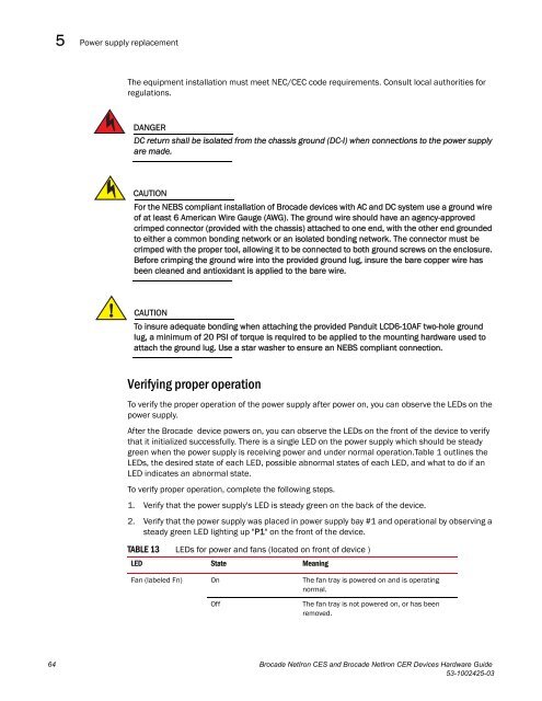
Verifying proper operation<br />
To verify the proper operation of the power supply after power on, you can observe the LEDs on the<br />
power supply.<br />
After the <strong>Brocade</strong> device powers on, you can observe the LEDs on the front of the device to verify<br />
that it initialized successfully. There is a single LED on the power supply which should be steady<br />
green when the power supply is receiving power <strong>and</strong> under normal operation.Table 1 outlines the<br />
LEDs, the desired state of each LED, possible abnormal states of each LED, <strong>and</strong> what to do if an<br />
LED indicates an abnormal state.<br />
To verify proper operation, complete the following steps.<br />
1. Verify that the power supply's LED is steady green on the back of the device.<br />
2. Verify that the power supply was placed in power supply bay #1 <strong>and</strong> operational by observing a<br />
steady green LED lighting up "P1" on the front of the device.<br />
TABLE 13 LEDs for power <strong>and</strong> fans (located on front of device )<br />
LED State Meaning<br />
Fan (labeled Fn) On The fan tray is powered on <strong>and</strong> is operating<br />
normal.<br />
Off The fan tray is not powered on, or has been<br />
removed.<br />
64 <strong>Brocade</strong> NetIron <strong>CES</strong> <strong>and</strong> <strong>Brocade</strong> NetIron <strong>CER</strong> <strong>Devices</strong> <strong>Hardware</strong> Guide<br />
53-1002425-03