- Page 1 and 2: V1.0Programming ManualElektor Proto
- Page 3 and 4: Communications Protocol ...........
- Page 5 and 6: Blok schematic:Bart Huyskens Manual
- Page 7 and 8: Different modules on PCB levelBart
- Page 9 and 10: AVR add-on board• The AVR board h
- Page 11 and 12: Servo moduleSCL-SDAHeadSCL-SDAUS di
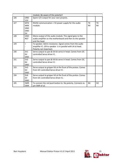
- Page 13: List of all the connectors on the m
- Page 17 and 18: char I2C_RECEIVE_BYTE(char Last);vo
- Page 19 and 20: How to set up Flowcode 4 (PIC) for
- Page 21 and 22: How to set up Flowcode 4 (AVR) for
- Page 23 and 24: How to set op AVRSTUDIO - WINAVR /
- Page 25 and 26: Click on the gear-logo “Edit curr
- Page 27 and 28: Make sure that your fuses tab scree
- Page 29 and 30: How to set up MPLAB - HITECH C Lite
- Page 31 and 32: We choose not to add any file to th
- Page 33 and 34: •Copy paste the “PIC_PROTON_LIB
- Page 35 and 36: Bart Huyskens Manual Elektor Proton
- Page 37 and 38: }{PORTD = 0x0F;__delay_ms(200);PORT
- Page 39 and 40: PIC16F887Demoprogram Flowcode PIC V
- Page 41 and 42: These are 2 normally open push butt
- Page 43 and 44: • After the readbyte instruction
- Page 45 and 46: READ DATA FROM THE SLAVEFor example
- Page 47 and 48: void main(){// init AD & Option reg
- Page 49 and 50: Experience: We use this LCD in I2C
- Page 51 and 52: Commands to write in the command re
- Page 53 and 54: Custom char generatorCustom charact
- Page 55 and 56: The servo motors in the head and th
- Page 57 and 58: This robot can be equipped with up
- Page 59 and 60: Although the signal for the positio
- Page 61 and 62: The head with ldr’s, RGB-led’s
- Page 63 and 64: Head I2C Slave address = 0x10Index
- Page 65 and 66:
Proton robot developer’s notes:Th
- Page 67 and 68:
When a ranging command in cm is giv
- Page 69 and 70:
address of a sonar currently at 0xE
- Page 71 and 72:
The MD25 motor driver moduleThis pr
- Page 73 and 74:
Proton robot developer’s notes:Th
- Page 75 and 76:
The MD25 has 17 registers numbered
- Page 77 and 78:
ultimate speed, the MD25 has a regi
- Page 79 and 80:
Changing the I2C Bus AddressTo chan
- Page 81 and 82:
The line sensor module with 3 IR li
- Page 83 and 84:
Photo of the 3 line follow sensorsT
- Page 85 and 86:
Analogue to digital conversion expl
- Page 87 and 88:
}}Proton robot developer’s notes:
- Page 89 and 90:
RS232 communication explainedRS-232
- Page 91 and 92:
Proton robot developer’s notes:Th
- Page 93 and 94:
• Supportso MMC, SDC, SDHC card f
- Page 95 and 96:
Communications ProtocolDescriptionT
- Page 97 and 98:
Prompt CharacterSetting name: PThis
- Page 99 and 100:
BoostSetting name: BSets the defaul
- Page 101 and 102:
Input/Output Interface SettingsInpu
- Page 103 and 104:
SettingsDescriptionNon-volatile set
- Page 105 and 106:
Play NextDescriptionThis plays the
- Page 107 and 108:
StopDescriptionStops playback.Forma
- Page 109 and 110:
Playback StatusDescriptionThis show
- Page 111 and 112:
Play ToneDescriptionThis command pl
- Page 113 and 114:
Reset AudioDescriptionResets the au
- Page 115 and 116:
Loop CountDescriptionGets or sets t
- Page 117 and 118:
1 1 0001 1 +1.5 dB2 2 0010 2 +3 dB3
- Page 119 and 120:
This command will copy data from an
- Page 121 and 122:
CloseDescriptionCloses an open file
- Page 123 and 124:
Parameters• path is the absolute
- Page 125 and 126:
InfoDescriptionGives the file posit
- Page 127 and 128:
Card InfoDescriptionGets card speci
- Page 129 and 130:
List DirectoryDescriptionThe List D
- Page 131 and 132:
L /PICTURES/*.JPG«sp»----A 2008/0
- Page 133 and 134:
RenameDescriptionRenames/moves a fi
- Page 135 and 136:
O 1 R /LOGS/JANUARY/JAN03.LOGOpen a
- Page 137 and 138:
DescriptionYou can read up to 512 b
- Page 139 and 140:
Read LineDescriptionThe Read Line c
- Page 141 and 142:
WriteDescriptionYou can write up to
- Page 143 and 144:
E /LOG.TXTO 1 RW /LOG.TXTS E0I 10/0
- Page 145 and 146:
Table of SettingsCommunication Sett
- Page 147 and 148:
Input/Output Interface SettingsSett
- Page 149 and 150:
Proton main program for PIC in C:/*
- Page 151 and 152:
void UART_STRING_RECEIVE(char *rece
- Page 153 and 154:
}SSPBUF=Data;//Send bytewhile((PIR1
- Page 155 and 156:
}}// Writes an integer value to the
- Page 157 and 158:
s++;}}//bit STRING_IN( const char *
- Page 159 and 160:
eturn;}}}}}/***********************
- Page 161 and 162:
Proton main program for AVR in C:/*
- Page 163 and 164:
char STR_PREFIX( const char *p, con
- Page 165 and 166:
}TWCR = (1
- Page 167 and 168:
LCD_WRITE_STRING(String);alsoLCD_WR
- Page 169 and 170:
n--;}}//bit char_in( char c, const
- Page 171 and 172:
}} else {_delay_us( 100 );t++;if( t
- Page 173 and 174:
Cheat sheet C - for Hitech C compil
- Page 175:
Version changes summary09/04/2011 v