Morphology and plasmonic properties of self-organized arrays of ...
Morphology and plasmonic properties of self-organized arrays of ...
Morphology and plasmonic properties of self-organized arrays of ...

You also want an ePaper? Increase the reach of your titles
YUMPU automatically turns print PDFs into web optimized ePapers that Google loves.
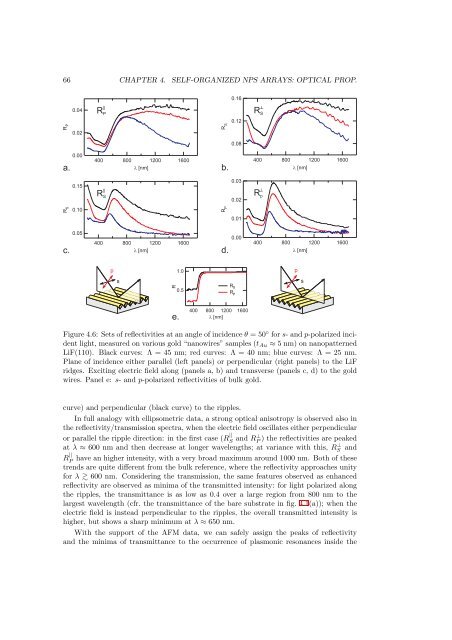
66 CHAPTER 4. SELF-ORGANIZED NPS ARRAYS: OPTICAL PROP.0.16R P0.040.02R P||R S0.12R S┴0.080.0040080012001600a. [nm]b.400800 [nm]120016000.15R S||0.030.02R p┴R S0.10R P0.010.0540080012001600c. [nm]d.0.00400800 [nm]12001600p1.0psR0.5R SR Pse.400800 1200 [nm]1600Figure 4.6: Sets <strong>of</strong> reflectivities at an angle <strong>of</strong> incidence θ = 50 ◦ for s- <strong>and</strong> p-polarized incidentlight, measured on various gold “nanowires” samples (t Au ≈ 5 nm) on nanopatternedLiF(110). Black curves: Λ = 45 nm; red curves: Λ = 40 nm; blue curves: Λ = 25 nm.Plane <strong>of</strong> incidence either parallel (left panels) or perpendicular (right panels) to the LiFridges. Exciting electric field along (panels a, b) <strong>and</strong> transverse (panels c, d) to the goldwires. Panel e: s- <strong>and</strong> p-polarized reflectivities <strong>of</strong> bulk gold.curve) <strong>and</strong> perpendicular (black curve) to the ripples.In full analogy with ellipsometric data, a strong optical anisotropy is observed also inthe reflectivity/transmission spectra, when the electric field oscillates either perpendicularor parallel the ripple direction: in the first case (R ||S <strong>and</strong> R⊥ P ) the reflectivities are peakedat λ ≈ 600 nm <strong>and</strong> then decrease at longer wavelengths; at variance with this, RS ⊥ <strong>and</strong>R || Phave an higher intensity, with a very broad maximum around 1000 nm. Both <strong>of</strong> thesetrends are quite different from the bulk reference, where the reflectivity approaches unityfor λ 600 nm. Considering the transmission, the same features observed as enhancedreflectivity are observed as minima <strong>of</strong> the transmitted intensity: for light polarized alongthe ripples, the transmittance is as low as 0.4 over a large region from 800 nm to thelargest wavelength (cfr. the transmittance <strong>of</strong> the bare substrate in fig. 4.1(a)); when theelectric field is instead perpendicular to the ripples, the overall transmitted intensity ishigher, but shows a sharp minimum at λ ≈ 650 nm.With the support <strong>of</strong> the AFM data, we can safely assign the peaks <strong>of</strong> reflectivity<strong>and</strong> the minima <strong>of</strong> transmittance to the occurrence <strong>of</strong> <strong>plasmonic</strong> resonances inside the