Morphology and plasmonic properties of self-organized arrays of ...
Morphology and plasmonic properties of self-organized arrays of ...
Morphology and plasmonic properties of self-organized arrays of ...

Create successful ePaper yourself
Turn your PDF publications into a flip-book with our unique Google optimized e-Paper software.
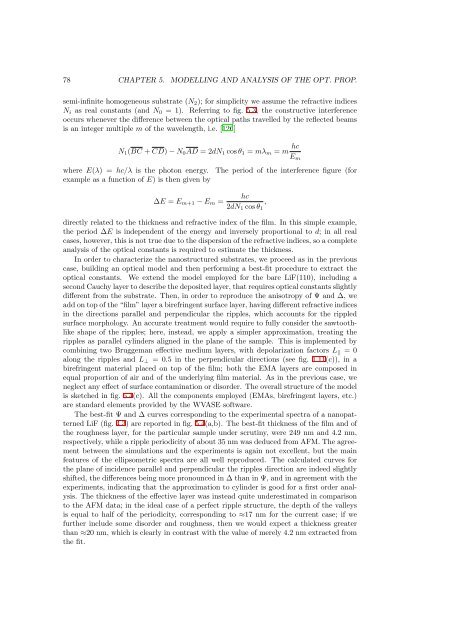
78 CHAPTER 5. MODELLING AND ANALYSIS OF THE OPT. PROP.semi-infinite homogeneous substrate (N 2 ); for simplicity we assume the refractive indicesN i as real constants (<strong>and</strong> N 0 = 1). Referring to fig. 5.3, the constructive interferenceoccurs whenever the difference between the optical paths travelled by the reflected beamsis an integer multiple m <strong>of</strong> the wavelength, i.e. [126]N 1 (BC +CD)−N 0 AD = 2dN 1 cosθ 1 = mλ m = m hcE mwhere E(λ) = hc/λ is the photon energy. The period <strong>of</strong> the interference figure (forexample as a function <strong>of</strong> E) is then given by∆E = E m+1 −E m =hc2dN 1 cosθ 1,directly related to the thickness <strong>and</strong> refractive index <strong>of</strong> the film. In this simple example,the period ∆E is independent <strong>of</strong> the energy <strong>and</strong> inversely proportional to d; in all realcases, however, this is not true due to the dispersion <strong>of</strong> the refractive indices, so a completeanalysis <strong>of</strong> the optical constants is required to estimate the thickness.In order to characterize the nanostructured substrates, we proceed as in the previouscase, building an optical model <strong>and</strong> then performing a best-fit procedure to extract theoptical constants. We extend the model employed for the bare LiF(110), including asecondCauchylayertodescribethedepositedlayer, thatrequiresopticalconstantsslightlydifferent from the substrate. Then, in order to reproduce the anisotropy <strong>of</strong> Ψ <strong>and</strong> ∆, weaddontop<strong>of</strong>the“film”layerabirefringentsurfacelayer, havingdifferentrefractiveindicesin the directions parallel <strong>and</strong> perpendicular the ripples, which accounts for the rippledsurface morphology. An accurate treatment would require to fully consider the sawtoothlikeshape <strong>of</strong> the ripples; here, instead, we apply a simpler approximation, treating theripples as parallel cylinders aligned in the plane <strong>of</strong> the sample. This is implemented bycombining two Bruggeman effective medium layers, with depolarization factors L || = 0along the ripples <strong>and</strong> L ⊥ = 0.5 in the perpendicular directions (see fig. 1.11(c)), in abirefringent material placed on top <strong>of</strong> the film; both the EMA layers are composed inequal proportion <strong>of</strong> air <strong>and</strong> <strong>of</strong> the underlying film material. As in the previous case, weneglect any effect <strong>of</strong> surface contamination or disorder. The overall structure <strong>of</strong> the modelis sketched in fig. 5.4(c). All the components employed (EMAs, birefringent layers, etc.)are st<strong>and</strong>ard elements provided by the WVASE s<strong>of</strong>tware.The best-fit Ψ <strong>and</strong> ∆ curves corresponding to the experimental spectra <strong>of</strong> a nanopatternedLiF (fig. 4.3) are reported in fig. 5.4(a,b). The best-fit thickness <strong>of</strong> the film <strong>and</strong> <strong>of</strong>the roughness layer, for the particular sample under scrutiny, were 249 nm <strong>and</strong> 4.2 nm,respectively, while a ripple periodicity <strong>of</strong> about 35 nm was deduced from AFM. The agreementbetween the simulations <strong>and</strong> the experiments is again not excellent, but the mainfeatures <strong>of</strong> the ellipsometric spectra are all well reproduced. The calculated curves forthe plane <strong>of</strong> incidence parallel <strong>and</strong> perpendicular the ripples direction are indeed slightlyshifted, the differences being more pronounced in ∆ than in Ψ, <strong>and</strong> in agreement with theexperiments, indicating that the approximation to cylinder is good for a first order analysis.The thickness <strong>of</strong> the effective layer was instead quite underestimated in comparisonto the AFM data; in the ideal case <strong>of</strong> a perfect ripple structure, the depth <strong>of</strong> the valleysis equal to half <strong>of</strong> the periodicity, corresponding to ≈17 nm for the current case; if wefurther include some disorder <strong>and</strong> roughness, then we would expect a thickness greaterthan ≈20 nm, which is clearly in contrast with the value <strong>of</strong> merely 4.2 nm extracted fromthe fit.