TRS Star CompactFlash Card Industrial-Grade Datasheet
TRS Star CompactFlash Card Industrial-Grade Datasheet
TRS Star CompactFlash Card Industrial-Grade Datasheet
- No tags were found...

You also want an ePaper? Increase the reach of your titles
YUMPU automatically turns print PDFs into web optimized ePapers that Google loves.
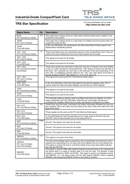
<strong>Industrial</strong>-<strong>Grade</strong> <strong>CompactFlash</strong> <strong>Card</strong><strong>TRS</strong> <strong>Star</strong> SpecificationFor more information visit us under:http://www.trs-star.comSignal Name Dir. DescriptionBVD2(PC <strong>Card</strong> Memory Mode)-SPKR(PC <strong>Card</strong> I/O Mode)-DASP(True IDE Mode)-CD1, -CD2(PC <strong>Card</strong> Memory Mode)-CD1, -CD2(PC <strong>Card</strong> I/O Mode)-CD1, -CD2(True IDE Mode)-CE1, -CE2(PC <strong>Card</strong> Memory Mode)<strong>Card</strong> Enable-CE1, -CE2(PC <strong>Card</strong> I/O Mode)<strong>Card</strong> Enable-CS0, -CS1(True IDE Mode)-CSEL(PC <strong>Card</strong> Memory Mode).-CSEL(PC <strong>Card</strong> I/O Mode)-CSEL(True IDE Mode)D00—D15(PC <strong>Card</strong> Memory Mode)D00—D15(PC <strong>Card</strong> I/O Mode)D00—D15(True IDE Mode)GND(PC <strong>Card</strong> Memory Mode)GND(PC <strong>Card</strong> I/O Mode)GND(True IDE Mode)-INPACK(PC <strong>Card</strong> Memory Mode)-INPACK(PC <strong>Card</strong> I/O Mode)Input AcknowledgeDMARQ1(True IDE Mode)I/OOIII/OPWROThis output line is always driven to a high state in Memory Mode since a battery is notrequired for this product.This output line is always driven to a high state in I/O Mode since this product does notsupport the audio function.In the True IDE Mode, this input/output is the Disk Active/Slave Present signal in theMaster/Slave handshake protocol.These <strong>Card</strong> Detect pins are connected to ground on the <strong>CompactFlash</strong> <strong>Card</strong>. They areused by the host to determine if the card is fully inserted into its socket.This signal is the same for all modes.This signal is the same for all modes.These input signals are used both to select the card and to indicate to the card whethera byte or a word operation is being performed. -CE2 always accesses the odd byte ofthe word. -CE1 accesses the even byte or the Odd byte of the word depending on A0and -CE2. A multiplexing scheme based on A0, -CE1, and -CE2 allows 8 bit hosts toaccess all data on D0-D7. See Tables 3-11, 3-12, 3-15, and 3-16.This signal is the same as the PC <strong>Card</strong> Memory Mode signal.In the True IDE Mode -CS0 is the chip select for the task file registers while -CS1 isused to select the Alternate Status Register and the Device Control Register.This signal is not used for this mode.This signal is not used for this mode.This internally pulled up signal is used to configure this device as a Master or a Slavewhen configured in the True IDE Mode. When this pin is grounded, this device isconfigured as a Master. When the pin is open, this device is configured as a Slave.These lines carry the Data, Commands and Status information between the host andthe controller. D00 is the LSB of the Even Byte of the Word. D08 is the LSB of the OddByte of the Word.These signals are the same as the PC <strong>Card</strong> Memory Mode signal.In True IDE Mode all Task File operations occur in byte mode on the low order busD00-D07 while all data transfers are 16 bits using D00-D15.Ground. This signal is the same for all modes.Ground. This signal is the same for all modes.Ground. This signal is the same for all modes.This signal is not used in this mode.The Input Acknowledge signal is asserted by the <strong>CompactFlash</strong> <strong>Card</strong> when the card isselected and responding to an I/O read cycle at the address that is on the address bus.This signal is used by the host to control the enable of any input data buffers betweenthe card and the CPU.This signal is used for DMA data transfers between host and device and is asserted bythe device when it is ready to transfer data to or from the host. The direction of datatransfer is controlled by DIOR- and DIOW-. This signal is used in a handshake mannerwith DMACK- (i.e., the device waits until the host asserts DMACK- before negatingDMARQ, and reasserting DMARQ if there is more data to transfer).<strong>TRS</strong>* Tele-Radio-Space GmbH, reserves the right Page 18 from 113 <strong>Industrial</strong>-<strong>Grade</strong> <strong>CompactFlash</strong> <strong>Card</strong>to change products or specifications without notice. Rev. 1.4 Stand 06/2006