TRS Star CompactFlash Card Industrial-Grade Datasheet
TRS Star CompactFlash Card Industrial-Grade Datasheet
TRS Star CompactFlash Card Industrial-Grade Datasheet
- No tags were found...

You also want an ePaper? Increase the reach of your titles
YUMPU automatically turns print PDFs into web optimized ePapers that Google loves.
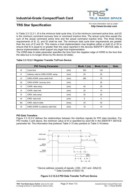
<strong>Industrial</strong>-<strong>Grade</strong> <strong>CompactFlash</strong> <strong>Card</strong><strong>TRS</strong> <strong>Star</strong> SpecificationFor more information visit us under:http://www.trs-star.comIn Table 3.3.12.2-1, t0 is the minimum total cycle time, t2 is the minimum command active time, and t2iis the minimum command recovery time or command inactive time. The actual cycle time equals thesum of the actual command active time and the actual command inactive time. The three timingrequirements of t0, t2, and t2i shall be met. The minimum total cycle time requirements are greaterthan the sum of t2 and t2i. This means a host implementation may lengthen either or both t2 or t2i toensure that t0 is equal to or greater than the value reported in the devices IDENTIFY DEVICE data. Adevice implementation shall support any legal host implementation.The IORD-data tri-state parameter specifies the time from the negation edge of /IORD to the time thatthe data bus is no longer driven by the device (tri-state).Table 3.3.12.2-1 Register Transfer To/From DevicePIO Timing Parameter Mode 1 (ns) Mode 4 (ns) Notet0 Cycle time {min} 383 120t1 Address valid to IORD-/IOWR- setup {min} 50 25t2 IORD-/IOWR- pulse width 8-bit {min} 290 70t2i IORD-/IOWR- recovery time {min} - 25t3 IOWR- data setup {min} 45 20t4 IOWR- data hold {min} 20 10t5 IORD- data setup {min} 35 20t6 IORD- data hold {min} 5 5t6z IORD- data tri-state {max} 30 30t9 IORD-/IOWR- to address valid hold {min} 15 10PIO Data TransfersFigure 3.3.12.2-2 defines the relationships between the interface signals for PIO data transfers. ForPIO modes 3 and above, the minimum value of t0 is specified by word 68 in the IDENTIFY DEVICEparameter list. The information that prefaces Table 3-15 also pertains to Table 3-16 below.* Device address consists of signals –CS0, -CS1 and –DA(2:0)** Data Consists of DD(0:15)Figure 3.3.12.2-2 PIO Data Transfer To/From Device<strong>TRS</strong>* Tele-Radio-Space GmbH, reserves the right Page 31 from 113 <strong>Industrial</strong>-<strong>Grade</strong> <strong>CompactFlash</strong> <strong>Card</strong>to change products or specifications without notice. Rev. 1.4 Stand 06/2006