36 Drying of Wood
36 Drying of Wood
36 Drying of Wood
- No tags were found...

Create successful ePaper yourself
Turn your PDF publications into a flip-book with our unique Google optimized e-Paper software.
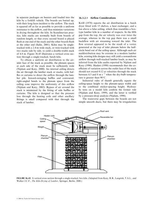
in separate packages on bearers and loaded into thekiln by a forklift vehicle. The boards are butted up,with their long faces incident to the airflow. The stackis squared <strong>of</strong>f as far as possible to provide a uniformresistance to the airflow, and thus minimize variationsin drying throughout the kiln. In Scandinavian practice,kiln stacks are normally built from boards <strong>of</strong>random length, so that every second board is placedflush at one end <strong>of</strong> the stack and the other boards flushat the other end (Salin, 2001). Kilns may be singletrackedwith a 2.4-m wide stack, or twin-tracked withtwo stacks side by side, to yield a double-width stack<strong>of</strong> 4.8 m. Figure <strong>36</strong>.45 illustrates a vertical cross sectionthrough a single-tracked, batch kiln.To obtain a uniform air distribution to the airinletface <strong>of</strong> the stack as possible, the plenum spacesat each side <strong>of</strong> the stack must be sufficiently wide(Nijdam and Keey, 2000). An internal ceiling directsthe air through the lumber stack or stacks, with bafflesor curtains to direct the airflow through the lumberpile. Inward-swinging baffles and contoured,right-angled bends to the plenum space from theceiling zone improve the uniformity <strong>of</strong> this airflow(Nijdam and Keey, 2002). Bypass <strong>of</strong> air around thestack is minimized by the fitting <strong>of</strong> side baffles orcurtains. The kiln is designed so that the pressureloss through the heating coils and other ancillaryfittings is small compared with that through thestack <strong>of</strong> lumber.<strong>36</strong>.3.2.1 Airflow ConsiderationsKröll (1978) reports the air distribution in a batchdryer fitted with 15 shelves, a heat exchanger, and afan above a false ceiling, which thus resembles a boxtypelumber kiln in a number <strong>of</strong> respects. In the fifthgap from the top, the air velocity was over twice theaverage, whereas in the top gap there was a smallbackflow with air streaming toward the inlet. Theflow reversal appeared to be the result <strong>of</strong> a vortexgenerated at the top <strong>of</strong> inlet plenum below the halfcirclebend out <strong>of</strong> the ceiling space. Although such airmaldistribution may be extreme in a modern lumberkiln, existing kiln designs may still yield a nonuniformairflow through well-stacked lumber loads, as may beinferred from the kiln audits reported by Nijdam andKeey (1996). Haslett (1998) recommends that the coefficient<strong>of</strong> variation across the outlet face <strong>of</strong> the stackshould not exceed 0.12 at velocities through the stackbetween 4.5 and 8 m s 1 when the dry-bulb temperatureis greater than 908C.Industrial rules <strong>of</strong> thumb generally equate theceiling-space height to the plenum-space width andto the combined sticker-spacing height. Hydraulictests on a model kiln confirm the former rule(Nijdam and Keey, 1999), and the latter is verifiedby a pressure-drop analysis (Nijdam, 1998).The transverse gaps between the boards are notsimple smooth ducts, but there may be irregularitiesRo<strong>of</strong> ventHeater coilsCeilingspaceReversible fanWeightPlenumchamberPlenumchamberFilletFIGURE <strong>36</strong>.45 A vertical cross section through a single-tracked, box kiln. (Adapted from Keey, R.B., Langrish, T.A.L., andWalker J.C.F., The Kiln-<strong>Drying</strong> <strong>of</strong> Lumber, Springer, Berlin, 2000.)ß 2006 by Taylor & Francis Group, LLC.