Hydraulic cylinder Tie Rod Design - imperial - Duncan Rogers
Hydraulic cylinder Tie Rod Design - imperial - Duncan Rogers
Hydraulic cylinder Tie Rod Design - imperial - Duncan Rogers

You also want an ePaper? Increase the reach of your titles
YUMPU automatically turns print PDFs into web optimized ePapers that Google loves.
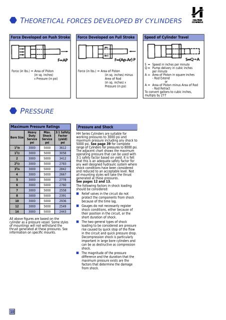
THEORETICAL FORCES DEVELOPED BY CYLINDERSForce Developed on Push Stroke Force Developed on Pull Stroke Speed of Cylinder TravelForce (in lbs.) = Area of Piston(in sq. inches)x Pressure (in psi)Force (in lbs.) = Area of Piston(in sq. inches) minusArea of <strong>Rod</strong>(in sq. inches) xPressure (in psi)S = Speed in inches per minuteQ = Pump delivery in cubic inchesper minuteA = Area of Piston in square inches- <strong>Rod</strong> ExtendorA = Area of Piston minus Area of <strong>Rod</strong>- <strong>Rod</strong> RetractTo convert gallons to cubic inches,multiply by 277PR E SS U R EMaximum Pressure RatingsBore Size1 1 /81 1 /222 1 /23 1 /445678101214HeavyDutyServicepsi3000300030003000300030003000300030003000300030003000Max.ShockServicepsi50005000500050005000500050005000500050005000500050003:1 SafetyFactor(yield)psi3612305834122783284226672778276025582391293625492443All above figures are based on the<strong>cylinder</strong> as a pressure vessel. Some stylesof mountings will not withstand thethrust generated at these pressures. Seeinformation on specific mounts.Pressure and ShockHH Series Cylinders are suitable forworking pressures to 3000 psi andmaximum pressure including any shock to5000 psi. See page 39 for completerange of Cylinders for pressures to 8000 psi.The adjacent chart shows the maximumoperating pressure that can be used with3:1 safety factor based on yield. It is feltthat this is an adequate safety factor forany well designed hydraulic system whereshock conditions have been consideredand reduced to an acceptable level. Notall mounting styles will take the thrustgenerated at these pressures.See pages 12 and 13.The following factors in shock loadingshould be considered:■ Relief valves in the circuit do notprotect the components from shockbecause of the time lag.■ Gauges do not necessarily registershock conditions, either because oftheir position in the circuit, or theshort duration of shock.■ The two general types of shockloading to be considered are pressurerise caused by quick stop of the flowin the circuit and quick pressure drop.Decompression shock is particularlyimportant in large bore <strong>cylinder</strong>s andcan be as destructive as compressionshock.■ The magnitude of the pressuredifference and the duration that themaximum pressure exists are thefactors that determine the damagefrom shock.10