Hydraulic cylinder Tie Rod Design - imperial - Duncan Rogers
Hydraulic cylinder Tie Rod Design - imperial - Duncan Rogers
Hydraulic cylinder Tie Rod Design - imperial - Duncan Rogers

Create successful ePaper yourself
Turn your PDF publications into a flip-book with our unique Google optimized e-Paper software.
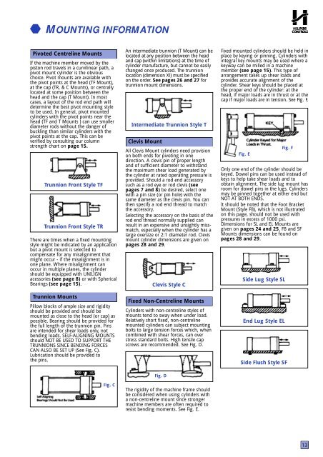
MOUNTING INFORMATIONPivoted Centreline MountsIf the machine member moved by thepiston rod travels in a curvilinear path, apivot mount <strong>cylinder</strong> is the obviouschoice. Pivot mounts are available withthe pivot points at the head (TF Mount),at the cap (TR, & C Mounts), or centrallylocated at some position between thehead and the cap (T Mount). In mostcases, a layout of the rod end path willdetermine the best pivot mounting styleto be used. In general, pivot mounted<strong>cylinder</strong>s with the pivot points near thehead (TF and T Mounts ) can use smallerdiameter rods without the danger ofbuckling than similar <strong>cylinder</strong>s with thepivot points at the cap. This can beverified by consulting our columnstrength chart on page 15.Trunnion Front Style TFTrunnion Front Style TRThere are times when a fixed mountingstyle might be indicated by an applicationbut a pivot mount is selected tocompensate for any misalignment thatmight occur - if the misalignment is inone plane. Where misalignment canoccur in multiple planes, the <strong>cylinder</strong>should be equipped with UNILIGNacessories (see page 8) or with SphericalBearings (see page 15).Trunnion MountsPillow blocks of ample size and rigidityshould be provided and should bemounted as close to the head (or cap) aspossible. Bearing should be provided forthe full length of the trunnion pin. Pinsare intended for shear loads only, notbending loads. SELF-ALIGNING MOUNTSshould NOT BE USED TO SUPPORT THETRUNNIONS SINCE BENDING FORCESCAN ALSO BE SET UP (See Fig. C).Lubrication should be provided tothe pins.An intermediate trunnion (T Mount) can belocated at any position between the headand cap (within limitations) at the time of<strong>cylinder</strong> manufacture, but cannot be easilychanged once produced. The trunnionlocation (dimension Xl) must be specifie don the order. See pages 26 and 27 f o rtrunnion mount dimensions.Intermediate Trunnion Style TClevis MountAll Clevis Mount <strong>cylinder</strong>s need provisionon both ends for pivoting in onedirection. A clevis pin of proper lengthand of sufficient diameter to withstandthe maximum shear load generated bythe <strong>cylinder</strong> at rated operating pressure isprovided. Should a rod end accessorysuch as a rod eye or rod clevis (seepages 7 and 8) be desired, select onewith a pin size (or pin hole) with thesame diameter as the clevis pin. You canthen specify a rod end thread to matchthe accessory.Selecting the accessory on the basis of therod end thread normally supplied canresult in an expensive and unsightly missmatch,especially when the <strong>cylinder</strong> has alarge oversize or 2:1 diameter rod. Clevismount <strong>cylinder</strong> dimensions are given onpages 28 and 29.Clevis Style CFixed Non-Centreline MountsCylinders with non-centreline styles ofmounts tend to sway when under load.Relatively short fixed, non-centrelinemounted <strong>cylinder</strong>s can subject mountingbolts to large tension forces which, whencombined with shear forces, can overstress standard bolts. High tensile capscrews are recommended. See Fig. D.Fixed mounted <strong>cylinder</strong>s should be held inplace by keying or pinning. Cylinders withintegral key mounts may be used where akeyway can be milled in a machinemember (see page 15). This type ofarrangement takes up shear loads andprovides accurate alignment of the<strong>cylinder</strong>. Shear keys should be placed atthe proper end of the <strong>cylinder</strong>: at thehead, if major loads are in thrust or at thecap if major loads are in tension. See Fig. F.Fig. EFig. FOnly one end of the <strong>cylinder</strong> should bekeyed. Dowel pins can be used instead ofkeys to help take shear loads and toobtain alignment. The side lug mount hasroom for dowel pins in the lugs. Cylindersmay be pinned together at either end butNOT AT BOTH ENDS.It should be noted that the Foot BracketMount (Style FB), which is not illustratedon this page, should not be used withpressures in excess of 1000 psi.Dimensions for SL and EL Mounts aregiven on pages 24 and 25. FB and SFMounts dimensions can be found onpages 28 and 29.Side Lug Style SLEnd Lug Style ELSide Flush Style SFFig. CFig. DThe rigidity of the machine frame shouldbe considered when using <strong>cylinder</strong>s witha non-centreline mount since strongermachine members are often required toresist bending moments. See Fig. E.13