Hydraulic cylinder Tie Rod Design - imperial - Duncan Rogers
Hydraulic cylinder Tie Rod Design - imperial - Duncan Rogers
Hydraulic cylinder Tie Rod Design - imperial - Duncan Rogers

You also want an ePaper? Increase the reach of your titles
YUMPU automatically turns print PDFs into web optimized ePapers that Google loves.
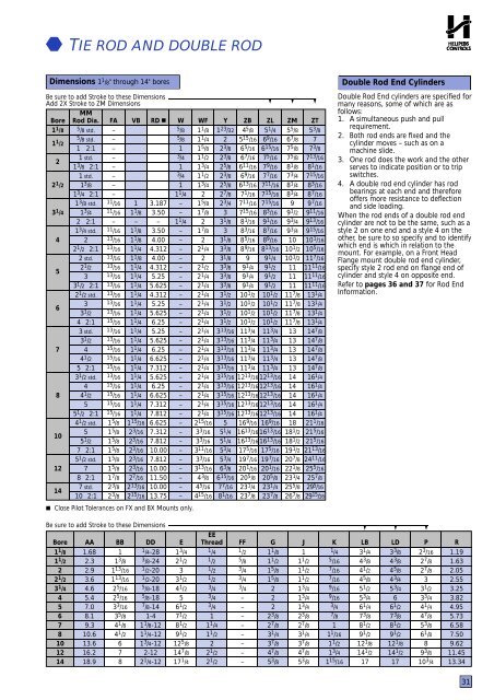
TIE ROD AND DOUBLE RODDimensions 1 1 /8" through 14" boresBe sure to add Stroke to these DimensionsAdd 2X Stroke to ZM Dimensions▼ ▼ ▼MMBore <strong>Rod</strong> Dia. FA VB RD ■ W WF Y ZB ZL ZM ZT1 1 /8 5 /8 std. –5 /8 1 1 /8 1 23 /32 4 5 /8 5 1 /4 5 5 /8 5 3 /81 1 /25 /8 std. –/8 1 1 /4 2 5 15 /16 6 9 /16 6 7 /8 71 2:1 –1 1 5 /8 2 3 /8 6 5 /16 6 15 /16 7 5 /8 7 3 /821 std. –/4 1 1 /2 2 3 /8 6 7 /16 7 5 /16 7 5 /8 7 13 /161 3 /8 2:1 –1 1 3 /4 2 5 /8 6 11 /16 7 9 /16 8 1 /8 8 1 /161 std. –3 /4 1 1 /2 2 3 /8 6 9 /16 7 7 /16 7 3 /4 7 15 /162 1 /2 1 3 /8 –1 1 3 /4 2 5 /8 6 13 /16 7 11 /16 8 1 /4 8 3 /161 3 /4 2:1 –1 1 /4 2 2 7 /8 7 1 /16 7 15 /16 8 3 /4 8 7 /161 3 /8 std. 11 /16 1 3.187 – 1 5 /8 2 3 /4 7 11 /16 7 15 /16 9 9 7 /163 1 /4 1 3 /4 11 /16 1 1 /8 3.50 – 1 7 /8 3 7 15 /16 8 3 /16 9 1 /2 9 11 /162 2:1 – – – 1 1 /4 2 3 1 /8 8 1 /16 9 1 /16 9 3 /4 9 13 /161 3 /4 std. 11 /16 1 1 /8 3.50 – 1 7 /8 3 8 3 /16 8 7 /16 9 3 /4 9 15 /164 2 13 /16 1 1 /8 4.00 – 2 3 1 /8 8 5 /16 8 9 /16 10 10 1 /162 1 /2 2:1 13 /16 1 1 /4 4.312 – 2 1 /4 3 3 /8 8 9 /16 8 13 /16 10 1 /2 10 5 /162 std. 13 /16 1 1 /8 4.00 – 2 3 1 /8 9 9 1 /4 10 1 /2 11 7 /1652 1 /2 /16 1 1 /4 4.312 – 2 1 /2 3 3 /8 9 1 /4 9 1 /2 11 11 11 /163 /16 1 1 /4 5.25 – 2 1 /4 3 3 /8 9 1 /4 9 1 /2 11 11 11 /163 1 /2 2:1 13 /16 1 1 /4 5.625 – 2 1 /4 3 3 /8 9 1 /4 9 1 /2 11 11 11 /162 1 /2 std. 13 /16 1 1 /4 4.312 – 2 1 /4 3 1 /2 10 1 /2 10 1 /2 11 7 /8 13 1 /463 /16 1 1 /4 5.25 – 2 1 /4 3 1 /2 10 1 /2 10 1 /2 11 7 /8 13 1 /43 1 /2 /16 1 1 /4 5.625 – 2 1 /4 3 1 /2 10 1 /2 10 1 /2 11 7 /8 13 1 /44 2:1 15 /16 1 1 /4 6.25 – 2 1 /4 3 1 /2 10 1 /2 10 1 /2 11 7 /8 13 1 /43 std. 13 /16 1 1 /4 5.25 – 2 1 /4 3 13 /16 11 3 /4 11 3 /4 13 14 7 /83 1 /2 13 /16 1 1 /4 5.625 – 2 1 /4 3 13 /16 11 3 /4 11 3 /4 13 14 7 /87 4 15 /16 1 1 /4 6.25 – 2 1 /4 3 13 /16 11 3 /4 11 3 /4 13 14 7 /84 1 /2 15 /16 1 1 /4 6.625 – 2 1 /4 3 13 /16 11 3 /4 11 3 /4 13 14 7 /85 2:1 15 /16 1 1 /4 7.312 – 2 1 /4 3 13 /16 11 3 /4 11 3 /4 13 14 7 /83 1 /2 std. 13 /16 1 1 /4 5.625 – 2 1 /4 3 15 /16 12 13 /16 12 13 /16 14 16 1 /44 15 /16 1 1 /4 6.25 – 2 1 /4 3 15 /16 12 13 /16 12 13 /16 14 16 1 /48 4 1 /2 15 /16 1 1 /4 6.625 – 2 1 /4 3 15 /16 12 13 /16 12 13 /16 14 16 1 /45 15 /16 1 1 /4 7.312 – 2 1 /4 3 15 /16 12 13 /16 12 13 /16 14 16 1 /45 1 /2 2:1 15 /16 1 1 /4 7.812 – 2 1 /4 3 15 /16 12 13 /16 12 13 /16 14 16 1 /44 1 /2 std. 1 5 /8 1 15 /16 6.625 – 2 15 /16 5 16 9 /16 16 9 /16 18 21 1 /16105 1 5 /8 2 3 /16 7.312 – 3 3 /16 5 1 /4 16 13 /16 16 13 /16 18 1 /2 21 5 /165 1 /2 1 5 /8 2 3 /16 7.812 – 3 3 /16 5 1 /4 16 13 /16 16 13 /16 18 1 /2 21 5 /167 2:1 1 5 /8 2 3 /16 10.00 – 3 11 /16 5 3 /4 17 5 /16 17 5 /16 19 1 /2 21 13 /165 1 /2 std. 1 5 /8 2 3 /16 7.812 – 3 3 /16 5 3 /4 19 7 /16 19 7 /16 20 7 /8 24 11 /1612 7 1 5 /8 2 3 /16 10.00 – 3 13 /16 6 3 /8 20 1 /16 20 1 /16 22 1 /8 25 5 /168 2:1 1 7 /8 2 7 /16 11.50 – 4 3 /8 6 15 /16 20 5 /8 20 5 /8 23 1 /4 25 7 /8147 std. 2 3 /8 2 13 /16 10.00 – 4 5 /16 7 7 /16 23 1 /4 23 1 /4 25 5 /8 29 5 /1610 2:1 2 3 /8 2 15 /16 13.75 – 4 15 /16 8 1 /16 23 7 /8 23 7 /8 26 7 /8 29 15 /1 6 Close Pilot Tolerances on FX and BX Mounts only.Double <strong>Rod</strong> End CylindersDouble <strong>Rod</strong> End <strong>cylinder</strong>s are specified formany reasons, some of which are asfollows:1. A simultaneous push and pullrequirement.2. Both rod ends are fixed and the<strong>cylinder</strong> moves – such as on amachine slide.3. One rod does the work and the otherserves to indicate position or to tripswitches.4. A double rod end <strong>cylinder</strong> has rodbearings at each end and thereforeoffers more resistance to deflectionand side loading.When the rod ends of a double rod end<strong>cylinder</strong> are not to be the same, such as astyle 2 on one end and a style 4 on theother, be sure to so specify and to identifywhich end is which in relation to themount. For example, on a Front HeadFlange mount double rod end <strong>cylinder</strong>,specify style 2 rod end on flange end of<strong>cylinder</strong> and style 4 on opposite end.Refer to pages 36 and 37 for <strong>Rod</strong> EndInformation.Be sure to add Stroke to these Dimensions ▼ ▼ ▼EEBore AA BB DD E Thread FF G J K LB LD P R1 1 /8 1.68 1 1 /4-28 1 3 /4 1 /4 1 /2 1 1 /8 1 1 /4 3 1 /4 3 3 /8 2 3 /16 1.191 1 /2 2.3 1 3 /8 3 /8-24 2 1 /2 1 /2 5 /8 1 1 /2 1 1 /2 5 /16 4 3 /8 4 3 /8 2 7 /8 1.632 2.9 1 13 /16 1 /2-20 3 1 /2 3 /4 1 5 /8 1 1 /2 7 /16 4 1 /2 4 5 /8 2 7 /8 2.052 1 /2 3.6 1 13 /16 1 /2-20 3 1 /2 1 /2 3 /4 1 5 /8 1 1 /2 7 /16 4 5 /8 4 3 /4 3 2.553 1 /4 4.6 2 5 /16 5 /8-18 4 1 /2 3 /4 3 /4 2 1 3 /4 9 /16 5 1 /2 5 3 /4 3 1 /2 3.254 5.4 2 5 /16 5 /8-18 5 3 /4 – 2 1 3 /4 9 /16 5 3 /4 6 3 3 /4 3.825 7.0 3 3 /16 7 /8-14 6 1 /2 3 /4 – 2 1 3 /4 3 /4 6 1 /4 6 1 /2 4 1 /4 4.956 8.1 3 5 /8 1-4 7 1 /2 1 – 2 3 /8 2 3 /8 7 /8 7 3 /8 7 3 /8 4 7 /8 5.737 9.3 4 1 /8 1 1 /8-12 8 1 /2 1 1 /4 – 2 7 /8 2 7 /8 1 8 1 /2 8 1 /2 5 3 /8 6.588 10.6 4 1 /2 1 1 /4-12 9 1 /2 1 1 /2 – 3 1 /4 3 1 /4 1 1 /16 9 1 /2 9 1 /2 6 1 /8 7.5010 13.6 6 1 3 /4-12 12 5 /8 2 – 3 7 /8 3 7 /8 1 1 /2 12 1 /8 12 1 /8 8 9.6212 16.2 7 2-12 14 7 /8 2 1 /2 – 4 7 /8 4 7 /8 1 3 /4 14 1 /2 14 1 /2 9 3 /8 11.4514 18.9 8 2 1 /4-12 17 1 /4 2 1 /2 – 5 3 /8 5 3 /8 1 15 /16 17 17 10 3 /4 13.3431