Hydraulic cylinder Tie Rod Design - imperial - Duncan Rogers
Hydraulic cylinder Tie Rod Design - imperial - Duncan Rogers
Hydraulic cylinder Tie Rod Design - imperial - Duncan Rogers

Create successful ePaper yourself
Turn your PDF publications into a flip-book with our unique Google optimized e-Paper software.
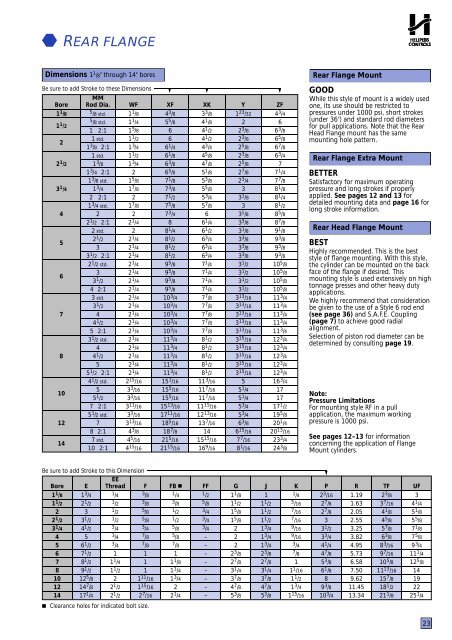
REAR FLANGEDimensions 1 1 /8" through 14" boresBe sure to add Stroke to these Dimensions ▼ ▼ ▼MMBore <strong>Rod</strong> Dia. WF XF XK Y ZF1 1 /8 5 /8 std. 1 1 /8 4 3 /8 3 3 /8 1 23 /32 4 3 /41 1 /25 /8 std. 1 1 /4 5 5 /8 4 1 /8 2 61 2:1 1 5 /8 6 4 1 /2 2 3 /8 6 3 /821 std. 1 1 /2 6 4 1 /2 2 3 /8 6 5 /81 3 /8 2:1 1 3 /4 6 1 /4 4 3 /4 2 5 /8 6 7 /81 std. 1 1 /2 6 1 /8 4 5 /8 2 3 /8 6 3 /42 1 /2 1 3 /8 1 3 /4 6 3 /8 4 7 /8 2 5 /8 71 3 /4 2:1 2 6 5 /8 5 1 /8 2 7 /8 7 1 /41 3 /8 std. 1 5 /8 7 1 /8 5 3 /8 2 3 /4 7 7 /83 1 /4 1 3 /4 1 7 /8 7 3 /8 5 5 /8 3 8 1 /82 2:1 2 7 1 /2 5 3 /4 3 1 /8 8 1 /41 3 /4 std. 1 7 /8 7 5 /8 5 7 /8 3 8 1 /24 2 2 7 3 /4 6 3 1 /8 8 5 /82 1 /2 2:1 2 1 /4 8 6 1 /4 3 3 /8 8 7 /82 std. 2 8 1 /4 6 1 /2 3 1 /8 9 1 /852 1 /2 2 1 /4 8 1 /2 6 3 /4 3 3 /8 9 3 /83 2 1 /4 8 1 /2 6 3 /4 3 3 /8 9 3 /83 1 /2 2:1 2 1 /4 8 1 /2 6 3 /4 3 3 /8 9 3 /82 1 /2 std. 2 1 /4 9 5 /8 7 1 /4 3 1 /2 10 5 /863 2 1 /4 9 5 /8 7 1 /4 3 1 /2 10 5 /83 1 /2 2 1 /4 9 5 /8 7 1 /4 3 1 /2 10 5 /84 2:1 2 1 /4 9 5 /8 7 1 /4 3 1 /2 10 5 /83 std. 2 1 /4 10 3 /4 7 7 /8 3 13 /16 11 3 /43 1 /2 2 1 /4 10 3 /4 7 7 /8 3 13 /16 11 3 /47 4 2 1 /4 10 3 /4 7 7 /8 3 13 /16 11 3 /44 1 /2 2 1 /4 10 3 /4 7 7 /8 3 13 /16 11 3 /45 2:1 2 1 /4 10 3 /4 7 7 /8 3 13 /16 11 3 /43 1 /2 std. 2 1 /4 11 3 /4 8 1 /2 3 15 /16 12 3 /44 2 1 /4 11 3 /4 8 1 /2 3 15 /16 12 3 /48 4 1 /2 2 1 /4 11 3 /4 8 1 /2 3 15 /16 12 3 /45 2 1 /4 11 3 /4 8 1 /2 3 15 /16 12 3 /45 1 /2 2:1 2 1 /4 11 3 /4 8 1 /2 3 15 /16 12 3 /44 1 /2 std. 2 15 /16 15 1 /16 11 3 /16 5 16 3 /4105 3 3 /16 15 5 /16 11 7 /16 5 1 /4 175 1 /2 3 3 /16 15 5 /16 11 7 /16 5 1 /4 177 2:1 3 11 /16 15 13 /16 11 15 /16 5 3 /4 17 1 /25 1 /2 std. 3 3 /16 17 11 /16 12 13 /16 5 3 /4 19 5 /812 7 3 13 /16 18 5 /16 13 7 /16 6 3 /8 20 1 /48 2:1 4 3 /8 18 7 /8 14 6 15 /16 20 13 /16147 std. 4 5 /16 21 5 /16 15 15 /16 7 7 /16 23 3 /410 2:1 4 15 /16 21 15 /16 16 9 /16 8 1 /16 24 3 /8Rear Flange MountGOODWhile this style of mount is a widely usedone, its use should be restricted topressures under 1000 psi, short strokes(under 36") and standard rod diametersfor pull applications. Note that the RearHead Flange mount has the samemounting hole pattern.Rear Flange Extra MountBETTERSatisfactory for maximum operatingpressure and long strokes if properlyapplied. See pages 12 and 13 fordetailed mounting data and page 16 forlong stroke information.Rear Head Flange MountBESTHighly recommended. This is the beststyle of flange mounting. With this style,the <strong>cylinder</strong> can be mounted on the backface of the flange if desired. Thismounting style is used extensively on hightonnage presses and other heavy dutyapplications.We highly recommend that considerationbe given to the use of a Style 6 rod end(see page 36) and S.A.F.E. Coupling(page 7) to achieve good radialalignment.Selection of piston rod diameter can bedetermined by consulting page 19.Note:Pressure LimitationsFor mounting style RF in a pullapplication, the maximum workingpressure is 1000 psi.See pages 12–13 for informationconcerning the application of FlangeMount <strong>cylinder</strong>s.Be sure to add Stroke to this Dimension▼EEBore E Thread F FB ■ FF G J K P R TF UF1 1 /8 1 3 /4 1 /4 3 /8 1 /4 1 /2 1 1 /8 1 1 /4 2 3 /16 1.19 2 3 /8 31 1 /2 2 1 /2 1 /2 3 /8 3 /8 5 /8 1 1 /2 1 1 /2 5 /16 2 7 /8 1.63 3 7 /16 4 1 /42 3 1 /2 5 /8 1 /2 3 /4 1 5 /8 1 1 /2 7 /16 2 7 /8 2.05 4 1 /8 5 1 /82 1 /2 3 1 /2 1 /2 5 /8 1 /2 3 /4 1 5 /8 1 1 /2 7 /16 3 2.55 4 5 /8 5 5 /83 1 /4 4 1 /2 3 /4 3 /4 5 /8 3 /4 2 1 3 /4 9 /16 3 1 /2 3.25 5 7 /8 7 1 /84 5 3 /4 7 /8 5 /8 – 2 1 3 /4 9 /16 3 3 /4 3.82 6 3 /8 7 5 /85 6 1 /2 3 /4 7 /8 7 /8 – 2 1 3 /4 3 /4 4 1 /4 4.95 8 3 /16 9 3 /46 7 1 /2 1 1 1 – 2 3 /8 2 3 /8 7 /8 4 7 /8 5.73 9 7 /16 11 1 /47 8 1 /2 1 1 /4 1 1 1 /8 – 2 7 /8 2 7 /8 1 5 3 /8 6.58 10 5 /8 12 5 /88 9 1 /2 1 1 /2 1 1 1 /4 – 3 1 /4 3 1 /4 1 1 /16 6 1 /8 7.50 11 13 /16 1410 12 5 /8 2 1 11 /16 1 3 /4 – 3 7 /8 3 7 /8 1 1 /2 8 9.62 15 7 /8 1912 14 7 /8 2 1 /2 1 15 /16 2 – 4 7 /8 4 7 /8 1 3 /4 9 3 /8 11.45 18 1 /2 2214 17 1 /4 2 1 /2 2 7 /16 2 1 /4 – 5 3 /8 5 3 /8 1 15 /16 10 3 /4 13.34 21 1 /8 25 1 /4 Clearance holes for indicated bolt size.23