Hydraulic cylinder Tie Rod Design - imperial - Duncan Rogers
Hydraulic cylinder Tie Rod Design - imperial - Duncan Rogers
Hydraulic cylinder Tie Rod Design - imperial - Duncan Rogers

Create successful ePaper yourself
Turn your PDF publications into a flip-book with our unique Google optimized e-Paper software.
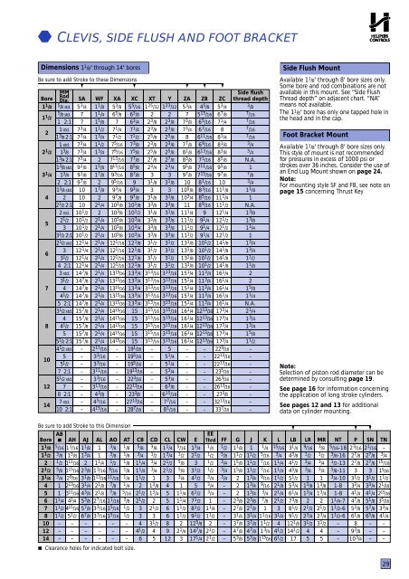
CLEVIS, SIDE FLUSH AND FOOT BRACKETDimensions 1 1 /8" through 14" boresBe sure to add Stroke to these Dimensions▼ ▼ ▼ ▼ ▼BoreMM<strong>Rod</strong>Dia. SA WF XA XC XT Y ZA ZB ZC1 1 /81 1 /222 1 /23 1 /4456781012145 /8 std.5 /8 std.1 2:11 s t d .1 3 /8 2 : 11 s t d .1 3 /81 3 /4 2 : 11 3 /8 std.1 3 /42 2:11 3 /4 std.22 1 /2 2 : 12 s t d .2 1 /233 1 /2 2 : 12 1 /2 std.33 1 /24 2 : 13 s t d .3 1 /244 1 /25 2 : 13 1 /2 std.44 1 /255 1 /2 2 : 14 1 /2 std.55 1 /27 2 : 15 1 /2 std.78 2 : 17 s t d .1 0 2 : 15 3 /4777 3 /47 3 /47 3 /47 3 /47 3 /49 1 /89 1 /89 7 /810101010 1 /210 1 /210 1 /210 1 /212 1 /412 1 /412 1 /412 1 /414 7 /814 7 /814 7 /814 7 /814 7 /815 7 /815 7 /815 7 /815 7 /815 7 /8–––––––––1 1 /81 1 /41 5 /81 1 /21 3 /41 1 /21 3 /421 5 /81 7 /821 7 /822 1 /422 1 /42 1 /42 1 /42 1 /42 1 /42 1 /42 1 /42 1 /42 1 /42 1 /42 1 /42 1 /42 1 /42 1 /42 1 /42 1 /42 1 /42 15 /163 3 /163 3 /163 11 /163 3 /163 13 /164 3 /84 5 /164 15 /165 3 /86 5 /877 1 /47 1 /27 5 /167 9 /167 13 /168 15 /169 3 /169 5 /169 3 /49 7 /81 0 1 /81 0 3 /81 0 5 /81 0 5 /81 0 5 /81 2 1 /161 2 1 /161 2 1 /161 2 1 /161 3 1 5 /1 61 3 1 5 /1 61 3 1 5 /1 61 3 1 5 /1 61 3 1 5 /1 61 4 1 5 /1 61 4 1 5 /1 61 4 1 5 /1 61 4 1 5 /1 61 4 1 5 /1 6–––––––––5 5 /166 3 /86 3 /47 1 /47 1 /27 3 /87 5 /87 7 /88 5 /88 7 /899 3 /49 7 /810 1 /810 1 /210 3 /410 3 /410 3 /412 1 /812 1 /812 1 /812 1 /813 3 /413 3 /413 3 /413 3 /413 3 /415151515151 9 1 /1 61 9 5 /1 61 9 5 /1 61 9 1 3 /1 62 2 3 /1 62 2 1 3 /1 62 3 3 /82 7 1 3 /1 62 8 7 /1 61 25 /3222 3 /82 3 /82 5 /82 3 /82 5 /82 7 /82 3 /433 1 /833 1 /83 3 /83 1 /83 3 /83 3 /83 3 /83 1 /23 1 /23 1 /23 1 /23 13 /163 13 /163 13 /163 13 /163 13 /163 15 /163 15 /163 15 /163 15 /163 15 /16–––––––––1 23 /3222 3 /82 3 /82 5 /82 3 /82 5 /82 7 /82 3 /433 1 /833 1 /83 3 /83 1 /83 3 /83 3 /83 3 /83 1 /23 1 /23 1 /23 1 /23 13 /163 13 /163 13 /163 13 /163 13 /163 15 /163 15 /163 15 /163 15 /163 15 /1655 1 /45 1 /45 3 /45 3 /46 3 /86 15 /167 7 /168 1 /165 3 /477 3 /87 3 /487 7 /88 1 /88 3 /89 5 /89 7 /81010 5 /810 3 /41111 1 /411 1 /211 1 /211 1 /213 1 /813 1 /813 1 /813 1 /815 1 /415 1 /415 1 /415 1 /415 1 /416 1 /416 1 /416 1 /416 1 /416 1 /4–––––––––4 5 /85 15 /166 5 /166 7 /166 11 /166 9 /166 13 /167 1 /167 11 /167 15 /168 1 /168 3 /168 5 /168 9 /1699 1 /49 1 /49 1 /410 1 /210 1 /210 1 /210 1 /211 3 /411 3 /411 3 /411 3 /411 3 /41 2 1 3 /1 61 2 1 3 /1 61 2 1 3 /1 61 2 1 3 /1 61 2 1 3 /1 6–––––––––5 3 /46 7 /87 1 /488 1 /48 1 /88 3 /88 5 /89 5 /89 7 /81011 1 /811 1 /411 1 /212 1 /412 1 /212 1 /212 1 /214 1 /814 1 /814 1 /814 1 /816 1 /416 1 /416 1 /416 1 /416 1 /417 3 /417 3 /417 3 /417 3 /417 3 /42 2 9 /1 62 2 1 3 /1 62 2 1 3 /1 62 3 5 /1 62 6 3 /1 62 6 1 3 /1 62 7 3 /83 2 1 3 /1 63 3 7 /1 6Side flushthread depth3 /87 /167 /167 /167 /163 /43 /4N.A.17 /83 /41 1 /81N.A.1 3 /81 3 /81 1 /411 3 /41 3 /41 1 /21 1 /8221 5 /81 1 /4N.A.2 1 /41 3 /41 3 /41 5 /81 1 /2–––––––––Side Flush MountAvailable 1 1 /8" through 8" bore sizes only.Some bore and rod combinations are notavailable in this mount. See “Side FlushThread depth” on adjacent chart. “NA”means not available.T h e 1 1 /8" bore has only one tapped hole inthe head and in the cap.Foot Bracket MountAvailable 1 1 /8" through 8" bore sizes only.This style of mount is not recommendedfor pressures in excess of 1000 psi orstrokes over 36 inches. Consider the use ofan End Lug Mount shown on page 24.Note:For mounting style SF and FB, see note onpage 15 concerning Thrust KeyNote:Selection of piston rod diameter can bedetermined by consulting page 19.See page 16 for information concerningthe application of long stroke <strong>cylinder</strong>s.See pages 12 and 13 for additionaldata on <strong>cylinder</strong> mounting.Be sure to add Stroke to this Dimension ▼ ▼ ▼ABEEBore ■ AH AJ AL AO AT CB CD CL CW E Thrd FF G J K L LB LR MR NT P SN TN1 1 /8 5 /16 1 1 /16 1 1 /8 1 3 /8 1 /8 5 /8 3 /8 1 1 /4 5 /16 1 3 /4 1 /4 1 /2 1 1 /8 1 1 /4 15 /16 3 1 /4 9 /16 3 /8 5 /16-18 2 3 /16 2 1 /16 –1 1 /2 3 /8 1 3 /8 1 3 /4 1 3 /8 1 /8 3 /4 1 /2 1 3 /4 1 /2 2 1 /2 1 /2 5 /8 1 1 /2 1 1 /2 5 /16 3 /4 4 3 /8 1 /2 1 /2 3 /8-16 2 7 /8 2 7 /8 3 /42 1 /2 1 11 /1 6 2 1 1 /4 1 /2 1 /8 1 1 /4 3 /4 2 1 /2 5 /8 3 1 /2 3 /4 1 5 /8 1 1 /2 7 /16 1 1 /4 4 1 /2 3 /4 3 /4 1 /2-13 2 7 /8 2 7 /8 15 /162 1 /2 5 /8 1 15 /1 6 2 3 /8 1 3 /16 9 /16 1 /8 1 1 /4 3 /4 2 1 /2 5 /8 3 1 /2 1 /2 3 /4 1 5 /8 1 1 /2 7 /16 1 1 /4 4 5 /8 3 /4 3 /4 5 /8-11 3 3 1 5 /1 63 1 /4 3 /4 2 9 /1 6 3 1 /8 1 13 /1 6 /16 1 /4 1 1 /2 1 3 3 /4 4 1 /2 3 /4 3 /4 2 1 3 /4 9 /16 1 1 /2 5 1 /2 1 1 3 /4-10 3 1 /2 3 1 /2 1 1 /24 1 2 13 /1 6 3 1 /4 2 1 /8 7 /8 1 /4 2 1 3 /8 4 1 5 3 /4 – 2 1 3 /4 9 /16 2 1 /8 5 3 /4 1 3 /8 1 3 /8 1-8 3 3 /4 3 3 /4 2 1 /1 65 1 3 11 /1 6 4 3 /4 2 1 /8 7 /8 5 /16 2 1 /2 1 3 /4 5 1 1 /4 6 1 /2 3 /4 – 2 1 3 /4 3 /4 2 1 /4 6 1 /4 1 3 /4 1 3 /4 1-8 4 1 /4 4 1 /4 2 15 /1 66 1 1 /4 4 1 /4 5 3 /8 2 7 /16 1 1 /16 3 /8 2 1 /2 2 5 1 1 /4 7 1 /2 1 – 2 3 /8 2 3 /8 7 /8 2 1 /2 7 3 /8 2 2 1 1 /4-7 4 7 /8 5 1 /8 3 5 /1 67 1 1 /2 4 15 /1 6 5 7 /8 3 3 /16 1 5 /16 1 /2 3 2 1 /2 6 1 1 /2 8 1 /2 1 1 /4 – 2 7 /8 2 7 /8 1 3 8 1 /2 2 1 /2 2 1 /2 1 1 /2-6 5 3 /8 5 7 /8 3 3 /48 1 1 /2 5 1 /2 6 7 /8 3 3 /16 1 5 /16 1 /2 3 3 6 1 1 /2 9 1 /2 1 1 /2 – 3 1 /4 3 1 /4 1 1 /16 3 1 /4 9 1 /2 2 3 /4 2 3 /4 1 1 /2-6 6 1 /8 6 5 /8 4 1 /410 – – – – – – 4 3 1 /2 8 2 12 5 /8 2 – 3 7 /8 3 7 /8 1 1 /2 4 12 1 /8 3 1 /2 3 1 /2 – 8 – –12 – – – – – – 4 1 /2 4 9 2 1 /4 14 7 /8 2 1 /2 – 4 7 /8 4 7 /8 1 3 /4 4 1 /2 14 1 /2 4 4 – 9 3 /8 – –14 – – – – – – 6 5 12 3 17 1 /4 2 1 /2 – 5 3 /8 5 3 /8 1 15 /1 6 6 1 /2 17 5 5 – 10 3 /4 – – Clearance holes for indicated bolt size.29