Hydraulic cylinder Tie Rod Design - imperial - Duncan Rogers
Hydraulic cylinder Tie Rod Design - imperial - Duncan Rogers
Hydraulic cylinder Tie Rod Design - imperial - Duncan Rogers

You also want an ePaper? Increase the reach of your titles
YUMPU automatically turns print PDFs into web optimized ePapers that Google loves.
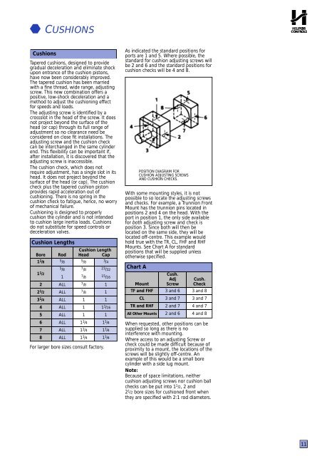
CUSHIONSCushionsTapered cushions, designed to providegradual deceleration and eliminate shockupon entrance of the cushion pistons,have now been considerably improved.The tapered cushion has been marriedwith a fine thread, wide range, adjustingscrew. This new combination offers apositive, low-shock deceleration and amethod to adjust the cushioning effectfor speeds and loads.The adjusting screw is identified by acrossslot in the head of the screw. It doesnot project beyond the surface of thehead (or cap) through its full range ofadjustment so no clearance need beconsidered on close fit installations. Theadjusting screw and the cushion checkcan be interchanged in the same <strong>cylinder</strong>end. This flexibility can be important if,after installation, it is discovered that theadjusting screw is inaccessible.The cushion check, which does notrequire adjustment, has a single slot in itshead. It does not project beyond thesurface of the head (or cap). The cushioncheck plus the tapered cushion pistonprovides rapid acceleration out ofcushioning. There is no spring in thecushion check to fatigue, hence, no worryof mechanical failure.Cushioning is designed to properlycushion the <strong>cylinder</strong> and is not intendedto cushion large inertia loads. Cushionsdo not substitute for speed controls ordeceleration valves.Cushion LengthsCushion LengthBore <strong>Rod</strong> Head Cap1 1 /81 1 /222 1 /23 1 /4456785 /85 /81ALLALLALLALLALLALLALLALL5 /87 /87 /87 /87 /81111 1 /41 1 /41 1 /4For larger bore sizes consult factory.3 /423 /3215 /161111 1 /1611 1 /41 1 /41 1 /4As indicated the standard positions forports are 1 and 5. Where possible, thestandard for cushion adjusting screws willbe 2 and 6 and the standard positions forcushion checks will be 4 and 8.POSITION DIAGRAM FORCUSHION ADJUSTING SCREWSAND CUSHION CHECKS.With some mounting styles, it is notpossible to so locate the adjusting screwsand checks. For example, a Trunnion FrontMount has the trunnion pins located inpositions 2 and 4 on the head. With theport in position 1, the only side availablefor both adjusting screw and check isposition 3. Since both will then belocated on the same side, they will belocated off-centre. This example wouldhold true with the TR, CL, FHF and RHFMounts. See Chart A for standardpositions that will be supplied unlessotherwise specified.Chart AMountTF and FHFCLTR and RHFAll Other MountsCush.AdjScrew3 and 63 and 72 and 72 and 6Cush.Check3 and 83 and 74 and 74 and 8When requested, other positions can besupplied so long as there is nointerference with mounting.Where access to an adjusting Screw orcheck could be made difficult because ofproximity to a mount, the locations of thescrews will be slightly off-centre. Anexample of this would be a small bore<strong>cylinder</strong> with a side lug mount.Note:Because of space limitations, neithercushion adjusting screws nor cushion ballchecks can be put into 1 1 /2, 2 and2 1 /2 bore sizes for cushioned front whenthey are specified with 2:1 rod diameters.11