INSTALLATION AND MAINTENANCEStorageIf it is necessary to store a <strong>cylinder</strong> for aperiod of time prior to installation, thefollowing procedures should be adhered to:1 . Do not store out of doors or in a highhumidity or corrosive atmospherewithout a positive method of internaland external corrosion protection.2 . Where any adverse storage conditionsexist, coat all unpainted external parts,including the piston rod, withcorrosion inhibitive material. Fill bothends of the <strong>cylinder</strong> with a corrosionpreventative fluid compatible with thesystem flu i d .3 . If possible, store the <strong>cylinder</strong> in avertical position, piston rod up.4 . Dirt protector plugs should be kept inthe ports during storage.InstallationDetails on each specific mount are givenin our HH Series Catalogue and referenceshould be made to the section on“Mountings”. In addition, the followinggeneral procedures should be followed:1 . On all rigidly mounted <strong>cylinder</strong>s, besure that the part which attaches tothe piston rod exactly “lines up” withthe piston rod travel, or make provisionfor axial misalignment.2 . Flange mounted <strong>cylinder</strong>s should besolidly mounted to a rigid section ofthe machine with high tensile bolts(socket head type recommended).When a pilot diameter cannot be usedfor alignment, the <strong>cylinder</strong> must bealigned to the work, tightened inplace, and the flange drilled for adowel and pinned to prevent shifting.For horizontal installations of fla n g emount <strong>cylinder</strong>s with 48" of stroke andl o n g e r, we recommend supportingboth ends of the <strong>cylinder</strong>.3. Side mounted <strong>cylinder</strong>s (Styles SL, CL,EL, FB and SF) used under shockconditions or at high pressure ranges(over 1500 psi) should be doweled orkeyed to the machine. Styles SL, CLand EL have room for dowel pins inthe mounting lugs. On Style FBmounts, two pins and one bolt can beused on one end to take the thrust.Cylinders should be pinned or keyed atone end only (especially important onlong stroke <strong>cylinder</strong>s) due to thed e flection that takes place under load.On long stroke applications, theaddition of an intermediate support(between the <strong>cylinder</strong> heads to supportthe tube and tie rods) is very importantand is recommended. Care should beexercised in fastening the intermediatesupport so that no "humping" of the<strong>cylinder</strong> occurs. An intermediatesupport is utilised to afford additional<strong>cylinder</strong> support and is not designed toabsorb thrust.4. All clevis and trunnion mount <strong>cylinder</strong>sneed provisions on both ends forpivoting in one direction. Alignment inthe other direction is essential to avoidexcessive side loading. Wherealignment in one direction is notpossible, the <strong>cylinder</strong> must be equippedwith two-direction pivoting such as canbe obtained with a spherical bearing.See HH Series catalogue for a completeline of mounting accessories.5. On trunnion mount <strong>cylinder</strong>s, usepillow blocks of ample size, rigidlymounted as close to the <strong>cylinder</strong>heads as possible. Bearing should beprovided for the full length of thetrunnion pins. Lubrication should beprovided to the pins.PipingBSP ports will be fitted as standard unlessotherwise requested. Ports in the HHseries can be supplied as requested withN.P.T. (American standard taper pipethread). These threads are designed to beused with a sealing compound. Sealingcompounds should be used sparingly.Teflon tape forms an excellent pipe threadsealer. No compound or tape should beused on the first 1 1 /2 threads. This willprevent sealing compound or tape fromentering the system. Tapered pipe threadsshould be tightened only enough toprevent leakage. Over tightening canresult in permanently distorted threadsthat will never give leak-proof seal.BleedingIf a <strong>cylinder</strong> is equipped with optional airbleeds, after the <strong>cylinder</strong> has been fullyconnected and the system has been filledwith fluid, cycle the <strong>cylinder</strong> and bleedthe air by loosening the air bleed plugsalternately. Loosen just enough to releasethe air bubbles. Tighten when no moreair escapes. See note on Page 14.MaintenancePlease note when doing maintenancework on HH series <strong>cylinder</strong>s:1. The tie rod nuts need not be loosenedor removed to service the rod bearingor gland except on mounting styles,BX, C, FF, FFX, RF, RFX, RHF and T on1 1 /8" through 2 1 /2" bores, and 3 1 /4"bore with 2" diameter rod.2. One piece piston constructioneliminates the need for removing thepiston from the piston rod.3. All parts removed from the <strong>cylinder</strong>that are to be re-used should bethoroughly cleaned. Be sure tocarefully clean all cavities and groovesprior to replacing parts. All parts, newand old, should be lightly lubricatedwith a clean lubricant of the same typeas, or compatible with, the fluid beingused in the <strong>cylinder</strong>.4. When a <strong>cylinder</strong> is disassembled, it is agood practice to replace all static andmoving seals.TO REPLACE ROD BEARING, RODPACKING, ROD WIPER, OR ROD GLANDSEAL extend the piston rod (item 3) 1 /4 o fthe stroke. CAUTION! Support the rod endat all times to prevent nicking and to avoidcocking the piston in the tube. Inspect thepiston rod wrench flats for burrs. Removeany burrs to prevent damage to the rodpacking, rod wiper, or bearing when it isslipped off the rod. Remove rod packinggland retainer screws (item 10) and therod gland retainer (item 6) or the rodgland (item 6A) on the single piececonstruction. On front flange and frontflange extra mounts, 1 1 /8" through 2 1 /2"bores and 3 1 /4" bore with 2" rod, the tierod nuts (item 13) on the rear face of thecap must be removed as the tie rods arethreaded into the flange. On rear flange,rear extra flange, clevis, and intermediatetrunnion mounts, 1 1 /8" through 2 1 /2" boresand 3 1 /4" bore with 2" rod, the tie rodnuts on the face of the gland retainermust be removed. After the gland orgland retainer has been removed, the rodpacking may be removed from the gland.Place the rod gland on a clean, flat surfacewith the rod packing end up. Use a smallscrewdriver to remove the rod packing set(item 25) being careful not to nick orscratch the bore of the packing cavity.Remove the rod wiper in the samem a n n e r, being careful not to nick orscratch the wiper cavity. When replacingthe rod wiper be sure it is fully seated inthe groove. When replacing the rodpacking, apply a light coating of cleanlubricant to the new seal and insert it intothe gland firmly with the fin g e r s .To remove the rod bearing (item 21), firstremove the rod gland seal (item 22). Thiswill expose the chamfer on the outsideedge of the bearing against the head.Place two small pry bars or screwdriversinto the chamfer and pry the bearinggently out of the <strong>cylinder</strong>. Be sure tosupport the end of the rod. Inspect thebearing and rod for scoring, galling, etc.Replace any damaged parts. Replace thebearing by pushing or lightly tappingwith a plastic hammer until its seated intothe head. Lubricate the gland seal andplace around the bearing. Slide the rodpacking gland onto the rod taking carethat the rod packing set is not damagedwhen being passed over the rod endthreads and wrench flats. Be careful thatthe gland seal is not pinched or cut as thepacking gland is brought up against thehead. Replace the gland retainer screws.See chart on page 34 for correct torquevalue for retainer screws. If the tie rodnuts have been removed, tighten themusing the values shown on the tie rodtorque chart. If the piston packings ortube seals are to be serviced, do notreplace the rod gland or bearing until thisservice has been completed.TO REPLACE TUBE SEALS, PISTON SEAL,AND PISTON BEARING STRIP. Remove thetie rod nuts (item 13) and remove the tierods (item 5) CAUTION! Support thepiston rod and piston assembly at alltimes. Remove the cap (item 2) and thetube (item 4). Examine the tube seals(item 16) for nicks, cuts, or grooves, andreplace if necessary. The new seals shouldbe lubricated before inserting into thegrooves. (NOTE: When a <strong>cylinder</strong> hasbeen disassembled to this degree, it isalways wise to replace all seals andbearings.)32
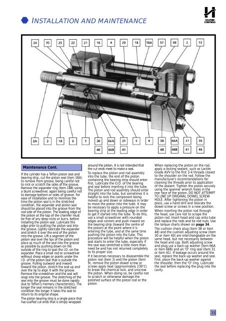
INSTALLATION AND MAINTENANCEMaintenance Cont.If the <strong>cylinder</strong> has a Te flon piston seal andbearing strip, cut the piston seal (item 18A)to remove from groove, being careful notto nick or scratch the sides of the groove.Remove the expander ring (item 18B) usinga blunt screwdriver, again being careful notto damage bottom or sides of groove. Fo rease of installation and to minimise thetime the piston seal is in the stretchedcondition, the expander and piston sealshould be placed into the groove from therod side of the piston. The leading edge ofthe piston at the top of the chamfer mustbe free of any deep nicks or burrs, beforeinstalling the piston seal. Lubricate thisedge prior to putting the piston seal intothe groove. Lightly lubricate the expanderand stretch it over the end of the pistoninto the groove. Lift a segment of thepiston seal over the lips of the piston andplace as much of the seal into the grooveas possible by pushing down on theoutside of the ring to seat the l.D. on thee x p a n d e r. Place a small rod or screwdriverwithout sharp edges or points under thel.D. of the piston seal that is outside thegroove. Pulling outward and inwardtoward the piston, stretch the seal up andover the lip to align it with the groove.Remove the screwdriver and the seal willsnap into the groove. The stretching of theseal into the groove must be done rapidlydue to Te flon’s memory characteristics. Thelonger the seal remains in the stretchedcondition the longer it takes the seal toreturn to its original s h a p e .The piston bearing strip is a single piece thathas scarfed cut ends that is simply wrappedaround the piston. It is not intended thatthe cut ends meet to make a seal.To replace the piston and rod assemblyinto the tube, the end of the pistoncontaining the bearing strip should enterfirst. Lubricate the O.D. of the bearingand seal before inserting it into the tube.The piston and rod assembly should enterstraight into the tube, but sometimes it ishelpful to rock the component beingmoved up and down or sideways in orderto move the piston into the tube. It maybe necessary to apply a pressure on thebearing strip at the leading edge in orderto get it started into the tube. To do this,use a small screwdriver with roundededges and corners and push inward onthe bearing strip (toward the centre ofthe piston) at the point where it isentering the tube, and at the same timepushing the piston into the tube. Thisprocedure will be helpful when the pistonseal starts to enter the tube, especially ifthe seal was stretched a little more thanneed be and has not returned completelyto its proper size.If it becomes necessary to disassemble thepiston rod (item 3) and the piston (item9), remove the piston dowel screw orscrews apply heat (approximately 230°C)to break the chemical lock, and unscrewthe piston. When doing so, be careful notto scratch or otherwise damage thepolished surface of the piston rod or thepiston.When replacing the piston on the rod,apply a locking sealant, such as LoctiteGrade AVV to the first 3-4 threads closestto the shoulder on the rod. Follow themanufacturer's recommendations forcleaning the threads prior to applicationof the sealant. Tighten the piston securelyusing the spanner wrench holes in therear face of the piston. DO NOT ATTEMPTTO LINE UP ORIGINAL DOWEL SCREWHOLE. After tightening the piston inplace, use a hand drill and relocate thedowel screw or screws in a new position.When inserting the piston rod throughthe head, use care not to scrape thepiston rod. Insert head and cap onto tubeand replace the rods and tie rod nuts. Usethe torque charts shown on page 34.The cushion check plug (item 38 or item48) and the cushion adjusting screw (item30 or item 40) are interchangeable on thesame head, but not necessarily betweenthe head and cap. Both adjusting screwand plug use a back-up washer (item 66Aor item 66B) and an "O" ring seal (item 31or item 41). If leakage occurs around theseal, replace the back-up washer and seal.First, place the back-up washer againstthe shoulder, then the "O" ring. Lubricatethe seal before replacing the plug into thecavity.33