Hydraulic cylinder Tie Rod Design - imperial - Duncan Rogers
Hydraulic cylinder Tie Rod Design - imperial - Duncan Rogers
Hydraulic cylinder Tie Rod Design - imperial - Duncan Rogers

You also want an ePaper? Increase the reach of your titles
YUMPU automatically turns print PDFs into web optimized ePapers that Google loves.
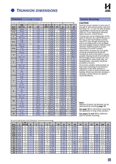
TRUNNION DIMENSIONSDimensions 1 1 /8" through 14" boresBe sure to add Stroke to these Dimensions ▼ ▼ ▼MMXI XIBore <strong>Rod</strong> Dia. W WF MIN MAX XG XJ Y ZB1 1 /8 5 /8 std. 5 /8 1 1 /8 2 3 /4 2 7 /8 1 23 /32 3 29 /32 1 23 /32 4 5 /81 1 /25 /8 std. /8 1 1 /4 3 3 /8 3 1 /2 2 4 7 /8 2 5 15 /161 2:1 1 1 5 /8 3 3 /4 3 7 /8 2 3 /8 5 1 /4 2 3 /8 6 5 /1621 std. /4 1 1 /2 3 7 /8 3 3 /4 2 3 /8 5 1 /4 2 3 /8 6 7 /161 3 /8 2:1 1 1 3 /4 4 1 /8 4 2 5 /8 5 1 /2 2 5 /8 6 11 /161 std. 3 /4 1 1 /2 3 7 /8 3 7 /8 2 3 /8 5 3 /8 2 3 /8 6 9 /162 1 /2 1 3 /8 1 1 3 /4 4 1 /8 4 1 /8 2 5 /8 5 5 /8 2 5 /8 6 13 /161 3 /4 2:1 1 1 /4 2 4 3 /8 4 3 /8 2 7 /8 5 7 /8 2 7 /8 7 1 /161 3 /8 std. – 1 5 /8 4 5 /8 4 3 /8 2 3 /4 6 1 /4 2 3 /4 7 11 /163 1 /4 1 3 /4 – 1 7 /8 4 7 /8 4 5 /8 3 6 1 /2 3 7 15 /162 2:1 – 2 5 4 3 /4 3 1 /8 6 5 /8 3 1 /8 8 1 /161 3 /4 std. – 1 7 /8 5 4 3 /4 3 6 3 /4 3 8 3 /164 2 – 2 5 1 /8 4 7 /8 3 1 /8 6 7 /8 3 1 /8 8 5 /162 1 /2 2:1 – 2 1 /4 5 3 /8 5 1 /8 3 3 /8 7 1 /8 3 3 /8 8 9 /162 std. – 2 5 1 /8 5 3 /8 3 1 /8 7 3 /8 3 1 /8 952 1 /2 – 2 1 /4 5 3 /8 5 5 /8 3 3 /8 7 5 /8 3 3 /8 9 1 /43 – 2 1 /4 5 3 /8 5 5 /8 3 3 /8 7 5 /8 3 3 /8 9 1 /43 1 /2 2:1 – 2 1 /4 5 3 /8 5 5 /8 3 3 /8 7 5 /8 3 3 /8 9 1 /42 1 /2 std. – 2 1 /4 6 1 /8 5 3 /4 3 1 /2 8 3 /8 3 1 /2 10 1 /263 – 2 1 /4 6 1 /8 5 3 /4 3 1 /2 8 3 /8 3 1 /2 10 1 /23 1 /2 - 2 1 /4 6 1 /8 5 3 /4 3 1 /2 8 3 /8 3 1 /2 10 1 /24 2:1 – 2 1 /4 6 1 /8 5 3 /4 3 1 /2 8 3 /8 3 1 /2 10 1 /23 std. – 2 1 /4 6 5 /8 6 3 /8 3 5 /8 9 3 /8 3 13 /16 11 3 /43 1 /2 – 2 1 /4 6 5 /8 6 3 /8 3 5 /8 9 3 /8 3 13 /16 11 3 /47 4 – 2 1 /4 6 5 /8 6 3 /8 3 5 /8 9 3 /8 3 13 /16 11 3 /44 1 /2 – 2 1 /4 6 5 /8 6 3 /8 3 5 /8 9 3 /8 3 13 /16 11 3 /45 2:1 – 2 1 /4 6 5 /8 6 3 /8 3 5 /8 9 3 /8 3 13 /16 11 3 /43 1 /2 std. – 2 1 /4 7 1 /4 6 3 /4 3 3 /4 10 1 /4 3 15 /16 12 13 /164 – 2 1 /4 7 1 /4 6 3 /4 3 3 /4 10 1 /4 3 15 /16 12 13 /168 4 1 /2 – 2 1 /4 7 1 /4 6 3 /4 3 3 /4 10 1 /4 3 15 /16 12 13 /165 – 2 1 /4 7 1 /4 6 3 /4 3 3 /4 10 1 /4 3 15 /16 12 13 /165 1 /2 2:1 – 2 1 /4 7 1 /4 6 3 /4 3 3 /4 10 1 /4 3 15 /16 12 13 /164 1 /2 std. – 2 15 /16 9 1 /16 8 15 /16 4 3 /4 13 1 /4 5 16 9 /16105 – 3 3 /16 9 5 /16 9 3 /16 5 13 1 /2 5 1 /4 16 13 /165 1 /2 – 3 3 /16 9 5 /16 9 3 /16 5 13 1 /2 5 1 /4 16 13 /167 2:1 – 3 11 /16 9 13 /16 9 11 /16 5 1 /2 14 5 3 /4 17 5 /165 1 /2 std. – 3 3 /16 10 13 /16 10 1 /16 5 3 /8 15 1 /2 5 3 /4 19 7 /1612 7 – 3 13 /16 11 7 /16 10 11 /16 6 16 1 /8 6 3 /8 20 1 /168 2:1 – 4 3 /8 12 11 1 /4 6 9 /16 16 11 /16 6 15 /16 20 5 /8147 std. – 4 5 /16 12 11 /16 12 15 /16 6 27 /32 18 25 /32 7 7 /16 23 1 /410 2:1 – 4 15 /16 13 5 /16 13 9 /16 7 15 /32 19 13 /32 8 1 /16 23 7 /8Trunnion MountingsCAUTIONTrunnion mount <strong>cylinder</strong>s in bore sizes 5"through 8" with oversize piston rods andbore sizes 10", 12" and 14" with all pistonrod diameters should not be used over2000 psi. If your application demandshigher pressure, consult factory.Trunnion pins are an integral part of thehead (TF Mount), the cap (TR Mount), orthe ring on the intermediate trunnionmount (T). Even though machining thepins as an integral part is the strongest,and most fatigue-resistant method, someattention should be given to propermounting of trunnion <strong>cylinder</strong>s.Pillow blocks of ample size and rigidityshould be provided and should bemounted as close to the head or cap aspossible. Bearing should be provided forthe full length of the trunnion pin. Pinsare designed for shear loads only, notbending loads. Lubrication should beprovided to the pins.All trunnion <strong>cylinder</strong>s need provision onboth ends of pivoting in one direction.Alignment in the other direction isessential in order to avoid excessive sideloading. Where two-direction pivoting isnecessary, contact factory for specificrecommendations.Note:Selection of piston rod diameter can bedetermined by consulting page 19.See page 16 for information concerningthe application of long stroke <strong>cylinder</strong>s.See pages 12 and 13 for additionaldata on <strong>cylinder</strong> mounting.Be sure to add Stroke to this Dimension▼EEBore E Thread FF G J K P TB TD TL TM TR TT TU TW UM UT1 1 /8 1 3 /4 1 /4 1 /2 1 1 /8 1 1 /4 2 3 /16 2 3 /4 3 /4 3 /4 1 3 /413 1 /4 3 1 /41 1 /2 2 1 /2 1 /2 5 /8 1 1 /2 1 1 /2 5 /16 2 7 /8 3 1 /2 1 1 31 1 /45 4 1 /22 3 1 /2 3 /4 1 5 /8 1 1 /2 7 /16 2 7 /8 4 1 3 /8 1 3 /8 3 1 /2 1 1 /26 1 /4 5 3 /42 1 /2 3 1 /2 1 /2 3 /4 1 5 /8 1 1 /2 7 /16 3 5 1 3 /8 1 3 /8 41 1 /26 3 /4 6 1 /43 1 /4 4 1 /2 3 /4 3 /4 2 1 3 /4 9 /16 3 1 /2 – 1 3 /4 1 3 /4 5 7 2 1 2 1 /2 8 1 /2 84 5 3 /4 – 2 1 3 /4 9 /16 3 3 /4 – 1 3 /4 1 3 /4 6 7 1 /4 2 1 /4 1 2 1 /2 9 1 /2 8 1 /25 6 1 /2 3 /4 – 2 1 3 /4 3 /4 4 1 /4 – 1 3 /4 1 3 /4 7 8 3 /4 2 1 /4 1 2 1 /2 10 1 /2 106 7 1 /2 1 – 2 3 /8 2 3 /8 7 /8 4 7 /8 – 2 2 8 1 /2 10 1 /4 3 1 2 1 /2 12 1 /2 11 1 /27 8 1 /2 1 1 /4 – 2 7 /8 2 7 /8 1 5 3 /8 – 2 1 /2 2 1 /2 9 3 /4 12 3 1 1 /4 3 14 3 /4 13 1 /28 9 1 /2 1 1 /2 – 3 1 /4 3 1 /4 1 1 /16 6 1 /8 – 3 3 11 13 3 1 /2 1 1 /4 3 1 /2 17 15 1 /210 12 5 /8 2 – 3 7 /8 3 7 /8 1 1 /2 8 – 3 1 /2 3 1 /2 14 16 1 /2 4 1 /2 1 3 /8 4 21 19 5 /812 14 7 /8 2 1 /2 – 4 7 /8 4 7 /8 1 3 /4 9 3 /8 – 4 4 16 1 /2 19 1 /4 5 1 /2 1 1 /2 5 24 1 /2 22 7 /814 17 1 /4 2 1 /2 – 5 3 /8 5 3 /8 1 15 /16 10 3 /4 – 5 5 19 5 /8 22 1 /2 6 1 1 /2 5 29 5 /8 27 1 /427