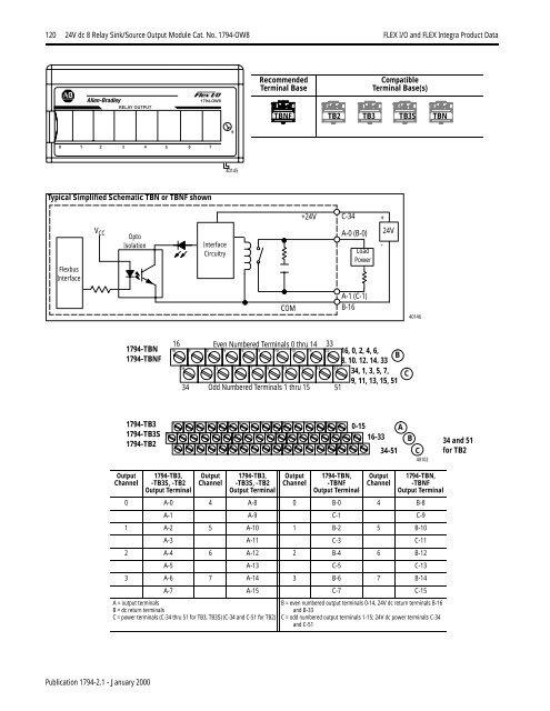
120 24V dc 8 Relay Sink/Source Output Module Cat. No. 1794-OW8 <strong>FLEX</strong> I/O <strong>and</strong> <strong>FLEX</strong> <strong>Integra</strong> Product Data24V dc 8 Relay Sink/Source Output Module Cat. No. 1794-OW8RecommendedTerminal BaseCompatibleTerminal Base(s)RELAY OUTPUT1794-OW8TBNF TB2 TB3 TB3S TBN90 1 2 3 4 5 6 740145Typical Simplified Schematic TBN or TBNF shownFlexbusInterfaceV CCOptoIsolationInterfaceCircuitry+24VC-34A-0 (B-0)LoadPower+-24VCOMA-1 (C-1)B-16401461794-TBN1794-TBNF16 Even Numbered Terminals 0 thru 14 3316 0 2 4 6 8 10 12 14 33 16, 0, 2, 4, 6,B8. 10. 12. 14. 3334 1 3 5 7 9 11 13 15 5134, 1, 3, 5, 7,9, 11, 13, 15, 5134 Odd Numbered Terminals 1 thru 15 51C1794-TB31794-TB3S1794-TB20 1 2 3 4 5 6 7 8 9 10 11 12 13 14 1516 17 18 19 20 21 22 23 24 25 26 27 28 29 30 31 32 3334 35 36 37 38 39 40 41 42 43 44 45 46 47 48 49 50 510-15 A16-3334-51BC4010234 <strong>and</strong> 51for TB2OutputChannel1794-TB3,-TB3S, -TB2Output TerminalOutputChannel1794-TB3,-TB3S, -TB2Output TerminalOutputChannel1794-TBN,-TBNFOutput TerminalOutputChannel1794-TBN,-TBNFOutput Terminal0 A-0 4 A-8 0 B-0 4 B-8A-1 A-9 C-1 C-91 A-2 5 A-10 1 B-2 5 B-10A-3 A-11 C-3 C-112 A-4 6 A-12 2 B-4 6 B-12A-5 A-13 C-5 C-133 A-6 7 A-14 3 B-6 7 B-14A-7 A-15 C-7 C-15A = output terminalsB = dc return terminalsC = power terminals (C-34 thru 51 for TB3, TB3S) (C-34 <strong>and</strong> C-51 for TB2)B = even numbered output terminals 0-14, 24V dc return terminals B-16<strong>and</strong> B-33C = odd numbered output terminals 1-15; 24V dc power terminals C-34<strong>and</strong> C-51Publication 1794-2.1 - January 2000
<strong>FLEX</strong> I/O <strong>and</strong> <strong>FLEX</strong> <strong>Integra</strong> Product Data 24V dc 8 Relay Sink/Source Output Module Cat. No. 1794-OW8 121ATTENTION!Do not attempt to increase load current or wattagecapability beyond the maximum rating byconnecting 2 or more outputs in parallel. Theslightest variation in relay switching time may causeone relay to momentarily switch the total loadcurrent.Apply only +24V dc power to the power terminalson the terminal base unit. Make certain that all relaywiring is properly connected before applying anypower to the module.Total current draw through the terminal base unit islimited to 10A. Separate power connections to theterminal base unit may be necessary.Simplified Schematic of Relay Module+24Vdc120VacLoad power can be obtained from a variety of sources, <strong>and</strong> can rangefrom +5V dc to 240V ac. Make certain that only 24V dc is applied tothe module power terminals on the module terminal baseSpecifications - 1794-OW8Outputs per ModuleModule LocationOff-State LeakageCurrent (max at 240V ac)Output Voltage Range (loaddependent)Output Current Rating(at rated power)Power Rating(steady state)24Vdc48Vdc240Vac24Vdc120Vac8 Form A isolated (normally open)electromechanical relaysCat. No. 1794-TBNF, -TB3, -TB3S, -TB2 or -TBNTerminal Base Unit1mA thru snubber circuit5-30V dc @ 2.0A resistive48V dc @ 0.5A resistive125V dc @ 0.25A resistive125V ac @ 2.0A resistive240V ac @ 2.0A resistive240VacRepresentative Examples of Various Relay LoadsRelay Load Contact Wiring125VdcResistive2A @ 5-30V dc0.5A @ 48V dc0.25A @ 125V dc2A @ 125V ac2A @ 240V acInductive2.0A steady state @ 5-30V dc, L/R = 7ms0.5A steady state @ 48V dc, L/R = 7ms0.25A steady state @ 125V dc, L/R = 7ms2.0A steady state, 15A make @ 125V ac,PF = cos θ = 0.42.0A steady state, 15A make @ 240V ac,PF = cos θ = 0.4250W max. for 125V ac resistive output480W max. for 240V ac resistive output60W max. for 30V dc resistive output24W max. for 48V dc resistive output31W max. for 125V dc resistive output250VA max. for 125V ac inductive output480VA max. for 240V ac inductive output60VA max. for 30V dc inductive output24VA max. for 48V dc inductive output31VA max. for 125V dc inductive outputdcReturn40155Isolation VoltageBetween any 2 setsof contactsCustomer load to logicCustomer load to 24Vdc supplyCustomer 24V dc supplyto logicOutput Signal DelayOFF to ONON to OFF2550V dc for 1s2550V dc for 1s2550V dc for 1s850V dc for 1sFlexbus Current (max)Power Dissipation Maximum 5.5WThermal Dissipation Maximum 18.8 BTU/hr8ms maximum (time from valid output on signal torelay energization by module)26ms maximum (time from valid output offsignal to relay deenergization by module)69mA @ 5V dcIndicators (field side 8 yellow status indicatorsindication, logic driven)Keyswitch position 9Initial Contact Resistance 30mΩSwitching Frequency 1 operation/3s (0.3Hz at rated load) maxOperate/Release Time Maximum 10msBounce Time1.2ms (mean)Minimum Contact Load 100µA at 100mV dcExpected Life ofMinimum 100,000 operations @ rated loadsElectrical ContactsFusing 1 Use a 1794-TBNF with a 3.0A Littelfuse 239003Max Inrush Current 15AGeneral SpecificationsExternal dc PowerSupply VoltageVoltage RangeSupply CurrentDimensions HxWxDEnvironmental ConditionsOperational TemperatureStorage TemperatureRelative HumidityShockOperatingNon-operatingVibrationConductors Wire SizeCategory24V dc nominal19.2 to 31.2V dc (includes 5% ac ripple)125mA maximum46mm x 94mm x 53mm (1.8in x 3.7in x 2.1in)0 to 55 o C (32 to 131 o F)-40 to 85 o C (-40 to 185 o F)5 to 95% noncondensing12g peak acceleration, 11(±1)ms pulse width50g peak acceleration, 11(±1)ms pulse widthTested 2g @ 10-500Hz per IEC 68-2-612 gauge (4mm 2 ) str<strong>and</strong>ed maximum3/64 inch (1.2mm) insulation maximum1 2PublicationInstallation Instructions 1794-5.19Agency Certification Meets URLR150 <strong>and</strong> C300;Meets IEC 1131 AC-15 Utilization CategoryClass I Division 2 certifiedGroups A, B, C, D certifiedClass I Zone 2 Group IIC certified1 Module outputs are not fused. If external fusing is desired, you must provide externalfusing.2 Use this conductor category information for planning conductor routing. Refer topublication 1770-4.1, “Industrial Automation Wiring <strong>and</strong> Grounding Guidelines for NoiseImmunity.”Publication 1794-2.1 - January 2000