


You also want an ePaper? Increase the reach of your titles
YUMPU automatically turns print PDFs into web optimized ePapers that Google loves.
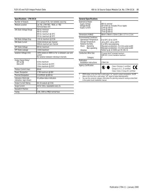
<strong>FLEX</strong> I/O <strong>and</strong> <strong>FLEX</strong> <strong>Integra</strong> Product Data 48V dc 16 Source Output Module Cat. No. 1794-OC16 89Specifications - 1794-OC16Number of Outputs 16 (1 group of 16), non-isolated, sourcingModule LocationCat. No. 1794-TB3, -TB3S, or -TB2Terminal Base UnitON-State Voltage Range 30V dc minimum48V dc nominal;60V dc maximum @ 45 o C55V dc maximum @ 55 o CON-State Voltage Drop 1.0V dc maximum @ 0.5AON-State Current2.0mA minimum per channel500mA maximum per channelOFF-State Voltage60V dc maximumOFF-State Leakage1.0mA maximumIsolation Voltage (min) 100% tested at 1900V dc for 1s between user <strong>and</strong>systemNo isolation between individual channelsOutput Signal Delay 1OFF to ONON to OFF0.5ms maximum1.0ms maximum @ 25 o C2.0ms maximum @ 55 o C80mA3.7W maximum @ 60V12.6 BTU/hr @ 60V dcFlexbus Current (max)Power DissipationThermal DissipationIndicators (field side 16 yellow status indicatorsindication, logic driven)Output Current Rating 8A (16 outputs @ 0.5A)Surge Current4A for 10ms, repeatable every 2sKeyswitch Position 2Fusing2.0A, 150V ac MQ2 normal fuseGeneral SpecificationsExternal dc PowerSupply VoltageVoltage RangeSupply CurrentDimensions HxWxDEnvironmental ConditionsOperational TemperatureStorage TemperatureRelative HumidityShock OperatingNon-operatingVibrationConductors Wire SizeCategoryPublicationInstallation Instructions 1794-5.54Agency Certification48V dc nominal30 to 60V dc (includes 5% ac ripple)13mA @ 30V dc21mA @ 48V dc27mA @ 60V dc46mm x 94mm x 53mm (1.8in x 3.7 in x 2.1in)0 to 55 o C (32 to 131 o F)-40 to 85 o C (-40 to 185 o F)5 to 95% noncondensing30g peak acceleration, 11(±1)ms pulse width50g peak acceleration, 11(±1)ms pulse widthTested 5g @ 10-500Hz per IEC 68-2-612 gauge (4mm 2 ) str<strong>and</strong>ed maximum3/64 inch (1.2mm) insulation maximum2 1Class I Division 2 certifiedGroups A, B, C, D certifiedClass I Zone 2 Group IIC certified1 Off/On delay is the time from a valid output “on” signal to output energization. On/Offdelay is the time from a valid output “off” signal to output deenergization.2 You use this conductor category information for planning conductor routing as describedin the system level installation manual.Publication 1794-2.1 - January 2000


