


You also want an ePaper? Increase the reach of your titles
YUMPU automatically turns print PDFs into web optimized ePapers that Google loves.
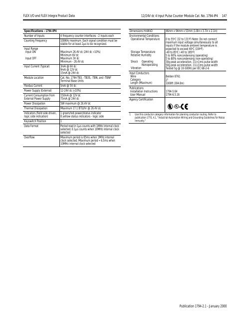
<strong>FLEX</strong> I/O <strong>and</strong> <strong>FLEX</strong> <strong>Integra</strong> Product Data 12/24V dc 4 Input Pulse Counter Module Cat. No. 1794-IP4 147Specifications - 1794-IP4Number of InputsCounting FrequencyInput RangeInput ONInput OFFInput Current (Typical)Module LocationFlexbus CurrentPower Supply (External) 12-24V dc (+10%)Current Consumption fromExternal Power SupplyPower DissipationThermal DissipationIndicators (field side driven,logic side indication)4 frequency counter interfaces - 2 inputs each100KHz maximum. Each signal condition must bestable for at least 2µs to be recognized.Maximum 26.4V dc (24V dc +10%)Minimum 6V dcMaximum 3V dcMinimum - 26.4V dc3mA @ 6V dc9mA @ 12V dc15mA @ 24V dcCat. No. 1794-TB3, -TB3S, -TBN, <strong>and</strong> -TBNFTerminal Base Units5mA @ 5V dc150mA @ 12V dc75mA @ 24V dc5W maximum @ 26.4V dcMaximum 17.1 BTU/hr @ 26.4V dc1 green/red power/status indicator8 yellow status indicators - logic sideKeyswitch Position 1Data FormatPeriod read in 1µs counts with 1MHz internal clockselected; 0.1µs counts when 10MHz internal clockselectedOverflowMaximum period is 65ms when 1MHz internalclock selected; Maximum period = 6.5ms when10MHz internal clock selectedDimensions HxWxDEnvironmental ConditionsOperational TemperatureStorage TemperatureRelative HumidityShock OperatingNonoperatingVibrationInput ConductorsWireCategoryLength (Maximum)PublicationsInstallation InstructionsUser ManualAgency Certification46mm x 94mm x 53mm (1.8in x 3.7in x 2.1in)0 to 55 o C (32 to 131 o F) Note: Do not connectmaximum input voltage simultaneously to allinputs if the module ambient temperature isexpected to exceed 40 o C (104 o F).-40 to 85 o C (-40 to 185 o F)5 to 90% noncondensing (operating)5 to 80% noncondensing (non-operating)30g peak acceleration, 11(±1)ms pulse width50g peak acceleration, 11(±1)ms pulse widthTested 5g @ 10-500Hz per IEC 68-2-6Belden 87612 11000ft (304.8m)1794-5.641794-6.5.161 Use this conductor category information for planning conductor routing. Refer topublication 1770, 4.1, “Industrial Automation Wiring <strong>and</strong> Grounding Guidelines for NoiseImmunity.”Publication 1794-2.1 - January 2000


