68 24V dc 16 Sink Input Module Cat. No. 1794-IB16 <strong>FLEX</strong> I/O <strong>and</strong> <strong>FLEX</strong> <strong>Integra</strong> Product DataSetting Input Filter TimesYou can select the input filter time for each group of channels(channels 00 through 11, or channels 12 through 15). Select the inputfilter time by setting the corresponding bits in the output image table(complementary word) for the module.For example, to set a filter time constant of 4ms for a dc input moduleat address rack 1, module group 0, set bits 05, 04, 03, 02, 01, <strong>and</strong> 00 asshown below.Dec.(Octal)O:01015 14 13 12 11 10 09 08 07 06 05 04 03 02 01 0017 16 15 14 13 12 11 10 07 06 05 04 03 02 01 001 0 0 1 0 0FT = 12-15 FT = 00-11Write Filter Time on system startup.FLLFill FileSource 36Destination #O:010Length 1Write Filter Time Constant to complement of input module.Input Filter Times(St<strong>and</strong>ard Addressing Mode Only)Bits Description MaximumFilter Time02 01 00 Filter Times 00-11 (00-13)05 04 03 Filter Times 12-15 (14-17)0 0 0 Filter Time 0 (default) 256µs0 0 1 Filter Time 1 512µs0 1 0 Filter Time 2 1ms0 1 1 Filter Time 3 2ms1 0 0 Filter Time 4 4ms1 0 1 Filter Time 5 8ms1 1 0 Filter Time 6 16ms1 1 1 Filter Time 7 32msSpecifications - 1794-IB16Number of Inputs16 (1 group of 16), non-isolated, sinkingModule LocationCat. No. 1794-TB3 or -TB3S Terminal BaseON-State Voltage10V dc minimum;24V dc nominal;31.2V dc maximumMountingRefer to derating curveON-State Current2.0mA minimum;8.0mA nominal at 24V dc;12.0mA maximumOFF-State Voltage5.0V dc maximumOFF-State Current1.5mA minimumInput Impedance4.6K Ω maximumIsolation Voltage100% tested at 850V dc for 1s between user <strong>and</strong>systemNo isolation between individual channelsMax Input Filter TimesOFF to ONON to OFFFlexbus Current (max)Power DissipationThermal Dissipation=44 Octalor 36Decimal40154256µs, 512µs, 1ms, 2ms, 4ms, 8ms, 16ms, <strong>and</strong> 32ms256µs, 512µs, 1ms, 2ms, 4ms, 8ms, 16ms, <strong>and</strong> 32ms256µs default - selectable thru output image table(see Setting Input Filter Times)30mA @ 5V dcMaximum 6.1W @ 31.2V dcMaximum 20.8 BTU/hr @ 31.2V dcIndicators (field sideindication, customerdevice driven)Keyswitch Position 2General SpecificationsExternal dc PowerSupply VoltageVoltage RangeDimensions HxWxDEnvironmental ConditionsOperational TemperatureStorage TemperatureRelative HumidityShock OperatingNon-operatingVibrationConductors Wire SizeCategoryPublicationInstallation Instructions 1794-5.4Agency CertificationDerating Curve16 yellow status indicators24V dc nominal19.2 to 31.2V dc (includes 5% ac ripple)Refer to derating curve46mm x 94mm x 53mm (1.8in x 3.7in x 2.1in)0 to 55 o C (32 to 131 o F)-40 to 85 o C (-40 to 185 o F)5 to 95% noncondensing30g peak acceleration, 11(±1)ms pulse width50g peak acceleration, 11(±1)ms pulse widthTested 5g @ 10-500Hz per IEC 68-2-612 gauge (4mm 2 ) str<strong>and</strong>ed maximum3/64 inch (1.2mm) insulation maximum2 1Class I Division 2 certifiedGroups A, B, C, D certifiedClass I Zone 2 Group IIC certified1 Use this conductor category information for planning conductor routing. Refer topublication 1770-4.1, “Industrial Automation Wiring <strong>and</strong> Grounding Guidelines for NoiseImmunity.”31.23028.527.5V in 25On-stateVoltage(V dc) 20151032 370 10 20 30 40 50 55 60Ambient Temperature o CThe area within the curve represents the safe operating range for the module under vaconditions of user supplied 24V dc supply voltages <strong>and</strong> ambient temperatures.= Normal mounting safe operating range, included= Other mounting positions (including inverted horizontal) safeoperating range)40220Normal Mounting - HorizontalOther Mounting (including Vertical <strong>and</strong> Inverted Horizontal Mounting)40221Voltage (max) Temperature (max) Voltage (max) Temperature (max)Normal OtherNormal Other31.2 37 32 29.0 51 4530.5 41 36 28.54830.0 45 39 28.0 55 5129.5 48 42 27.5 55Publication 1794-2.1 - January 2000
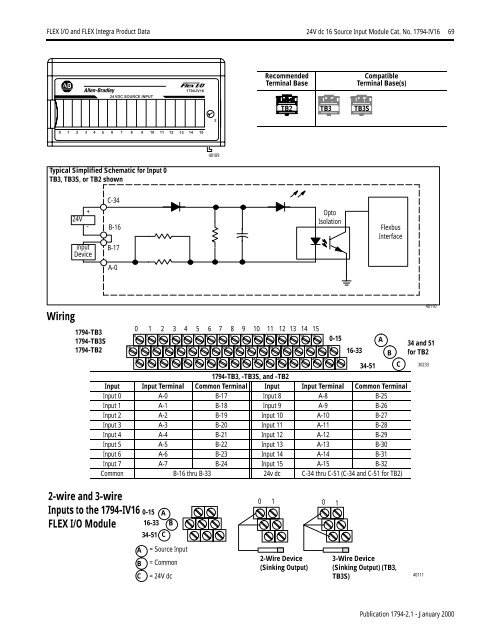
<strong>FLEX</strong> I/O <strong>and</strong> <strong>FLEX</strong> <strong>Integra</strong> Product Data 24V dc 16 Source Input Module Cat. No. 1794-IV16 690 1 2 3 4 5 6 724 VDC SOURCE INPUT1794-IV168 9 10 11 12 13 14 1524010924Vdc16SourceInputModule Cat. No. 1794-IV16RecommendedTerminal BaseTB2 TB3 TB3SCompatibleTerminal Base(s)Typical Simplified Schematic for Input 0TB3, TB3S, or TB2 shownC-3424V + -InputDeviceB-16B-17OptoIsolationFlexbusInterfaceA-0Wiring1794-TB31794-TB3S1794-TB20 1 2 3 4 5 6 7 8 9 10 11 12 13 14 150 1 2 3 4 5 6 7 8 9 10 11 12 13 14 1516 17 18 19 20 21 22 23 24 25 26 27 28 29 30 31 32 3334 35 36 37 38 39 40 41 42 43 44 45 46 47 48 49 50 511794-TB3, -TB3S, <strong>and</strong> -TB2Input Input Terminal Common Terminal Input Input Terminal Common TerminalInput 0 A-0 B-17 Input 8 A-8 B-25Input 1 A-1 B-18 Input 9 A-9 B-26Input 2 A-2 B-19 Input 10 A-10 B-27Input 3 A-3 B-20 Input 11 A-11 B-28Input 4 A-4 B-21 Input 12 A-12 B-29Input 5 A-5 B-22 Input 13 A-13 B-30Input 6 A-6 B-23 Input 14 A-14 B-31Input 7 A-7 B-24 Input 15 A-15 B-32Common B-16 thru B-33 24v dc C-34 thru C-51 (C-34 <strong>and</strong> C-51 for TB2)0-1516-3334-51ABC 302334011034 <strong>and</strong> 51for TB22-wire <strong>and</strong> 3-wireInputs to the 1794-IV16<strong>FLEX</strong> I/O Module0-15 A16-33 B34-51 C0 1 0 1ABC= Source Input= Common= 24V dc2-Wire Device(Sinking Output)3-Wire Device(Sinking Output) (TB3,TB3S)40111Publication 1794-2.1 - January 2000